England Approved Document K
Approved Document K: protection from falling, collision and impact
Library captured 10 September 2026 · Source updated 3 January 2013
The Building Regulations 2010
#Source page 1
Protection from falling, collision and impact
APPROVED DOCUMENT
K1Stairs, ladders and ramps
K2Protection from falling
K3Vehicle barriers and loading bays
K4Protection against impact with glazing
K5Additional provisions for glazing in buildings other than dwellings
K6Protection against impact from and trapping by doors
2013 edition – for use in England*
Main changes in the 2013 edition
#Source page 2
This approved document supports Part K: Protection from falling, collision and impact. It takes effect on 6 April 2013 for use in England*. The 1998 edition (incorporating 2000 and 2010 amendments) will continue to apply to work started before 6 April 2013, or to work subject to a building notice, full plans application or initial notice submitted before 6 April 2013.
The main changes in this approved document are that:
•The document has been updated to amalgamate Approved Document N: Glazing – safety in relation to impact, opening and cleaning, along with some overlapping guidance that resided in Approved Document M: Access to and use of buildings.
•References have been updated to standards as a requisite of the harmonised standard in relation to ‘safe breaking’ and the testing methods.
•References have been updated to standards as a requisite of the harmonised standard and the National Annex in relation to the resistance of loads for barriers.
•Tables and diagrams have been amended and simplified.
•A new-style format is used, but there are no new technical requirements.
•Key terms have been updated and an index has been introduced.
* This approved document gives guidance for compliance with the Building Regulations for building work carried out in England. It also applies to building work carried out on excepted energy buildings in Wales as defined in the Welsh Ministers (Transfer of Functions) (No. 2) Order 2009.
The approved documents
#Source page 3
What is an approved document?
The Secretary of State has approved a series of documents that give practical guidance about how to meet the requirements of the Building Regulations 2010 for England. Approved documents give guidance on each of the technical parts of the regulations and on regulation 7 (see the back of this document).
Approved documents set out what, in ordinary circumstances, may be accepted as reasonable provision for compliance with the relevant requirements of the Building Regulations to which they refer. If you follow the guidance in an approved document, there will be a presumption of compliance with the requirements covered by the guidance. However, compliance is not guaranteed; for example, ‘normal’ guidance may not apply if the particular case is unusual in some way.
Note that there may be other ways to comply with the requirements – there is no obligation to adopt any particular solution contained in an approved document. If you prefer to meet a relevant requirement in some other way than described in an approved document, you should discuss this with the relevant building control body.
In addition to guidance, some approved documents include provisions that must be followed exactly, as required by regulations or where methods of test or calculation have been prescribed by the Secretary of State.
This approved document relates only to the particular requirements of the Building Regulations that the document addresses. However, building work must also comply with any other applicable requirements of the Building Regulations.
How to use this approved document
Each document uses the following conventions.
a.Text against a green background is an extract from the Building Regulations 2010 or the Building (Approved Inspectors etc.) Regulations 2010 (both as amended). These extracts set out the legal requirements of the regulations.
b.Key terms, printed in green, are defined in Appendix A.
c.When this approved document refers to a named standard or other document, the relevant version is listed in Appendix B (standards). However, if the issuing body has revised or updated the listed version of the standard or document, you may use the new version as guidance if it continues to address the relevant requirements of the Building Regulations.
Where you can get further help
#Source page 4
If you do not understand the technical guidance or other information in this approved document or the additional detailed technical references to which it directs you, you can seek further help through a number of routes, some of which are listed below.
a.The Planning Portal website: www.planningportal.gov.uk.
b.If you are the person undertaking the building work: either from your local authority building control service or from an approved inspector.
c.If you are registered with a competent person scheme: from the scheme operator.
d.If your query is highly technical: from a specialist or an industry technical body for the relevant subject.
The Building Regulations
#Source page 5
The following is a high level summary of the Building Regulations relevant to most types of building work. Where there is any doubt you should consult the full text of the regulations, available at www.legislation.gov.uk.
Building work
Regulation 3 of the Building Regulations defines ‘building work’. Building work includes:
a.the erection or extension of a building
b.the provision or extension of a controlled service or fitting
c.the material alteration of a building or a controlled service or fitting.
Regulation 4 states that building work should be carried out in such a way that, when work is complete:
a.for new buildings or work on a building that complied with the applicable requirements of the Building Regulations: the building complies with the applicable requirements of the Building Regulations
b.for work on an existing building that did not comply with the applicable requirements of the Building Regulations:
(i)the work itself must comply with the applicable requirements of the Building Regulations
(ii)the building must be no more unsatisfactory in relation to the requirements than before the work was carried out.
Material change of use
Regulation 5 defines a ‘material change of use’ in which a building or part of a building that was previously used for one purpose will be used for another.
The Building Regulations set out requirements that must be met before a building can be used for a new purpose. To meet the requirements, the building may need to be upgraded in some way.
Materials and workmanship
In accordance with regulation 7, building work must be carried out in a workmanlike manner using adequate and proper materials. Guidance on materials and workmanship is given in Approved Document 7.
Energy efficiency requirements
Part 6 of the Building Regulations imposes additional specific requirements for energy efficiency.
If a building is extended or renovated, the energy efficiency of the existing building or part of it may need to be upgraded.
Notification of work
#Source page 6
Most building work and material changes of use must be notified to a building control body unless one of the following applies.
a.It is work that will be self-certified by a registered competent person or certified by a registered third party.
b.It is work exempted from the need to notify by regulation 12(6A) of, or Schedule 4 to, the Building Regulations.
Responsibility for compliance
People who are responsible for building work (e.g. agent, designer, builder or installer) must ensure that the work complies with all applicable requirements of the Building Regulations. The building owner may also be responsible for ensuring that work complies with the Building Regulations. If building work does not comply with the Building Regulations, the building owner may be served with an enforcement notice.
Contents
#Source page 7
The approved documents
Page i
The Building Regulations
iii
Approved Document K: Protection from falling, collision and impact
1
Requirement K1: Stairs, ladders and ramps
3
Section 1: Stairs and ladders
4
Section 2: Ramps
18
Requirement K2: Protection from falling
#Source page 8
22
Section 3: Protection from falling
23
Requirement K3: Vehicle barriers and loading bays
26
Section 4: Vehicle barriers and loading bays
27
Requirement K4: Protection against impact with glazing
30
Section 5: Protection against impact with glazing
31
Requirement K5.1: Protection from collision with open windows etc.
35
Section 6: Protection from collision with open windows etc.
36
Requirement K5.2: Manifestation of glazing
38
**Section 7: Manifestation of glazing** 39
#Source page 9
Critical locations 39
Permanent methods to indicate glazing, and alternative methods 39
Requirement K5.3: Safe opening and closing of windows etc. 41
Performance 41
Section 8: Safe opening and closing of windows etc. 42
Location of controls 42
Prevention of falls 42
Requirement K5.4: Safe access for cleaning windows etc. 43
Performance 43
Section 9: Safe access for cleaning windows etc. 44
Safe access methods 44
Requirement K6: Protection against impact from and trapping by doors 47
Performance 47
Section 10: Protection against impact from and trapping by doors 48
Safety features 48
Hazards on access routes 49
Appendix A: Key terms 51
Appendix B: Standards referred to 53
Index 54
Page 10
#Source page 10
Approved Document K: Protection from falling, collision and impact
#Source page 11
Summary
0.1This approved document gives guidance on how to comply with Parts K1, K2, K3, K4, K5.1, K5.2, K5.3, K5.4 and K6 of the Building Regulations. It contains the following sections:
Section 1: Guidance on aspects of the geometry of stairs, special stairs, fixed ladders and handrails for and guarding of stairs
Section 2: Guidance on ramps and guarding of ramps
Section 3: Guidance on protection from falling
Section 4: Guidance on vehicle barriers and loading bays
Section 5: Guidance on protection against impact with glazing
Section 6: Guidance on protection from collision with open windows etc.
Section 7: Guidance on manifestation of glazing
Section 8: Guidance on safe opening and closing of windows etc.
Section 9: Guidance on safe access for cleaning windows etc.
Section 10: Guidance on protection against impact from and trapping by doors.
Application
0.2Regulation 3 defines building work such that the following applies.
a.Glazing which is installed in a location where there was none previously as part of the erection, extension or material alteration of a building (other than an exempt building), and the replacement of a whole unit (i.e. the frame and glazing) is building work and is subject to requirement K4 and K5.2.
b.The replacement of glazing whilst retaining an existing frame (e.g. as a repair) is not building work, but the supply of the glazing may be subject to consumer protection legislation.
0.3Requirement K1 applies to means of access outside a building only when the access is part of the building (i.e. attached). For example, requirement K1 does not apply to steps on land leading to a building, but does apply to entrance steps which are part of the building.
0.4Regarding access routes.
a.Where access and circulation routes form part of a means of escape for people in case of fire, refer to Approved Document B: Fire safety, Volume 1 – Dwellinghouses, and Volume 2 – Buildings other than dwellinghouses.
b.For external pedestrian access and circulation routes to buildings, from the boundary of the site and car parking, reference should also be made to Approved Document M: Access to and use of buildings.
Interaction with other legislation
0.6The guidance provided in this document is in relation to the permanent features which form part of the building providing reasonable safety in the appropriate circumstances. However, there may well be particular situations, such as access for maintenance required less frequently than once a month (e.g. see paragraph 1.42b), where such permanent features may be less appropriate. Where
Page 12
#Source page 12
this may be the case the Construction (Design and Management) Regulations 2007 provides detail on procedures for safe use of temporary means of access, together with focus on effective planning and management of risk.
0.7Health and safety regulations such as the Workplace (Health, Safety and Welfare) Regulations 1992 may impose requirements on employers and those in control of premises used as workplaces in relation to certain physical characteristics of the workplace. Where such regulations apply there may be confusion as to whether the Building Regulations or health and safety requirements take precedence, as both will apply. Where an inspector for the purposes of the Health and Safety at Work, etc. Act 1974 has identified a contravention of such health and safety regulations they may seek to serve an improvement notice to secure compliance. In such circumstances the inspector is prevented by virtue of section 23(3) of the Health and Safety at Work, etc. Act 1974 from requiring measures which are more onerous than necessary to comply with any requirements of the Building Regulations, unless the specific requirement of health and safety regulations are themselves more onerous. Where applicable the following cross-referencing should be made.
a.For building work relating to requirement K1 of the Building Regulations, regarding the design of stairs, ladders and ramps, see regulation 17 of the Workplace (Health, Safety and Welfare) Regulations 1992. Regulation 17 relates to permanent stairs, ladders and ramps on pedestrian routes within the workplace premises, including those used to give access for maintenance to parts of the workplace premises.
b.For building work relating to requirement K2 of the Building Regulations, regarding the avoidance of risk from falling when working at height, see regulation 6 of the Work at Height Regulations 2005.
c.For building work relating to requirement K3 of the Building Regulations, regarding the design of vehicle barriers and loading bays, see regulation 17 of the Workplace (Health, Safety and Welfare) Regulations 1992.
d.For building work relating to requirement K4 of the Building Regulations, regarding the prevention of personal injury, see regulation 14(1)(a) of the Workplace (Health, Safety and Welfare) Regulations 1992.
e.For building work relating to requirement K5.1 of the Building Regulations, regarding the requirements for projecting windows, skylights and ventilators, see regulation 15(2) of the Workplace (Health, Safety and Welfare) Regulations 1992.
f.For building work relating to requirement K5.2 of the Building Regulations, regarding the requirements for marking windows, transparent or translucent doors, gates and walls, see regulation 14(1)(b) of the Workplace (Health, Safety and Welfare) Regulations 1992.
g.For building work relating to requirement K5.3 of the Building Regulations, regarding the requirements for opening, closing or adjusting windows, skylights and ventilators, see regulation 15(1) of the Workplace (Health, Safety and Welfare) Regulations 1992.
h.For building work relating to requirement K5.4 of the Building Regulations, regarding the requirements for cleaning windows and skylights, etc., see regulation 16 of the Workplace (Health, Safety and Welfare) Regulations 1992.
i.For building work relating to requirement K6 of the Building Regulations, regarding the requirements for doors and gates, see regulation 18 of the Workplace (Health, Safety and Welfare) Regulations 1992.
Requirement K1: Stairs, ladders and ramps
#Source page 13
This approved document deals with the following requirement from Part K of Schedule 1 to the Building Regulations 2010.
| Requirement | Limits on application |
|---|---|
| Stairs, ladders and ramps | |
| K1. Stairs, ladders and ramps shall be so designed, constructed and installed as to be safe for people moving between different levels in or about the building. | Requirement K1 applies only to stairs, ladders and ramps which form part of the building. |
Performance
In the Secretary of State’s view, you can meet requirement K1 by ensuring that the steepness, rise and going, handrails, headroom, length and width of any stairs, ladders and ramps between levels are appropriate to afford reasonable safety to people gaining access to and moving about buildings.
The standard of provision needed to give an acceptable level of safety for access and use depends on the circumstances.
a.The standard of provision may need to be higher in a public building than in a dwelling, because people may not be familiar with the building and there may be more users.
b.A lower standard of provision may be acceptable where access is required only for maintenance, because greater care can be expected from the people requiring to gain access.
Section 1: Stairs and ladders
#Source page 14
Scope
1.1The guidance provided in this document covers internal and external steps and stairs when they are part of the building. Additional guidance is provided in Approved Document M when external stepped access also forms part of the principal entrances and alternative accessible entrances, and when they form part of the access route to the building from the boundary of the site and car parking. See Approved Document M Section 1 (for buildings other than dwellings) and Section 6 (for dwellings).
Steepness of stairs – rise and going
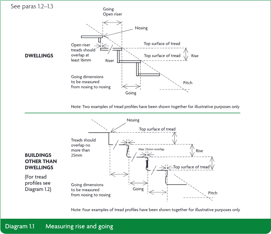
1.2Measure the rise and going as shown in Diagram 1.1. (For steps with tapered treads, see also paragraphs 1.25–1.27.)
Stepped gangways in assembly buildings
#Source page 15
1.3In a flight of steps, for all steps use the measurements for rise and going given for the three stair categories in Table 1.1 below. Use any rise between the minimum and maximum with any going between the minimum and maximum, that complies with the relevant note contained in table 1.1.
| Rise* Minimum (mm) | Rise* Maximum (mm) | Going* Minimum (mm) | Going* Maximum (mm) | |
|---|---|---|---|---|
| Private stair1,2 | 150 | 220 | 220 | 300 |
| Utility stair | 150 | 190 | 250 | 400 |
| General access stair3 | 150 | 170 | 250 | 400 |
[1] The maximum pitch for a private stair is 42°.
[2] For dwellings, for external tapered steps and stairs that are part of the building the going of each step should be a minimum of 280mm.
[3] For school buildings, the preferred going is 280mm and rise is 150mm.
* The normal relationship between the dimensions of the rise and going is: twice the rise plus the going (2R + G) equals between 550mm and 700mm.
For existing buildings the dimensional requirements in Table 1.1 should be followed, unless due to dimensional constraint is it not possible. An alternative proposal should be agreed with the relevant building control body and included in an access strategy (refer to Approved Document M).
Stepped gangways in assembly buildings
1.4The guidance provided in this document covers stairs or ramps that form part of the means of access within an assembly building such as a sports stadium, theatre or cinema. However, if steps are part of the gangways to areas for spectators, the gangways may need to be at different pitches to maintain sightlines for spectators – this may affect the main stairs. Apply all of the following guidance.
a.Ensure that the maximum pitch for gangways to seating areas for spectators is 35°.
b.Align the ends of all rows of seats/wheelchair spaces so that the width of the gangway remains the same.
c.Provide transverse gangways to give access from the side to storey exits (vomitory exits) within the body of a seating layout.
d.Ensure that transverse gangways and radial gangways in auditoria with tiered seating do not cross. Offset the connections between transverse gangways and radial gangways so that the flow of people to the exits is smooth.
e.In stepped tiers, use the following measurements for each step in the gangway:
(i)minimum height: 100mm
(ii)maximum height: 190mm
If there are two or more rises to each row of seats, make each step an equal height.
f.In a tier that is uninterrupted by cross-gangways, and where the pitch exceeds 25°, use a maximum number of steps of 40.
Construction of steps
#Source page 16
g.Where an exit is approached from a stepped gangway, place a landing the width of the exit and a minimum of 1100mm deep immediately in front of the exit doors.
h.For stepped side gangways, provide a handrail in accordance with paragraphs 1.34 and 1.36.
i.In stepped tiers, maintain the same level between the seatway and the nearest step.
j.Gangways should not be less than 1100mm wide unless used by not more than 50 persons, in which case gangways should be a minimum of 900mm.
Construction of steps
For all buildings
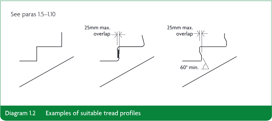
1.5Have level treads on steps, ensuring that the rise and going of each step are consistent throughout a flight of steps and are in accordance with Table 1.1.
For buildings other than dwellings
1.6Use risers that are not open.
a.It removes the possibility of the front of a foot or a walking aid being caught underneath a tread during ascent, possibly causing a fall.
b.It avoids the feeling of insecurity people get when looking through open risers on a stair.
1.7For steps, apply both of the following guidance.
a.Make step nosings apparent: use a material that will contrast visually, a minimum of 55mm wide, on both the tread and the riser.
b.Avoid, if possible, step nosings that protrude over the tread below. If the nosing protrudes, ensure that this is by no more than 25mm (see Diagram 1.2).
1.8If the soffit beneath a stair is less than 2m above floor level, protect the area beneath a stair with one of the following.
a.Guarding and low level cane detection.
b.A barrier giving the same degree of protection.
For dwellings
1.9Steps may have open risers if they comply with both of the following guidance.
a.Overlap treads by a minimum of 16mm.
b.Construct the steps so that a 100mm diameter sphere cannot pass through the open risers.
For common access areas in buildings that contain flats
1.10Provide a stair with steps that comply with all of the following guidance.
a.Make step nosings apparent: use a material that will contrast visually, 50mm to 65mm wide on the tread and 30mm to 55mm on the riser.
b.Use a suitable tread nosing profile, as shown in Diagram 1.2.
c.Use risers which are not open.
Headroom for stairs
#Source page 17
Headroom for stairs
For all buildings
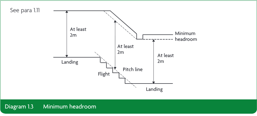
1.11On the access between levels, provide the minimum headroom shown in Diagram 1.3.
For buildings other than dwellings and for common access areas in buildings that contain flats
1.12Provide all means of escape routes with a minimum clear headroom of 2m, except in doorways.
For loft conversions in dwellings
#Source page 18
For loft conversions in dwellings
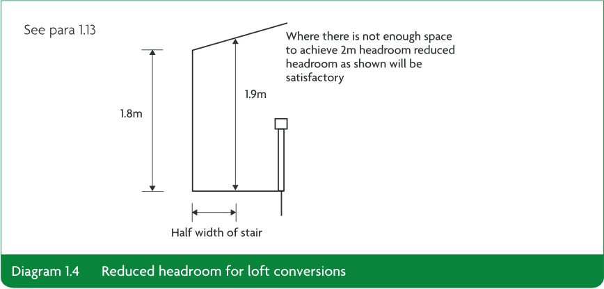
1.13Where there is not enough space to achieve the height shown in Diagram 1.3, provide the reduced headroom shown in Diagram 1.4.
Width of flights of stairs
For buildings other than dwellings
1.14For stairs that form part of means of escape, refer also to Approved Document B: Fire safety, Volume 2 – Buildings other than dwellinghouses.
1.15For flights of stairs, provide all of the following.
a.A minimum stair width between enclosing walls, strings or upstands of 1200mm.
b.A minimum width between handrails of 1000mm.
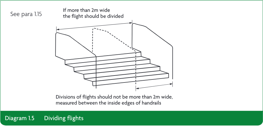
c.If the flight is more than 2m wide, divide it into flights a minimum of 1000mm wide, as shown in Diagram 1.5
d.For access for maintenance, see paragraph 1.42.
For dwellings
1.16In exceptional circumstances where severely sloping plots are involved, a stepped change of level within the entrance storey may be unavoidable. In those instances ensure that stairs within the entrance storey of a dwelling have flights with a minimum stair width of 900mm.
Length of flights of stairs
#Source page 19
Length of flights of stairs
For all buildings
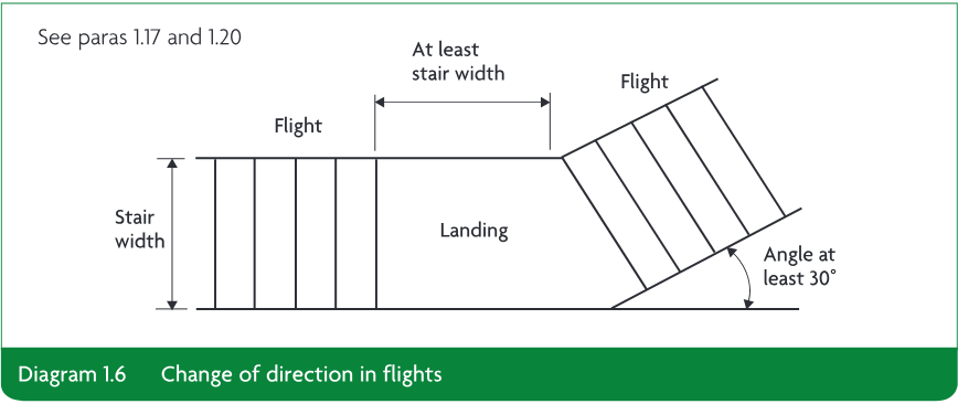
1.17If stairs have more than 36 risers in consecutive flights, make a minimum of one change of direction between flights, as shown in Diagram 1.6.
For buildings other than dwellings and common access areas in buildings that contain flats
#Source page 20
1.18Comply with all of the following.
a.Do not have single steps.
b.For flights between landings the maximum number of risers should be:
(i)utility stairs – 16 risers
(ii)general access stairs – 12 risers, but exceptionally no more than 16 in small premises where the plan area is restricted
(iii)stairs for access for maintenance, see paragraph 1.42.
Landings for stairs
For all buildings
1.19For means of escape requirements, refer also to Approved Document B: Volume 1 – Dwellinghouses, and Volume 2 – Buildings other than dwellinghouses.
1.20At the top and bottom of every flight, provide landings the width and length at least as great as the smallest width of the flight (see Diagram 1.6).
1.21A landing:
a.may include part of the floor of the building
b.should be kept clear of permanent obstructions
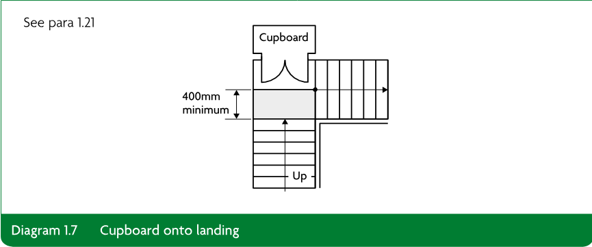
c.may have doors to cupboards and ducts that open over a landing at the top of a flight, as shown in Diagram 1.7, but only when they are kept shut or locked shut when under normal use.
1.22Landings should be level, with the following exception. A landing at the top or bottom of a flight that is formed by the ground may have a gradient, provided that:
a.the maximum gradient along the direction of travel is 1:60
b.the surface is paved ground or otherwise made permanently firm.
For buildings other than dwellings
#Source page 21
1.23Provide all of the following.
a.An unobstructed length a minimum of 1200mm on each landing.
b.Doors that do not swing across landings, except where they comply with paragraph 1.21c.
c.For access for maintenance, see paragraph 1.42.
For dwellings
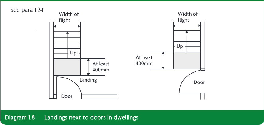
1.24A door may swing across a landing at the bottom of a flight, but only as shown in Diagram 1.8.
Special stairs
Tapered treads
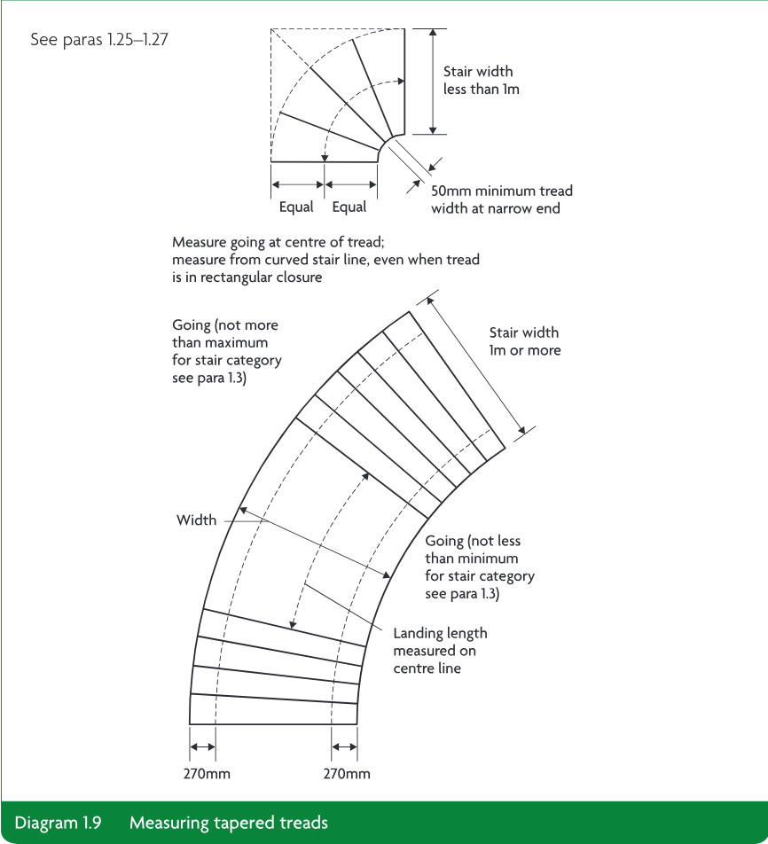
1.25For the rise and going, comply with paragraphs 1.2 and 1.3. For the going of tapered treads, use the measurements shown in Diagram 1.9.
1.26For consecutive tapered treads, use the same going.
1.27If a stair consists of straight and tapered treads, ensure that the going of the tapered treads is not less than the going of the straight treads.
Spiral and helical stairs
#Source page 22
Spiral and helical stairs
1.28Design spiral stairs and helical stairs in accordance with BS 5395-2.
Alternating tread stairs in dwellings
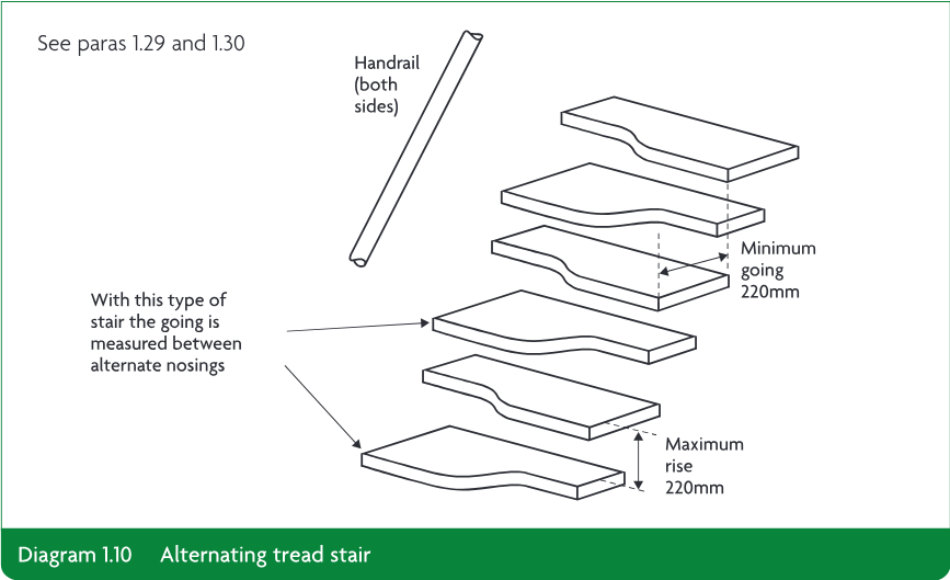
1.29You may use alternating tread stairs – in one or more straight flights – only in a loft conversion, and only when there is not enough space for a stair that satisfies paragraphs 1.2–1.24, and the stair is for access to only one habitable room and, if desired, a bathroom and/or a WC (although this must not be the only WC in the dwelling).
Fixed ladders
#Source page 23
1.30The construction of an alternating tread stair should comply with all of the following.
a.Comply with Diagram 1.10.
b.Make alternating steps uniform with parallel nosings.
c.Have slip-resistant surfaces on treads.
d.Ensure that the tread sizes over the wider part of the step are in line with the dimensions in Table 1.1.
e.Comply with paragraph 1.9b.
f.Provide a minimum clear headroom of 2m.
Fixed ladders
In dwellings
1.31Do not use retractable ladders as means of escape. Refer to Approved Document B: Volume 1 – Dwellinghouses, and Volume 2 – Buildings other than dwellinghouses.
1.32You may use a fixed ladder – with fixed handrails on both sides – only for access in a loft conversion that contains one habitable room, and only when there is not enough space without alteration to the existing space for a stair that satisfies the guidance for dwellings in paragraphs 1.2–1.24.
For industrial buildings
1.33Design and construct stairs, ladders and walkways, as appropriate, in accordance with BS 5395-3 or BS 4211.
Handrails for stairs
#Source page 24
For all buildings
1.34Provide handrails in accordance with all of the following.
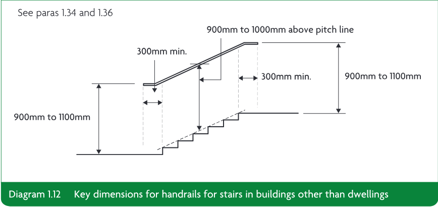
a.Position the top of the handrail 900mm to 1000mm from the pitch line or floor.
b.The handrail may form the top of a guarding if you can match the heights.
c.If the stairs are 1000mm or wider: provide a handrail on both sides.
For buildings other than dwellings and for common access areas in buildings that contain flats and do not have passenger lifts
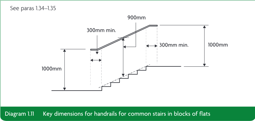
1.35Provide suitable continuous handrails, as dimensioned in Diagram 1.11 (for blocks of flats) and Diagram 1.12 (for buildings other than dwellings), in accordance with both of the following.
a.On each side of the flights.
b.On each side of the landings.
For buildings other than dwellings
1.36Provide handrails in accordance with all of the following (in addition to paragraph 1.34).
a.Where there is full-height structural guarding, if you provide a second (lower) handrail, the vertical height from the pitch line of the steps (or the surface of the ramp) to the top of the second (lower) handrail should be 600mm.
b.Use a continuous handrail along the flights and landings of a ramped or stepped flight.
c.Ensure that handrails do not project into an access route.
d.Ensure that the handrail will contrast visually with the background against which it is seen, without being highly reflective.
In dwellings
#Source page 25
e.Use a surface for the handrail that is slip-resistant and which, in locations subject to extremely cold or hot temperatures, does not become excessively cold or hot to touch. In areas where resistance to vandalism or low maintenance are key factors, use of metals with relatively low thermal conductivity may be appropriate.
f.Finish the end of the handrail in a way that reduces the risk of clothing being caught.
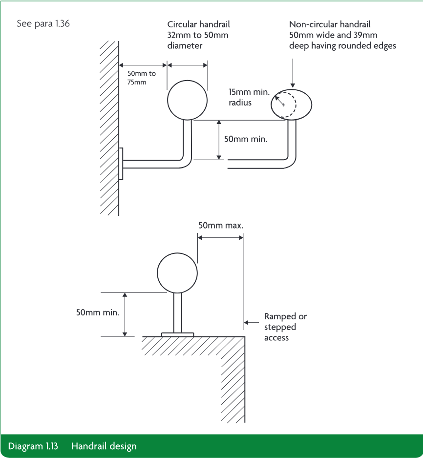
g.Use the handrail profile shown in Diagram 1.13.
In dwellings
1.37In exceptional circumstances where severely sloping plots are involved, a stepped change of level within the entrance storey may be unavoidable. In those instances, if a flight comprises three or more risers, provide a suitable continuous handrail in accordance with both of the following.
a.On each side of the flight.
b.On each side of any intermediate landings.
Guarding of stairs
#Source page 26
Guarding of stairs
For all buildings
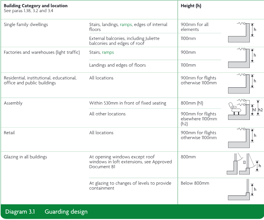
1.38Design the guarding to be the height shown in Diagram 3.1.
1.39In a building that may be used by children under five years of age, construct the guarding to a flight of stairs to do both of the following.
a.Prevent children being held fast by the guarding: ensure that a 100mm sphere cannot pass through any openings in the guarding.
b.Prevent children from readily being able to climb the guarding.
For buildings other than dwellings and for common access areas for buildings that contain flats
#Source page 27
1.40Provide guarding at the sides of flights and landings when there are two or more risers.
In dwellings
1.41Provide guarding at the sides of flights and landings when there is a drop of more than 600mm.
Access for maintenance
For buildings other than dwellings
1.42Where the stairs or ladders will be used to access areas for maintenance they should comply with one of the following.
a.If access will be required a minimum of once per month: follow provisions such as those for private stairs in dwellings or for industrial stairs and ladders in BS 5395-3.
b.If access will be required less frequently than once a month: it may be appropriate, for example, to use portable ladders. The Construction (Design and Management) Regulations 2007 give provisions for safe use of temporary means of access.
Section 2: Ramps
#Source page 28
Scope
2.1The guidance provided in this document covers internal and external ramps when they are part of the building. Additional guidance is provided in Approved Document M when external ramped access also forms part of the principal entrances and alternative accessible entrances, and when they form part of the access route to the building from the boundary of the site and car parking. See Approved Document M Section 1 (for buildings other than dwellings) and Section 6 (for dwellings).
Appearance of ramps
For buildings other than dwellings
2.2Ensure that ramps are readily apparent or clearly signposted.
Steepness of ramps
For all buildings
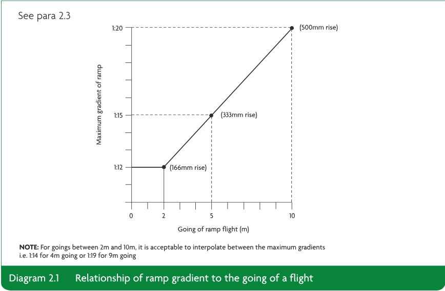
2.3Ensure that the relationship between the gradient of a ramp and its going between landings is as shown in Diagram 2.1.
Construction of ramps
#Source page 29
For buildings other than dwellings
2.4A ramps surface should be selected in accordance with both of the following.
a.Use a ramp surface that is slip resistant, especially when wet, and a colour that will contrast visually with that of the landings.
b.Ensure that the frictional characteristics of the ramp and landing surfaces are similar.
2.5On the open side of any ramp or landing, in addition to any guarding, provide a kerb that complies with both of the following.
a.Is a minimum of 100mm high.
b.Will contrast visually with the ramp or landing.
2.6Where the change of level is:
a.300mm or more: in addition to the ramp, provide two or more clearly signposted steps
b.less than 300mm: provide a ramp instead of a single step.
2.7If the soffit beneath any ramp is less than 2m above floor level, protect the area beneath the ramp with one of the following.
a.Guarding and low level cane detection.
b.A barrier giving the same degree of protection.
Design of ramps
For all buildings
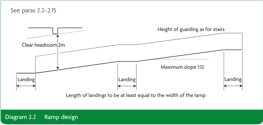
2.8Design all ramps and landings in accordance with Diagram 2.2.
Width of ramps
#Source page 30
For buildings other than dwellings
2.9Regarding the width of a ramp.
a.For a ramp that provides access for people: ensure the ramp has a minimum width between walls, upstands or kerbs of 1500mm.
b.For a ramp that forms a means of escape, refer also to Approved Document B: Volume 2 – Buildings other than dwellinghouses, B1, Section 5.
Obstruction of ramps
For all buildings
2.10Keep ramps clear of permanent obstructions.
Handrails for ramps
For buildings other than dwellings
2.11Provide a handrail on both sides of the ramp and design them to comply with paragraph 1.36.
In dwellings and for common access areas in buildings that contain flats
2.12Provide all of the following.
a.For ramps that are less than 1000mm wide: provide a handrail on one or both sides.
b.For ramps that are 1000mm or more wide: provide a handrail on both sides.
c.For ramps that are 600mm or less in height: you do not need to provide handrails.
d.Position the top of the handrails at a height of 900mm to 1000mm above the surface of the ramp.
e.Choose handrails that give firm support and allow a firm grip.
f.The handrails may form the top of the guarding if you can match the heights.
Landings for ramps
For buildings other than dwellings
2.13Provide all of the following.
a.At the foot and head of a ramp, provide landings which are a minimum of 1200mm long and are clear of any door swings or other obstructions.
b.Ensure that any intermediate landings are a minimum of 1500mm long and are clear of any door swings or other obstructions.
c.If either a wheelchair user cannot see from one end of the ramp to the other or the ramp has three flights or more then provide intermediate landings a minimum of 1800mm wide and a minimum of 1800mm long as passing places.
d.Make all landings level or with a maximum gradient of 1:60 along their length.
For dwellings and for common access areas in buildings that contain flats
#Source page 31
2.14Provide landings for ramps, as described for stairs in paragraphs 1.19–1.22 and 1.24.
Guarding of ramps
For all buildings
2.15Provide guarding for ramps and their landings at their sides in the same way as stairs (see paragraphs 1.38–1.41).
Requirement K2: Protection from falling
#Source page 32
This approved document deals with the following requirement from Part K of Schedule 1 to the Building Regulations 2010.
| Requirement | Limits on application |
|---|---|
| Protection from falling K2.—(a) Any stairs, ramps, floors and balconies and any roof to which people have access, and (b) any light well, basement area or similar sunken area connected to a building, shall be provided with barriers where it is necessary to protect people in or about the building from falling. | Requirement K2 (a) applies only to stairs and ramps which form part of the building. |
Performance
In the Secretary of State’s view, you can meet requirement K2 if, in order to reduce the risk to the safety of people in and around buildings, you use suitable guarding for the appropriate circumstance. Unless otherwise set out elsewhere in this document for particular situations, you can achieve this by the following:
a.in dwellings: provide pedestrian guarding that is capable of preventing people from being injured by falling from a height of more than 600mm
b.in buildings other than dwellings: provide pedestrian guarding that is capable of preventing people from falling more than the height of two risers (or 380mm, if not part of a stair).
The standard of provision for guarding needed to give an acceptable level of safety depends on the circumstances. For example, in a public building the standard of provision may need to be higher than in a dwelling, because people may be less familiar with the building and there may be more users.
For areas where access is required only for maintenance, greater care can be expected from people and therefore a lower standard of provision may be acceptable.
Section 3: Protection from falling
#Source page 33
Siting of pedestrian guarding
For all buildings
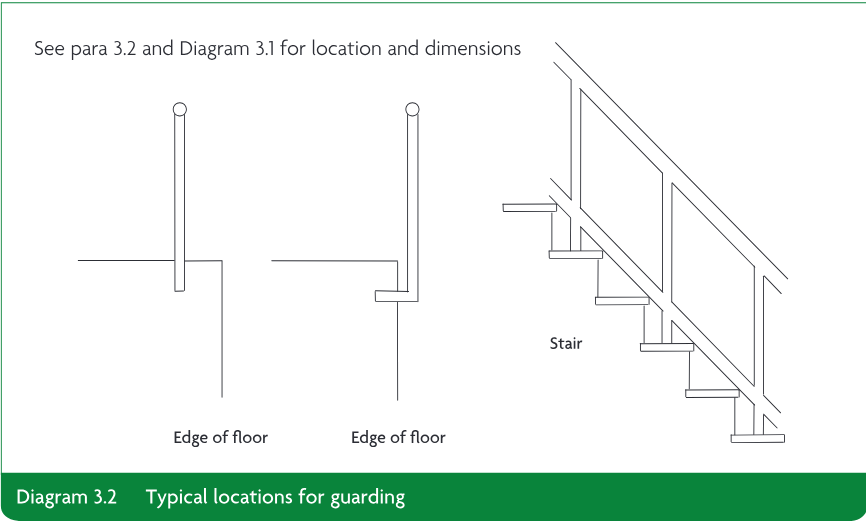
3.1Provide guarding in all of the following locations:
a.where it is reasonably necessary for safety to guard the edges of any part of a floor (including the edge below an opening window), gallery, balcony, roof (including roof lights and other openings), any other place to which people have access, and any light well, basement or similar sunken area next to a building
b.in vehicle parks.
a.on ramps used only for vehicle access
b.in places such as loading bays where it would obstruct normal use.
Design of guarding
For all buildings
3.2Guarding should be provided in accordance with all of the following.
a.Ensure that guarding is, as a minimum, the height shown in Diagram 3.1.
b.You can use any wall, parapet, balustrade or similar obstruction as guarding.
c.Ensure that guarding can resist, as a minimum, the loads given in BS EN 1991-1-1 with its UK National Annex and PD 6688-1-1.
d.Where glazing is used in the guarding, refer also to Section 5 in this approved document.
Page 34
#Source page 34
| Building Category and location | Height (h) | |
|---|---|---|
| Single family dwellings | Stairs, landings, ramps, edges of internal floors | 900mm for all elements |
| External balconies, including Juliette balconies and edges of roof | 1100mm | |
| Factories and warehouses (light traffic) | Stairs, ramps | 900mm |
| Landings and edges of floors | 1100mm | |
| Residential, institutional, educational, office and public buildings | All locations | 900mm for flights otherwise 1100mm |
| Assembly | Within 530mm in front of fixed seating | 800mm (h1) |
| All other locations | 900mm for flights elsewhere 1100mm (h2) | |
| Retail | All locations | 900mm for flights otherwise 1100mm |
| Glazing in all buildings | At opening windows except roof windows in loft extensions, see Approved Document B1 | 800mm |
| At glazing to changes of levels to provide containment | Below 800mm |
See paras 1.38, 3.2 and 3.4
3.3In a building that may be used by children under five years of age during normal use, guarding should be constructed in accordance with both of the following.
a.To prevent children being held fast by the guarding: ensure that a 100mm sphere cannot pass through any openings in the guarding.
b.To prevent children from readily being able to climb the guarding: avoid horizontal rails.
Guarding of areas used for maintenance
#Source page 35
Guarding of areas used for maintenance
For all buildings
3.4Where people will use the stairs or ladders to access areas for maintenance they should comply with one of the following.
a.If access will be required frequently (e.g. a minimum of once per month): follow provisions such as those suggested for dwellings in this Approved Document (see Diagram 3.1).
b.If access will be required less frequently than once a month: it may be appropriate to use temporary guarding or warning notices. The Construction (Design and Management) Regulations 2007 and the Work at Height Regulations 2005 give provisions for such measures.
3.5Use signs as specified in the Health and Safety (Safety Signs and Signals) Regulations 1996.
Requirement K3: Vehicle barriers and loading bays
#Source page 36
This approved document deals with the following requirement from Part K of Schedule 1 to the Building Regulations 2010.
Performance
In the Secretary of State’s view, you can meet requirement K3 if, in order to reduce the risk to the safety of people from collision with vehicles in and about buildings, you:
a.provide vehicle barriers that are capable of resisting or deflecting the impact of vehicles
b.provide loading bays that have an adequate number of exits or refuges which enable people to avoid being struck or crushed by vehicles.
The standard of provision for guarding needed to give an acceptable level of safety depends on the circumstances. For example, in a public building the standard of provision may need to be higher than in a dwelling, because people may be less familiar with the building and there may be more users.
For areas where access is required only for maintenance, greater care can be expected from people and therefore a lower standard of provision may be acceptable.
Section 4: Vehicle barriers and loading bays
#Source page 37
Vehicle barriers
For all buildings
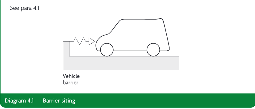
4.1If vehicles have access to a floor, roof or ramp which forms part of a building, provide barriers at any edges which are level with or above the floor or ground or any other route for vehicles (see Diagram 4.1).
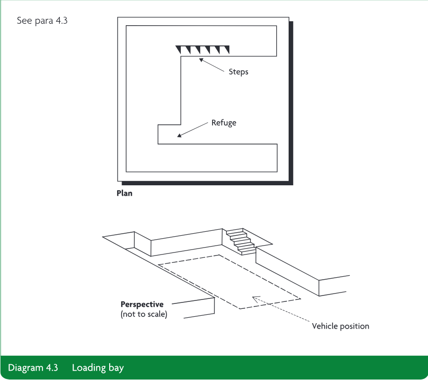
4.2Barriers should be provided in accordance with all of the following.
a.You can use any wall, parapet, balustrade or similar obstacle as a barrier.
b.Construct barriers to be, as a minimum, the height shown in Diagram 4.2.
c.Ensure that barriers can resist the loads given in BS EN 1991-1-1 with its UK National Annex and PD 6688-1-1.
Loading bays
#Source page 38
Loading bays
For all buildings
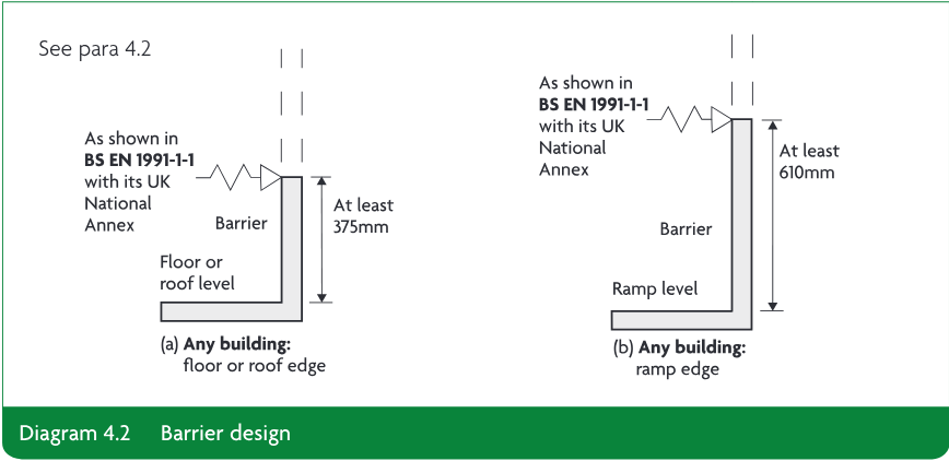
4.3Loading bays should be constructed with exit points in accordance with both of the following.
a.Provide loading bays with a minimum of one exit point from the lower level, as near the centre of the rear wall as possible.
b.For wide loading bays (for three or more vehicles), provide a minimum of two stepped exit points, one on each side, or provide a refuge where people can avoid the path of a vehicle in addition to one stepped exit point (see Diagram 4.3).
Guarding for loading bays
For all buildings
4.4Where there is a danger of people falling, loading bays should be provided with guarding as per the guidance provided in this approved document. If guarding is not practical for the particular circumstances, alternative safeguards should be provided and agreed with the building control body.
Page 39
#Source page 39
Requirement K4: Protection against impact with glazing
#Source page 40
This approved document deals with the following requirement from Part K of Schedule 1 to the Building Regulations 2010.
| Requirement | Limits on application |
|---|---|
| Protection against impact with glazing K4.—Glazing, with which people are likely to come into contact whilst moving in or about the building shall: (a) if broken on impact, break in a way which is unlikely to cause injury; or (b) resist impact without breaking; or (c) be shielded or protected from impact. |
Performance
In the Secretary of State’s view, you can meet requirement K4 if you adopt, in critical locations, one of the following approaches.
a.Measures to limit the risk of cutting and piercing injuries by the use of glazing that is reasonably safe, such that, if breakage did occur, any particles would be relatively harmless.
b.Use of glazing sufficiently robust to ensure that the risk of breakage is low.
c.Steps are taken to limit the risk of contact with the glazing.
Impacts with glazing, particularly glazing in doors and door side panels, and at low level in walls and partitions, can result in cutting and piercing injuries. For doors and door side panels, the risk is greatest for glazing between floor and shoulder level when near to door handles and push plates, especially when normal building movement causes doors to stick.
Hands, wrists and arms are particularly vulnerable. An initial impact at between waist and shoulder levels can be followed by a fall through the glazing, resulting in additional injury to the face and body.
In walls and partitions, away from doors, the risks relate predominantly to glazing at low level. At that level, children are especially vulnerable.
Section 5: Protection against impact with glazing
#Source page 41
Glazing in critical locations
For all buildings
5.1Diagram 5.1 shows critical locations in terms of safety.
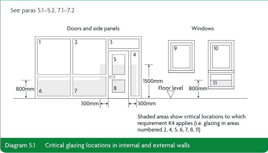
5.2In critical locations, comply with one of the following.
a.Ensure that glazing, if it breaks, will break safely (see paragraphs 5.3 and 5.4).
b.Choose glazing that is one of the following:
(i)robust (see paragraph 5.5)
(ii)in small panes (see paragraphs 5.6 and 5.7).
c.Permanently protect glazing (see paragraph 5.8).
Safe breakage
#Source page 42
5.3Safe breakage is defined in BS EN 12600 section 4 and BS 6206 clause 5.3. In an impact test, a breakage is safe if it creates one of the following.
a.A small clear opening only, with detached particles no larger than the specified maximum size.
b.Disintegration, with small detached particles.
c.Broken glazing in separate pieces that are not sharp or pointed.
5.4A glazing material would be suitable for a critical location if it complies with one of the following.
a.It satisfies the requirements of Class 3 of BS EN 12600 or Class C of BS 6206.
b.It is installed in a door or in a door side panel and has a pane width exceeding 900mm and it satisfies the requirements of Class 2 of BS EN 12600 or Class B of BS 6206.
Robustness
5.5Some glazing materials such as annealed glass gain strength through thickness; others such as polycarbonates or glass blocks are inherently strong.
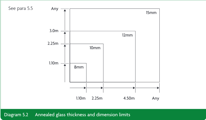
The maximum dimensions for annealed glass of different thicknesses for use in large areas forming fronts to shops, showrooms, offices, factories and public buildings with four edges supported are shown in Diagram 5.2 (see also paragraph 7.1).
Glazing in small panes
#Source page 43
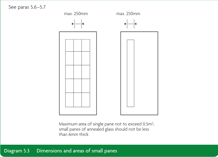
5.6In the context of this approved document, a ‘small pane’ is an isolated pane or one of a number of panes held in glazing bars, traditional leaded lights or copper lights (see Diagram 5.3).
5.7Small panes should be provided in accordance with all of the following.
a.In a small annealed glass pane, use glass with a minimum 6mm nominal thickness except in the situation described in b.
b.In traditional leaded or copper lights, when fire resistance is not important, you may use 4mm glass.
c.Use the dimensions and areas shown in Diagram 5.3.
Permanent screen protection
#Source page 44
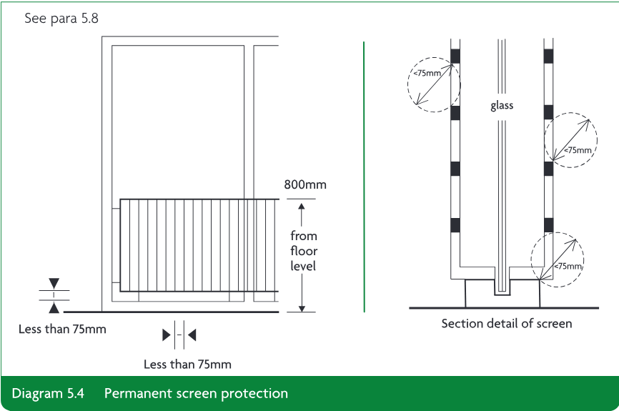
5.8If glazing in a critical location is protected by a permanent screen then the glazing itself does not need to comply with requirement K4.
The permanent screen should comply with all of the following.
a.Prevent a sphere of 75mm from coming into contact with the glazing.
b.Be robust.
c.If it protects glazing installed to help prevent people from falling, be difficult to climb (e.g. no horizontal rails).
See Diagram 5.4.
Requirement K5.1: Protection from collision with open windows etc.
#Source page 45
This approved document deals with the following requirement from Part K of Schedule 1 to the Building Regulations 2010.
| Requirement | Limits on application |
|---|---|
| Protection from collision with open windows etc. K5.1—Provision shall be made to prevent people moving in or about the building from colliding with open windows, skylights or ventilators. | Requirement K5.1 does not apply to dwellings. |
Performance
In the Secretary of State’s view, you can meet requirement K5.1 if windows, skylights and ventilators can be left open without danger of people colliding with them. You can achieve this by one of the following methods.
a.Install windows, skylights and ventilators so that projecting parts cannot come into contact with people moving in and around the building.
b.Install features which guide people moving in or around the building away from any open window, skylight or ventilator.
In special cases, such as in spaces where access is required only for maintenance, greater care can be expected from people and therefore a lower standard of provision may be acceptable.
Section 6: Protection from collision with open windows etc.
#Source page 46
Projecting parts
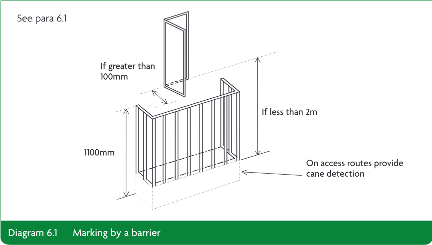
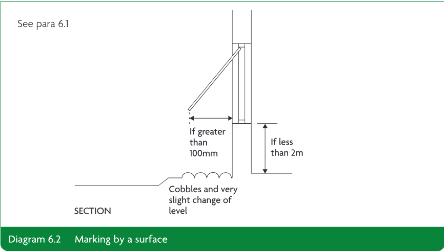
6.1Where parts of windows, skylights and ventilators project inside or outside a building, indicate this as shown in Diagram 6.1 or Diagram 6.2 (but see also paragraph 6.2).
Spaces used only for maintenance
#Source page 47
Spaces used only for maintenance
6.2In spaces which are used infrequently and only for maintenance you can, for example, mark the projecting part clearly to make it easy to see.
Requirement K5.2: Manifestation of glazing
#Source page 48
This approved document deals with the following requirement from Part K of Schedule 1 to the Building Regulations 2010.
| Requirement | Limits on application |
|---|---|
| Manifestation of glazing K5.2—Transparent glazing, with which people are likely to come into contact while moving in or about the building, shall incorporate features which make it apparent. | Requirement K5.2 does not apply to dwellings. |
Performance
In the Secretary of State’s view, you can meet requirement K5.2 by including, in critical locations, permanent means of indicating the presence of large uninterrupted areas of transparent glazing.
Section 7: Manifestation of glazing
#Source page 49
Critical locations
7.1Critical locations (see paragraph 5.1) include large uninterrupted areas of transparent glazing which form, or are part of, the internal or external walls and doors of shops, showrooms, offices, factories, public or other non-domestic buildings.
7.2The risk of collision is greatest when two parts of the building, or the building and its immediate surroundings, are at the same level but separated by transparent glazing and people may think they can walk from one part to the other.
Permanent methods to indicate glazing, and alternative methods
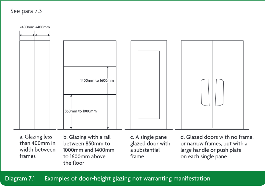
7.3People moving in or around a building might not see glazing in critical locations and can collide with it. To avoid this one of the following should be adopted.
a.Use permanent manifestation to make glazing apparent (see paragraph 7.4).
b.Use alternative indications of glazing, such as mullions, transoms, door framing or large pull or push handles (see Diagram 7.1).
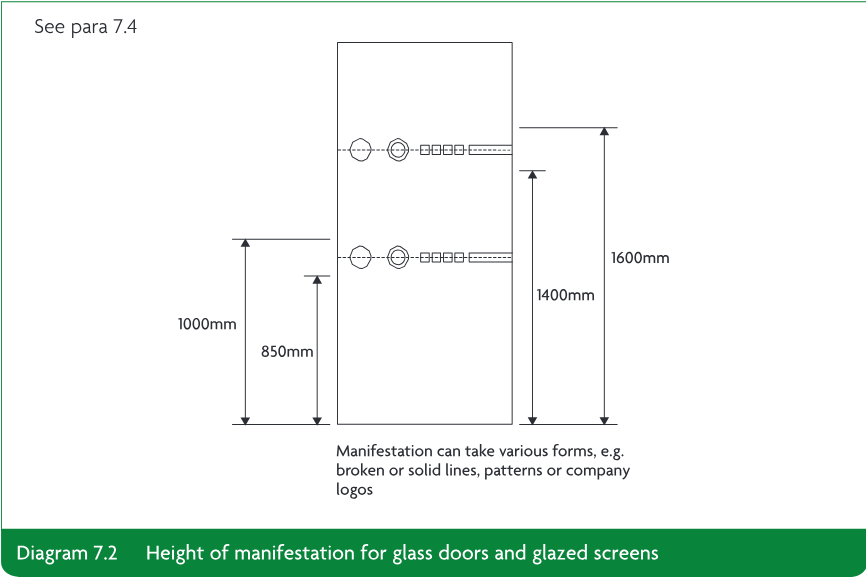
7.4Provide glass doors and glazed screens (including glazed screens alongside a corridor) with all of the following.
a.Manifestation at two levels, as shown in Diagram 7.2.
b.Manifestation that will contrast visually with the background seen through the glass, both from inside and outside, in all lighting conditions.
c.Manifestation in the form of a logo or sign, a minimum of 150mm high (repeated if on a glazed screen), or a decorative feature such as broken lines or continuous bands, a minimum of 50mm high.
d.Where glazed doors are beside or part of a glazed screen, they are clearly marked with a high-contrast strip at the top and on both sides.
e.Where glass doors may be held open, they are protected with guarding to prevent people colliding with the leading edge.
Page 50
#Source page 50
Requirement K5.3: Safe opening and closing of windows etc.
#Source page 51
This approved document deals with the following requirement from Part K of Schedule 1 to the Building Regulations 2010.
| Requirement | Limits on application |
|---|---|
| Safe opening and closing of windows etc. K5.3—Windows, skylights and ventilators which can be opened by people in or about the building shall be so constructed or equipped that they may be opened, closed or adjusted safely. | Requirement K5.3 does not apply to dwellings. |
Performance
In the Secretary of State’s view, you can meet requirement K5.3 by ensuring that people can safely operate windows, skylights and ventilators that open.
Section 8: Safe opening and closing of windows etc.
#Source page 52
Location of controls
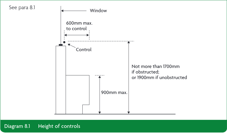
8.1Regarding the controls to operate windows, skylights and ventilators, one of the following should be provided.
a.Controls positioned as shown in Diagram 8.1.
b.If controls cannot be positioned as shown in Diagram 8.1 within safe reach of a permanent stable surface, provide a safe manual or electrical means of remote operation.
Prevention of falls
8.2Where a person may fall through a window above ground floor level, provide suitable opening limiters, to restrain the window sufficiently to prevent such falls, or guarding (see Section 3).
Requirement K5.4: Safe access for cleaning windows etc.
#Source page 53
This approved document deals with the following requirement from Part K of Schedule 1 to the Building Regulations 2010.
| Requirement | Limits on application |
|---|---|
| Safe access for cleaning windows etc. K5.4—Provision shall be made for any windows, skylights, or any transparent or translucent walls, ceilings or roofs to be safely accessible for cleaning. | Requirement K5.4 does not apply to: (a) dwellings, or (b) any transparent or translucent elements whose surfaces are not intended to be cleaned. |
Performance
In the Secretary of State’s view, you can meet requirement K5.4 if, where a person may fall from a window, you provide safe means of access for cleaning both sides of the glass.
Section 9: Safe access for cleaning windows etc.
#Source page 54
Safe access methods
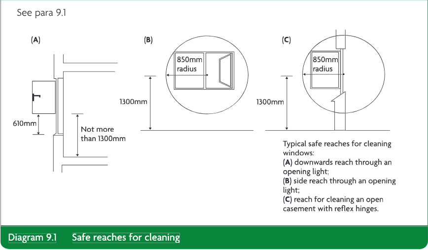
9.1Where a person standing on the ground, a floor or other permanent stable surface cannot safely clean a glazed surface use one of the following methods.
a.Provide windows of a size and design that allows people to clean the outside safely from inside the building (see Diagram 9.1). If windows reverse for cleaning, fit a mechanism to hold the window in the reversed position. For additional guidance, see BS 8213-1.
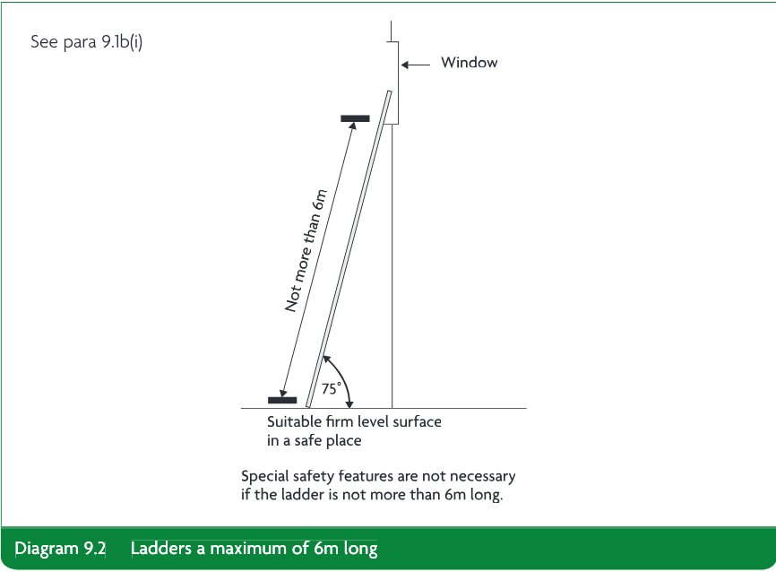
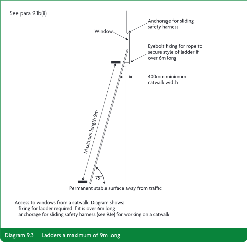
b.Provide access ladders as follows:
(i)for ladders up to 6m long: as shown in Diagram 9.2
(ii)for ladders between 6m and 9m long: with safety features, as shown in Diagram 9.3.
Page 55
#Source page 55
c.Provide access equipment such as suspended cradles or travelling ladders, with attachments for safety harnesses (see Diagram 9.3).
d.Provide suitable anchorage points for safety harnesses (see Diagram 9.3) or abseiling hooks.
e.Provide walkways at least 400mm wide, either with guarding at least 1100mm high, or with anchorages for sliding safety harnesses (see Diagram 9.3).
f.If the methods described in (a) to (e) are not possible, provide space for scaffold towers from which glazed surfaces can be cleaned.
Page 56
#Source page 56
Requirement K6: Protection against impact from and trapping by doors
#Source page 57
This approved document deals with the following requirement from Part K of Schedule 1 to the Building Regulations 2010.
| Requirement | Limits on application |
|---|---|
| Protection against impact from and trapping by doors K6.—(1) Provision shall be made to prevent any door or gate: (a) which slides or opens upwards, from falling onto any person; and (b) which is powered, from trapping any person. (2) Provision shall be made for powered doors and gates to be opened in the event of a power failure. (3) Provision shall be made to ensure a clear view of the space on either side of a swing door or gate. | Requirement K6 does not apply to: (a) dwellings, or (b) any door or gate which is part of a lift. |
Performance
In the Secretary of State’s view, you can meet requirement K6 if you take measures to prevent the opening and closing of doors and gates presenting a safety hazard.
Section 10: Protection against impact from and trapping by doors
#Source page 58
Safety features
10.1Doors and gates should be constructed in accordance with all of the following.
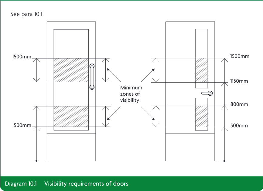
a.In door leaves and side panels wider than 450mm, include vision panels towards the leading edge of the door to provide, as a minimum, the zone or zones of visibility shown in Diagram 10.1.
b.For sliding doors and gates, provide both of the following:
(i)a stop or other effective means to prevent them coming off the end of the track
(ii)a retaining rail to prevent doors and gates falling if the suspension system fails or the rollers leave the track.
c.On upward-opening doors and gates, fit a device to stop them falling in a way that may cause injury.
d.For power-operated doors and gates, provide all of the following:
(i)safety features (such as a pressure-sensitive door edge which operates the power switch) to prevent injury to people who are struck or trapped
(ii)a readily identifiable and accessible stop switch
(iii)the ability for manual or automatic opening if there is a power failure, when necessary for health or safety.
Hazards on access routes
#Source page 59
Hazards on access routes
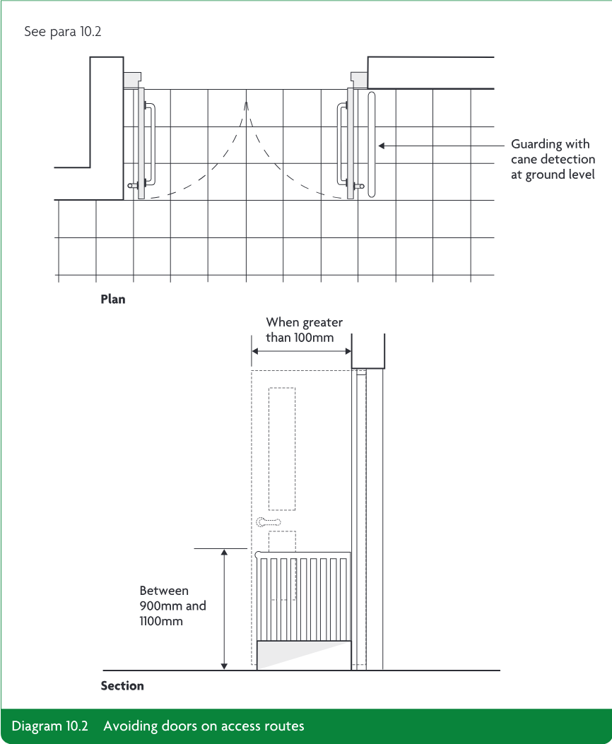
10.2If, during normal use, doors (excluding fire escape doors) swing out by more than 100mm towards an access route, protect them as shown in Diagram 10.2.
Page 60
#Source page 60
Appendix A: Key terms
#Source page 61
The following are key terms used in this document:
Accessible entrance An entrance which is accessible to people regardless of disability, age or gender.
Alternating tread stair A stair with paddle-shaped treads where the wide portion is on alternate sides on consecutive treads (see paragraphs 1.29 and 1.30).
Barrier A structure – either a raised rail or a solid wall – that denies access to another area.
Common stair Serving more than one dwelling.
Contrast visually The perception of a visual difference between two elements of the building, or fittings within the building, so that the difference in light reflectance value is of sufficient points to distinguish between the two elements.
Flight A continuous series of steps or a continuous slope (ramp) between landings. (For the widths and lengths of flights see paragraphs 1.14–1.24.)
General access stair A stair intended for all users of a building on a day-to-day basis, as a normal route between levels.
Going For stairs: the depth from front to back of a tread, less any overlap with the next tread above (see paragraphs 1.2 and 1.3). (For the measurement of the going on tapered treads see paragraphs 1.25–1.27.) For ramps: the length of the ramp between landings.
Guarding A barrier that denies pedestrians or vehicles access to another area, for example the floor below (see Diagrams 3.1 and 3.2).
Handrail A rail, at hand height or a little higher, for people to hold for support. (For handrails for stairs, see paragraphs 1.34–1.37; for handrails for ramps, see paragraphs 2.11–2.12.)
Helical stair A stair in a helix around a central void (see paragraph 1.28).
Ladder A means of access to another level, formed by a series of rungs or narrow treads. People normally ascend or descend facing the ladder. (See paragraphs 1.31–1.33.)
Light reflectance value (LRV) The total quantity of visible light reflected by a surface at all wavelengths and directions when illuminated by a light source.
Nosing The leading edge of a stair tread.
Pitch The angle of inclination (slope) between the horizontal and a line connecting the nosings of a stair.
Private stair A stair intended to be used for only one dwelling.
Principal entrance An entrance which a visitor not familiar with the building would normally expect to approach.
Radial gangway A gangway at an angle to the rows of seats/wheelchair spaces or a stepped gangway in tiered seating.
Page 62
#Source page 62
Ramp A slope steeper than 1:20, on which a pedestrian or wheelchair user can move from one level to another (see Section 2).
Rise The height between consecutive treads (see paragraphs 1.2 and 1.3). For ramps: the vertical distance between each end of the ramp flight.
Spiral stair A stair in a helix around a central column (see paragraph 1.28).
Stair width The clear width between the walls or balustrades.
Tapered tread A step in which the going reduces from one side to the other (see paragraphs 1.25–1.27).
Transverse gangway A flat gangway parallel to the rows of seating/wheelchair spaces.
Utility stair A stair used for escape, access for maintenance, or purposes other than as the usual route for moving between levels on a day-to-day basis.
Vomitory exits Storey exits provided within the body of a seating layout.
Appendix B: Standards referred to
#Source page 63
BS EN 1991-1-1 Eurocode 1. Actions on structures. General actions. Densities, self-weight, imposed loads for buildings [2002]
National Annex to BS EN 1991-1-1 UK National Annex to Eurocode 1. Actions on structures. General actions. Densities, self-weight, imposed loads for buildings [2002]
BS 4211 Specification for permanently fixed ladders [2005 + AMD A1, Corrigenda C1, C2]
BS 5395-2 Code of practice for the design of helical and spiral stairs [1984 + AMD 6076, Corrigenda July 2008, C2, C3]
BS 5395-3 Code of practice for the design of industrial type stairs, permanent ladders and walkways [1985 + AMD 14247]
BS 6180 Barriers in and about buildings. Code of practice [2011]
BS 6206 Specification for impact performance requirements for flat safety glass and safety plastics for use in buildings [1981 + AMDs 4580, 5189, 7589, 8156, 8693]
PD 6688-1-1 Recommendations for the design of structures to BS EN 1991-1-1 [2011]
BS 8213-1 Windows doors and rooflights. Design for safety in use and during cleaning of windows, including door-height windows and roof windows. Code of practice [2004]
BS EN 12600 Glass in building – Pendulum test – Impact test method and classification for flat glass [2002 + incorporating corrigendum April 2010]
Index
#Source page 64
A
Access routes 0.4, 1.1, 1.36, 2.1, 10.2; Diagrams 6.1 & 10.2
Alternating tread stairs Diagram 1.10; 1.29–1.30
Approved Document B 0.4, 1.14, 1.19, 1.31, 2.9; Diagram 3.1
Approved Document M 0.4, 1.1; Table 1.1; 2.1, 8.1
B
Barriers Diagram 6.1 See also Vehicle barriers
British Standards Appendix B BS 4211 1.33 BS 5395-2 1.28 BS 5395-3 1.33, 1.42 BS 6180 3.2 BS 6206 5.3, 5.4 BS 8213-1 9.1 BS EN 1991-1-1 3.2, 4.2; Diagram 4.2 BS EN 12600 5.3, 5.4 PD 6688-1-1 3.2, 4.2
Building work 0.2, 0.7
C
Cleaning, safe access for Page 43, 9.1
Collision, protection from Open windows 6.1–6.2 Glazing Page 38, 7.1–7.4 See also Impact, protection from
Critical locations (glazing) Page 30, 5.1; Diagram 5.1; 5.2, 5.4, 5.8. Page 38, 7.1, 7.3
Cupboards Diagram 1.7; 1.21
D
Doors On gangways 1.4 On landings Diagram 1.8; 1.21, 1.23–1.24, 2.13 Protection from impact and trapping Page 47, 10.1–10.2; Diagrams 10.1–10.2
F
Falling, protection from Page 22, 3.1–3.5; Diagrams 3.1–3.2
G
Gangways 1.4
Gates Page 47, 10.1
General access stairs Table 1.1; 1.18
Glazing 0.2 Cleaning 9.1 Critical locations 5.1; Diagram 5.1; 5.2, 5.4, 5.8, 7.1 Guarding 7.4 Manifestation Page 38, 7.1–7.4; Diagram 7.2 Maximum dimensions Diagram 5.2; 5.5 Protection against impact with Page 30, 5.1–5.8 Robustness 5.5 Safe breakage 5.3 Screen protection 5.8 Small panes 5.6–5.7
Going 1.2–1.3; Table 1.1; Diagram 1.1
Guarding Page 22 Design Diagram 3.1; 3.2–3.3 For doors 10.2 For glass doors and glazed screens 7.4 For loating bays 4.4 For maintenance areas 3.4–3.5 For ramps 2.5, 2.7; Diagram 2.2; 2.12, 2.15 Siting 3.1; Diagram 3.2 For stairs 1.8, 1.34, 1.36, 1.38–1.41 For windows 8.2
H
Handrails For ramps 2.11–2.12 For stairs Diagrams 1.11–1.12; 1.34–1.37 For stepped gangways 1.4
Headroom, for stairs 1.11; Diagram 1.3; 1.30 See also Means of escape routes, Loft conversions
Helical stairs 1.28
I
#Source page 65
Impact, protection from Doors Page 47, 10.1–10.2; Diagrams 10.1–10.2 Glazing Page 30, 5.1–5.8; Diagrams 5.1–5.4 See also Collision, protection from
L
Landings For ramps 2.13–2.14 For stairs 1.19–1.24
Ladders 0.7, Page 3 Fixed 1.31–1.33, 1.42 For cleaning windows, etc. 9.1; Diagrams 9.2–9.3 For maintenance 3.4–3.5
Legislation 0.6–0.7 Construction (Design and Management) Regulations 2007 0.6, 1.42, 3.4 Health and Safety at Work, etc. Act 1974 0.7 Health and Safety (Safety Signs and Signals) Regulations 1996 3.5 Work at Height Regulations 2005 0.7, 3.4 Workplace (Health, Safety and Welfare) Regulations 1992 0.7
Loading bays 3.1, Page 26, 4.1–4.4; Diagram 4.3
Loft conversions Alternating tread stairs 1.29; Diagram 1.10 Fixed ladders 1.32 Headroom 1.13; Diagram 1.4
M
Maintenance areas Access 1.42 Guarding 3.4–3.5; Diagram 3.1 Windows 6.2
Manifestation of glazing Page 38, 7.1–7.4; Diagram 7.2
Means of escape routes 0.4, 1.12, 1.14, 1.19, 1.31, 2.9
P
Pitch Diagram 1.1 Gangways 1.4 Private stairs Table 1.1
Private stairs Table 1.1; Diagram 1.1
R
Ramps 0.7, Page 3, 1.4, 2.1–2.15 Appearance 2.2 Construction 2.4–2.7 Design 2.8; Diagram 2.2 Guarding 2.15 Handrails Diagrams 1.12–1.13; 2.11–2.12 Landings Diagrams 1.6–1.8; 2.13–2.14 Steepness Diagram 2.1; 2.3 Width 2.9
Rise Table 1.1; Diagram 1.1; 1.2–1.3
S
Spiral stairs 1.28
Stairs 0.7, Page 3, 1.1–1.30, 1.34–1.42 Alternating treads Diagram 1.10; 1.29–1.30 Construction Table 1.1; Diagram 1.2; 1.5–1.10 Flight width 1.14–1.16; Diagram 1.5 Flight length 1.17–1.24; Diagram 1.6 Going Table 1.1; Diagram 1.1; 1.2–1.3 Guarding 1.38–1.41; Diagram 3.1 Handrails Diagrams 1.11–1.13; 1.34–1.37 Headroom 1.11; Diagram 1.3 Helical stairs 1.28 Landings 1.17–1.24; Diagrams 1.6–1.8 Rise Table 1.1; Diagram 1.1; 1.2–1.3 Spiral stairs 1.28 Stepped gangways 1.4 Tapered treads Diagram 1.9; 1.25–1.27 See also Guarding, Handrails
Skylights Access for cleaning Page 43, 9.1; Diagrams 9.1–9.3 Collision protection Page 35, 6.1–6.2; Diagrams 6.1–6.2 Safe opening and closing Page 41, 8.1–8.2; Diagram 8.1
Stepped tiers 1.4
Steps Table 1.1; Diagram 1.1; 1.5–1.10
T
Tapered tread stairs Table 1.1, 1.25–1.27
U
Utility stairs Table 1.1; Diagram 1.2; 1.10, 1.18
V
#Source page 66
Vehicle barriers Page 26, 4.1–4.2; Diagram 4.1
Ventilators Collision protection Page 35, 6.1–6.2; Diagrams 6.1–6.2 Safe opening and closing Page 41, 8.1–8.2; Diagram 8.1
W
Windows Collision protection Page 35, 6.1–6.2; Diagrams 6.1–6.2 Limiters 8.2 Safe access for cleaning Page 43, 9.1; Diagrams 9.1–9.3 Safe opening and closing Page 41, 8.1; Diagram 8.1 See also Glazing
List of Approved Documents
#Source page 67
The following documents have been published to give guidance on how to meet the Building Regulations. You can find the date of the edition approved by the Secretary of State at www.gov.uk/dclg.
Approved Document A Structure
Approved Document B: Fire Safety Volume 1: Dwellinghouses
Approved Document B: Fire Safety Volume 2: Buildings other than dwellinghouses
Approved Document C Site preparation and resistance to contaminants and moisture
Approved Document D Toxic substances
Approved Document E Resistance to the passage of sound
Approved Document F Ventilation
Approved Document G Sanitation, hot water safety and water efficiency
Approved Document H Drainage and waste disposal
Approved Document J Combustion appliances and fuel storage systems
Approved Document K Protection from falling, collision and impact
Approved Document L1A Conservation of fuel and power (New dwellings)
Approved Document L1B Conservation of fuel and power (Existing dwellings)
Approved Document L2A Conservation of fuel and power (New buildings other than dwellings)
Approved Document L2B Conservation of fuel and power (Existing buildings other than dwellings)
Approved Document M Access to and use of buildings
Approved Document P Electrical safety – Dwellings
Approved Document 7 Materials and workmanship
Page 68
#Source page 68
Published by NBS, part of RIBA Enterprises Ltd, and available from:
RIBA Bookshops Mail Order The Old Post Office, St Nicholas Street Newcastle Upon Tyne, NE1 1RH Telephone orders/General enquiries: +44 (0)191 244 5557 Fax orders: +44 (0)191 244 5533 Email orders: sales@ribabookshops.com Or order online at: www.ribabookshops.com
RIBA Bookshops RIBA Bookshops, 66 Portland Place, London W1B 1AD. Tel +44 (0)20 7307 3753 The Building Centre Bookshop, 26 Store Street, London WC1E 7BT. Tel +44 (0)20 7692 4040
ISBN 978 1 85946 484 7 Stock code 79281
© Crown Copyright 2013 The content of this publication, excluding logos, may be reproduced free of charge in any format or medium for research, private study or for internal circulation within an organisation. This is subject to it being reproduced accurately and not used in a misleading context. The material must be acknowledged as Crown copyright and the title and edition of the publication specified. This document/publication is value added. You may re-use the content (not including logos) free of charge in any format or medium, under the terms of the Open Government Licence. To view this licence, visit: http://www.nationalarchives.gov.uk/doc/open-government-licence/ or write to the Information Policy Team, The National Archives, Kew, London TW9 4DU, or e-mail: psi@nationalarchives.gsi.gov.uk.
If you require this publication in an alternative format, please email: alternativeformats@communities.gis.gov.uk. Copyright in the typographical arrangement, excluding logos, of the cover and internal page layouts of this publication rest with the Publisher.
ISBN 978-1-85946-484-7