England Approved Document L
Approved Document L, Conservation of fuel and power, Volume 2: Buildings other than dwellings, 2021 edition incorporating 2023 amendments
Library captured 10 September 2026 · Source updated 2 February 2023
The Building Regulations 2010
#Source page 1
Conservation of fuel and power
APPROVED DOCUMENT
Volume 2: Buildings other than dwellings
Requirement L1: Conservation of fuel and power
Requirement L2: On-site generation of electricity
Regulations: 6, 22, 23, 24, 25, 25A, 25B, 26, 26C, 27, 27C, 28, 40, 40A, 43, 44 and 447ZA
2021 edition incorporating 2023 amendments – for use in England
2021 edition
#Source page 2
This approved document supports Part L of Schedule 1 to the Building Regulations 2010.
This approved document takes effect on 15 June 2022 for use in England. It does not apply to work subject to a building notice, full plans application or initial notice submitted before that date, provided the work for each building is started before 15 June 2023. Full detail of the transitional arrangements can be found in Circular Letter 01/2021 published on gov.uk.
Main changes made by the 2023 amendments
The changes focus on the following provision:
District heat networks and community heating: Removal of primary energy factor as a performance standard for buildings other than dwellings.
Introduction
#Source page 3
What is an approved document?
Approved documents are approved by the Secretary of State and give practical guidance on common building situations about how to meet the requirements of the Building Regulations 2010 for England. Different approved documents give guidance on each of the technical parts of the regulations. These are all listed in the back of the approved documents. In addition to guidance, some approved documents include provisions that must be followed exactly, as required by regulations or where methods of test or calculation are approved by the Secretary of State.
Each approved document covers the requirements of the Building Regulations 2010 relating to a different aspect of building work. Building work must also comply with all other applicable requirements of the Building Regulations 2010 and all other applicable legislation.
How is construction regulated in England?
Most building work being carried out in England must comply with the Building Regulations 2010. The Building Regulations are made under powers in the Building Act 1984.
Building Regulations protect the health and safety of people in and around buildings, they also provide for energy and water conservation and access to and use of buildings.
The Manual to the Building Regulations (references to this in the introduction are taken from the first edition) gives an overview of the building regulatory system in England. You can access the most recent version of the manual at: www.gov.uk/guidance/building-regulations-and-approved-documents-index.
How do you comply with the Building Regulations?
Building work must meet all relevant requirements of the Building Regulations. To comply with the Building Regulations, it is necessary both to follow the correct procedures and meet technical performance requirements.
The approved documents set out what, in ordinary circumstances, may be accepted as one way to comply with the Building Regulations. Note, however, that:
•Complying with the guidance in the approved documents does not guarantee that building work complies with the requirements of the regulations – the approved documents cannot cover all circumstances. Those responsible for building work must consider whether following the guidance in the approved documents is likely to meet the requirements in the particular circumstances of their case.
•There may be other ways to comply with the requirements than those described in an approved document. If those responsible for meeting the requirements prefer to meet a requirement in some other way than described in an approved document, they should seek to agree this with the relevant building control body at an early stage.
What do the Building Regulations cover?
#Source page 4
Those responsible for building work include agents, designers, builders, installers and the building owner. For further information, see Chapter 7 in Volume 1 and paragraphs A26, B2 and F2 in Volume 2 of the Manual to the Building Regulations.
The Building Regulations can be contravened by not following the correct procedures or not meeting the technical performance requirements. If the building owner or those responsible for the works contravene the Building Regulations, the local authority may prosecute them in the magistrates’ court. For further information on enforcement and sanctions in the existing system, see Chapter B in Volume 2 of the Manual to the Building Regulations.
What do the Building Regulations cover?
‘Building work’ is a legal term for work covered by the Building Regulations. Where a building is not exempt, the Building Regulations apply to all types of building work as defined in regulation 3 of the Building Regulations. For further information, what constitutes building work is covered in Chapter A, Volume 2 of the Manual to the Building Regulations.
The Building Regulations contain sections dealing with definitions, procedures and the expected technical performance of building work. For example, the Building Regulations:
a.define what types of building, plumbing and heating work is classed as building work in regulation 3 (for further information see paragraphs A14 to A16 in Volume 2 of the Manual to the Building Regulations).
b.specify types of building that are exempt from the Building Regulations (for further information see Table A1 and paragraph A11 in Volume 2 of the Manual to the Building Regulations).
c.set out the notification procedures to follow when undertaking building work (for further information see Figure 2.1 in Volume 1 of the Manual to the Building Regulations).
d.set out the technical requirements (see Table 7.1 in Volume 1 of the Manual to the Building Regulations) with which the individual aspects of building design and construction must comply in the interests of the health and safety of building users, of energy efficiency (for further information see paragraphs A12(d)–(f), A14(f)–(h), A22, A23, B2(c) and F24 in Volume 2 of the Manual to the Building Regulations), and of access to and use of buildings.
e.set out the standards for building materials and workmanship in carrying out building work (for further information see Chapter 7 in Volume 1, and paragraphs F8 to F11 in Volume 2 of the Manual to the Building Regulations).
When must a building control body be notified?
It is often necessary to notify a building control body of planned building work. To help ensure that work complies with the Building Regulations, those responsible for building work may need to use one of the two types of building control body listed below:
a.a local authority building control body (for further information see Chapter B in Volume 2 of the Manual to the Building Regulations)
b.an approved inspector (for further information see Chapter E in Volume 2 of the Manual to the Building Regulations).
How to use this approved document
#Source page 5
If building work consists only of installing certain types of services or fittings (e.g. fuel-burning appliances or replacement windows) and the building owner employs an installer that is registered with a relevant competent person scheme designated in the regulations, a building control body does not need to be notified.
For further information about competent person schemes, see Chapter 5 in Volume 1 and Chapter C in Volume 2 of the Manual to the Building Regulations.
How to use this approved document
Each approved document contains:
•general guidance on the performance expected of materials and building work in order to comply with each of the requirements of the Building Regulations, and
•practical examples and solutions on how to achieve compliance for some of the more common building situations.
They may not provide appropriate guidance if the case is unusual in terms of its design, setting, use, scale or technology. Non-standard conditions may include any of the following:
•difficult ground conditions
•buildings with unusual occupancies or high levels of complexity
•very large or very tall buildings
•large timber buildings
•some buildings that incorporate modern construction methods.
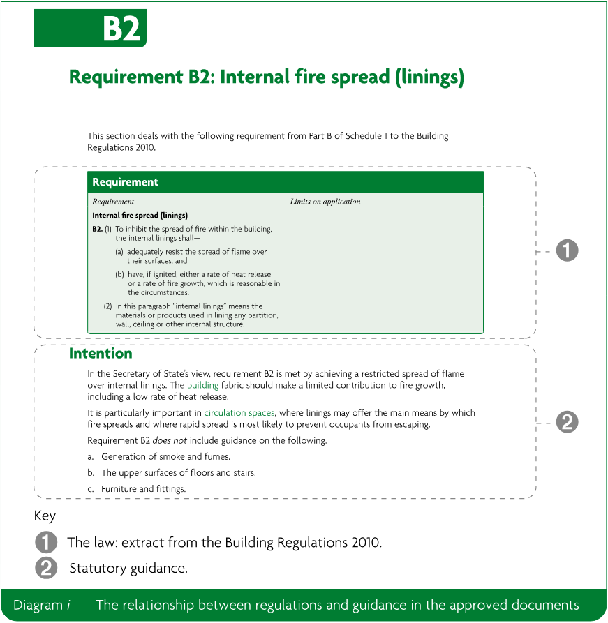
Anyone using the approved documents should have sufficient knowledge and skills to understand the guidance and correctly apply it to the building work. This is important because simply following the guidance does not guarantee that your building work will comply with the legal requirements of the Building Regulations. Each approved document contains legal requirements (which you must follow) and guidance (which you may or may not choose to follow). The text in a box with a green background at the beginning of each section of an approved document is taken from the Building Regulations. This text sets out the legal requirements.
The explanation which follows the legal requirements is guidance (see Diagram i below). The guidance then explains one or more ways to demonstrate how building work can be shown to comply with the legal requirements in common circumstances. The terms in green lettering in an approved document are key terms, listed and explained in the appendix to that approved document. Guidance in the approved documents addresses most, but not all, situations that building owners will face. Situations may arise that are not covered. You or your advisers will need to carefully consider whether following the guidance will mean that the requirements of the Building Regulations will be met.
Requirement B2: Internal fire spread (linings)
#Source page 6
This section deals with the following requirement from Part B of Schedule 1 to the Building Regulations 2010.
| Requirement | Limits on application |
|---|---|
| Internal fire spread (linings) B2. (1) To inhibit the spread of fire within the building, the internal linings shall— (a) adequately resist the spread of flame over their surfaces; and (b) have, if ignited, either a rate of heat release or a rate of fire growth, which is reasonable in the circumstances. (2) In this paragraph “internal linings” means the materials or products used in lining any partition, wall, ceiling or other internal structure. |
Intention
In the Secretary of State’s view, requirement B2 is met by achieving a restricted spread of flame over internal linings. The building fabric should make a limited contribution to fire growth, including a low rate of heat release.
It is particularly important in circulation spaces, where linings may offer the main means by which fire spreads and where rapid spread is most likely to prevent occupants from escaping.
Requirement B2 does not include guidance on the following.
a.Generation of smoke and fumes.
b.The upper surfaces of floors and stairs.
c.Furniture and fittings.
For further information about the use of technical guidance, see Chapter 7 in Volume 1 and Chapter F in Volume 2 of the Manual to the Building Regulations.
Where to get further help
If you are unsure whether you have the knowledge and skills to apply the guidance correctly, or if you do not understand the technical guidance or other information in this approved document or the additional detailed technical references to which it directs you, you should seek further help. Some sources of help are listed below.
a.Your building control body may be able to help in many cases.
b.If you are registered with a competent person scheme, the scheme operator should be in a position to help.
c.Suitably qualified and experienced construction professionals should also be engaged where necessary.
Contents
#Source page 7
Introduction
What is an approved document? — i
How is construction regulated in England? — i
How do you comply with the Building Regulations? — i
What do the Building Regulations cover? — ii
When must a building control body be notified? — ii
How to use this approved document — iii
Where to get further help — iv
Section 0: Introduction — 1
Summary — 1
Application — 2
Selected key interactions with other parts of the Building Regulations — 5
Regulations 24, 25, 25B, 26, 26C, 27 and 27C: Energy performance of building calculations — 6
Intention — 8
Section 1: Calculating the target primary energy rate and target emission rate — 9
Section 2: Calculating the building primary energy rate and building emission rate — 10
Building control notification — 10
Heating in the building primary energy rate and the building emission rate calculations — 11
Management and control features in the building primary energy rate and the building emission rate calculations — 12
Achieving the target primary energy rate and target emission rate — 13
Special considerations when calculating building primary energy rate and building emission rate — 13
Buildings with low energy demand — 17
Regulation 25A: Consideration of high-efficiency alternative systems — 18
Intention — 19
Section 3: Consideration of high-efficiency alternative systems — 20
Requirement L1(a): Limiting heat gains and losses — 21
Intention — 21
Section 4: Limiting heat gains and losses — 23
#Source page 8
U-values — 23
Limiting standards for new or replacement elements — 24
Limiting standards for renovated and retained elements — 26
Continuity of insulation — 27
Airtightness in existing buildings — 28
Limiting the effects of solar gains in summer — 29
Limiting heat losses and gains from building services — 29
Requirements L1(b)(i), (ii) and L2: Fixed building services energy efficiency and controls and on-site generation of electricity — 33
Intention — 34
Section 5: Minimum building services efficiencies and controls – general guidance — 35
New building services — 35
Replacement building services in existing buildings — 35
Sizing new and replacement space heating systems — 36
Controls and zoning for new and replacement space heating systems — 37
System treatment for hot water systems for space and domestic hot water heating — 37
Thermostatic room controls — 37
Energy submeters — 38
Section 6: System specific guidance — 39
Boilers — 39
Gas and oil-fired warm air heaters — 42
Gas and oil-fired radiant heaters — 42
Electric space heating systems — 43
Combined heat and power — 44
Dedicated domestic hot water heaters — 44
Comfort cooling — 47
Heating and cooling system circulators and water pumps — 49
Heat pumps — 49
Mechanical ventilation — 50
Heat recovery — 52
Lighting — 52
Building automation and control systems — 53
On-site electricity generation and storage — 55
District heat networks and community heating — 55
Regulation 43: Pressure testing
#Source page 9
Intention
Section 7: Air permeability and pressure testing
Showing compliance and reporting pressure test results
Air pressure testing procedure
Regulations 44 and 44ZA and requirements L1(b)(iii) and L2(b): Commissioning
Intention
Section 8: Commissioning
Notice of completion
Air leakage testing of ductwork
Regulations 40 and 40A: Providing information
Intention
Section 9: Providing information
Operating and maintenance instructions
Additional information for new buildings
Additional information for work in existing buildings
Regulation 23(2) and requirement L1(a): Replacement of thermal elements and limiting heat gains and losses
Intention
Section 10: New elements in existing buildings, including extensions
General
New and replacement thermal elements
New and replacement windows, roof windows, rooflights and doors (controlled fittings)
Extension of buildings other than dwellings
Conservatories and porches
Regulation 23(1) and requirement L1(a): Renovating elements and limiting heat gains and losses
Intention
Regulations 6 and 22: Material change of use and change to energy status
Intention
Section 11: Work to fabric elements in existing buildings
General
Renovating thermal elements
Material change of use and change to energy status
Regulation 28: Consequential improvements to energy performance
#Source page 10
Intention
Section 12: Consequential improvements
Consequential improvements which apply when extending a building
Consequential improvements on installing or extending the capacity of fixed building services
Appendix A: Key terms
Appendix B: Lighting Energy Numeric Indicator (LENI)
Appendix C: Reporting evidence of compliance
BRUKL report
Appendix D: Measures for consequential improvements
Appendix E: Hierarchy for establishing seasonal efficiencies of existing boilers
Appendix F: Standards referred to
Appendix G: Documents referred to
Legislation
Documents
Section 0: Introduction
#Source page 11
Summary
0.1This approved document is Approved Document L, Volume 2: Buildings other than dwellings. It gives guidance on how to comply with Part L of Schedule 1 to the Building Regulations and the energy efficiency requirements for buildings other than dwellings. For guidance relating to domestic buildings, use Approved Document L, Volume 1: Dwellings.
0.2This approved document contains the following sections:
| Approved document section | Related Building Regulations requirements |
|---|---|
| Section 0: Introduction | n/a |
| Section 1: Calculating the target primary energy rate and target emission rate | Regulations 24, 25, 25B, 26, 26C, 27 and 27C |
| Section 2: Calculating the building primary energy rate and building emission rate | |
| Section 3: Consideration of high-efficiency alternative systems | Regulation 25A |
| Section 4: Limiting heat gains and losses | Requirement L1(a) of Schedule 1 |
| Section 5: Minimum building services efficiencies and controls – general guidance | Requirements L1(b)(i), (ii) and L2 of Schedule 1 |
| Section 6: System specific guidance | |
| Section 7: Air permeability and pressure testing | Regulation 43 |
| Section 8: Commissioning | Regulations 44 and 44ZA and requirements L1(b)(iii) and L2(b) of Schedule 1 |
| Section 9: Providing information | Regulations 40 and 40A |
| Section 10: New elements in existing buildings, including extensions | Regulation 23(2) and requirement L1(a) of Schedule 1 |
| Section 11: Work to elements in existing buildings | Regulations 6, 22 and 23(1) and requirement L1(a) of Schedule 1 |
| Section 12: Consequential improvements | Regulation 28 |
| Appendix A: Key terms | n/a |
| Appendix B: Lighting Energy Numeric Indicator (LENI) | n/a |
| Appendix C: Reporting evidence of compliance | n/a |
| Appendix D: Measures for consequential improvements | n/a |
| Appendix E: Hierarchy for establishing seasonal efficiencies of existing boilers | n/a |
| Appendix F: Standards referred to | n/a |
| Appendix G: Documents referred to | n/a |
Application
#Source page 12
0.3The guidance in Approved Document L, Volume 2 applies only to buildings other than dwellings. In a mixed-use building, this document should be consulted for building work in those parts of the building that are not dwellings. This document gives guidance for building work in both new and existing buildings.
a.Rooms for residential purposes.
b.Buildings that contain only rooms for residential purposes.
For dwellings, Approved Document L, Volume 1: Dwellings applies.
0.4In the Secretary of State’s view, for the purposes of the energy efficiency requirements of the Building Regulations, a building means either of the following.
a.The whole of the building.
b.Part of a building designed or altered to be used as a separate premises.
Common areas in buildings that contain multiple dwellings
0.5For the common areas of buildings that contain more than one dwelling, the following guidance applies.
a.If the common areas are heated, the guidance in this approved document should be followed.
b.If the common areas are unheated, individual fabric elements should meet the minimum standards set out in Section 4 of Approved Document L, Volume 1: Dwellings.
New buildings
0.6Guidance for new buildings is given in Sections 1 to 9 of this approved document, Approved Document L, Volume 2.
0.7For a conservatory or porch installed as part of the construction of a new building, the treatment of the conservatory or porch depends on whether both of the following have been achieved.
a.There is adequate thermal separation between the building and the conservatory or porch.
b.The building’s heating system is not extended into the conservatory or porch.
If both (a) and (b) have been achieved, the conservatory or porch should be treated as if it were an extension being added onto an existing building. The guidance for new elements in existing buildings in Section 10 should be followed.
If either or both of (a) or (b) has not been achieved, the conservatory or porch should be treated as a room in the new building. The guidance for the whole new building should be followed, including for building primary energy rate and building emission rate calculations.
0.8For the first fit-out works in buildings, such as shell-and-core office buildings, guidance for new buildings covering first fit-out should be followed. For any subsequent fit-out works the guidance for existing buildings should be followed.
0.9For constructing a building from modular subassemblies, or for relocating a modular or portable building, the guidance for new buildings should be followed, taking note of the special considerations for these building types outlined in Section 2. If the work extends an existing building, consequential improvements may also be required. Guidance is given in Section 12.
Extensions to and work on existing buildings
#Source page 13
0.10Guidance for existing buildings is given in this approved document for the following.
a.Limiting heat gains and losses: Section 4.
b.Building services: Sections 5 and 6.
c.New elements in existing buildings, including replacing a thermal element and constructing an extension: Section 10.
d.Existing elements in existing buildings, including renovating or retaining a thermal element, material change of use and change to energy status: Section 11.
e.consequential improvements: Section 12.
Exemptions
0.11The following classes of buildings or parts of buildings other than dwellings are exempt from the energy efficiency requirements.
a.Places of worship – buildings or parts of a building that are used primarily or solely for formal public worship, plus adjoining spaces the function of which is directly linked to that use (e.g. a vestry in a church).
b.Temporary buildings with a total planned time of use of two years or less.
c.Buildings with low energy demand which are industrial sites, workshops or non-residential agricultural buildings.
d.New and existing stand-alone buildings other than dwellings, with a total useful floor area of less than 50m².
e.Carports, covered yards, covered ways and some conservatories and porches (see paragraphs 0.18 to 0.19).
Exemptions for listed buildings, buildings in conservation areas and scheduled monuments
0.12Work to the following types of buildings does not need to comply fully with the energy efficiency requirements where to do so would unacceptably alter the building’s character or appearance.
a.Those listed in accordance with section 1 of the Planning (Listed Buildings and Conservation Areas) Act 1990.
b.Those in a conservation area designated in accordance with section 69 of the Planning (Listed Buildings and Conservation Areas) Act 1990.
c.Those included in the schedule of monuments maintained under section 1 of the Ancient Monuments and Archaeological Areas Act 1979.
Historic and traditional buildings
#Source page 14
0.13Work to a building in paragraph 0.12 must comply with the energy efficiency requirements where this would not unacceptably alter the building’s character or appearance. The work should comply with standards in this approved document to the extent that it is reasonably practicable.
Historic and traditional buildings
0.14The energy efficiency of historic and traditional buildings should be improved only if doing so will not cause long-term deterioration of the building’s fabric or fittings. In particular, this applies to historic and traditional buildings with a vapour permeable construction that both absorbs moisture and readily allow moisture to evaporate. Examples include those built with wattle and daub, cob or stone and constructions using lime render or mortar.
0.15New extensions to historic or traditional buildings should comply fully with the energy efficiency standards in this approved document unless there is a need to match the external appearance or character of the extension to that of the host building. The work should comply with standards in this approved document to the extent that it is reasonably practicable.
0.16In determining whether full energy efficiency improvements should be made, the building control body should consider the advice of the local authority’s conservation officer.
0.17Additional guidance is available in Historic England’s Energy Efficiency in Historic Buildings: Application of Part L of the Building Regulations to Historic and Traditionally Constructed Buildings.
Exemptions for conservatories and porches
0.18Where a building is extended by adding a conservatory or porch, the work is exempt from the energy efficiency requirements, under regulation 21 of the Building Regulations, if all of the following apply.
a.The extension is at ground level.
b.The floor area of the extension does not exceed 30m².
c.The glazing complies with Part K of Schedule 1 to the Building Regulations.
d.Any wall, door or window that separates the extension from the building has been retained or, if removed, replaced with a wall, door or window.
e.The heating system of the building is not extended into the conservatory or porch.
Exemptions for covered areas
0.19Where a building is extended by adding a carport that is open on at least two sides, a covered yard, covered walkway or covered driveway, the work is exempt from the energy efficiency requirements if both of the following apply.
a.The extension is at ground level.
b.The floor area of the extension does not exceed 30m².
Live/work units
0.20A building that contains both living accommodation and space for commercial purposes (e.g. for a workshop or office) should be treated as a dwelling if the commercial part can be reverted to domestic use. Guidance for dwellings can be found in Approved Document L, Volume 1: Dwellings.
0.21The commercial part of a building can be reverted to domestic use if all of the following apply.
a.There is direct access between the commercial space and the living accommodation.
Mixed-use developments
#Source page 15
b.The commercial space and the living accommodation are within the same thermal envelope.
c.The living accommodation comprises a substantial proportion of the total area of the unit. What constitutes a ‘substantial proportion’ should be assessed on a case-by-case basis by the building control body.
Mixed-use developments
0.22When constructing a building that contains dwellings and other types of accommodation, sometimes called a mixed-use development, refer to the two volumes of Approved Document L as follows.
a.For guidance on each individual dwelling, use Approved Document L, Volume 1: Dwellings.
b.For guidance on the non-dwelling parts of the building, such as heated common areas and any commercial or retail space, use this approved document.
Selected key interactions with other parts of the Building Regulations
0.23The approved documents set out what, in ordinary circumstances, may be accepted as one way to comply with the Building Regulations. Those designing or undertaking building work remain responsible for assessing, on a case-by-case basis, whether specific circumstances require additional or alternative measures to achieve compliance with the regulatory requirements. There are interactions between many of the requirements of the Building Regulations. Guidance on some key interactions is given below.
Interaction with Part C
0.24This approved document, Approved Document L, Volume 2, provides guidance and examples on upgrading thermal elements. For interstitial and surface condensation, a lesser standard may be acceptable. Guidance in Approved Document C should be followed.
Interaction with Part E
0.25This approved document, Approved Document L, Volume 2, provides guidance on insulation that is reasonably continuous and limits thermal bridging. Construction junctions should limit noise transfer where Part E of the Building Regulations sets a requirement. Approved Document E should be followed.
Interaction with Part F
0.26This approved document, Approved Document L, Volume 2, provides guidance on reducing unwanted heat loss, by achieving optimum airtightness. When specifying the minimum amount of purpose-provided ventilation, consider the air infiltration of a building; follow Approved Document F.
Interaction with Part J
0.27This approved document, Approved Document L, Volume 2, provides guidance on airtightness. For guidance on permanent ventilation openings for open flued appliances in very airtight buildings, follow Approved Document J.
Interaction with Part K and Part M
0.28This approved document, Approved Document L, Volume 2, provides guidance on controls for fixed building services and on-site electricity generation. Manual controls, where provided, should be within reasonable reach of the occupants. Follow the guidance in Approved Documents K and M.
Regulations 24, 25, 25B, 26, 26C, 27 and 27C: Energy performance of building calculations
#Source page 16
This section deals with the requirements of regulations 24, 25, 25B, 26, 26C, 27 and 27C of the Building Regulations 2010.
Regulation continued
#Source page 17
CO₂ emission rate calculations
27. (1)This regulation applies where a building is erected and regulation 26 applies.
(2)Not later than the day before the work starts, the person carrying out the work shall give the local authority a notice which specifies—
(a)the target CO₂ emission rate for the building, calculated and expressed in accordance with the methodology approved pursuant to regulation 24,
(b)the CO₂ emission rate for the building as designed, calculated and expressed in accordance with the methodology approved pursuant to regulation 24, and
(c)a list of specifications to which the building is to be constructed.
(3)Not later than five days after the work has been completed, the person carrying out the work shall give the local authority—
(a)a notice which specifies—
(i)the target CO₂ emission rate for the building, calculated and expressed in accordance with the methodology approved pursuant to regulation 24,
(ii)the CO₂ emission rate for the building as constructed, calculated and expressed in accordance with the methodology approved pursuant to regulation 24, and
(iii)whether the building has been constructed in accordance with the list of specifications referred to in paragraph (2)(c), and if not a list of any changes to those specifications; or
(b)a certificate of the sort referred to in paragraph (4) accompanied by the information referred to in sub-paragraph (a).
(4)A local authority are authorised to accept, as evidence that the requirements of regulation 26 have been satisfied, a certificate to that effect by an energy assessor who is accredited to produce energy performance certificates for that category of building.
(5)In this regulation, “specifications” means specifications used for the calculation of the CO₂ emission rate.
Target primary energy rate calculations for new buildings
27C. (1)This regulation applies where a building is erected.
(2)Not later than the day before the work starts, the person carrying out the work must give the local authority a notice which specifies—
(a)the target primary energy rate for the building calculated and expressed in accordance with the methodology approved pursuant to regulation 24;
(b)the calculated target primary energy rate for the building as designed, calculated and expressed in accordance with the methodology approved pursuant to regulation 24; and
(c)the list of specifications to which the building is to be constructed.
(3)Not later than five days after the work has been completed, the person carrying out the work must give the local authority—
(a)a notice which specifies—
(i)the target primary energy rate for the building calculated and expressed in accordance with the methodology approved pursuant to regulation 24;
(ii)the calculated target primary energy rate for the building as constructed, calculated and expressed in accordance with the methodology approved pursuant to regulation 24; and
(iii)whether the building has been constructed in accordance with the list of specifications referred to in paragraph (2)(c), and if not a list of any changes to those specifications; or
(b)a certificate of the sort referred to in paragraph (4) accompanied by the information referred to in sub-paragraph (a).
(4)A local authority is authorised to accept, as evidence that the requirements of regulation 26C have been satisfied, a certificate to that effect by an energy assessor who is accredited to produce energy performance certificates for that category of building.
(5)In this regulation, “specifications” means specifications used for the calculation of the target primary energy rate.
Intention
#Source page 18
Intention
Regulation 24
Regulation 24 requires the Secretary of State to approve a methodology of calculation of the energy performance of a building. Approved tools for implementing this methodology for new non-domestic buildings are the Simplified Building Energy Model or other software tools approved under the Notice of Approval.
Calculation methodologies are set out in Section 1 and Section 2 of this approved document.
Regulation 25
Regulation 25 requires the Secretary of State to approve minimum energy performance requirements. These requirements are in the form of a target primary energy rate and a target emission rate.
The targets are set out in Section 1 of this approved document.
Regulation 25B
The Secretary of State considers that a building has a very high performance rate for the purposes of the definition of a nearly zero-energy building if both of the following are met.
a.The building meets the target emission rate required under regulation 26.
b.Both:
i.An analysis is made of the technical, environmental and economic feasibility of using high efficiency alternative systems, which include decentralised energy supply systems based on energy from renewable sources.
ii.This analysis is considered as required by regulation 25A.
Regulations 26 and 26C
A newly constructed building must be shown to meet regulations 26 and 26C by producing calculations to show that the building meets both of the following.
a.Target primary energy rate.
b.Target emission rate.
Section 2 of this approved document sets out how to produce these calculations.
Regulations 27 and 27C
Both before and after a newly constructed building is built, a notice must be given to the building control body of the calculations.
Section 1: Calculating the target primary energy rate and target emission rate
#Source page 19
1.1A new building must be built to a minimum standard of total energy performance. This is evaluated by comparing calculations of the performance of the ‘actual building’ against calculations of the performance of a theoretical building, called the ‘notional building’. This must be carried out both at the design stage and when work is complete.
The notional building is the same size and shape as the actual building and has standardised properties for fabric and services. The full properties of the notional building are set out in the National Calculation Methodology Modelling Guide, which is available from https://www.uk-ncm.org.uk/.
1.2The energy performance of the notional building is described using the following metrics.
a.The target primary energy rate, in kWhₚₑ/m² per year.
b.The target emission rate, in kgCO₂/m² per year.
1.3The target primary energy rate and target emission rate must be calculated using one of the calculation tools in the approved methodology, used in line with the version policy as stated in the methodology. As part of the submission to the building control body, the applicant should show that the software tool used is appropriate to the application. The calculation tool can be either of the following.
a.The Simplified Building Energy Model (SBEM), for buildings with design features that are capable of being adequately modelled by the Simplified Building Energy Model.
b.Other software tools approved under the Notice of Approval.
Section 2: Calculating the building primary energy rate and building emission rate
#Source page 20
2.1The same approved calculation tool must be used to calculate the target primary energy rate, the target emission rate, the building primary energy rate and the building emission rate.
2.2The building primary energy rate and the building emission rate must be calculated at both of the following points using the same calculation tool.
a.Before work starts, using design values.
b.When work is complete, using figures for the building as constructed, and incorporating both of the following.
i.Any changes that have been made during construction to the list of specifications.
ii.The measured air permeability.
2.3At both of these points the building primary energy rate and building emission rate must not exceed the target primary energy rate and the target emission rate, respectively. The specification of the actual building may vary from that of the notional building if the building meets the target primary energy rate, target emission rate and the guidance in this approved document.
Building control notification
2.4The building control body must be notified, before the work starts, of all of the following.
a.The target primary energy rate and the building primary energy rate (calculated using design values).
b.The target emission rate and the building emission rate (calculated using design values).
c.A list of specifications used in the calculations.
Items (a) to (c) above may be reported using the design stage Building Regulations UK Part L compliance report (BRUKL report) which is produced as a standardised output from the approved software. For further details of the design stage BRUKL report, see Appendix C.
2.5The building control body must be notified, once the work is complete, of all of the following.
a.The as-built target primary energy rate and as-built building primary energy rate.
b.The as-built target emission rate and the as-built building emission rate.
c.A list of specifications used in the as-built calculations, and whether the specifications have changed from those used in the design stage calculations.
Building control bodies are authorised to accept notification of (a) to (c) above as reported in the as-built BRUKL report, which is produced as a standardised output from the approved software. For further details of the as-built BRUKL report, see Appendix C.
Heating in the building primary energy rate and the building emission rate calculations
#Source page 21
2.6When systems are capable of being fired by more than one fuel, the following applies, according to the fuel(s).
a.Biomass heating supplemented by an alternative appliance (e.g. gas) – the CO₂ emission factor and primary energy factor should be based on a weighted average for the two fuels. The weighting should be based on the anticipated usage of those fuels. The building emission rate and building primary energy rate submission should be accompanied by a report, signed by a suitably qualified person, detailing how the combined emission factor has been derived.
b.Appliances capable of burning both biomass fuel and fossil fuel – the CO₂ emission factor and primary energy factor for dual-fuel appliances should be used, except where the building is in a smoke control area, when the anthracite figure should be used.
c.In all other cases, the fuel with the highest CO₂ emission factor should be used.
2.7If thermal energy is supplied from a district heat network or community heating system or community cooling system, CO₂ emission factors and primary energy factors should be determined by considering the details of the scheme and following the guidance in items (a) to (g) below.
a.The CO₂ emission factor and primary energy factor for the heat delivered to the building by the district heat network should be based on the ‘heat network’ specific factors from Table 32 in the National Calculation Methodology Modelling Guide.
b.Calculations should take account of the annual average performance of the whole system, including the distribution circuits, all heat generating plants, combined heat and power (CHP), and any waste heat recovery or heat dumping.
c.The calculation should include the predicted effect of all buildings or parts of buildings that will be connected to the system in the first 12 months of operation. A change in the number of buildings or spaces within buildings connected to the system might affect the percentage of heat supplied from the communal system. The increased operation of any marginal plant (e.g. gas boilers) can then be properly accounted for.
d.The electricity generated by any combined heat and power (CHP) or trigeneration scheme should always be credited using the appropriate CO₂ emission and primary energy ‘heat network’ specific factors from Table 32 in the National Calculation Methodology Modelling Guide.
e.CO₂ emissions and primary energy associated with the thermal energy streams of a trigeneration scheme should be attributed in proportion to the output energy streams.
f.When calculating the building primary energy rate and building emission rate for a building connected to a new district heat network, the calculation should include all heat sources to be used up to 31 December 2027. In this way, any planned transition of the heat network to an alternative means of heat generation will be properly accounted for. When there will be a change in heat source up to 31 December 2027, a submission to the building control body should be made to show both of the following.
i.That planning permission, if required, has been granted for the change.
ii.That the heat network will connect to the new source, with confirmation in the form of a signed contract to connect and supply heat.
Management and control features in the building primary energy rate and the building emission rate calculations
#Source page 22
g.The building primary energy rate and building emission rate submission should be accompanied by a report, signed by a suitably qualified person, detailing how the CO₂ emission factors and primary energy factors have been derived.
The primary energy factor for the heat output should be taken as:
1⁄H × (F × PEᶠ − E × PEᴱ)
where:
H is the useful heat (excluding heat rejected) in kWh
F is the fuel input in kWh
PEᶠ is the primary energy factor for the input fuel in kWhₚₑ/kWh
E is the electricity production from the scheme in kWh
PEᴱ is the primary energy factor for district heat CHP generated electricity in kWhₚₑ/kWh.
The CO₂ emission factor for the heat output should be taken as:
1⁄H × (F × CO₂ᶠ − E × CO₂ᴱ)
where:
H is the useful heat (excluding heat rejected) in kWh
F is the fuel input in kWh
CO₂ᶠ is the emission factor for the input fuel in kgCO₂/kWh
E is the electricity production from the scheme in kWh
CO₂ᴱ is the emission factor for district heat CHP generated electricity in kgCO₂/kWh.
Management and control features in the building primary energy rate and the building emission rate calculations
2.8Where enhanced management and control features are provided in the building, the building primary energy rate and building emission rate can be reduced. This is done by applying the appropriate factor given in Table 2.1 to both of the following, for the system(s) to which the feature is being applied.
a.The CO₂ emissions.
b.The primary energy.
Achieving the target primary energy rate and target emission rate
#Source page 23
| Feature | Adjustment factor |
|---|---|
| Automatic monitoring and targeting with alarms for out-of-range values(1) | 0.050 |
| Power factor correction to achieve a whole building power factor >0.90(2) | 0.010 |
| Power factor correction to achieve a whole building power factor >0.95(2) | 0.025 |
NOTES:
1. This means a complete installation that measures, records, transmits, analyses, reports and communicates meaningful energy management information to enable the operator to manage the energy it uses. A building automation and control system specified following paragraphs 6.66 to 6.73 would meet this definition.
2. The power factor adjustment can be made only if the whole building power factor is corrected to achieve the value in this table (>0.90 or >0.95). The two levels of power factor correction are alternative values, not additive.
Achieving the target primary energy rate and target emission rate
2.9Provided the building satisfies the minimum standards for fabric elements set out in Section 4, the designer can achieve the target primary energy rate and target emission rate by using any combination of the following.
a.Fabric energy efficiency.
b.Efficient building services.
c.Low and zero carbon technologies integrated in an appropriate mix.
Special considerations when calculating building primary energy rate and building emission rate
2.10Special considerations may apply to certain classes of building. These building types include all of the following.
a.Modular and portable buildings with a planned service life of more than two years (at one or more sites), follow paragraphs 2.11 to 2.19.
b.Swimming pools, follow paragraph 2.20.
c.Shell and core developments, follow paragraphs 2.21 to 2.25.
d.Industrial sites, workshops and non-residential agricultural buildings, follow paragraph 2.26.
e.Buildings with low energy demand, follow paragraphs 2.27 to 2.32.
Modular and portable buildings with a planned service life of more than two years
#Source page 24
2.11Placing an existing module on a new site is considered by the Building Regulations to be the construction of a new building.
2.12Special considerations apply to modular and portable buildings with a planned service life of more than two years.
a.For modular and portable buildings at a single location, follow paragraphs 2.13 to 2.15.
b.For modular and portable buildings intended for use at more than one location, for example under hire agreements, follow paragraphs 2.16 to 2.19.
At a single location
2.13Modular and portable buildings with a planned service life of more than two years at a single location should be shown to comply with the energy efficiency requirements.
2.14If more than 70% of the external envelope of this type of building will be created from sub-assemblies manufactured before the date when this approved document came into force, the target primary energy rate and target emission rate should be multiplied by the relevant factors from Table 2.2.
2.15After initial manufacture, any work on a module should meet the standards in this document, treating it as work on an existing building. Fabric elements that will be refurbished or replaced in modular sub-assemblies should meet the minimum standards given in Section 4. Fixed building services elements that will be replaced in modular sub-assemblies should meet the minimum standards in Sections 5 and 6.
| Date of manufacture of 70% of modules making up the external envelope | Target primary energy rate multiplying factor | Target emission rate multiplying factor |
|---|---|---|
| After the coming into force date | 1.00 | 1.00 |
| 6 April 2014 – coming into force date | 1.30 | 1.30 |
| 1 October 2010 – 5 April 2014 | 1.40 | 1.40 |
| 6 April 2006 – 30 September 2010 | 1.67 | 1.67 |
| Pre 6 April 2006 | 1.67 | 1.67 |
At more than one location
2.16Modular and portable buildings with a planned service life of more than two years but with an intended time of use in a single location of less than two years should be shown to comply with the energy efficiency requirements. An example of this type of building would be a modular or portable building intended for short term hire to multiple locations.
Swimming pool basins
#Source page 25
2.17For modular or portable buildings of the type described in paragraph 2.16, a target primary energy rate and building primary energy rate calculation and target emission rate and building emission rate calculation should be carried out when the portable building or its modular components are first constructed. The calculation can be based on a standard generic configuration of modules.
Whenever the building is moved to a new location, in which its intended time of use is less than two years, these calculations can be provided as evidence that the energy efficiency requirements are met. The supplier should provide all the following in writing.
a.Details of the calculation.
b.Confirmation that the modules as provided meet or exceed the elemental energy standards of the generic module on which the calculation was based.
c.Confirmation that the activities assumed in the generic module are reasonably representative of the planned use of the actual module.
2.18If the planned time of use of a modular or portable building in a single location is less than two years, the only practical heating technology may be electric resistance heating. In such cases, the notional building will use electric resistance heating.
2.19If more than 70% of the external envelope of this type of building will be created from sub-assemblies manufactured before the date when this approved document came into force, the target primary energy rate and target emission rate should be multiplied by the relevant factors from Table 2.3.
| Date of manufacture of 70% of modules making up the external envelope | Target primary energy rate multiplying factor | Target emission rate multiplying factor |
|---|---|---|
| After the coming into force date | 1.00 | 1.00 |
| 6 April 2014 – coming into force date | 1.30 | 1.30 |
| 1 Oct 2010 – 5 April 2014 | 1.40 | 1.40 |
| 6 April 2006 – 30 Sept 2010 | 1.67 | 1.67 |
| Pre 6 April 2006 | 2.03 | 2.03 |
Swimming pool basins
2.20When calculating the building primary energy rate and building emission rate for a building with a swimming pool, the thermal performance of the pool basin should not be included in the calculation. Instead, the building primary energy rate and building emission rate should be calculated as if the area covered by the pool were replaced with the equivalent area of floor with the same U-value as the pool surround.
Shell and core developments
#Source page 26
2.21If a building is offered to the market as a shell for fit-out work by the incoming occupier, the developer should calculate a design-stage target primary energy rate, building primary energy rate, target emission rate and building emission rate. These calculations should be submitted to the building control body. The submission should demonstrate how the building could reasonably meet the energy efficiency requirements after fit-out.
2.22If some systems are not installed when a building is put on the market, reasonable assumptions should be made in the calculation of the building primary energy rate and building emission rate and model for the efficiencies of services that will be installed during first fit-out work. The specification provided to the building control body should include all of the following.
a.Details of the services, including any on-site electricity generation, not provided in the base build.
b.The efficiency values assumed for these services.
c.A statement on how access to install any services, including on-site electricity generation, will be provided during first fit-out work.
2.23At practical completion of the base building in a shell and core development, the as-built target primary energy rate, building primary energy rate, target emission rate and building emission rate calculations should be based only on the building and systems as constructed; the fit-out areas should be assumed to be conditioned to temperatures appropriate to their designated use, but no associated energy demand included.
2.24If an incoming occupier does first fit-out work on all or part of a building in a shell and core development by providing or extending fixed services for any of the following:
a.heating
b.hot water
c.air-conditioning
d.mechanical ventilation
then a target primary energy rate, building primary energy rate, target emission rate and building emission rate submission should be made to the building control body after completion to demonstrate compliance for the part of the building covered by the fit-out work.
2.25If fit-out work does not include providing or extending any of the fixed services for any of the following:
a.heating
b.hot water
c.air-conditioning
d.mechanical ventilation
then any lighting systems that are installed should be at least as efficient as those assumed in the shell developer’s initial submission.
Industrial sites, workshops and non-residential agricultural buildings other than those with low energy demand
#Source page 27
2.26Special considerations may apply for industrial sites, workshops and non-residential agricultural buildings, where the National Calculation Methodology Modelling Guide cannot adequately account for the building’s use. For example, if using the National Calculation Methodology Modelling Guide would lead to negative impacts on cost-effectiveness and/or significant technical risk.
Buildings with low energy demand
2.27Buildings with low energy demand are taken to be buildings or parts of buildings, which are not exempt from the energy efficiency requirements for reasons outlined in Section 0, where any of the following apply.
a.Fixed building services for heating and/or cooling are not provided.
b.Fixed building services for heating and/or cooling are provided only to heat or cool a localised area rather than the entire enclosed volume of the space concerned (e.g. localised radiant heaters at a workstation in a generally unheated space).
c.Fixed building services are used to heat space in the building to temperatures that are substantially lower than those normally provided for human comfort (e.g. to protect a warehouse from frost).
2.28A target primary energy rate, target emission rate, building primary energy rate and the building emission rate should be calculated for non-exempt buildings with low energy demand. Zones corresponding to the definitions in paragraph 2.27 should be modelled as outlined in the National Calculation Methodology Modelling Guide paragraph 124 as ‘unconditioned’, i.e. not served by a space heating or space cooling system.
2.29For a building with low energy demand both of the following apply.
a.Every fixed building service that is installed should meet the energy efficiency standards set out in Sections 5 and 6.
b.The building envelope should be insulated to a degree that is reasonable in the particular case. If some general heating is provided, as in paragraph 2.27c, then no part of the opaque fabric should have a U-value worse than 0.7W/(m²·K).
2.30If part of a building with low energy demand is both:
a.partitioned off
b.heated normally
(for example, an office area in an unheated warehouse), then the separately heated area should be treated as a separate building or zone and the normal procedures for demonstrating compliance should be followed.
2.31If a building with low energy demand subsequently changes to a building that no longer has a low energy demand, consequential improvements may need to be made in some circumstances. See Section 12.
2.32If a building or part of a building with low energy demand was designed as a shell and core building, and first fit-out work is carried out which results in it no longer being classed as low energy demand (in line with paragraph 2.24), then normal procedures for demonstrating compliance should be followed.
Regulation 25A: Consideration of high-efficiency alternative systems
#Source page 28
This section deals with the requirements of regulation 25A of the Building Regulations 2010.
Intention
#Source page 29
Intention
In the Secretary of State’s view, regulation 25A is met in a new building by analysing the feasibility of installing high-efficiency alternative systems, following Section 3.
The Building Regulations do not require that high-efficiency alternative systems or other low or zero carbon systems are installed.
Section 3: Consideration of high-efficiency alternative systems
#Source page 30
3.1Before building work starts on a new non-domestic building, the person undertaking the building work must analyse the technical, environmental and economic feasibility of using high-efficiency alternative systems in the building design. This analysis should be considered when designing the building.
3.2The building control body should be notified that the analysis of high-efficiency alternative systems has been undertaken, that it is documented and is available to be verified. The document should state whether high-efficiency alternative systems have been included in the building design. The documented results of the analysis should be retained for the building control body to inspect upon request.
3.3The analysis may be carried out for individual buildings, groups of similar buildings, or for common types of buildings in the same area. Where a number of buildings are connected to a district heat network or community heating system, a single analysis may be made for all buildings connected to the network or system.
3.4When a building undergoes a major renovation, the technical, environmental and economic feasibility of installing high-efficiency alternative systems should be considered.
Requirement L1(a): Limiting heat gains and losses
#Source page 31
This section deals with the requirements of Part L1(a) of Schedule 1 to the Building Regulations 2010.
| Requirement | Limits on application |
|---|---|
| Schedule 1 – Part L Conservation of fuel and power L1. Reasonable provision shall be made for the conservation of fuel and power in buildings by— (a) limiting heat gains and losses— (i) through thermal elements and other parts of the building fabric; and (ii) from pipes, ducts and vessels used for space heating, space cooling and hot water services; (b) providing fixed building services which— (i) are energy efficient to a reasonable standard; (ii) have effective controls; and (iii) are commissioned by testing and adjusting as necessary to ensure they use no more fuel and power than is reasonable in the circumstances. |
Intention
In the Secretary of State’s view, requirement L1(a) is met in a new building by achieving both of the following:
a.Unwanted heat losses from the building are limited by meeting the standards for all of the following.
i.The building fabric, including walls, floors, roof, windows and openings – paragraphs 4.1 to 4.6 and paragraphs 4.9 to 4.14.
ii.Airtightness – the required air permeability from Table 4.1.
iii.The pipework and services – paragraphs 4.19 to 4.25.
b.Unwanted heat gains to the building, throughout the year, through any of the routes listed in (a) above, are limited as set out in Section 4 and specifically for new buildings – paragraphs 4.16 to 4.18.
Page 32
#Source page 32
In the Secretary of State’s view, requirement L1(a) is met for the work being done to an existing building by achieving both of the following, where relevant to the work being done.
a.Unwanted heat losses from the building are limited by meeting the standards for all of the following.
i.Any building fabric to which building work is being done, including walls, floors, roof, windows and openings – paragraphs 4.1 to 4.14. Further guidance is given in the following sections.
•For new elements, replacement elements and extensions – Section 10.
•For renovated elements, retained elements, a change to energy status and a material change of use – Section 11.
ii.Any work that may result in making airtightness worse – paragraph 4.15.
iii.Any pipework and services to which building work is being done – paragraphs 4.19 to 4.25.
b.Unwanted heat gains to the building, throughout the year, through any of the routes listed in point (a) are limited as set out in Section 4.
Section 4: Limiting heat gains and losses
#Source page 33
U-values
4.1U-values should be assessed using the methods and conventions set out in the Building Research Establishment’s BR 443. U-values should be assessed for the whole thermal element (e.g. in the case of a window, the combined performance of the glazing and the frame).
4.2The U-value of a window should be assessed using one of the following methods.
a.Calculated using the actual size and configuration of the window.
b.For windows in buildings similar to dwellings, calculated for a standard window 1.23m (±25%) wide × 1.48m (−25%) high and the actual configuration of the window.
c.For windows in buildings similar to dwellings, calculated for a standard window 1.23m (±25%) wide × 1.48m (−25%) high and one of the following standard configurations. Standard configurations should not be used for commercial windows.
i.For a casement window, a central vertical divider with one opening light and one fixed light.
ii.For a vertical sliding sash window, a central horizontal divider with two opening lights.
iii.For a roof window, no divider.
d.Measured using the hot-box method as set out in BS EN ISO 12567-1 for windows and BS EN ISO 12567-2 for roof windows.
4.3The U-value of a door should be assessed using one of the following methods.
a.Calculated using the actual size and configuration of the door.
b.Calculated using one of the following standard sizes.
i.1.23m (±25%) wide × 2.18m (±25%) high, for doors ≤ 3.6 m².
ii.2.00m (±25%) wide × 2.18m (±25%) high, for doors > 3.6 m².
c.Measured using the hot-box method as set out in BS EN ISO 12567-1.
4.4To correctly assess whether an element meets the limiting U-value, the U-value must be calculated for the element in the appropriate plane – either horizontal or vertical. For windows and roof windows, U-values should be calculated based on a vertical position. For rooflights, U-values should be calculated based on a horizontal position. If the data available for the element is in the incorrect plane, it should be adjusted according to the guidance in the Building Research Establishment’s BR 443.
Limiting standards for new or replacement elements
#Source page 34
4.5New fabric elements should meet the limiting standards in Table 4.1. This includes all of the following.
a.Elements in new buildings.
b.New elements in extensions to existing buildings.
c.New or replacement elements in existing buildings.
Guidance on when a new or replacement element in an existing building must meet the requirements in this table is given in Section 10.
4.6If windows or fully glazed pedestrian doors cannot meet the requirements of Table 4.1 in an existing building because of the need to maintain the character of the building, either of the following should be met.
a.These fittings should not exceed a centre pane U-value of 1.2W/(m²·K).
b.Single glazing should be supplemented with low-emissivity secondary glazing.
Page 35
#Source page 35
| Element type | Maximum U-value(1) W/(m²·K) or air permeability |
|---|---|
| Roof (flat roof)(2) | 0.18 |
| Roof (pitched roof)(2) | 0.16 |
| Wall(2)(3) | 0.26 |
| Floor(4)(5) | 0.18 |
| Swimming pool basin(6) | 0.25 |
| Windows in buildings similar to dwellings(7)(8) | 1.6 or Window Energy Rating(9) Band B |
| All other windows,(8)(10)(11) roof windows, curtain walling | 1.6 |
| Rooflights(12)(13) | 2.2 |
| Pedestrian doors (including glazed doors)(14) | 1.6 |
| Vehicle access and similar large doors | 1.3 |
| High-usage entrance doors | 3.0 |
| Roof ventilators (including smoke vents) | 3.0 |
| Air permeability (for new buildings) | 8.0m³/(h·m²) @ 50Pa |
1. Area-weighted average values, except for new windows, rooflights and doors in existing buildings.
2. For dormer windows, ‘roof’ includes the roof parts of the windows and ‘wall’ includes the wall parts (cheeks).
3. If meeting such a standard in an existing building would reduce by more than 5% the internal floor area of the room bounded by the wall, a lesser provision may be appropriate.
4. The U-value of the floor of an extension may be calculated using the exposed perimeter and floor area of either the whole enlarged building or the extension alone.
5. If meeting such a standard in an existing building, would create significant problems in relation to adjoining floor levels, a lesser provision may be appropriate.
6. The U-value of a swimming pool basin (walls and floor) calculated according to BS EN ISO 13370.
7. For example, student accommodation, care homes and similar uses where the occupancy levels and internal heat gains are essentially domestic in character.
8. If other performance (e.g. wind load, safety, security or acoustic attenuation) requires thicker glass to be used, an equivalent window unit with standard thickness glazing should be shown to meet the required standard.
9. The methods for calculating Window Energy Rating are set out in the Glass and Glazing Federation’s Glazing Manual Data Sheet 2.3, Guide to the Calculation of Energy Ratings for Windows, Roof Windows and Doors.
10. No maximum U-value is set for display windows and similar glazing. There are no limits on the design of display windows and similar glazing, but for new buildings their impact must be taken into account in the calculation of primary energy and CO₂ emissions.
11. In buildings with high internal heat gains, the average U-value for windows can be relaxed from the values given above if this can be shown to be an appropriate way of reducing overall CO₂ emissions and primary energy. However, values should be no higher than 2.7W/(m²·K).
12. U-values for rooflights or rooflight-and-kerb assemblies should be based on the developed surface area of the rooflight (Uᵈ values), which is often greater than the area of the roof opening. Further guidance on Uᵈ-values is given in the Building Research Establishment’s BR 443 and the National Association of Rooflight Manufacturers’ Technical Document NTD02.
13. The limiting value for rooflights also applies to kerbs that are supplied as part of a single rooflight-and-kerb assembly sourced from the same supplier and for which the supplier can provide a combined U-value for the assembly. An upstand built on site should have a maximum U-value of 0.35W/m²·K.
14. For external fire doorsets, as defined in Appendix A of Approved Document B, Volume 2, in new and existing non-domestic buildings, a maximum U-value of 1.8W/(m²·K) is permissible.
Limiting standards for renovated and retained elements
#Source page 36
4.7Existing elements that are being renovated should meet the limiting standards in Table 4.2. Guidance on when an existing element should meet the standards in Table 4.2 is given in Section 11. Elements that should meet the standards include both of the following.
a.Thermal elements being renovated in existing buildings. Renovated elements should achieve the U-values in Table 4.2, column (b).
b.Elements being retained in existing buildings, for example following a material change of use or change to energy status (see Section 11). Retained elements with a U-value that is higher than the threshold value in Table 4.2, column (a), should be upgraded to achieve the U-values in Table 4.2, column (b).
4.8If achieving the U-value in Table 4.2, column (b) either:
a.is not technically or functionally feasible or
b.would not achieve a simple payback of 15 years or less
then the element should be upgraded to the lowest U-value that both:
a.is technically and functionally feasible and
b.can achieve a simple payback not exceeding 15 years.
Generally, a thermal element once upgraded should not have a U-value greater than 0.7W/(m²·K). A lesser standard for the thermal element may be acceptable where work complies with Part C of the Building Regulations on protection from the harmful effects of interstitial and surface condensation.
Continuity of insulation
#Source page 37
| Element | U-value(1) W/(m²·K) (a) Threshold | U-value(1) W/(m²·K) (b) Improved |
|---|---|---|
| Pitched roof – insulation at ceiling level(2) | 0.35 | 0.16 |
| Pitched roof – insulation at rafter level(2)(3) | 0.35 | 0.18 |
| Flat roof or roof with integral insulation(2)(4) | 0.35 | 0.18 |
| Wall – cavity insulation(2)(5) | 0.70 | 0.55 |
| Wall – external or internal insulation(2)(6) | 0.70 | 0.30 |
| Floors(7)(8) | 0.70 | 0.25 |
1. Area-weighted average values.
2. For dormer windows, ‘roof’ includes the roof parts of the window and ‘wall’ includes the wall parts (cheeks).
3. If meeting such a standard would limit head room, a lesser standard may be appropriate. In such cases, both of the following should be achieved.
a. The depth of the insulation plus any required air gap should be at least to the depth of the rafters.
b. The insulant should be chosen to achieve the lowest practicable U-value.
4. If there are problems with the load-bearing capacity of the frame or height of the upstand, for a flat roof or roof with integral insulation, a lesser standard may be appropriate.
5. This applies only to a wall suitable for cavity insulation. Where this is not the case, it should be treated as ‘wall – external or internal insulation’.
6. If meeting such a standard would reduce the internal floor area of the room bounded by the wall by more than 5%, a lesser standard may be appropriate.
7. The U-value of the floor of an extension may be calculated using the exposed perimeter and floor area of either the whole enlarged building or the extension alone.
8. If meeting such a standard would create significant problems in relation to adjoining floor levels, a lesser standard may be appropriate.
Continuity of insulation
4.9In new and existing buildings both of the following should apply.
a.The insulation should be reasonably continuous across newly built elements.
b.Thermal bridging, including at the party wall, should be reasonably limited.
4.10To avoid air movement within thermal elements in new and existing buildings, either of the following measures should be implemented.
a.The insulation layer should abut the air barrier at all points across newly built elements.
b.The space between the air barrier and the insulation layer should be filled with solid material.
Airtightness in existing buildings
#Source page 38
4.11Thermal bridging should be addressed in the design and construction of a building by either of the following means.
a.Using construction joint details calculated by a person with suitable expertise and experience, which can then be used in the building primary energy rate and building emission rate calculations. Construction joint details should be calculated using both of the following.
i.The guidance set out in the Building Research Establishment’s BR 497.
ii.A process flow sequence that has been provided to the building control body indicating the way in which the detail should be constructed.
b.Using construction joints with no specific quantification of the thermal bridge values. In such cases, the generic linear thermal bridge values given in the Building Research Establishment’s Information Paper 1/06 and increased by 0.04W/(m·K) or 50%, whichever is greater, should be used in the building primary energy rate and building emission rate calculation.
4.12To calculate linear thermal transmittances and temperature factors in support of the approaches in paragraph 4.11a, follow the guidance in the Building Research Establishment’s BR 497. Specified construction details should achieve a temperature factor that is no worse than the performance set out in the Building Research Establishment’s Information Paper 1/06.
4.13To support the approaches in paragraph 4.11a, it should be demonstrated to the building control body that an appropriate system of site inspection is in place to give confidence that the construction procedures achieve the required standards.
4.14When thermal elements are replaced or renovated, a report should be produced, signed by a suitably qualified person, which confirms all of the following.
a.Appropriate design details and building techniques have been specified.
b.The specified details, as constructed, provide adequate protection against surface condensation using the guidance in the Building Research Establishment’s Information Paper 1/06 and BR 497.
Airtightness in existing buildings
4.15When carrying out work in existing buildings, care should be taken to reduce unwanted heat loss through air infiltration by doing all of the following.
a.When installing pipework or services, taping and sealing around openings and service penetrations.
b.When installing or renovating thermal elements, the element being installed should be draught-proofed and air-leakage gaps should be filled.
c.When installing controlled fittings, the controlled fitting should be well fitted and reasonably draught-proof.
Limiting the effects of solar gains in summer
#Source page 39
4.16In new residential buildings, as defined in Table O.1 of Approved Document O, solar gains should be limited in summer in accordance with the guidance in Approved Document O.
4.17The guidance in paragraph 4.18 applies to all other buildings not covered in paragraph 4.16, irrespective of whether they are air-conditioned.
The intention is to limit solar gains during the summer, in order to either:
a.reduce the need for air-conditioning
b.reduce the capacity of any air-conditioning system that is installed.
4.18For each space in the building that is occupied or mechanically cooled, the solar gains through the glazing – aggregated from April to September inclusive – should be no greater than would occur through the relevant reference glazing systems in Table 4.3 with a defined total solar energy transmittance (g-value) calculated according to BS EN 410. In this context, an occupied space means a space that is intended to be occupied by the same person for a substantial part of the day. This excludes circulation spaces and other areas of transient occupancy, such as toilets.
| Type of space (as defined in the National Calculation Methodology) | Average zone height | Glazing location for reference space | Glazing area for reference space | Framing factor for reference space | Glazing g-value for reference space |
|---|---|---|---|---|---|
| Side-lit | Any | East-facing façade | Full-width to a height of 1000mm | 10% | 0.48 |
| Top-lit | ≤6m | Roof | 10% of roof area(1) | 25% | 0.48 |
| Top-lit | >6m | Roof | 10% of roof area(1) | 15% | 0.42 |
1. ‘Roof area’ determined from the inside of the space looking out.
Limiting heat losses and gains from building services
Direct hot water and heating pipework
4.19Hot water pipework should be insulated in all areas inside and outside the building unless it can be demonstrated that the heat is ‘always useful’.
4.20Insulation should be designed so that the permissible heat losses in BS 5422 for hot water services in non-domestic buildings are not exceeded. Meeting the standards in Table 4.4 is one way of demonstrating that this has been achieved for low temperature systems.
4.21Insulation thickness should be calculated in accordance with BS EN ISO 12241.
Page 40
#Source page 40
| Nominal internal pipe diameter (mm) | Minimum insulation thickness (mm) for low temperature hot water systems(1)(2)(3) — Thermal conductivity (λ) = 0.025W/m·K | Minimum insulation thickness (mm) for low temperature hot water systems(1)(2)(3) — Thermal conductivity (λ) = 0.04W/m·K |
|---|---|---|
| Less than or equal to 10 | 15 | 30 |
| Less than or equal to 15 | 15 | 35 |
| Less than or equal to 25 | 20 | 40 |
| Less than or equal to 32 | 20 | 45 |
| Less than or equal to 40 | 25 | 45 |
| Less than or equal to 80 | 25 | 50 |
| Less than or equal to 100 | 30 | 55 |
1. Thicknesses apply for low-emissivity faced insulation.
2. Insulation thicknesses designed to achieve permissible heat losses from BS 5422 for heating systems ≤95°C.
3. For other circumstances refer to BS 5422.
| Nominal internal pipe diameter (mm) | Minimum insulation thickness (mm) for domestic hot water services(1)(2)(3) — Thermal conductivity (λ) = 0.025W/m·K | Minimum insulation thickness (mm) for domestic hot water services(1)(2)(3) — Thermal conductivity (λ) = 0.04W/m·K |
|---|---|---|
| Less than or equal to 10 | 15 | 35 |
| Less than or equal to 20 | 20 | 35 |
| Less than or equal to 40 | 25 | 40 |
| Less than or equal to 80 | 25 | 45 |
| Less than or equal to 100 | 30 | 45 |
1. Insulation thicknesses designed to achieve permissible heat losses from BS 5422 for hot water services at 60°C.
2. Thicknesses for low-emissivity faced insulation.
3. For other circumstances refer to BS 5422.
Cooling pipework
#Source page 41
4.22Cooling pipework should be insulated along its whole length. Control should be maximised and heat gain to uninsulated pipes should only be permitted where the proportion of the cooling load relating to distribution pipework is less than 1% of the total load.
4.23Insulation should be designed so that the maximum permissible heat gains in Table 10 of BS 5422 are not exceeded.
4.24Provision should also be made for control of condensation by following the Thermal Insulation Manufacturers and Suppliers Association’s HVAC Guidance for Achieving Compliance with Part L of the Building Regulations.
Insulating ductwork
4.25Ductwork that carries warm or cold air should be insulated throughout its whole length to achieve heat transfer no greater than that given in Table 4.6. Table 4.6 also gives indicative insulation thicknesses, which offers one way of demonstrating that the heat transfer value has not been exceeded.
Condensation should also be controlled by following the Thermal Insulation Manufacturers and Suppliers Association’s HVAC Guidance for Achieving Compliance with Part L of the Building Regulations.
| Heating duct¹ᵃ | Cooling or dual-purpose duct¹ᵇ | |
|---|---|---|
| Heat transfer (W/m²) | 16.34 | −6.45 |
| Indicative insulation thickness (mm)² | 21 | 36 |
NOTES:
1. Insulation thicknesses should be calculated according to BS EN ISO 12241 using the following standardised assumptions.
a. Horizontal duct at 35°C, with 600mm vertical sidewall in still air at 15°C.
b. Horizontal duct at 13°C, with 600mm vertical sidewall in still air at 25°C.
2. Thicknesses apply for low-emissivity faced insulation with a thermal conductivity of 0.025W/(m·K) or better. Otherwise consult BS 5422.
Domestic hot water
4.26Domestic hot water storage vessels should meet either of the following.
a.Maximum heat losses in Table 4.7.
b.Maintenance consumption values in BS EN 89.
Page 42
#Source page 42
| Nominal volume (litres) | Heat loss (kWh/24h) | Nominal volume (litres) | Heat loss (kWh/24h) |
|---|---|---|---|
| 200 | 2.1 | 900 | 4.5 |
| 300 | 2.6 | 1000 | 4.7 |
| 400 | 3.1 | 1100 | 4.8 |
| 500 | 3.5 | 1200 | 4.9 |
| 600 | 3.8 | 1300 | 5.0 |
| 700 | 4.1 | 1500 | 5.1 |
| 800 | 4.3 | 2000 | 5.2 |
NOTES:
1. For maximum heat losses from vessels with a storage volume less than 200 litres, see BS EN 15450.
2. The heat loss from electrically-heated cylinders (volume V litres) should not exceed either of the following.
a. Point-of-use: 1.28 × (0.2 + 0.051V²⁄³).
b. Local: 1.28 × (0.051V²⁄³).
Requirements L1(b)(i), (ii) and L2: Fixed building services energy efficiency and controls and on-site generation of electricity
#Source page 43
This section deals with the requirements of Part L1(b)(i), (ii) and L2 of Schedule 1 to the Building Regulations 2010.
Intention
#Source page 44
In the Secretary of State’s view, requirements L1(b)(i), (ii) and L2 are met in a new building by achieving all of the following.
a.Fixed building service that meet the minimum efficiencies in Section 6 are provided.
b.Controls to fixed building services are provided that both:
i.meet the general controls for heating systems in paragraphs 5.11, 5.12 and 5.14 to 5.16
ii.meet the system specific controls in Section 6.
c.Any on-site electricity generation is both appropriately sized and has controls.
In the Secretary of State’s view, requirements L1(b)(i), (ii) and L2 are met in existing buildings by achieving all of the following.
a.Any fixed building services installed meet the minimum efficiencies in Section 6 and the criteria in paragraph 5.4.
b.Any fixed building services installed have controls that both:
i.meet the standards for general controls for heating systems in paragraphs 5.6, 5.11, 5.12 and 5.14 to 5.16
ii.meet the standards for system specific controls in Section 6.
c.Any on-site electricity generation is both appropriately sized and has controls.
Section 5: Minimum building services efficiencies and controls – general guidance
#Source page 45
New building services
5.1For each new fixed building service in a new or existing building, the efficiency of the service should be no lower than the value set out in Section 6. If a proposed service is not covered in Section 6, the service should be shown to be no less efficient than a comparable service that is covered.
5.2Both of the following apply to the efficiency claimed for a fixed building service.
a.The efficiency should be based on the appropriate test standard set out in Section 5 or Section 6.
b.The test data should be certified by a notified body.
5.3For heating and cooling systems, paragraphs 5.9 to 5.17 should be followed, in addition to system specific advice in Section 6.
Replacement building services in existing buildings
5.4A replacement fixed building service should be at least as efficient as the value set out in Section 6 and should comply with either of the following.
a.Use the same fuel as the service being replaced and have an efficiency that is not worse than that of the service being replaced.
b.Use a different fuel than the service being replaced. The system should both:
i.not produce more CO₂ emissions per kWh of heat than the appliance being replaced
ii.not have a higher primary energy demand per kWh of heat than the appliance being replaced.
Worked example
Replacing an old oil-fired boiler with emissions of 0.298kgCO₂/kWh and primary energy of 1.180kWhPE/kWh at 85% efficiency with an LPG boiler with emissions of 0.241kgCO₂/kWh and primary energy of 1.141kWhPE/kWh at 93% efficiency.
CO₂ emissions Oil-fired boiler: 0.298/0.85 = 0.35kgCO₂/kWh LPG boiler: 0.241/0.93 = 0.26kgCO₂/kWh
Primary energy Oil-fired boiler: 1.180/0.85 = 1.39kWhPE/kWh LPG boiler: 1.141/0.93 = 1.23kWhPE/kWh
The new LPG boiler has both lower CO₂ emissions and primary energy than the oil-fired boiler being replaced, and therefore complies. It is also at least as efficient as the minimum efficiency as set out in Section 6 of this guidance.
Sizing new and replacement space heating systems
#Source page 46
5.5If renewable technology such as a wind turbine or photovoltaic array is being replaced, the new system should have an electrical output that is at least the same as that of the original installation.
5.6When installing a new heating appliance in an existing building, the heating system after the work is complete should have the following controls.
a.Timing.
b.Temperature.
c.Where appropriate and technically feasible, weather compensation.
5.7For heating systems that are being replaced, paragraphs 5.9 to 5.12 should be followed in addition to system specific guidance in Section 6. Facilitating future connection to any local district heat networks should be considered (e.g. providing capped off connections in pipework to allow later connection to a district heat network).
5.8If work involves providing or extending fixed building services, energy meters should be installed following paragraph 5.17, and consequential improvements may apply (see Section 12).
Sizing new and replacement space heating systems
5.9The specification of space heating systems should be based on an appropriate heat loss calculation for the building, based on BS EN 12831-1 and CIBSE’s Guide B1. Systems should not be significantly oversized.
5.10Where a wet heating system is either:
a.newly installed
b.fully replaced in an existing building, including the heating appliance, emitters and associated pipework
all parts of the system, including pipework and emitters, should be sized to allow the space heating system to operate effectively, and in a manner that meets the heating needs of the building, at a maximum flow temperature of 55°C or lower. To maximise the efficiency of these systems, it would be preferable to design to a lower flow temperature than 55°C.
Where it is not feasible to install a space heating system that can operate at this temperature (e.g. where there is insufficient space for larger radiators, or the existing distribution system is provided with higher temperature heat from a low carbon district heat network), the space heating system should be designed to the lowest design temperature possible that will still meet the heating needs of the building.
Controls and zoning for new and replacement space heating systems
#Source page 47
5.11Heating systems should have all the following controls.
a.The systems should be subdivided into separate control zones for areas of the building in which any of the following are significantly different.
i.Solar exposure.
ii.Pattern of use.
iii.Type of use.
b.For each control zone it should be possible to control both of the following independently of other control zones.
i.Timing.
ii.Temperature.
c.The service should be appropriate to the requirements of the space. If both heating and cooling are provided, the controls should prevent them operating simultaneously.
d.Central plant should operate only when the zone systems require it. The default condition should be off.
e.Where appropriate and technically feasible, heating systems should have weather compensation.
5.12System controls should be wired so that when there is no demand for space heating, the heating appliance and pump are switched off.
System treatment for hot water systems for space and domestic hot water heating
5.13Before a new heating appliance is installed, all central heating and primary hot water circuits should be thoroughly cleaned and flushed out. A suitable chemical inhibitor should be added to the primary heating circuit to protect against scale and corrosion. In hard water areas, suitable measures should be taken to treat the feed water to water heaters and the hot water circuit of combination boilers to reduce limescale accumulation.
Thermostatic room controls
5.14For heating and cooling systems in a new non-domestic building, or when a heat generator such as a boiler is replaced in an existing non-domestic building, each room should be provided with thermostatic room controls. These should be capable of being used to separately adapt the heating or cooling output in each room served by the heating or cooling appliance. Where justified in accordance with paragraph 5.15, heating and cooling may be controlled for each heating zone rather than individual rooms.
a.Buildings with very low heat demand (e.g. less than 10W/m²).
b.Buildings with buffer zones for heat absorption or dissipation with high thermal mass.
Energy submeters
#Source page 48
5.15It may be justified to control a heating zone rather than individual rooms in either of the following cases.
a.In open-plan spaces in which heating demand and patterns of use are similar across the whole space, sub-zoning of temperature control might not be appropriate. In such cases, the space should be considered as a single heating zone.
b.Where two adjacent rooms have a similar function and heating or cooling requirements (e.g. kitchen and utility room). In such cases, the adjacent rooms should be considered as a single heating zone.
5.16The standards in paragraphs 5.14 and 5.15 may be satisfied by providing any of the following.
a.Both of the following.
i.A thermostat in a room that the heating or cooling circuit serves.
ii.An individual thermostatic room control for each emitter, such as a thermostatic radiator valve, on all emitters outside the room that contains the thermostat. Thermostatic radiator valves should not be used in the same room as the thermostat.
b.An individual room/heating zone thermostat or fan coil thermostat for each room or heating zone.
c.An individual networked heating or cooling emitter control for each emitter.
Energy submeters
5.17Energy submetering systems should be installed in new buildings, or when fixed building services are provided or extended in an existing building, and should meet all of the following requirements.
a.The various end-use categories, such as heating, lighting and cooling, should be submetered in such a way that at least 90% of the annual energy consumption of each fuel can be assigned to an end-use. Detailed guidance on how to achieve this is given in CIBSE’s TM39.
b.Metering should enable the comparison of forecast energy use and in-performance energy and facilitate energy reporting. This can be demonstrated by basing the submetering strategy on a design-stage energy forecast for the building, using one of the methodologies in paragraph 9.4.
c.Metering should allow the energy use of different tenants within the building to be separately monitored.
d.The outputs of any renewable systems should be separately monitored.
e.In buildings with a total useful floor area greater than 1000m², automatic meter reading and data collection facilities should be installed.
Section 6: System specific guidance
#Source page 49
6.1This section sets out minimum standards for specific types of building services. The minimum efficiencies set out are based on documented manufacturers’ test data. Note that test results will always be based on the equipment’s operation under particular conditions. Equipment should be designed, specified and installed with the aim of maximising its efficiency as-installed.
Boilers
6.2In addition to meeting the general requirements for heating systems in Section 5 and following paragraphs 6.7 and 6.8, a boiler should meet either of the following.
a.For new buildings, the seasonal efficiencies in Table 6.1.
b.For boiler plant installed in existing buildings, the seasonal efficiencies, or the overall seasonal efficiency for multiple-boiler systems using non-identical boilers, in Table 6.2.
| Fuel type | System | Boiler seasonal efficiency (gross calorific value) |
|---|---|---|
| Natural gas | Single-boiler ≤2MW output | 93% |
| Single-boiler >2MW output | 88% | |
| Multiple-boiler | 88% for any individual boiler; 93% for overall multi-boiler system |
NOTE:
1. Seasonal efficiencies should be calculated in line with paragraphs 6.3 to 6.6.
Single-boiler systems and multiple-boiler systems with identical boilers
#Source page 50
| Fuel type | System | Boiler seasonal efficiency (gross calorific value) |
|---|---|---|
| Natural gas | Single-boiler ≤400kW output | 91% |
| Single-boiler 401kW–2MW output | 88% | |
| Single-boiler >2MW output | 84% | |
| Multiple-boiler | 84% for any individual boiler; 91% for overall multi-boiler system | |
| LPG | Single-boiler ≤2MW output | 93% |
| Single-boiler >2MW output | 88% | |
| Multiple-boiler | 88% for any individual boiler; 93% for overall multi-boiler system | |
| Oil | Single-boiler | 93% |
| Multiple-boiler | 88% for any individual boiler; 93% for overall multi-boiler system |
NOTES:
1. Seasonal efficiencies should be calculated in line with paragraphs 6.3 to 6.6.
2. Non-condensing boilers should be fitted with a flue condensing kit where feasible and where the boiler is likely to be able to operate in condensing mode (e.g. variable temperature circuits).
Single-boiler systems and multiple-boiler systems with identical boilers
6.3The seasonal efficiency of the boiler should be determined using equation 6.1.
boiler seasonal efficiency = 0.81η₃₀% + 0.19η₁₀₀% equation 6.1
Where:
η₃₀% is the gross boiler efficiency measured at 30% load
η₁₀₀% is the gross boiler efficiency measured at 100% load.
6.4Equation 6.1 applies to both of the following.
a.Single-boiler systems that:
i.produce low temperature hot water
ii.have an output of less than or equal to 400kW.
b.Multiple-boiler systems that:
i.produce low temperature hot water
ii.comprise individual boilers with identical efficiencies
iii.have an output of less than or equal to 400kW.
Multiple-boiler systems in new buildings
#Source page 51
Multiple-boiler systems in new buildings
6.5For multiple boilers in new buildings, the four-step method described below should be used to calculate the overall boiler seasonal efficiency.
a.Step 1: Determine the load on each boiler for each of the three system part load conditions of 15%, 30% and 100%.
b.Step 2: Determine the efficiency of each boiler for the above operating conditions.
c.Step 3: Calculate the overall operating efficiency at each system part load condition using equation 6.2.
ηₚ = Qₚ / Σ(qᵦ,ₚ / ηᵦ,ₚ) equation 6.2
Where:
ηₚ is the system efficiency at part load condition p, i.e. 15%, 30% and 100% of system rated output
Qₚ is the system heat output at part load condition p
qᵦ,ₚ is the individual boiler heat output at system part load condition p
ηᵦ,ₚ is the individual boiler efficiency at system part load condition p.
d.Step 4: Calculate the overall boiler seasonal efficiency (ηOBSE) as the weighted average of the efficiencies at the three load conditions, using equation 6.3.
ηOBSE = 0.36η₁₅% + 0.45η₃₀% + 0.19η₁₀₀% equation 6.3
Multiple-boiler systems with non-identical boilers replacing existing systems
6.6In existing systems, equation 6.4 should be used to calculate the overall boiler seasonal efficiency if both of the following apply.
a.More than one boiler is installed on the same heating system.
b.The efficiencies of the boilers are not identical.
ηOBSE = Σ(ηBSE × R) / Σ R equation 6.4
Where:
ηOBSE is the gross overall boiler seasonal efficiency – an average, weighted by boiler output, of the individual seasonal boiler efficiencies
ηBSE is the gross boiler seasonal efficiency of each individual boiler calculated using equation 6.1
R is the rated output in kW of each individual boiler (at 80/60°C flow/return temperature).
Boiler controls
#Source page 52
6.7Boiler systems with an output of more than 100kW should have both of the following.
a.Optimum start/stop control with either:
i.night setback
ii.frost protection outside occupied periods.
b.Either:
i.two-stage high/low firing facility in boiler
ii.multiple boilers with sequence control to provide efficient part-load performance.
6.8Gas-fired boilers and multi-stage oil-fired boilers with an output of more than 500kW should have fully modulating burner controls.
Biomass boilers
6.9The efficiency of biomass boilers at their nominal load and tested to BS EN 12809 should be no lower than the following.
a.For independent gravity-fed boilers of ≤20.5kW output: 65%.
b.For independent automatic pellet/woodchip boilers: 75%.
Gas and oil-fired warm air heaters
6.10In addition to meeting the general requirements for heating systems in Section 5, warm air systems in new and existing buildings should meet the heat generator seasonal efficiency in Table 6.3.
| Warm air heater type | Heat generator seasonal efficiency (net calorific value/thermal efficiency) | Product standard |
|---|---|---|
| Gas-fired forced convection to assist transportation of combustion air and/or combustion products | 91% | BS EN 621 for unfanned appliances; BS EN 1020 for fanned appliances |
| Direct gas-fired forced convection(1) | n/a | BS EN 525 |
| Oil-fired forced convection | 91% | BS EN 13842 |
NOTE:
1. For direct gas-fired forced convection air heaters, 100% of the net heat input is delivered to the space. Specific ventilation requirements as defined in BS EN 525 should be met.
Gas and oil-fired radiant heaters
6.11In addition to meeting the general requirements for heating systems in Section 5, radiant heaters in new and existing buildings should meet the heat generator seasonal efficiency in Table 6.4.
6.12For flued appliances, thermal efficiency should be measured to either of the following test standards, as applicable:
a.BS EN 1020
Electric space heating systems
#Source page 53
b.BS EN 13842.
The calculation of the thermal efficiency (net calorific value) should both:
a.exclude fans
b.take account of the radiant heater and associated flue pipe/tailpipe within the building envelope.
| Appliance type | Heat generator efficiency (net calorific value) — Thermal | Heat generator efficiency (net calorific value) — Radiant |
|---|---|---|
| Luminous radiant heater – unflued | 86% | 55% |
| Non-luminous radiant heater – unflued | 86% | 55% |
| Non-luminous radiant heater – flued | 86% | 55% |
| Multi-burner radiant heater | 91% | n/a |
Electric space heating systems
a.Electric heat pumps (guidance is provided in paragraphs 6.44 to 6.46).
b.Portable electric heating devices.
6.13Electric space heating systems should meet the guidance in paragraphs 6.14 to 6.19, in addition to the general requirements for heating systems in Section 5.
6.14Electric boiler systems should comply with all of the following.
a.Systems should both:
i.have flow temperature control
ii.be capable of modulating the power input to the primary water depending on space heating conditions.
b.Timing and temperature demand control should be provided.
c.If the building has a floor area greater than 150m², heating should be split into different heating zones and each zone should have separate controls for timing and temperature demand.
6.15Electric warm air systems should comply with both of the following.
a.Have timing and temperature demand control provided.
b.If the building has a floor area greater than 150m², heating should be split into different heating zones and each zone should have separate controls for timing and temperature demand.
6.16Electric radiant heaters should have automatic zone or occupancy control through presence detection.
6.17Electric panel or skirting heaters should have controls for timing and temperature demand.
6.18The input charge for electric storage heaters should be adjusted automatically, based on the internal air temperature. Manual control of heat release from the appliance should be possible.
Combined heat and power
#Source page 54
6.19Electric fan convectors should have switching to control both of the following.
a.The local fan.
b.The temperature of individual fan convectors.
Combined heat and power
a.have a total power capacity between 5kWₑ and 5MWₑ
b.are used in commercial applications.
For systems with a total power capacity less than 5kWₑ, follow the guidance in Approved Document L, Volume 1: Dwellings.
6.20CHP plant should, under annual operation, have both of the following.
a.A minimum CHPQA quality index (QI) of 105.
b.Power efficiency greater than 20%.
6.21CHP plant should have a control system that, as a minimum, ensures that the CHP unit operates as the lead heat generator. Metering should be provided that measures all of the following.
a.Hours run.
b.Electricity generated.
c.Fuel supplied to the CHP unit.
Dedicated domestic hot water heaters
6.22The recommended minimum standards set out in this section apply only to dedicated water heaters. Central heating boilers which provide space heating and domestic hot water should meet the minimum standards in paragraphs 6.2 to 6.9. Heat pumps which provide domestic hot water should meet the minimum standards in paragraphs 6.44 to 6.46.
6.23In addition to meeting the general requirements for heating systems in Section 5, domestic hot water systems in new and existing buildings should meet the minimum thermal efficiencies in Table 6.5. Thermal efficiency should include the heat generator and any integral storage vessel, but exclude the following, where present.
a.Secondary pipework.
b.Fans and pumps.
c.Diverter valves, solenoids, actuators.
d.Supplementary storage vessels.
6.24Domestic hot water systems should be sized for the anticipated domestic hot water demand of the building, based on BS EN 12831-3. Systems should not be significantly oversized.
Page 55
#Source page 55
| DHW system type | Fuel type | Heat generator seasonal efficiency (gross calorific value) | Product standard |
|---|---|---|---|
| Direct-fired: new and existing buildings | Natural gas | 91%(1) | BS EN 15502-2 or |
| Direct-fired: new and existing buildings | LPG | 92%(1) | BS EN 89 or |
| Direct-fired: new and existing buildings | BS EN 26 as appropriate | ||
| Indirect-fired: new and existing buildings | Natural gas | 91% (boiler efficiency) | Use equations (as appropriate) in paragraphs 6.3 to 6.6. If primary return temperature <55°C, use equation 6.1 (0.81η₃₀% + 0.19η₁₀₀%) to calculate boiler seasonal efficiency. If primary return temperature >55°C, use boiler full load efficiency (1.0η₁₀₀%) at 80/60°C flow/return temperatures. If boiler seasonal efficiency values are obtained as net values, the factors in SAP 10 Table E4 should be used to convert them to gross values. |
| Indirect-fired: new and existing buildings | LPG | 91% (boiler efficiency) | |
| Indirect-fired: new and existing buildings | Oil | 91% (boiler efficiency) | |
| Electrically-heated: new and existing buildings | 100% assumed |
NOTE:
1. In exceptional circumstances, where a condensing boiler cannot feasibly be fitted in an existing building (for example, where there is insufficient space for a replacement flue system), a boiler with the following minimum seasonal efficiency may be used:
a. 80% for natural gas
b. 79% for LPG.
6.25Where efficiency data is not readily available, efficiencies should be calculated using manufacturers’ recovery rates and equations 6.5 and 6.6.
gross thermal efficiency = heater output / gross input equation 6.5
heater output = recovery rate of heater in litres/second × specific heat capacity of water × temperature rise of water equation 6.6
Controls for combustion-heated domestic hot water systems
#Source page 56
6.26Domestic hot water systems should have both of the following.
a.Time control which is independent of space heating circuits.
b.Electronic temperature control.
6.27Primary hot water circuits for domestic hot water or heating should have fully pumped circulation where this is compatible with the heat generator.
6.28Direct-fired circulator systems, direct-fired storage systems and indirect-fired circulator systems should have automatic thermostatic control to do both of the following.
a.Shut off the burner/primary heat supply when the desired water temperature is reached.
b.Shut off primary flow if the system temperature is too high.
6.29Direct-fired continuous flow systems should include both of the following.
a.A flow sensor to control the rate of flow through the heat exchanger. This should both:
i.control outlet temperatures
ii.if the sensor detects insufficient flow, shut off the burner/heat input.
b.A high limit thermostat to shut off the primary flow if the system temperature is too high.
Controls for electrically heated domestic hot water systems
6.30Point-of-use, local and centralised electrically heated domestic hot water systems should have automatic thermostatic control to interrupt the electrical supply when either of the following occurs.
a.The setpoint storage temperature is reached.
b.The system temperature gets too high.
Manual reset should be possible if there is an over-temperature trip.
6.31Local and centralised electrically heated domestic hot water systems should have both of the following.
a.Seven-day time control.
b.The facility to boost the temperature by using an immersion heater in the cylinder.
6.32Water heaters in instantaneous electrically heated domestic hot water systems should include both of the following.
a.A flow sensor to control the rate of flow through the heat exchanger. If the sensor detects insufficient flow, it should shut off the electrical input.
b.A high limit thermostat to shut off the primary flow if the system temperature is too high.
Comfort cooling
#Source page 57
6.33In addition to meeting the general requirements for cooling systems in Section 5, the seasonal energy efficiency ratio (SEER) of each cooling unit should meet the minimum standards in Table 6.6.
6.34The specification of comfort cooling systems should be based on an appropriate heat gain calculation for the building, based on CIBSE’s Guide A. Systems should not be significantly oversized. In most circumstances this means that the cooling appliance should not be sized for more than 120% of the design cooling load.
| Type | Cooling unit SEER | |
|---|---|---|
| Packaged air conditioners | Single-duct type | 3.0 |
| Other types | 3.0 | |
| Split and multi-split air conditioners >12kW | 5.0 | |
| Split and multi-split air conditioners ≤12kW | 5.0 | |
| Variable refrigerant flow/volume (VRF/VRV) systems(2) | 5.0 | |
| Water-to-water chillers <400kW | 5.0 | |
| Water-to-water chillers 400–1500kW | 6.0 | |
| Water-to-water chillers ≥1500kW | 6.5 | |
| Vapour compression cycle chillers, air-cooled <400kW | 4.0 | |
| Vapour compression cycle chillers, air-cooled ≥400kW | 4.5 | |
| Absorption cycle chillers(3) | EER 0.7 | |
| Gas-engine-driven variable refrigerant flow | 1.6 |
1. Seasonal space cooling energy efficiency as defined by the Ecodesign Commission Regulation No. 206/2012 Annex II, at average rating conditions where applicable.
2. For VRV/VRF systems, SEER is for the full system including indoor units.
3. For absorption chillers an EER (energy efficiency ratio) has been used instead. This should be determined according to BS EN 14511-2.
Controls
6.35Comfort cooling/air-conditioning systems should have all of the following controls.
a.The systems should be subdivided into separate control zones for areas of the building for which any of the following are significantly different.
i.Solar exposure.
ii.Pattern of use.
iii.Type of use.
Calculating the seasonal energy efficiency ratio
#Source page 58
b.For each control zone and for each terminal unit, it should be possible to control both of the following (independent of other control zones).
i.Timing.
ii.Temperature.
c.If both heating and cooling are provided in the same space, the controls should prevent them operating simultaneously.
d.Multiple cooling units should be provided with controls that ensure that the combined plant operates in its most efficient modes. Central plant should operate only when the zone systems require it. The default condition should be off.
e.Controls for comfort cooling systems should meet BS EN 15232 Band C.
f.Controls should meet the requirements for thermostatic room controls in paragraphs 5.14 to 5.16.
Calculating the seasonal energy efficiency ratio
6.36The value of the seasonal energy efficiency ratio (SEER) and the seasonal coefficient of performance (SCOP) should be determined using BS EN 14825 with average climate data, in conjunction with the Ecodesign Commission Regulation No. 2016/2281. The SEER of the cooling unit is given by equation 6.7.
SEER = a(EER₁₀₀%) + b(EER₇₅%) + c(EER₅₀%) + d(EER₂₅%) equation 6.7
Where:
EERₓ is the EER measured at the load conditions of 100%, 75%, 50% and 25% at the operating conditions detailed for the part load energy efficiency ratio.
a, b, c and d are the load profile weighting factors relevant to the proposed application. The load profile weighting factors can be taken from either of the following.
a.Table 6.7, if appropriate.
b.A detailed simulation or prediction of the load profile of the building. The calculation should include the desired indoor condition as well as the ambient loads in which the system will work.
| a | b | c | d |
|---|---|---|---|
| 0.03 | 0.33 | 0.41 | 0.23 |
6.37For cooling units for which there is no part load data, the SEER is the full load EER.
For applications where the load profile is not known but there is some data on chiller part load EER, the following apply.
a.For chillers where the full and half load (50%) EERs are known: the SEER is the average of the full load and half load EERs.
b.For chillers with four points of part load EER: the SEER is calculated using equation 6.7 with each EER weighted equally.
c.If the chiller used does not have data for four steps of load: the weights are apportioned appropriately.
Heating and cooling system circulators and water pumps
#Source page 59
6.38For plants with multiple chillers, a plant seasonal energy efficiency ratio (SEER) should be calculated based on the sum of the energy consumption of all the operating chillers. All the following factors should be included.
a.Degree of oversizing of the total installed capacity.
b.Sizes of individual chillers.
c.EERs of individual chillers in operating conditions.
d.Control mode used, e.g. parallel, sequential, dedicated low load unit.
e.Load profile of the proposed building.
f.Building location (which determines ambient conditions).
6.39For systems that have the ability to use free cooling or heat recovery, the SEER should be derived for the specific application, including free cooling or heat recovery elements. For variable refrigerant flow (VRF) systems, any calculations must include indoor and outdoor conditions, the power input from controls, and indoor units.
6.40For absorption chillers used in conjunction with on-site CHP or a district heat network or community heating system, the CO₂ emissions and primary energy should be calculated in the same way as when using CHP for heating. The control system should ensure as far as possible that heat from boilers is not used to supply the absorption chiller. The minimum full load EER of the absorption chillers should be no worse than 0.7.
6.41For district cooling schemes, the CO₂ and primary energy content of the cooling energy supplied should be calculated. This value should be used to calculate the building emission rate and primary energy rate.
Heating and cooling system circulators and water pumps
6.42On variable volume systems, variable speed glandless circulators should be used.
6.43If a water pump is used on a closed loop circuit and the motor is rated at more than 750W, then it should be fitted with or controlled by an appropriate variable speed controller on any variable volume system.
Heat pumps
6.44Air-to-air heat pumps with an output of 12kW or less should have either of the following.
a.A seasonal coefficient of performance (SCOP) rating for the median temperature range in BS EN 14825 of at least D.
b.A coefficient of performance (COP) that is not less than the value in Table 6.8.
Mechanical ventilation
#Source page 60
| Heat pump type | Minimum COP (at rating conditions in BS EN 14511-2) |
|---|---|
| All types (except air-to-air with output ≤12kW, absorption and gas-engine) for space heating(1) | 2.5 |
| All types (except absorption and gas-engine) for domestic hot water heating | 2.0 |
| Absorption | 0.5 |
| Gas-engine | 1.0 |
1. For air-to-air heat pumps with an output ≤12kW, follow paragraph 6.44.
6.45In addition to the general guidance for zoning and controls in Section 5, any outdoor fans, including those in cooling towers or dry coolers, should be controlled.
6.46For heat pump installations in which there are other heat sources available to the same building, each of these heat sources should be appropriately incorporated into a singular control system.
Mechanical ventilation
6.47The specification of ventilation systems should be based on the ventilation needs of the building, in accordance with Approved Document F, Volume 2: Buildings other than dwellings.
6.48Air handling systems should be capable of achieving a specific fan power (SFP) at 25% of design flow rate no greater than the SFP achieved at 100% design flow rate.
6.49Fans used for general air distribution that are rated at more than 1100W should be fitted with variable speed drives.
6.50Ventilation ductwork should be made and assembled so as to be reasonably airtight. Ductwork should comply with the specifications in either of the following.
a.BESA’s DW/144.
b.BS EN 1507, BS EN 12237 and BS EN 13403.
6.51Air handling units should be made and assembled so as to be reasonably airtight. Air handling units should comply with Class L2 air leakage given in BS EN 1886.
6.52The specific fan power of air distribution systems at the design air flow rate should be no greater than in Table 6.9, as adjusted by the appropriate factors within this table.
Specific fan power should be calculated in accordance with BS EN 16798-3 at the full design load. For fan coil units, use BS 8850.
Page 61
#Source page 61
| System type | SFP (W/(l/s))^(2/3) — New buildings | SFP (W/(l/s))^(2/3) — Existing buildings |
|---|---|---|
| Central balanced mechanical ventilation system with heating and cooling | 2.0 | 2.6 |
| Central balanced mechanical ventilation system with heating only | 1.9 | 2.2 |
| All other central balanced mechanical ventilation systems | 1.5 | 2.0 |
| Zonal supply system where fan is remote from zone, such as ceiling void or roof-mounted units | 1.1 | 1.4 |
| Zonal extract system where fan is remote from zone | 0.5 | 0.5 |
| Zonal balanced supply and extract ventilation units, such as ceiling void or roof units | 2.3 | 2.3 |
| Local balanced supply and extract ventilation system, such as wall/roof units | 2.0 | 2.0 |
| Local supply or extract ventilation units, such as window/wall/roof units (e.g. toilet extract) | 0.3 | 0.4 |
| Other local ventilation supply or extract units | 0.5 | 0.5 |
| Fan assisted terminal variable air volume (VAV) unit | 0.5 | 0.5 |
| Fan coil unit (rating weighted average) | 0.4 | 0.4 |
| Kitchen extract, fan remote from zone with grease filter | 1.0 | 1.0 |
1. A central system is one which serves the whole or major areas of the building. A zonal system is one which serves a group of rooms or areas in part of the building and requires ducting. A local system or unit is one which serves a single room or area and does not require ducting.
2. For balanced supply and extract systems, the maximum SFP includes an allowance for heat recovery and return filter.
3. Where any of the following components are included in the installation, the maximum SFP may be increased. a. High-efficiency particulate air (HEPA) filter: add 1.0W/(l·s). b. Humidifier/dehumidifier: add 0.1W/(l·s). c. Active chilled beams: add 0.3W/(l·s). d. Transpired solar collector: add 0.3W/(l·s). For example, a central balanced mechanical ventilation system with heating and cooling, HEPA filter and humidifier, installed in a new building. SFP = 2.0 + 1.0 + 0.1 = 3.1W/(l·s)
4. The rating weighted average is calculated using the following formula: [(Pₘₐᵢₙₛ,₁ × SFP₁) + (Pₘₐᵢₙₛ,₂ × SFP₂) + (Pₘₐᵢₙₛ,₃ × SFP₃) + ...] ———————————————————————————————————————— (Pₘₐᵢₙₛ,₁ + Pₘₐᵢₙₛ,₂ + Pₘₐᵢₙₛ,₃ +...) where Pₘₐᵢₙₛ is useful power supplied from the mains in W.
Controls
#Source page 62
6.53Mechanical ventilation systems should have all of the following.
a.The systems should be subdivided into separate control zones for areas of the building for which any of the following are significantly different.
i.Solar exposure.
ii.Pattern of use.
iii.Type of use.
b.For each control zone it should be possible to control all of the following (independent of other control zones).
i.Timing
ii.Where appropriate, temperature.
iii.Where appropriate, ventilation rate.
iv.Where appropriate, air recirculation rate.
c.Central plant should operate only when the zone systems require it. The default condition should be off.
6.54System controls should be wired so that when there is no demand for space heating or hot water, the heating appliance, if appropriate, and pump are switched off.
6.55Central mechanical ventilation systems should have both of the following.
a.Time control at room level.
b.On/off time control at air handler level.
6.56Heat exchangers should have both of the following.
a.Defrost control to protect the heat exchanger.
b.Control to ensure that heat recovery can be stopped, modulated or bypassed during periods when heat recovery is undesirable.
Supply temperature control should be provided via a variable set point with outdoor temperature compensation.
6.57Local and zonal systems should have on/off air flow control at room level.
Heat recovery
6.58Ventilation systems that provide supply and extract ventilation should be fitted with a heat recovery system where technically feasible.
Lighting
6.59Any fixed lighting should achieve levels of illumination appropriate to the activity in the space. Spaces should not be over-illuminated. Lighting should be designed based on CIBSE’s SLL Lighting Handbook or an equivalent design guide.
Lighting controls
#Source page 63
6.60Lighting should observe the following.
a.If it is general lighting, either:
i.have an average luminaire efficacy of 95 luminaire lumens per circuit-watt
ii.the Lighting Energy Numeric Indicator (LENI) method, following Appendix B.
b.If it is display lighting, any of the following:
i.have an average light source efficacy of 80 light source lumens per circuit-watt
ii.have a rated power usage no greater than 0.3W/m² in each space
iii.the LENI method, following Appendix B.
c.For high excitation purity light sources, an average light source efficacy of 65 light source lumens per circuit-watt.
6.61General lighting and display lighting should be metered by one of the following methods.
a.Dedicated lighting circuits with a kWh meter for each circuit.
b.Local power meter coupled to or integrated in the lighting controllers of a lighting management system.
c.A lighting management system that can both:
i.calculate the consumed energy
ii.make this information available to a building management system.
Lighting controls
6.62Lighting controls in new and existing buildings should follow the guidance in the Building Research Establishment’s Digest 498.
6.63Unoccupied spaces should have automatic controls to turn the general lighting off when the space is not in use (e.g. through presence detection). Occupied spaces should have automatic controls where suitable for the use of the space.
6.64General lighting in occupied spaces should have daylight controls (e.g. photo-switching and dimming) for parts of the space which are likely to receive high levels of natural light.
6.65Display lighting should be controlled on dedicated circuits that can be switched separately from those for lighting provided for general illuminance.
Building automation and control systems
6.66If a new building has a space heating or air-conditioning system with an effective rated output greater than 180kW, a building automation and control system should be installed.
6.67If an existing building has a space heating or air-conditioning system with an effective rated output greater than 180kW, a building automation and control system being replaced or installed should follow paragraphs 6.72 and 6.73.
Determining the effective rated output
#Source page 64
6.68For building systems that do not satisfy paragraph 6.66 or 6.67, consideration should be given to providing centralised controls to allow the facilities manager to switch off appliances when they are not needed. Where appropriate, these should be automated (with manual override) so that energy savings are maximised. Consideration should be given to the power requirements of essential (e.g. life safety) systems.
Determining the effective rated output
6.69The effective rated output of a space heating or air conditioning system is the combined output of the equipment in the building which is provided for heating or cooling the internal space in normal operation, for the comfort of occupants.
For air-conditioning systems, the effective rated output should include the combined maximum output of both of the following, as specified by the manufacturer.
a.Air-conditioning systems.
b.Air-conditioning systems combined with or as part of a ventilation system.
For heating systems, the effective rated output should include the combined maximum output of all the following, as specified by the manufacturer.
a.Primary space heating systems.
b.Space heating systems combined with or as part of a ventilation system.
c.Secondary space heating systems.
It does not include any of the following.
d.Heating or cooling equipment only intended for emergency or occasional backup use.
e.Heating equipment for frost protection.
f.Heating for domestic hot water.
g.Heating or cooling for industrial processes.
6.70If the building is heated through a district heat network or community heating system, the effective rated output should be based on the capacity of the equipment installed in the building, making reasonable assumptions for the operation of the district heat network or community heating system, including flow temperatures.
6.71The effective rated output should be assessed based on the final installed capacity of the heating or air-conditioning system. When estimating the effective rated output at the design stage, designers should make allowances for the final installed capacity, including potential oversizing and equipment substitution.
Building automation and control system specification
6.72A building automation and control system installed in a new or existing building, where the building meets the space heating or cooling criteria in paragraphs 6.66 and 6.67, should be capable of carrying out all of the following functions.
a.Fully complies with BS EN ISO 16484.
b.Continuously monitors, logs, analyses and allows for adjusting energy use.
On-site electricity generation and storage
#Source page 65
c.Benchmarks the building’s energy efficiency, detects losses in efficiency of heating, ventilation and air conditioning systems, and informs the person responsible for the facilities or building management about opportunities for energy efficiency improvement.
d.Allows communication with connected fixed building services and other appliances inside the building and is interoperable with fixed building services across different types of proprietary technologies, devices and manufacturers.
6.73Where a building automation and control system is installed, its control capabilities should be appropriate for the building, its expected usage and the building services specification.
On-site electricity generation and storage
6.74Where on-site electricity generation and storage is installed, such as photovoltaic panels or battery storage, systems should be an appropriate size for the site, available infrastructure and on-site energy demand.
6.75The system should be specified and installed according to the manufacturer’s instructions to ensure the overall performance of the system meets a reasonable standard.
6.76When replacing an existing system, the installed generation capacity of the new system should be no less than that of the existing system, except where a smaller system can be demonstrated to be more appropriate or effective (e.g. replacing an existing system with a system which is better matched to the building’s energy demand).
6.77On-site electricity generation should be provided with automated controls that support the design of the system and the intended use. This is particularly the case where electricity generation and storage systems are used, such as batteries.
District heat networks and community heating
6.78The central heat source for community heating systems should comply with the relevant minimum standards outlined throughout Section 6 of this approved document.
6.79A district heat network that is being connected to a new building should not have a CO₂ emission factor for delivered heat to the building which is greater than 0.350kgCO₂/kWh.
Regulation 43: Pressure testing
#Source page 66
This section deals with the requirements of regulation 43 of the Building Regulations 2010.
Intention
In the Secretary of State’s view, the requirements of regulation 43 are met, when a building is erected, by carrying out pressure testing in accordance with paragraphs 7.2 to 7.5 and 7.9.
In the Secretary of State’s view, results from a pressure test must be used to show that work complies with both of the following.
a.Regulation 26 and 26A of the Building Regulations, in accordance with paragraphs 7.6 to 7.8.
b.The requirements of Part L1(a)(i) of Schedule 1 to the Building Regulations, in accordance with paragraphs 7.1 and 7.6.
Section 7: Air permeability and pressure testing
#Source page 67
7.1The minimum standard for air permeability of a new building is given in Table 4.1 of Section 4.
7.2The building control body should be provided with evidence that test equipment has been calibrated using a UKAS-accredited facility or by the original manufacturer within either of the following periods.
a.The previous 12 months.
b.A period in accordance with manufacturer’s guidance.
Calibration should be carried out in accordance with CIBSE’s TM23. It is recommended that test equipment is recalibrated at least every 24 months.
7.3Building control bodies may accept a pressure test certificate as evidence that the building complies with regulation 43 of the Building Regulations.
The building control body should be provided with evidence that the person who pressure-tested the building meets both of the following.
a.Has received appropriate training.
b.Is registered to test the specific class of building.
7.4Buildings that are not dwellings, including extensions that are being treated as new buildings to comply with Part L, must be pressure tested except those types listed in paragraph 7.5.
7.5The following buildings do not need to undergo pressure testing.
a.Buildings with less than 500m² total useful floor area. In this case the developer may avoid a pressure test, provided that the air permeability used to calculate the building primary energy rate and building emission rate is taken as 15m³/(h·m²) at 50Pa.
b.A factory-made modular building that meets the following criteria:
i.the floor area is less than 500m²
ii.the building has a planned service life of more than two years, where the intended time of use in a single location is less than two years
iii.no site assembly work is needed other than linking standard modules using standard link details.
If the building as installed conforms to a standard configuration of modules and link details for which the installer has pressure test data, this test data may be used to estimate the air permeability. Test data must be from a minimum of five in-situ measurements of the same module types and link details as used in the actual building. Air permeability should be in m³/(h·m²) at 50Pa. When calculating the building primary energy rate and building emission rate for a factory-made modular building as described above, the value that should be used for design air permeability is the average air permeability test result at 50Pa plus 1.0m³/(h·m²).
Showing compliance and reporting pressure test results
#Source page 68
c.Large extensions. If the building control body agrees that sealing off and testing the extension separately from the existing building is impractical, the extension should be treated as a large, complex building – see paragraph 7.5d.
d.Large complex buildings. If pressure testing is impractical due to the size or complexity of the building, the developer may produce both of the following.
i.A detailed justification of why pressure testing is impractical.
ii.A detailed strategy to give confidence that a continuous air barrier will be achieved.
It is reasonable for the building control body to accept this strategy in place of a pressure test to assess compliance.
The developer should seek expert advice to confirm the justification and strategy in paragraph 7.5d. Any justification and strategy should be in line with the approved airtightness testing methodology, CIBSE’s TM23. It would not be reasonable to claim that air permeability better than 5.0m³/(h·m²) at 50Pa had been achieved.
e.Compartmentalised buildings. If buildings are compartmentalised into self-contained units with no internal connections, it is reasonable for the building control body to accept a pressure test carried out on a representative area of the building as evidence of the building’s air permeability. If the area of the building fails the test, the criteria in paragraphs 7.1 and 7.6 apply, but the developer should also carry out a further test on another representative area to confirm that all parts of the building achieve the expected standard.
Showing compliance and reporting pressure test results
7.6The building primary energy rate and building emission rate calculated using the measured air permeability must not be higher than the target primary energy rate and target emission rate, respectively.
7.7If the criteria in paragraphs 7.1 and 7.6 are not achieved, the building air permeability should be improved. New tests should be carried out until the building achieves the criteria in paragraphs 7.1 and 7.6.
7.8The results of all pressure tests on buildings, including any test failures, should be reported to the building control body.
Air pressure testing procedure
7.9Air pressure tests should be performed following the guidance in the approved airtightness testing methodology, CIBSE’s TM23. The procedures in that document have been approved by the Secretary of State.
Regulations 44 and 44ZA and requirements L1(b)(iii) and L2(b): Commissioning
#Source page 69
This section deals with the requirements of regulations 44 and 44ZA and Part L1(b)(iii) and L2(b) of Schedule 1 to the Building Regulations 2010.
Regulation
Commissioning
44.This regulation applies to building work in relation to which paragraph F1(2) of Schedule 1 imposes a requirement, but does not apply to the provision or extension of any fixed system for mechanical ventilation or any associated controls where testing and adjustment is not possible.
(2)This regulation applies to building work in relation to which paragraph L1(b) of Schedule 1 imposes a requirement, but does not apply to the provision or extension of any fixed building service where testing and adjustment is not possible or would not affect the energy efficiency of that fixed building service.
(3)Where this regulation applies the person carrying out the work shall, for the purpose of ensuring compliance with paragraph F1(2) or L1(b) of Schedule 1, give to the local authority a notice confirming that the fixed building services have been commissioned in accordance with a procedure approved by the Secretary of State.
(4)The notice shall be given to the local authority—
(a)not later than the date on which the notice required by regulation 16(4) is required to be given; or
(b)where that regulation does not apply, not more than 30 days after completion of the work.
Commissioning in respect of a system for on-site electricity generation
44ZA.This regulation applies to building work in respect of a building in relation to which paragraph L2 of Schedule 1 imposes a requirement, but does not apply to the provision or extension of any system for on-site electricity generation where testing and adjustment is not possible.
(2)Where this regulation applies the person carrying out the work must, for the purpose of ensuring compliance with paragraph L2 of Schedule 1, give to the local authority a notice confirming that the system for on-site electricity generation has been commissioned.
(3)The notice must be given to the local authority—
(a)not later than the date on which the notice required by regulation 16(4) is required to be given; or
(b)where that regulation does not apply, not more than 30 days after completion of the work.
Requirement
#Source page 70
| Requirement | Limits on application |
|---|---|
| Schedule 1 – Part L Conservation of fuel and power L1. Reasonable provision shall be made for the conservation of fuel and power in buildings by— (a) limiting heat gains and loses— (i) through thermal elements and other parts of the building fabric; and (ii) from pipes, ducts and vessels used for space heating, space cooling and hot water services; (b) providing fixed building services which— (i) are energy efficient to a reasonable standard; (ii) have effective controls; and (iii) are commissioned by testing and adjusting as necessary to ensure they use no more fuel and power than is reasonable in the circumstances. L2. Where a system for on-site electricity generation is installed— (a) reasonable provision must be made to ensure that— (i) the system and its electrical output are appropriately sized for the site and available infrastructure; (ii) the system has effective controls; and (b) it must be commissioned by testing and adjusting as necessary to ensure that it produces the maximum electricity that is reasonable in the circumstances. |
Intention
In the Secretary of State’s view, requirements L1(b)(iii) and L2(b) and the requirements of regulations 44 and 44ZA are met by commissioning fixed building services and on-site electricity generation in accordance with Section 8.
Section 8: Commissioning
#Source page 71
8.1Fixed building services must be commissioned to ensure that they use no more fuel and power than is reasonable in the circumstances. On-site electricity generation systems must be commissioned to ensure that they produce as much electricity as is reasonable in the circumstances. The commissioning process should involve testing and adjusting the fixed building services and on-site electricity generation as necessary and in accordance with the manufacturer’s instructions.
8.2Fixed building services should be commissioned with the aim of optimising their in-use performance, with reference to Section 5 and Section 6 of this approved document, which provide further guidance on minimum efficiencies, controls and other relevant standards.
8.3For large or complex projects, a commissioning manager should be appointed. In all other cases, the appointment of a commissioning manager should be considered on a case-by-case basis. The competence of the commissioning manager should meet the list of knowledge and skills set out in CIBSE’s Commissioning Code M.
8.4When installing a fixed building service, or on-site electricity generation that is subject to the energy efficiency requirements, a commissioning plan should be prepared that identifies all of the following.
a.The systems to test.
b.The tests to complete.
c.Schedule of commissioning.
d.Roles and responsibilities.
e.Documentation requirements.
The building control body should be given all of the following.
a.The commissioning plan.
b.The design-stage target primary energy rate and building primary energy rate calculation.
c.The design-stage target emission rate and building emission rate calculation.
The building control body can then check that commissioning is being done as the work proceeds.
8.5If the only controls for a fixed building service or on-site electricity generation are ‘on’ and ‘off’ switches, this particular service does not need to be commissioned.
8.6Any commissioning should be carried out in accordance with all of the following procedures.
a.CIBSE’s Commissioning Code M.
b.Any of the following.
i.The specific CIBSE Commissioning Codes relevant to each service being commissioned.
ii.The specific BSRIA Commissioning Guides relevant to each service being commissioned.
iii.A combination of (i) and (ii).
c.The procedures for air leakage testing of ductwork given in paragraphs 8.10 to 8.13.
Notice of completion
#Source page 72
8.7A commissioning notice must be given to the relevant building control body and the building owner confirming that commissioning has been carried out for the installed fixed building services and on-site electricity generation according to the procedures in this section. The notice should confirm all of the following.
a.That the commissioning plan has been followed.
b.That all systems have been inspected in an appropriate sequence and to a reasonable standard.
c.That test results confirm that the performance of the system is reasonably in accordance with the actual building design, including written commentary on any areas where building services do not perform as well as intended.
8.8The notice of completion of commissioning should be given as follows.
a.If a building notice or full plans have been given to a local authority building control body, the notice should be given within five days of the commissioning work being completed.
b.If the building control body is an approved inspector, the notice should generally be given to the approved inspector within five days of the work being completed.
c.In other cases – for example, if the work is carried out by a person registered with a competent person scheme – the notice must be given to the building control body within 30 days of the work being completed.
8.9Where fixed building services and on-site electricity generation that require commissioning are installed by a person registered with a competent person scheme, that person may give the notice of completion of commissioning.
Air leakage testing of ductwork
8.10For ducted systems that are served by fans with a design flow rate greater than 1m³/s, ductwork leakage tests should be carried out. Tests should follow the procedures in the Building and Engineering Services Association (BESA) documents DW/143 and DW/144.
8.11For low-pressure ductwork, if at least 10% of the ductwork is tested at random and achieves the low-pressure standard as defined by DW/143, a calculated improvement in both the building primary energy rate and building emission rate may be claimed. Details are given in the National Calculation Methodology Modelling Guide.
8.12Membership of the BESA Specialist Ductwork Group or the Association of Ductwork Contractors and Allied Services (ADCAS) is one way of demonstrating suitable competency for ductwork pressure testing work.
8.13Air leakage rates are given in Table 8.1. If a ductwork system fails to meet the air leakage limit in Table 8.1, both of the following apply.
a.Remedial work should be carried out to achieve satisfactory performance in retests.
b.Further ductwork sections should be tested as set out in DW/143.
Page 73
#Source page 73
| Ductwork pressure class | Design static pressure (Pa) – Maximum positive | Design static pressure (Pa) – Maximum negative | Maximum air velocity (m/s) | Air leakage limit (L/(s·m²) of duct surface area)(1) |
|---|---|---|---|---|
| Low pressure (class A) | 500 | 500 | 10 | 0.027 Δp⁰·⁶⁵ |
| Medium pressure (class B) | 1000 | 750 | 20 | 0.009 Δp⁰·⁶⁵ |
| High pressure (class C) | 2000 | 750 | 40 | 0.003 Δp⁰·⁶⁵ |
| High pressure (class D) | 2000 | 750 | 40 | 0.001 Δp⁰·⁶⁵ |
1. Δp is the differential pressure in pascals.
Regulations 40 and 40A: Providing information
#Source page 74
This section deals with the requirements of regulations 40 and 40A of the Building Regulations 2010.
Intention
In the Secretary of State’s view, when a new building is erected, the requirements of regulations 40 and 40A are met by providing the owner with information about all of the following.
a.Operating and maintenance instructions for fixed building services and on-site electricity generation, in accordance with paragraphs 9.1 to 9.3.
b.Other important documentation, as given in paragraphs 9.4 to 9.6.
In the Secretary of State’s view, the requirements of regulations 40 and 40A are met when work is carried out on an existing building by providing the owner with both of the following.
a.Operating and maintenance instructions for the work on fixed building services and on-site electricity generation that has been carried out in accordance with paragraphs 9.1 and 9.3.
b.Relevant information for work on existing systems, as detailed in paragraphs 9.7 to 9.12.
Section 9: Providing information
#Source page 75
Operating and maintenance instructions
9.1For a new building and for work to an existing building, operating and maintenance instructions should be given to the owner of the building in a building log book. The log book should follow the guidance in CIBSE’s TM31.
9.2Information in the log book should be presented in templates the same as or similar to those in CIBSE’s TM31.
9.3For new buildings and for work that has been carried out on existing buildings, the information provided should contain all of the following.
a.Information so that the building can be operated in an energy efficient manner, including information about:
i.the building
ii.the fixed building services and on-site electricity generation
iii.the maintenance requirements of the fixed building services and on-site electricity generation.
b.A copy of the completed commissioning records.
Additional information for new buildings
9.4For new buildings with a total useful floor area over 1000m², the information to be handed over to the building owner should include a forecast of the actual energy use of the building in kWh/year broken down by fuel type. The energy forecast should include all metered energy uses, including unregulated loads. This may be determined using any of the following methods, and should be recorded in the building log book:
a.design calculations
b.energy benchmarks
c.an energy forecasting methodology such as CIBSE’s TM54
d.other building modelling or spreadsheet tools
e.any combination of (a) to (d).
Additional information for work in existing buildings
#Source page 76
9.5For new buildings, information provided in the log book should also include all of the following.
a.Data on the inputs used in the calculations of target primary energy rate, target emission rate, building primary energy rate and building emission rate.
b.The recommendations report generated with the ‘on-construction’ energy performance certificate.
9.6Where building automation and control systems are installed in a new building, information about the energy performance of the building automation and control systems should also be given to the building owner.
Additional information for work in existing buildings
9.7For existing buildings, information added to a new or existing log book should satisfy paragraphs 9.1 to 9.3. This applies only in relation to the work that has actually been carried out. Information provided should also include all of the following, where relevant.
a.Any new, renovated or upgraded thermal elements.
b.Any new or renovated windows, roof windows, rooflights or doors (controlled fittings).
c.Any newly installed energy meters.
9.8For existing buildings, when any building work is carried out for which Section 5 and/or Section 6 of this approved document sets a standard, the energy performance of the fixed building services and on-site electricity generation affected by the work should be assessed and documented.
9.9For existing buildings, when installing a complete new or replacement system (e.g. replacing a heating system including the heating appliance, pipework and heat emitters), the energy performance of the whole system should be assessed, and the results documented and handed over to the building owner with the manufacturer’s supporting literature. The record of energy performance results may be any of the following.
a.A documented assessment using an approved methodology, such as a new energy performance certificate.
b.A documented assessment of the installed system produced in accordance with Ecodesign and associated energy labelling requirements.
c.A documented assessment of a reasonably representative complete system produced by the product manufacturer.
d.Another equivalent assessment carried out by a suitably qualified person.
9.10When carrying out work on an existing system, such as installing or replacing components (e.g. replacing a boiler but retaining the pipework and heat emitters), the energy performance of the new components should be assessed. The results should be recorded and given to the building owner. The record of energy performance results may be any of the following.
a.Product data sheets from the product manufacturer.
b.Other documented results of energy assessment of the product carried out in accordance with relevant test standards.
Page 77
#Source page 77
9.11If carrying out work on an existing system fundamentally alters the energy performance or CO₂ emissions performance of the system then the complete altered system should be assessed and the guidance for new or replacement systems in paragraph 9.9 should be followed. Such work may include the following.
a.A change in heating fuel for a space heating or domestic hot water system.
b.Extending or expanding the capacity of a space heating, comfort cooling or ventilation system by over 25% of its previous capacity.
9.12Where building work is carried out on first fit-out (for example, shell and core buildings or partially occupied buildings) the building log-book should be updated, following paragraphs 97 to 911, and provided to the building owner.
Regulation 23(2) and requirement L1(a): Replacement of thermal elements and limiting heat gains and losses
#Source page 78
This section deals with the requirements of regulation 23(2) and Part L1(a) of Schedule 1 to the Building Regulations 2010.
| Requirements for the renovation or replacement of thermal elements |
|---|
| 23. (2) Where the whole or any part of an individual thermal element is proposed to be replaced and the replacement— (a) constitutes a major renovation; or (b) (in the case of part replacement) amounts to the replacement of more than 50% of the thermal element’s surface area; the whole of the thermal element must be replaced so as to ensure that it complies with paragraph L1(a)(i) of Schedule 1, in so far as that is technically, functionally and economically feasible. |
| Requirement | Limits on application |
|---|---|
| Schedule 1 – Part L Conservation of fuel and power L1. Reasonable provision shall be made for the conservation of fuel and power in buildings by: (a) limiting heat gains and losses— (i) through thermal elements and other parts of the building fabric; and (ii) from pipes, ducts and vessels used for space heating, space cooling and hot water services; (b) providing fixed building services which— (i) are energy efficient to a reasonable standard; (ii) have effective controls; and (iii) are commissioned by testing and adjusting as necessary to ensure they use no more fuel and power than is reasonable in the circumstances. |
Intention
#Source page 79
In the Secretary of State’s view, the requirements of regulation 23(2) and requirement L1(a) are met for new or replacement elements in existing buildings by following the standards in Section 10.
Section 10: New elements in existing buildings, including extensions
#Source page 80
General
10.1This section provides guidance for new elements in existing buildings, including all the following types of work.
a.Providing a new thermal element in an existing building – follow paragraph 10.2.
b.Providing a replacement thermal element in an existing building – follow paragraph 10.2.
c.Replacing windows, doors or rooflights (controlled fittings) in an existing building – follow paragraphs 10.3 to 10.5.
d.Extending an existing building – follow paragraphs 10.6 to 10.11.
e.Adding a conservatory or porch to an existing building – follow paragraphs 10.12 and 10.13.
New and replacement thermal elements
10.2The minimum standards in paragraphs 4.5 and 4.6 and Table 4.1 should be met for both of the following.
a.New thermal elements installed in an existing building.
b.Thermal elements constructed to replace existing thermal elements.
New and replacement windows, roof windows, rooflights and doors (controlled fittings)
10.3If the entire unit of windows, roof windows, rooflights or doors is replaced, all the following apply.
a.Units should be draught-proofed.
b.Units should meet the minimum standards in Table 4.1.
c.Insulated cavity closers should be installed where appropriate.
10.4For windows used in buildings similar to dwellings, building control bodies may accept, as evidence of compliance with the standards given in Table 4.1, a Window Energy Rating from a certification scheme that provides a quality assured process and supporting audit trail from calculating the performance of the window through to the window being installed.
Extension of buildings other than dwellings
#Source page 81
10.5If a window, pedestrian door or rooflight is enlarged or a new one created, either of the following should be met.
a.The area of windows, roof windows, rooflights and pedestrian doors should not exceed the relevant percentage from Table 10.1.
b.If the area of windows, roof windows, rooflights and pedestrian doors exceeds the relevant percentage from Table 10.1, compensating measures should be taken to improve the energy efficiency of the building.
Extension of buildings other than dwellings
10.6Constructing an extension in buildings with a total useful floor area greater than 1000m² triggers the requirement for consequential improvements. Section 12 should be followed.
10.7An extension should be regarded as a new building, and guidance in Sections 1 to 9 should be followed, if the proposed extension has a total useful floor area that is both of the following.
a.Greater than 100m².
b.Greater than 25% of the total useful floor area of the existing building.
If the proposed extension does not meet criteria (a) or (b) above, the guidance in paragraphs 10.8 to 10.11 should be met.
10.8When a building is extended, any fixed building services or on-site electricity generation that are provided or extended should comply with the guidance in Sections 5 and 6.
10.9When a building is extended, elements should satisfy all of the following.
a.New thermal elements should meet the standards in Table 4.1.
b.Replacement thermal elements should meet the standards in Table 4.1.
c.New windows, roof windows, rooflights and doors (controlled fittings) should meet the standards in Table 4.1.
d.Existing fabric elements that will become thermal elements should meet the limiting standards in Table 4.2 by following the guidance in paragraphs 11.2 to 11.4.
In addition, the area of openings in the extension should not exceed that given in Table 10.1, if either of the following areas are greater than that of the existing building.
a.Window and pedestrian doors as a percentage of exposed wall.
b.Rooflights as a percentage of area of roof.
Page 82
#Source page 82
| Building type | Windows and pedestrian doors as % of exposed wall | Rooflights as % of area of roof |
|---|---|---|
| Residential buildings where people temporarily or permanently reside | 30 | 20 |
| Places of assembly, offices and shops | 40 | 20 |
| Industrial and storage buildings | 15 | 20 |
10.10As an alternative approach to paragraph 10.9, the area-weighted U-value of all thermal elements in the extension should be shown to not exceed the area-weighted U-value of an extension of the same size and shape that complies with paragraph 10.9. This includes the opening area standards in Table 10.1.
The area-weighted U-value is given by the following expression.
[(U₁ × A₁) + (U₂ × A₂) + (U₃ × A₃) + ...] / (A₁ + A₂ + A₃ + ...)
Where:
U₁ = the U-value of element type 1
A₁ = the area of element type 1
and so on.
10.11As an alternative approach to paragraphs 10.9 or 10.10, an approved calculation tool may be used to demonstrate that the building primary energy rate and the building emission rate for the building and proposed extension do not exceed those for the building plus a notional extension. The notional extension should be the same size and shape as the proposed extension and comply with paragraph 10.9.
All calculations should include all consequential improvements that may apply.
Conservatories and porches
#Source page 83
10.12A conservatory or porch must have thermal separation from the existing building. If the thermal separation is removed or the existing building’s heating system is extended into the conservatory or porch, the conservatory or porch should be treated as an extension and paragraphs 10.6 to 10.11 should be followed.
10.13If the conservatory or porch has thermal separation from the existing building, and the existing building’s heating system does not extend into it, and is not exempt from the energy efficiency requirements because of its size or another reason outlined in paragraph 0.18, all the following elements should meet the minimum standards in Table 4.1.
a.New thermal elements.
b.Replacement thermal elements.
c.New windows, roof windows, rooflights and doors. The limitations on area of windows, doors and rooflights in paragraph 10.9 do not apply.
In addition, both of the following should apply.
a.Any walls, doors and windows should be insulated and draught-proofed to at least the same extent as in the existing building.
b.Fixed building services and/or on-site electricity generation within the conservatory or porch should both:
i.meet the standards in Sections 5 and 6
ii.have independent temperature and on/off controls.
Regulation 23(1) and requirement L1(a): Renovating elements and limiting heat gains and losses
#Source page 84
This section deals with the requirements of regulation 23(1) and Part L1(a) of Schedule 1 to the Building Regulations 2010.
Intention
In the Secretary of State’s view, the requirements of regulation 23(1) and requirement L1(a) are met for work to elements in existing buildings by renovating a thermal element to the standards in Section 11.
Regulations 6 and 22: Material change of use and change to energy status
#Source page 85
This section deals with the requirements of regulations 6 and 22 of the Building Regulations 2010.
(a)in all cases, B1 (means of warning and escape) B2 (internal fire spread—linings) B3 (internal fire spread—structure) B4(2) (external fire spread—roofs) B5 (access and facilities for the fire service) C2(c) (interstitial and surface condensation) F1 (ventilation) G1 (cold water supply) G3(1) to (3) (hot water supply and systems) G4 (sanitary conveniences and washing facilities) G5 (bathrooms) G6 (kitchens and food preparation areas) H1 (foul water drainage) H6 (solid waste storage) J1 to J4 (combustion appliances) L1 (conservation of fuel and power) P1 (electrical safety); S2 (infrastructure for the charging of electric vehicles);
(b)in the case of a material change of use described in regulation 5(c), (d), (e) or (f), A1 to A3 (structure);
(c)in the case of a building exceeding fifteen metres in height, B4(1) (external fire spread—walls);
(d)in the case of a material change of use described in regulation 5(a), (b), (c), (d), (g), (h), (i) or, where the material change provides new residential accommodation, (f), C1(2) (resistance to contaminants);
(e)in the case of a material change of use described in regulation 5(a), C2 (resistance to moisture);
(f)in the case of a material change of use described in regulation 5(a), (b), (c), (g), (h) or (i), E1 to E3 (resistance to the passage of sound);
(g)in the case of a material change of use described in regulation 5(e), where the public building consists of or contains a school, E4 (acoustic conditions in schools);
(h)in the case of a material change of use described in regulation 5(a) or (b), G2 (water efficiency) and G3(4) (hot water supply and systems: hot water supply to fixed baths);
(i)in the case of a material change of use described in regulation 5(c), (d), (e) or (j), M1 (access to and use of buildings other than dwellings);
(j)in the case of a material change of use described in regulation 5(a), (b) or (g), Q1 (security).
Intention
#Source page 86
(a)that part complies in all cases with any applicable requirements referred to in paragraph (1)(a);
(b)in a case in which sub-paragraphs (b), (e), (f), (g) or (h) of paragraph (1) apply, that part complies with the requirements referred to in the relevant sub-paragraph;
(c)in a case to which sub-paragraph (c) of paragraph (1) applies, the whole building complies with the requirement referred to in that sub-paragraph;
(d)in a case to which sub-paragraph (i) of paragraph (1) applies— (i) that part and any sanitary conveniences provided in or in connection with that part comply with the requirements referred to in that sub-paragraph; and (ii) the building complies with requirement M1(a) of Schedule 1 to the extent that reasonable provision is made to provide either suitable independent access to that part or suitable access through the building to that part;
(e)in a case to which subparagraph (j) applies in respect of a material change of use described in regulation 5(b) or (g), that part complies with the requirement referred to in that subparagraph.
(3)Subject to paragraph (4), where there is a material change of use described in regulation 5(k), such work, if any, shall be carried out as is necessary to ensure that any external wall, or specified attachment, of the building only contains materials of European Classification A2-s1, d0 or A1, classified in accordance with BS EN 13501-1:2007+A1:2009 entitled “Fire classification of construction products and building elements. Classification using test data from reaction to fire tests” (ISBN 978 0 580 59861 6) published by the British Standards Institution on 30th March 2007 and amended in November 2009.
(4)Paragraph (3) does not apply to the items listed in regulation 7(3).
Requirements relating to a change to energy status
22.Where there is a change to a building’s energy status, such work, if any, shall be carried out as is necessary to ensure that the building complies with the applicable requirements of Part L of Schedule 1.
Intention
Regulations 6 and 22 of the Building Regulations set requirements for buildings to comply with Schedule 1 to the Building Regulations when a material change of use or a change to energy status occurs.
In the Secretary of State’s view, the requirements of regulations 6 and 22 are met by following the guidance in Section 11.
Section 11: Work to fabric elements in existing buildings
#Source page 87
General
11.1This section provides guidance for work to fabric elements in existing buildings, including all of the following types of work.
a.Renovating an existing thermal element in an existing building – follow paragraphs 11.2 to 11.4.
b.Making a material change of use to a building – follow paragraphs 11.5 to 11.8.
c.Making a change to a building that constitutes a change to energy status – follow paragraphs 11.6 to 11.8.
NOTE: For new and replacement elements in existing buildings, the guidance in Section 10 should be followed.
Renovating thermal elements
11.2Renovation of a thermal element means one of the following.
a.Providing a new layer through cladding or rendering the external surface of the thermal element.
b.Providing a new layer through dry-lining the internal surface of a thermal element.
c.Replacing an existing layer through stripping down the element to expose basic structural components (e.g. bricks, blocks, rafters, joists, frame) and then rebuilding.
d.Replacing the waterproof membrane on a flat roof.
e.Providing cavity wall insulation.
11.3If a thermal element is renovated and one of the following applies, then the whole of the thermal element should be improved to achieve at least the U-value in Table 4.2 column (b).
a.More than 50% of the surface of the individual thermal element is renovated (see paragraph 11.4).
b.The work constitutes a major renovation. A major renovation is when more than 25% of the surface area of the external building envelope is renovated.
11.4When assessing the percentage area that will be renovated of an individual thermal element, consider whether the element is being renovated from the outside or inside, following Diagram 11.1 and Diagram 11.2, respectively.
Page 88
#Source page 88
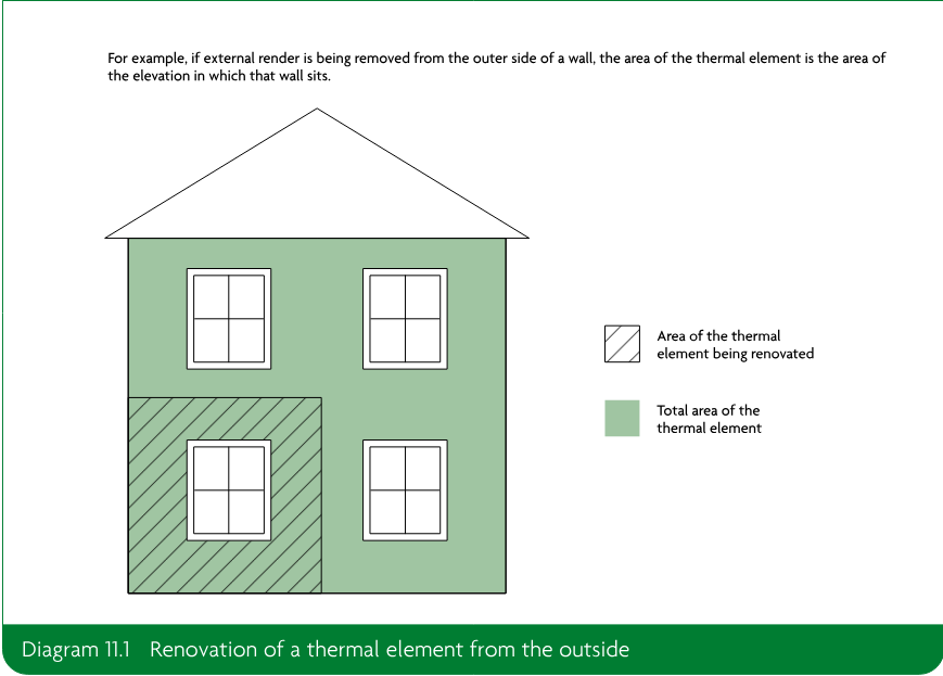
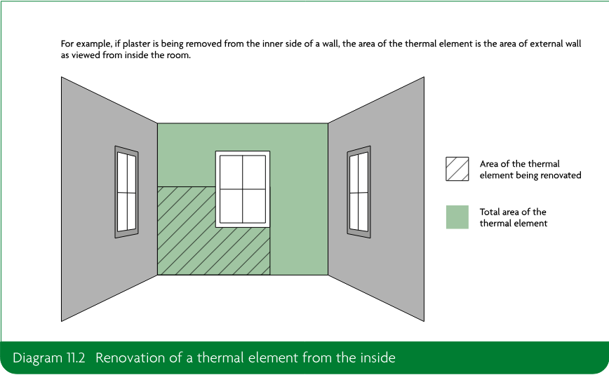
Material change of use and change to energy status
#Source page 89
11.5A material change of use, in relation to buildings other than dwellings, is when a building satisfies any of the following:
a.is used as a hotel or a boarding house, where previously it was not
b.is used as an institution, where previously it was not
c.is used as a public building, where previously it was not
d.is not described in classes 1 to 6 in Schedule 2, where previously it was
e.contains a room for residential purposes, where previously it did not
f.contains at least one room for residential purposes, having previously had a greater or lesser number of rooms for residential purposes
g.is used as a shop where previously it was not.
11.6A change to energy status is when a building was previously exempt from the energy efficiency requirements but now is not. The change to energy status applies to the building as a whole or to parts of the building that have been designed or altered to be used separately. For example, when a previously unheated space becomes part of the heated building.
11.7If there is a material change of use and/or a change to energy status, elements should satisfy all of the following.
a.Existing thermal elements should meet the standards as outlined in paragraphs 4.7 to 4.8.
b.If both of the following apply to existing windows, roof windows, rooflights and doors (controlled fittings), they should be replaced to meet the limiting standards in Table 4.1.
i.They separate a conditioned space from an unconditioned space or the external environment.
ii.They have a U-value higher than either of the following.
•For windows, roof windows and doors – 3.30W/(m²·K).
•For rooflights – 3.80W/(m²·K), calculated by following paragraph 4.4.
In addition, all of the following should be met.
a.New or replaced thermal elements should meet the standards in Table 4.1.
b.New or replaced windows, roof windows, rooflights and doors (controlled fittings) should meet the standards in Table 4.1.
c.The area of openings in the newly created building should not be more than 25% of the total floor area. A larger area of openings may be achieved by following paragraph 11.8.
d.Any fixed building services including building automation and control systems and/or on-site electricity generation that are provided or extended should meet the standards in Sections 5 and 6.
Page 90
#Source page 90
11.8As an alternative to paragraph 11.7, an approved calculation tool may be used to demonstrate that the building primary energy rate and building emission rate from the building after the material change of use would be no greater than if the building had been improved following the guidance in paragraph 11.7.
Regulation 28: Consequential improvements to energy performance
#Source page 91
This section deals with the requirements of regulation 28 of the Building Regulations 2010.
Intention
In the Secretary of State’s view, where regulation 28 applies, the requirements of this regulation are met for existing buildings with a total useful floor area over 1000m² by carrying out consequential improvements that are technically, functionally and economically feasible, by following the guidance in Section 12.
Section 12: Consequential improvements
#Source page 92
12.1For an existing building with a total useful floor area of over 1000m², additional work may be required to improve the overall energy efficiency of the building if proposed work consists of or includes any of the following.
a.An extension.
b.Providing any fixed building service in the building for the first time.
c.Increasing the capacity of any fixed building service (which does not include doing so on account of renewable technology).
Consequential improvements should be carried out to ensure that the entire building complies with Part L of the Building Regulations to the extent that they are technically, functionally and economically feasible.
12.2Where work other than the items listed in paragraph 12.1 is planned as part of the principal works, if they improve the energy performance of the building, these are consequential improvements. Work carried out to compensate for the poorer standard of an extension using the alternative approach to demonstrating compliance described in paragraph 10.11 does not count as a consequential improvement.
Consequential improvements which apply when extending a building
12.3When an existing building with a total useful floor area of over 1000m² is being extended or the habitable area is being increased, consequential improvements should be installed. The measures listed in Appendix D, Table D1, may be considered technically, functionally and economically feasible in normal circumstances.
12.4For an extension or increase in habitable area, the value of the principal works is used to determine the minimum value of the consequential improvement works. The value of the consequential improvement works should not be less than 10% of the value of the principal works.
12.5As part of the initial notice or deposit of plans, a chartered quantity surveyor or other suitably qualified person should produce a signed report that establishes the value of the principal works and the value of the consequential improvements using prices current at the date when the building control body is informed of the proposals.
Consequential improvements on installing or extending the capacity of fixed building services
#Source page 93
12.6If it is proposed to install a fixed building service in an existing building with a total useful floor area of over 1000m², either as a first installation or as an installation that increases the installed capacity of a fixed building service per unit area, then both of the following should be implemented as consequential improvements.
a.Make energy efficiency improvements to the fixed building services to meet the requirements of Part L, where this is practical and technically, functionally and economically feasible.
i.When installing or extending the capacity of fixed building services, the value of the principal works is used to determine the minimum value of the energy efficiency improvements made to fixed building services as consequential improvements. The value of these consequential improvements should not be less than 10% of the value of the principal works, excluding the value of any work to improve other energy efficiency aspects of the building served by the services in meeting paragraph 12.6b.
ii.The measures listed in Appendix D, Table D1, relate to this requirement, and may be considered technically, functionally and economically feasible in normal circumstances.
iii.As part of the initial notice or deposit of plans, a chartered quantity surveyor or other suitably qualified person should produce a signed report that establishes the value of the principal works and the value of the consequential improvements using prices current at the date when the building control body is informed of the proposals.
b.Improve other energy efficiency aspects of those parts of the building served by the fixed building service to meet the requirements of Part L, where this is technically, functionally and economically feasible.
i.All technically, functionally and economically feasible measures to improve the fabric of the building served by the service should be implemented. The extent of the improvements to the fabric should not be determined by the value of the principal works.
ii.The measures in Appendix D, Table D2 relate to this requirement and may be considered technically, functionally and economically feasible in normal circumstances.
Appendix A: Key terms
#Source page 94
Air permeability The measure of airtightness of the building fabric. It is defined as the air leakage rate per hour per m² of envelope area at the test reference pressure differential of 50Pa.
•The limiting air permeability is the worst allowable air permeability.
•The design air permeability is the target value set at the design stage.
•The assessed air permeability is the value used in establishing the building emission rate and the building primary energy rate. The assessed air permeability is based on a measurement of the air permeability of the building concerned.
Airtightness The resistance of the building envelope to infiltration when ventilators are closed. The greater the airtightness at a given pressure difference across the envelope, the lower the infiltration. Building automation and control system.
Building automation and control system A system comprising all products, software and engineering services that can support energy efficient, economical and safe operation of heating, ventilation and air conditioning systems through automatic controls and by facilitating the manual management of those building systems.
Building control body A local authority building control department or an approved inspector.
Building emission rate The building’s CO₂ emission rate expressed as kgCO₂/(m²·year).
Building envelope (in relation to a building) Defined in regulation 35 as the walls, floor, roof, windows, doors, roof windows and rooflights.
Building primary energy rate Expressed as kWh<sub>PE</sub>/(m²·year) and determined using the approved methodology.
Centralised electrically heated A domestic hot water system in which the water is supplied to the draw-off points from a device in which water is heated by an electric element or elements immersed in the stored water. The water heater is situated centrally with a distribution system to supply water to the draw-off points and has a capacity greater than 300 litres.
Centre pane U-value The U-value determined in the central area of the glazing unit, making no allowance for edge spacers or the window frame.
Change to energy status Defined in regulation 2(1) as any change which results in a building becoming a building to which the energy efficiency requirements of these Regulations apply, where previously it was not.
CHPQA quality index An indicator of the energy efficiency and environmental performance of a CHP scheme, certified by the Combined Heat and Power Quality Assurance scheme.
Circuit-watt Refers to the power consumed in lighting circuits by lamps and, where applicable, their associated control gear (including transformers and drivers) and power factor correction equipment.
Coefficient of performance (COP) A measure of the efficiency of a heat pump at specified source and sink temperatures, measured using the procedures in BS EN 14511-2.
•Heating COP = heat output / power input
•% COP (COP × 100) is the heat generator efficiency.
Page 95
#Source page 95
Commissioning When, after all or part of a fixed building service or on-site electricity generation system has been installed, replaced or altered, the system is taken from a state of static completion to working order. Testing and adjusting are carried out for fixed building services, as necessary, to ensure that the whole system uses no more fuel and power than is reasonable in the circumstances. Testing and adjusting are carried out for on-site electricity generation systems, as necessary, to ensure that the whole system produces the maximum amount of electricity that is reasonable in the circumstances.
For each system, commissioning includes all of the following.
•Setting to work.
•Regulation (that is, testing and adjusting repetitively) to achieve the specified performance.
•Calibration.
•Setting up and testing the associated automatic control systems.
•Recording the system settings and the performance test results that have been accepted as satisfactory.
Community heating system A system that supplies heat from a central source within a single building, for example to both dwellings and non-dwellings in a mixed-use building.
Consequential improvements Those energy efficiency improvements required by regulation 28.
Control zone Refers to the independent control of rooms or areas within buildings that need to be heated to different temperatures at different times.
Controlled service or fitting Defined in regulation 2(1) as a service or fitting in relation to which Part G [sanitation, hot water safety and water efficiency], H [drainage and waste disposal], J [combustion appliances and fuel storage systems], L [conservation of fuel and power] or P [electrical safety] of Schedule 1 imposes a requirement.
Direct-fired circulator A domestic hot water system in which the water is supplied to the draw-off points from a hot water vessel in which water is heated by combustion gases from a primary energy source. The unit has no storage volume, as water is stored in a supplementary storage vessel.
Direct-fired continuous flow A domestic hot water system in which the water is supplied to the draw-off points from a device in which cold water is heated by combustion gases from a primary energy source as it flows through the water heater. The water heater is close to the draw-off points. The unit has no storage volume, as water is instantaneously heated as it flows through the device.
Direct-fired storage A domestic hot water system in which the water is supplied to the draw-off points from an integral hot water vessel in which water is heated by combustion gases from a primary energy source.
Display lighting Lighting to highlight displays of exhibits or merchandise, or lighting used in spaces for public leisure and entertainment, such as dance halls, auditoria, conference halls, restaurants and cinemas.
Display window An area of glazing, including glazed doors, to display products or services on offer to the public within a building, positioned as in all of the following.
•At the external perimeter of the building.
•At an access level.
•Immediately adjacent to a pedestrian thoroughfare.
If there is a permanent workspace within one glazing height of the window, this cannot be considered to be a display window. Glazing more than 3m above an access level should not be considered part of a display window, except where either of the following applies.
•The products on display require a greater height of glazing.
Page 96
#Source page 96
•Building work involves changes to the façade and glazing that require planning consent, and planning requirements mean that a greater height of glazing is necessary, e.g. to fit with surrounding buildings or to match the character of the existing façade.
District heat networks Supply heat from a central source to consumers, via a network of underground pipes carrying hot water. Heat networks can cover a large area or even an entire city, or can be relatively local, supplying a small cluster of buildings.
Dwelling A self-contained unit designed to accommodate a single household, including a dwellinghouse and a flat.
Economically feasible The capital cost of a measure will be recouped in energy savings within a reasonable time. For the purposes of this document, economically feasible means that the measure would achieve a simple payback after one of the following.
•7 years, for the installation of thermostatic controls.
•7 years, for the extension of on-site low and zero carbon energy-generating systems which are required as consequential improvements (see Appendix D, Table D1).
•15 years, for any other measure.
Emergency escape lighting The emergency lighting that illuminates an area for the safety of people leaving that area or for people attempting to stop a dangerous process before leaving that area.
Energy efficiency ratio (EER) In chillers, this is calculated by dividing the cooling energy delivered into the cooling system by the energy input to the chiller.
Energy efficiency requirements Defined in regulation 2(1) as the requirements of regulations 23, 25A, 25B, 26, 26A, 26C, 28, 40 and 43 and Part L of Schedule 1.
Energy performance certificate Defined in the Energy Performance of Buildings (England and Wales) Regulation 2012 as a certificate which:
a.in the case of a certificate entered on the register before 9th January 2013 complied with the requirements of regulation 11(1) of the Energy Performance of Buildings (Certificates and Inspections) (England and Wales) Regulations 2007;
b.in the case of a certificate entered on the register on or after 9th January 2013 complies with the requirements of regulation 9(1) of these Regulations; or
c.complies with the requirements of regulation 29 of the Building Regulations 2010.
Envelope area (the measured part of the building) The total area of all floors, walls and ceilings bordering the internal volume that is the subject of a pressure test. This includes walls and floors below external ground level. Overall internal dimensions are used to calculate this envelope area, and no subtractions are made for the area of the junctions of internal walls, floors and ceilings with exterior walls, floors and ceilings.
Existing district heat network A district heat network that is either in operation or is under construction on 15 June 2022. For these purposes, under construction means any of the following.
•The building to house the energy centre has been constructed.
•There is a heat offtake agreement signed between the heat network and a third party.
•Excavation for pipework has been completed.
Fit-out work The work to complete the partitioning and building services within the external fabric of the building (the shell) to meet the specific needs of incoming occupiers. Fit-out work can be carried out either:
•during the same project and time frame as the construction of the building shell
•at a later date, after the shell has been completed.
Fixed building services Defined in regulation 2(1) as any part of, or any controls associated with:
a.fixed internal or external lighting systems (but not including emergency escape lighting or specialist process lighting);
b.fixed systems for heating, hot water, air conditioning or mechanical ventilation; or
Page 97
#Source page 97
c.any combination of systems of the kinds referred to in paragraph (a) or (b).
Fixed external lighting Lighting fixed to an external surface of the building and supplied from the occupier’s electrical system. It excludes lighting in common areas of blocks of flats and in other communal accessways.
g-value A total solar energy transmittance.
Hard water Water which has a high mineral content. For the purposes of this approved document, hard water is water that has a total water hardness of greater than 200ppm of CaCO₃.
Heat generator seasonal efficiency The estimated seasonal heat output from the heat generator divided by the energy input.
Heating appliance or heat generator The part of a heating system that generates useful heat using one or more of the following processes.
•The combustion of fuels in, for example, a boiler.
•The Joule effect, taking place in the heating elements of an electric resistance heating system.
•Capturing heat from ambient air, ventilation exhaust air, or a water or ground heat source using a heat pump.
Heating zone A conditioned area of a building which is on a single floor and has the same thermal characteristics and temperature control requirements throughout.
High excitation purity light sources Colour-tuneable light sources that can be set to at least the colours listed in Table A1 and which have for each of these colours, measured at the dominant wavelength, the minimum excitation purity shown. Intended for use in applications requiring high-quality coloured light.
| Colour | Dominant wavelength (nm) | Minimum excitation of purity (%) |
|---|---|---|
| Blue | 440–490 | 90 |
| Green | 520–570 | 65 |
| Red | 610–670 | 95 |
High-usage entrance door A door to an entrance primarily for people, through which many people are expected to move. Robustness and/or powered operation are the main performance requirements. A high-usage entrance door will have automatic closers and, except where operational requirements preclude it, be protected by a lobby.
Indirect-fired circulator A domestic hot water system in which the water is supplied to the draw-off points from a device in which water is heated by an element through which the heating medium is circulated so as not to mix with the hot water supply. In practice, the heat source is likely to be a boiler dedicated to the supply of domestic hot water.
Installed capacity of a fixed building service per unit area The design output of the distribution system output devices (the terminal units) serving the space in question, divided by the total useful floor area of that space.
Instantaneous electrically heated A domestic hot water system in which the water is supplied to the draw-off points from a device in which cold water is heated by an electric element or elements as it flows through the water heater. The water heater is close to the draw-off points. The unit has no storage volume, as water is instantaneously heated as it flows through the device.
Light source lumens The sum of the average initial (100 hour) lumen output of all the light sources in a luminaire. Does not include any losses or inefficiencies of the luminaire.
Lighting Energy Numeric Indicator (LENI) A measure of the performance of lighting in terms of energy per square metre per year (kWh/m² per year). See Appendix B.
Local electrically heated A domestic hot water system in which the water is supplied to the draw-off points from a device in which water is heated by an electric element or elements immersed in the stored water. The water heater is near the draw-off points and has a storage capacity of between 100 and 300 litres.
Page 98
#Source page 98
Luminaire lumens Equal to (light source lumens × light output ratio) and represents the output of the luminaire. Light output ratio (LOR) is the ratio of the output of the luminaire at stated practical conditions to that of the lamp(s) contained in the luminaire under reference conditions.
**\*Major renovation** Defined in regulation 35 as the renovation of a building where more than 25% of the surface area of the building envelope undergoes renovation.
**\*Material change of use** Defined in regulation 5 as: Where there is a change in the purposes for which or the circumstances in which a building is used, so that after that change:
a.the building is used as a dwelling, where previously it was not;
b.the building contains a flat, where previously it did not;
c.the building is used as an hotel or a boarding house, where previously it was not;
d.the building is used as an institution, where previously it was not;
e.the building is used as a public building, where previously it was not;
f.the building is not a building described in classes 1 to 6 in Schedule 2, where previously it was;
g.the building, which contains at least one dwelling, contains a greater or lesser number of dwellings than it did previously;
h.the building contains a room for residential purposes, where previously it did not;
i.the building, which contains at least one room for residential purposes, contains a greater or lesser number of such rooms than it did previously;
j.the building is used as a shop, where it previously was not; or
k.the building is a building described in regulation 7(4)(a), where previously it was not.
Modulating burner control A type of boiler control that provides a continuously variable firing rate that is altered to match the boiler load over the whole turndown ratio.
Optimum start A control system or algorithm that starts plant operating at the latest time possible to achieve specified conditions at the start of the occupancy period.
Optimum stop A control system or algorithm that stops plant operating at the earliest time possible so that internal conditions will not deteriorate beyond present limits by the end of the occupancy period.
Part load energy efficiency ratio A ratio calculated by dividing the cooling energy delivered into the cooling system by the energy input to the cooling plant. Part load performance for individual chillers is determined assuming that chilled water is provided at 7°C out and 12°C in (at 100% load), under the conditions detailed in Table A2.
| 25% | 50% | 75% | 100% | |
|---|---|---|---|---|
| Percentage part load | ||||
| Air-cooled chiller’s ambient air temperature (°C) | 20 | 25 | 30 | 35 |
| Water-cooled chiller’s entering cooling water temperature (°C) | 18 | 22 | 26 | 30 |
Point-of-use electrically heated A domestic hot water system in which the water is supplied to the draw-off points from a device in which water is heated by an electric element or elements immersed in the stored water. The water heater is close to the draw-off points and has a storage capacity no greater than 100 litres.
Power efficiency The total annual power output of a CHP unit divided by its total annual fuel input.
Primary energy Energy, from renewable and non-renewable sources, that has not undergone any conversion or transformation process.
Page 99
#Source page 99
Principal works The work necessary to achieve the client’s purposes in extending the building and/or increasing the installed capacity of any fixed building services. The value of the principal works is the basis for determining a reasonable provision for some consequential improvements.
Renewable technology Technology that uses renewable resources, which are naturally replenished on a human timescale, to produce electricity. Resources include wind, wave, marine, hydro, biomass and solar.
Rooflight A glazed unit installed out of plane with the surface of the roof on a kerb or upstand. Also sometimes referred to as a skylight.
Roof window A window installed in the same orientation as, and in plane with, the surrounding roof.
**\*Room for residential purposes** Defined in regulation 2(1) as a room, or a suite of rooms, which is not a dwelling-house or a flat and which is used by one or more persons to live and sleep and includes a room in a hostel, an hotel, a boarding house, a hall of residence or a residential home, but does not include a room in a hospital, or other similar establishment, used for patient accommodation.
Seasonal coefficient of performance (SCOP) A measure of the efficiency of a heat pump over the designated heating season, measured using the procedures in BS EN 14825.
Seasonal energy efficiency ratio (SEER) The total amount of cooling energy provided by a single cooling unit over a year, divided by the total energy input to that single cooling unit over the same year.
Sequence control Enables two or more heating boilers to be switched on or off in sequence when the heating load changes.
Simple payback The amount of time it will take to recover the initial investment through energy savings, calculated by dividing the marginal additional cost of implementing an energy efficiency measure by the value of the annual energy savings achieved by that measure, taking no account of VAT. The following guidance should be used.
•The marginal additional cost is the additional cost (materials and labour) of incorporating, for example, additional insulation – not the whole cost of the work.
•The cost of implementing the measure should be based on prices current at the date when the application is made to the building control body and be confirmed in a report signed by a suitably qualified person.
•The annual energy savings should be estimated using the National Calculation Methodology Modelling Guide.
•The energy prices that are current when the application is made to the building control body should be used when evaluating energy savings. Current prices are given on the BEIS website, at: https://www.gov.uk/government/collections/quarterly-energy-prices.
Simplified building energy model One of the current approved procedures for assessing the performance of a building, in line with this document.
Specialist process lighting Lighting to illuminate specialist tasks within a space rather than the space itself. Specialist process lighting includes theatre spotlights, projection equipment, lighting in TV and photographic studios, medical lighting in operating theatres and doctors’ and dentists’ surgeries, illuminated signs, coloured or stroboscopic lighting, and art objects with integral lighting, such as sculptures, decorative fountains and chandeliers.
Standard Assessment Procedure The current approved procedure for assessing the performance of dwellings in line with Approved Document L, Volume 1: Dwellings. The Standard Assessment Procedure is detailed in The Government’s Standard Assessment Procedure for Energy Rating of Dwellings version 10.
Target emission rate The maximum CO₂ emission rate for the building, expressed as kgCO₂/(m²·year).
Target primary energy rate The maximum primary energy use for the building in a year, expressed as kWhₚₑ/(m²·year).
Page 100
#Source page 100
Thermal bridging Occurs when part of a thermal element has significantly higher heat transfer than the materials surrounding it.
**\*Thermal element** Defined in regulation 2(3) and 2(4) as follows.
2(3) In these Regulations “thermal element” means a wall, floor or roof (but does not include windows, doors, roof windows or roof-lights) which separates a thermally conditioned part of the building (“the conditioned space”) from—
a.the external environment (including the ground); or
b.in the case of floors and walls, another part of the building which is—
i.unconditioned;
ii.an extension falling within class 7 of Schedule 2; or
iii.where this paragraph applies, conditioned to a different temperature,
and includes all parts of the element between the surface bounding the conditioned space and the external environment or other part of the building as the case may be.
2(4) Paragraph 2(3)(b)(iii) only applies to a building which is not a dwelling, where the other part of the building is used for a purpose which is not similar or identical to the purpose for which the conditioned space is used.
Thermal envelope The combination of thermal elements of a building that enclose a particular conditioned indoor space or groups of indoor spaces.
Thermal separation Occurs where a building and a conservatory or porch are divided by walls, floors, windows and doors to which one of the following applies.
•The U-values are similar to, or in the case of a newly constructed conservatory or porch do not exceeding, the U-values of the corresponding exposed elements elsewhere in the building.
•In the case of a newly constructed conservatory or porch, windows and doors have similar draught-proofing provisions as the exposed windows and doors elsewhere in the building.
Thermostatic room controls A device or system that automatically controls the output of heating and/or cooling emitters to control the temperature in each room (or, where justified, a heating zone) independently where heating and/or cooling is provided by a fixed building service.
Total useful floor area The total area of all enclosed spaces, measured to the internal face of the external walls. When calculating total useful floor area, both of the following should be taken into account.
•The area of sloping surfaces such as staircases, galleries, raked auditoria and tiered terraces should be taken as their area on plan.
•Areas that are not enclosed, such as open floors, covered ways and balconies, should be excluded.
U-value A measure of the ability of a building element or component to conduct heat from a warmer environment to a cooler environment. It is expressed as the quantity of heat (in watts) that will flow through 1m² of area divided by the difference in temperature (in degrees K) between the internal and external environment. The unit is W/(m²·K).
Weather compensation A system which enables the operating flow temperature of a heating system to be varied. An external sensor communicates with one inside the boiler. The temperature is varied by either of the following.
•Modulating the heat generator output (direct acting).
•Using a mixing valve to adjust the flow temperature to the heat emitters.
Wet heating system When a heating appliance (usually a boiler) produces hot water which is distributed around the building to heat emitters.
Appendix B: Lighting Energy Numeric Indicator (LENI)
#Source page 101
B1The Lighting Energy Numeric Indicator (LENI) method is an alternative approach for complying with the standards for lighting given in Section 6 of this approved document.
B2The LENI should not exceed the lighting energy limit specified in Table B1 for a given illuminance and number of hours run.
Step 1: Determine the lighting energy limit from Table B1.
If display lighting is used, the lighting energy limit may be increased by the value given for normal display lighting for the area of the room where display lighting is used.
Step 2: Calculate the parasitic energy use (Eₚ). If the parasitic energy use is unknown, an allowance of 0.3W/m² should be made for any control system. If no lighting control system is used, then Eₚ = 0.
Step 3: Determine the total power of lighting (Pₗ).
Step 4: Determine the occupancy factor (Fₒ). If no automatic control is used, then Fₒ = 1. If controls turn off the lights within 20 minutes of the room being empty, then Fₒ = 0.8.
Step 5: Determine the factor for daylight (Fᵈ). If no daylight-linked dimming system is used, then Fᵈ = 1. If the electric lighting dims in response to daylight being available, then in areas with adequate daylight Fᵈ = 0.8. This may be taken as all areas within 6m of a window wall or in areas where 10% or more of the roof is translucent or made up of rooflights.
Step 6: Determine the constant illuminance factor (F꜀). Systems that control the lighting in this way have F꜀ = 0.9, and those that do not have F꜀ = 1.
Step 7: Calculate the daytime energy use (Eᵈ).
The daytime energy use is:
Eᵈ(%) = (Pₗ × Fₒ × Fᵈ × F꜀ × Tᵈ) / 1000
Step 8: Calculate the night-time energy use (Eₙ).
The night-time energy use is:
Eₙ(%) = (Pₗ × Fₒ × F꜀ × Tₙ) / 1000
Page 102
#Source page 102
Step 9: Calculate total energy (kWh) per square metre per year (LENI).
The total energy per square metre per year is the sum of the daytime, night-time and parasitic energy uses per year divided by the area (A), as set out in the formula below.
LENI (%) = (Eₚ + Eᵈ + Eₙ) / A
| Hours: Total | Hours: Day | Hours: Night | Illuminance (lux): 50 | Illuminance (lux): 100 | Illuminance (lux): 150 | Illuminance (lux): 200 | Illuminance (lux): 300 | Illuminance (lux): 500 | Illuminance (lux): 750 | Illuminance (lux): 1000 | Display lighting: Normal | Display lighting: Shop window |
|---|---|---|---|---|---|---|---|---|---|---|---|---|
| 1000 | 821 | 179 | 0.69 | 0.68 | 2.57 | 3.00 | 3.96 | 5.93 | 8.83 | 12.59 | 2.50 | |
| 1500 | 1277 | 223 | 1.04 | 0.98 | 3.05 | 3.68 | 5.10 | 8.00 | 12.33 | 17.98 | 3.75 | |
| 2000 | 1726 | 274 | 1.39 | 1.28 | 3.54 | 4.37 | 6.26 | 10.10 | 15.85 | 23.40 | 5.00 | |
| 2500 | 2164 | 336 | 1.73 | 1.60 | 4.04 | 5.07 | 7.43 | 12.23 | 19.41 | 28.85 | 6.25 | |
| 3000 | 2585 | 415 | 2.08 | 1.93 | 4.56 | 5.81 | 8.64 | 14.41 | 23.04 | 34.36 | 7.50 | |
| 3700 | 3133 | 567 | 2.56 | 2.42 | 5.34 | 6.90 | 10.42 | 17.59 | 28.27 | 42.22 | 9.25 | |
| 4400 | 3621 | 779 | 3.05 | 2.97 | 6.20 | 8.08 | 12.33 | 20.95 | 33.73 | 50.27 | 11.00 | 24.20 |
| 5400 | 4184 | 1216 | 3.74 | 3.87 | 7.58 | 9.98 | 15.32 | 26.16 | 42.02 | 62.24 | 13.50 | |
| 6400 | 4547 | 1853 | 4.44 | 4.94 | 9.22 | 12.19 | 18.73 | 31.99 | 51.06 | 74.87 | 16.00 | |
| 8760 | 4380 | 4380 | 6.07 | 8.36 | 14.33 | 18.99 | 28.89 | 48.85 | 76.21 | 108.14 | 21.90 | 48.18 |
Appendix C: Reporting evidence of compliance
#Source page 103
BRUKL report
C1The Building Regulations UK Part L (BRUKL) report should be provided to the building control body and to the building owner to show that building work complies with the energy efficiency requirements.
C2The Simplified Building Energy Model (SBEM) will produce the BRUKL report for the building as a standard output option.
C3Two versions of the BRUKL report should be produced, using the approved software.
a.The first, the design stage BRUKL report, before works begin, to include all of the following.
i.The target primary energy rate and building primary energy rate.
ii.The target emission rate and building emission rate.
iii.A supporting list of specifications.
b.The second, the as-built BRUKL report, to include all of the following.
i.The target primary energy rate and as-built building primary energy rate.
ii.The target emission rate and as-built building emission rate.
iii.A supporting list of specifications and any changes to the list of specifications that was provided at design stage.
The building control body can then use these reports to help check that what was designed has been built. The software includes a facility to compare the design stage and as-built data input files and automatically produces a schedule of changes.
C4The as-built BRUKL report should be signed by the energy assessor to confirm that the as-built calculations are accurate.
C5The as-built BRUKL report must be signed by the client (usually the developer or housebuilder) to confirm that the building has been constructed or completed according to the specifications in the report.
Appendix D: Measures for consequential improvements
#Source page 104
D1For an existing building with a total useful floor area of over 1000m², additional work may be required to improve the overall energy efficiency of the building if proposed work consists of or includes any of the following.
a.An extension.
b.Providing any fixed building service in the building for the first time.
c.Increasing the capacity of any fixed building service (which does not include doing so on account of renewable technology).
D2Additional works to improve energy efficiency as required in these circumstances are known as consequential improvements and are described in detail in Section 12.
Measures usually to be installed whenever consequential improvements are required
D3Energy efficiency improvements to the building are required whenever consequential improvements apply. All technically, functionally and economically feasible measures should be implemented, with the requirement for consequential improvements being met based on the value of the principal works in some circumstances. This is outlined in Section 12.
D4The energy efficiency improvements in Table D1 can be considered technically, functionally and economically feasible in normal circumstances. As such, these measures should usually be installed when consequential improvements are required. These should be installed at least to the extent outlined in Table D1, based on the value of the principal works, as outlined in Section 12.
Additional measures usually to be installed when consequential improvements are required following changes to fixed building service provision
#Source page 105
| Item | Improvement measure |
|---|---|
| 1 | Upgrading heating systems that are more than 15 years old by providing new plant or improved controls. |
| 2 | Upgrading cooling systems that are more than 15 years old by providing new plant or improved controls. |
| 3 | Upgrading air-handling systems that are more than 15 years old by providing new plant or improved controls. |
| 4 | Upgrading general lighting systems that have an average lamp efficacy of less than 60 light source lumens per circuit-watt and that serve areas greater than 100m² by providing new luminaires and/or controls following the guidance in Section 6. |
| 5 | Installing energy metering following the guidance given in CIBSE’s TM39. |
| 6 | Upgrading thermal elements that have U-values higher than those in Table 4.2, column (a), following the guidance in paragraphs 4.7 and 4.8. |
| 7 | Replacing existing windows, roof windows or rooflights (but excluding display windows) or doors (but excluding high-usage entrance doors) that have a U-value higher than the following. a. For windows, roof windows and doors – 3.30W/(m²·K) b. For rooflights – 3.80W/(m²·K), calculated by following paragraph 4.4. |
| 8 | If existing on-site low and zero carbon energy-generating systems provide less than 10% of on-site energy demand: increasing the capacity of on-site systems, provided the increase will achieve a simple payback of 7 years or less. |
| 9 | Measures specified in the recommendations report that accompanies a valid energy performance certificate which will achieve a simple payback of 15 years or less. |
These measures are considered technically, functionally and economically feasible in normal circumstances.
These measures should be installed at least to the extent outlined to meet the reasonable provision criterion, based on the value of the principal works, as outlined in Section 12.
Additional measures usually to be installed when consequential improvements are required following changes to fixed building service provision
D5When consequential improvements apply as a result of providing a fixed building service in the building for the first time or increasing the capacity of an existing fixed building service, additional energy efficiency improvements to those parts of the building served by the service should be made. The extent of these measures should not be based on the value of the principal works, as outlined in Section 12. All technically, functionally and economically feasible measures to improve the parts of the building served by the service to meet the requirements of Part L should be implemented.
D6The measures in Table D2 improve the energy efficiency of those parts of the building served by the service, and can be considered technically, functionally and economically feasible in normal circumstances whenever these additional measures are required.
Page 106
#Source page 106
| Item | Improvement measure |
|---|---|
| 1 | If the installed capacity per unit area of a heating system is increased, both of the following apply. a. Thermal elements within the area served that have U-values higher than those in Table 4.2, column (a), should be replaced or renovated following the guidance in Section 10 or Section 11 of this approved document. b. Existing windows, roof windows or rooflights (but excluding display windows) or doors (but excluding high-usage entrance doors) within the area served should be replaced in line with the guidance in Section 10 if they have U-values higher than: • for windows, roof windows and doors – 3.30W/(m²·K) • for rooflights – 3.80W/(m²·K), calculated by following paragraph 4.4. |
| 2 | If the area-weighted installed capacity of a cooling system will be increased, both of the following apply. a. Thermal elements within heated areas served that have U-values higher than those set out in Table 4.2, column (a), should be replaced or renovated following the guidance in Section 10 or Section 11 of this approved document. b. The solar control provisions should be upgraded if either of the following criteria is met. i. The area of windows and roof windows (but excluding display windows) within the area served exceeds 40% of the façade area. ii. Both: • the area of rooflights exceeds 20% of the area of the roof, and • the design solar load exceeds 25W/m². The upgraded system should meet at least one of the following four criteria. iii. The solar gain per unit floor area averaged over the period 06:30 to 16:30 GMT, and when the building is subject to solar irradiances for July as given in the table of design irradiances in CIBSE’s Guide A, should not be greater than 25W/m². iv. The design solar load should be reduced by at least 20%. v. The effective g-value should be no worse than 0.3. vi. The zone or zones should satisfy the solar gain check in paragraphs 4.16 to 4.18. |
| 3 | Any general lighting system within the area served by the relevant fixed building service that has an average efficacy of less than 60 light source lumens per circuit-watt should be upgraded with new luminaires and/or controls following the guidance in Section 6. |
These measures are considered technically, functionally and economically feasible in normal circumstances.
The extent of these measures should not be based on the value of the principal works, as outlined in Section 12, and should be installed in so far as they are technically, functionally and economically feasible.
Appendix E: Hierarchy for establishing seasonal efficiencies of existing boilers
#Source page 107
E1When a heating system is being replaced in an existing building, paragraph 5.4 should be followed. The seasonal efficiency of the appliance being replaced, if unknown, should be established by following the hierarchy set out below. This is based upon the Non Domestic EPC Conventions for England & Wales Issue 7.1.
1.Use Energy Technology List (ETL) product list part load values at 30% and 100% load.
2.Use current Product Characteristics Database (PCDB) values where available.
3.Use either manufacturer’s information or ‘boiler plate’ information or information from a manufacturer’s technical helpdesk. Where a gross efficiency value is established for a non-condensing boiler then a deduction of 0.05 (i.e. 5%) should be made to convert it to an appropriate seasonal efficiency.
4.Use SAP 10 tables (up to 70kW output).
5.Use suitable SBEM defaults.
Appendix F: Standards referred to
#Source page 108
BS 5422 Method for specifying thermal insulating materials for pipes, tanks, vessels, ductwork and equipment operating within the temperature range -40°C to +700°C [2009]
BS 8850 Fan coil unit performance. Determination of specific fan power. Test method [2020]
BS EN 26 Gas-fired instantaneous water heaters for the production of domestic hot water [2015]
BS EN 89 Gas-fired storage water heaters for the production of domestic hot water [2015]
BS EN 308 Heat exchangers. Test procedures for establishing the performance of air to air and flue gases heat recovery devices [1997]
BS EN 410 Glass in building. Determination of luminous and solar characteristics of glazing [2011]
BS EN 525 Non-domestic direct gas-fired forced convection air heaters for space heating not exceeding a net heat input of 300 kW [2009]
BS EN 621 Non-domestic gas-fired forced convection air heaters for space heating not exceeding a net heat input of 300 kW, without a fan to assist transportation of combustion air and/or combustion products [2009]
BS EN 1020 Non-domestic forced convection gas-fired air heaters for space heating not exceeding a net heat input of 300 kW incorporating a fan to assist transportation of combustion air or combustion products [2009]
BS EN 1507 Ventilation for buildings. Sheet metal air ducts with rectangular section. Requirements for strength and leakage [2006]
BS EN 1886 Ventilation for buildings. Air handling units. Mechanical performance [2007]
BS EN 12237 Ventilation for buildings. Ductwork. Strength and leakage of circular sheet metal ducts [2003]
BS EN 12809 Residential independent boilers fired by solid fuel. Nominal heat output up to 50 kW. Requirements and test methods [2001 + A1: 2004]
BS EN 12831 Energy performance of buildings
BS EN 12831-1 Method for calculation of the design heat load. Space heating load, Module M3-3 [2017]
BS EN 12831-3 Method for calculation of the design heat load – Domestic hot water systems heat load and characterisation of needs, Module M8-2, M8-3. [2017]
BS EN 13403 Ventilation for buildings. Non metallic ducts. Ductwork made from insulation ductboards [2003]
BS EN 13842 Oil fired forced convection air heaters. Stationary and transportable for space heating [2004]
BS EN 14351-1 Windows and doors. Product standard. performance characteristics. Windows and external pedestrian doorsets without resistance to fire and/or smoke leakage characteristics [2006 + AMD 1: 2010]
BS EN 14511-2 Air conditioners, liquid chilling packages and heat pumps for space heating and cooling and process chillers, with electrically driven compressors. Test conditions [2018]
BS EN 14825 Air conditioners, liquid chilling packages and heat pumps, with electrically driven compressors, for space heating and cooling. Testing and rating at part load conditions and calculation of seasonal performance [2018]
BS EN 15232 Energy performance of buildings. Impact of Building Automation, Controls and Building Management [2017]
BS EN 15450 Heating systems in buildings. Design of heat pump heating systems [2007]
Page 109
#Source page 109
BS EN 15502-2-1 Gas-fired central heating boilers. Specific standard for type C appliances and type B2, B3 and B5 appliances of a nominal heat input not exceeding 1 000 kW [2012 + A1: 2016]
BS EN 15502-2-2 Gas-fired central heating boilers. Specific standard for type B1 appliances [2014]
BS EN 16798-3 Energy performance of buildings. Ventilation for buildings. For non-residential buildings. Performance requirements for ventilation and room-conditioning systems [2017]
BS EN ISO 12241 Thermal insulation for building equipment and industrial Installations. Calculation rules [2008]
BS EN ISO 12567 Thermal performance of windows and doors. Determination of thermal transmittance by the hot-box method
BS EN ISO 12567-1 Complete windows and doors [2010]
BS EN ISO 12567-2 Roof windows and other projecting windows [2005]
BS EN ISO 13370 Thermal performance of buildings. Heat transfer via the ground. Calculation methods [2007 incorporating corrigendum March 2009]
BS EN ISO 16484 Building automation and control systems (BACS) [2017 + A1: 2020]
Appendix G: Documents referred to
#Source page 110
Legislation
Ancient Monuments and Archaeological Areas Act 1979, c. 46
Building (Approved Inspectors etc.) Regulations 2010, SI 2010/2215
Building Regulations 2010, SI 2010/2214
Ecodesign Commission Regulation No. 206/2012
Ecodesign Commission Regulation No. 2016/2281
Ecodesign for Energy-Related Products Regulations 2010, SI 2010/2617
Planning (Listed Buildings and Conservation Areas) Act 1990, c. 9
Documents
Building and Engineering Services Association (BESA)
(www.thebesa.com)
DW/143 A Practical Guide to Ductwork Leakage Testing [2013]
DW/144 Specification for Sheet Metal Ductwork [2016]
Building Research Establishment (BRE)
(www.bre.co.uk)
BR 443 Conventions for U-value Calculations [2019]
BR 497 Conventions for Calculating Linear Thermal Transmittance and Temperature Factors. Second Edition [2016]
Digest 498 Selecting Lighting Controls [2014]
Information Paper 1/06 Assessing the Effects of Thermal Bridging at Junctions and Around Openings in the External Elements of Buildings [2006]
National Calculation Methodology (NCM) Modelling Guide (for buildings other than dwellings in England) [2013] Available at www.ncm.bre.co.uk
National Calculation Methodology activity database. Available at www.uk-ncm.org.uk
Simplified Building Energy Model (SBEM) User manual and software. Available at www.ncm.bre.co.uk
Building Services Research and Information Association (BSRIA)
#Source page 111
(www.bsria.com)
BG 26/2011 Building Manuals and Building User Guides – Guidance and worked examples [2011]
BSRIA Commissioning Guides as follows:
•BG 2/2010 Commissioning Water Systems [2010]
•BG 29/2021 Pre-Commission Cleaning of Pipework Systems. Sixth Edition [2021]
•BG 49/2015 Commissioning Air Systems [2015]
Chartered Institution of Building Services Engineers (CIBSE)
(www.cibse.org)
CIBSE Commissioning Codes as follows:
•Commissioning Code A Air Distribution Systems [2006]
•Commissioning Code B Boilers [2002]
•Commissioning Code C Automatic Controls [2001]
•Commissioning Code L Lighting [2018]
•Commissioning Code M Management [2003]
•Commissioning Code R Refrigeration [2002]
•Commissioning Code W Water Distribution Systems [2010]
Guide A Environmental Design [2015]
Guide B1 Heating [2016]
Society of Light and Lighting (SLL) Lighting Handbook [2018]
TM23 Testing Buildings for Air Leakage [2022]
TM31 Building Log Book Toolkit [2006]
TM39 Building Energy Metering [2009]
TM54 Evaluating Operational Energy Use at the Design Stage [2022]
Department for Business, Energy and Industrial Strategy (BEIS)
(www.gov.uk/beis)
The Government’s Standard Assessment Procedure for Energy Rating of Dwellings, SAP 10. Available at www.bregroup.com/sap/sap10/
Current Energy Prices. Available at www.gov.uk/government/organisations/department-of-energy-climate-change/about/statistics#energy-price-statistics
Energy Technology List. Available at www.gov.uk/guidance/energy-technology-list
Department for Levelling-Up, Housing and Communities
(www.gov.uk/dluhc)
Approved software for the production of non-domestic Energy Performance Certificates (www.gov.uk/government/publications/department-for-communities-and-local-government-approved-software-for-the-production-of-non-domestic-energy-performance-certificates-epc)
National Calculation Methodology Modelling Guide (for buildings other than dwellings in England) [2021]. Available at: https://www.uk-ncm.org.uk/
Glass and Glazing Federation (GGF)
(ggf.org.uk)
Glazing Manual Data Sheet 2.3, Guide to the Calculation of Energy Ratings for Windows, Roof Windows and Doors [2016]
Historic England
(historicengland.org.uk)
Energy Efficiency in Historic Buildings: Application of Part L of the Building Regulations to Historic and Traditionally Constructed Buildings [2017]
Ministry of Housing, Communities and Local Government (MHCLG)
Manual to the Building Regulations: A Code of Practice for Use in England [2020]
National Association of Rooflight Manufacturers (NARM)
#Source page 112
(www.narm.org.uk)
Technical Document NTD02 Assessment of Thermal Performance of Out-of-plane rooflights [2010]
Non-Domestic Energy Performance Certificate (NDEPC) Conventions Group
Non Domestic EPC Conventions for England & Wales Issue 7.1.
Thermal Insulation Manufacturers and Suppliers Association (TIMSA)
(timsa.org.uk)
HVAC Guidance for Achieving Compliance with Part L of the Building Regulations [2006]
Page 113
#Source page 113
Page 114
#Source page 114
List of Approved Documents
#Source page 115
The following documents have been published to give guidance on how to meet the Building Regulations. You can find the date of the edition approved by the Secretary of State at www.gov.uk.
Approved Document A Structure
Approved Document B Fire safety Volume 1: Dwellings
Approved Document B Fire safety Volume 2: Buildings other than dwellings
Approved Document C Site preparation and resistance to contaminants and moisture
Approved Document D Toxic substances
Approved Document E Resistance to the passage of sound
Approved Document F Ventilation Volume 1: Dwellings
Approved Document F Ventilation Volume 2: Buildings other than dwellings
Approved Document G Sanitation, hot water safety and water efficiency
Approved Document H Drainage and waste disposal
Approved Document J Combustion appliances and fuel storage systems
Approved Document K Protection from falling, collision and impact
Approved Document L Conservation of fuel and power Volume 1: Dwellings
Approved Document L Conservation of fuel and power Volume 2: Buildings other than dwellings
Approved Document M Access to and use of buildings Volume 1: Dwellings
Approved Document M Access to and use of buildings Volume 2: Buildings other than dwellings
Approved Document O Overheating
Approved Document P Electrical safety – Dwellings
Approved Document Q Security – Dwellings
Approved Document R Infrastructure for electronic communications Volume 1: Physical infrastructure and network connection for new dwellings
Approved Document R Infrastructure for electronic communications Volume 2: Physical infrastructure for high-speed electronic communications networks
Approved Document S Infrastructure for the charging of electric vehicles
Approved Document 7 Materials and workmanship
Page 116
#Source page 116
The Building Regulations 2010, Approved Documents are available from:
RIBA Books
Online: www.architecture.com/ribabooks Telephone: +44 (0)20 7496 8383 Email: sales@ribabookshops.com
ISBN 978 1 914124 79 2
© Crown Copyright 2021 The content of this publication, excluding logos, may be reproduced free of charge in any format or medium for research, private study or for internal circulation within an organisation. This is subject to it being reproduced accurately and not used in a misleading context. The material must be acknowledged as Crown copyright and the title and edition of the publication specified. This document/publication is value added. You may re-use the content (not including logos) free of charge in any format or medium, under the terms of the Open Government Licence. To view this licence, visit: http://www.nationalarchives.gov.uk/doc/open-government-licence/ or write to the Information Policy Team, The National Archives, Kew, London TW9 4DU, or e-mail: psi@nationalarchives.gov.uk.
If you require this publication in an alternative format, please email: alternativeformats@communities.gov.uk. Copyright in the typographical arrangement, excluding logos, of the cover and internal page layouts of this publication rests with the Publisher.