Northern Ireland Technical booklet C
Technical booklet C - Site preparation and resistance to moisture - October 2012
Library captured 10 September 2026 · Source updated 25 August 2026
● Finance and ● Personnel
#Source page 1
Department of
● Finance and ● Personnel
G u i d a n c e
Te c h n i c a l B o o k l e t
C
Sit e prep aration an d resista nce to cont amin an t s and m oi stu re
October 2012
Page 2
#Source page 2
Contents page Introduction 3
Part C Regulations 6
Guidance Performance and introduction to provisions 8
Buildings of historic or architectural merit 11
Section 3 Resistance to contaminants 14
Naturally occurring contaminants Radon 14
Manmade contaminants 17
Resistance to moisture from the ground 20
Page 3
#Source page 3
Section 7 Roofs
Technical Booklets
#Source page 4
Introduction
Technical Booklets
This Technical Booklet, which takes effect on 31st October 2012, is one of a series that has been prepared by the Department of Finance and Personnel (the Department) for the purpose of providing practical guidance with respect to the technical requirements of the Building Regulations (Northern Ireland) 2012 (the Building Regulations).
At the back of each Technical Booklet is a list of all the Technical Booklets that have been prepared and published by the Department for this purpose.
The guidance given in a Technical Booklet includes performance standards and design provisions relating to compliance with specific aspects of the Building Regulations for the more common building situations.
If the guidance in a Technical Booklet is followed there will be a presumption of compliance with the requirements of those Building Regulations covered by that guidance. However, this presumption can be overturned, so simply following the guidance does not guarantee compliance. For example, if a particular circumstance is not one of the more common building situations the design provisions given in the Technical Booklet may not be appropriate.
There are likely to be alternative ways of demonstrating compliance with the relevant requirements of the Building Regulations other than by following a design provision given in a Technical Booklet. There is therefore no obligation to adopt any particular provision set out in a Technical Booklet, should you decide to comply in some other way. However, you will have to demonstrate that your alternative solution meets the relevant requirements of the Building Regulations by those other means.
This Technical Booklet
Requirements
The guidance contained in this Technical Booklet relates only to the requirements of regulations 26, 27, 28 and 29. The work will also have to comply with all other relevant requirements of the Building Regulations.
Materials and workmanship
Any building work which is subject to requirements imposed by Part A of the Building Regulations should be carried out in accordance with regulation 23 of those regulations. Guidance on meeting these requirements for materials and workmanship is given in Technical Booklet B which supports Part B.
The Building Regulations are made for specific purposes, primarily securing the health, safety, welfare and convenience of people and for the conservation of fuel and power. Standards and technical approvals are relevant guidance to the extent that they relate to these purposes. However, they may also address other aspects of performance such as serviceability, or aspects which although they relate to health and safety are not covered by the Building Regulations.
Named standards
#Source page 5
Where this Technical Booklet makes reference to a named standard, the relevant version of the standard is the one listed in the Appendix. However, if this version has been replaced or updated by the issuing standards body, the new version may be used as a source of guidance provided that it continues to address the relevant requirements of the Building Regulations.
Diagrams
The diagrams in this Technical Booklet supplement the text. They do not show all the details of construction and are not intended to illustrate compliance with any other requirement of the Building Regulations. They are not necessarily to scale and should not be used as working details.
Protected buildings
District councils have a duty to take account of the desirability to preserve the character of protected buildings when carrying out their functions under Building Regulations. Therefore, where work is to be carried out to a protected building to comply with Part C or any other Part of the Building Regulations, special consideration may be given to the extent of such work for compliance where it would unacceptably alter the character or appearance of the building. Protected buildings are defined in Article 3A(2) of the Building Regulations (Northern Ireland) Order 1979 (as amended).
Other legislation
The provisions of this Technical Booklet relate to the requirements of Building Regulations and do not include measures which may be necessary to meet the requirements of other legislation. Such other legislation may operate during the design or construction stages or when a building is brought into use and can extend to cover aspects which are outside the scope of the Building Regulations.
The Workplace (Health, Safety and Welfare) Regulations (Northern Ireland) 1993
The Workplace (Health, Safety and Welfare) Regulations (Northern Ireland) 1993 (the Workplace Regulations) contain some requirements which affect building design. The main requirements are now covered by the Building Regulations, but for further information see – The Workplace Regulations and the Workplace Health, Safety and Welfare Approved Code of Practice.
The Workplace Regulations apply to the common parts of flats and similar buildings if people such as cleaners, wardens and caretakers are employed to work in these common parts. Where the requirements of the Building Regulations that are covered by Part C do not apply to dwellings, the provisions may still be required in the situations described above in order to satisfy the Workplace Regulations.
Waste and Contaminated Land (Northern Ireland) Order 1997
#Source page 6
This Order sets out the regime for identifying and remediating contaminated land and within the context of ‘proposed development’ this regime is normally applied when contaminated land is identified at the planning stage. The planning authority in Northern Ireland operates in conjunction with DOE Northern Ireland Environment Agency (Contaminated Land Section) to apply a condition on the planning decision requiring a remediation strategy to be submitted by a suitably qualified person and for the strategy to be implemented and verified before development is permitted to commence.
Planning (Northern Ireland) Order 1991
Development in areas of flood risk is regulated by the Northern Ireland Planning Service under the Planning (Northern Ireland) Order 1991. The planning policy in relation to flood risk is set out in Planning Policy Statement 15 “Planning and Flood Risk” (PPS 15). The main objectives of the policy include adopting a precautionary approach when determining planning applications and ensuring that new development is not exposed to the direct threat of flooding.
Flood risk
The susceptibility of land to flooding is a material consideration which is taken into account by the Northern Ireland Planning Service in determining planning applications. There is a presumption in planning guidance that development should not take place in areas that are susceptible to flooding (see DOE NI PPS 15 Planning and Flood Risk).
The Building Regulations do not set any requirements for resistance to flooding. However, where planning permission is granted for a building in an area considered to be at risk of flooding, or where a building in a flood risk area is being renovated it can be constructed with mitigating measures. For example –
(a)elevated ground water levels or flow of subsoil water across the site can be alleviated by the provision of adequate subsoil drainage (see Section 4);
(b)sewer flooding due to backflow or surcharging of sewers or drains can be addressed through the use of nonreturn valves and antiflooding devices (see paragraphs 4.6 and 4.7);
(c)resistance to moisture from the ground can be addressed through the use of water resistant construction (see Sections 5 and 6).
Further information on flood resilient and resistant construction can be found in the following publications –
CLG publication Improving the flood performance of new buildings: flood resilient construction;
CLG publication Preparing for floods: interim guidance for improving the flood resistance of domestic and small business properties; and
Scottish Office publication Design guidance on flood damage to dwellings.
See also the Construction Industry Research and Information
Association (CIRIA) website which has links to current information.
PART C
#Source page 7
Part C Regulations
Part C (comprising regulations 25 – 29) of the Building Regulations which sets out the requirements for site preparation and resistance to contaminants and moisture, has been replicated below for the convenience of the user of this Technical Booklet and is taken directly from the Building Regulations (Northern Ireland) 2012.
Any person who intends to demonstrate compliance with the Building Regulations by following the guidance given in this Technical Booklet is advised to ensure that the regulations below are current on the date when plans are deposited or notices given to the district council.
As Part A (comprising regulations 1 – 21) of the Building Regulations sets out the interpretation along with the procedural requirements relating to the application of the regulations, the Department advises that all Parts of the Building Regulations be read in conjunction with Part A of those regulations.
The Building Regulations (Northern Ireland) 2012 and any subsequent amendment may be viewed by following the links from the Department’s website at “www.buildingregulationsni.gov.uk”.
PART C
Site preparation and resistance to contaminants and moisture
Application and interpretation
25.—(1) Regulation 28 in respect of resistance to ground moisture of floors and walls, and weather resistance of walls, shall not apply where the building is intended to be used wholly for—
(a)storing goods, provided that any person who is habitually employed in the building is engaged only in storing, caring for or removing the goods; or
(b)a purpose such that compliance with regulation 28 would not serve to increase protection to the health or safety of any person habitually employed in the building.
(2)Regulation 29 applies only to a dwelling.
(3)In this Part—
“Contaminant” includes any substance which is or could become corrosive, explosive, inflammable, radioactive or toxic and includes deposits of faecal or animal matter;
“Floor” includes any base or structure between the surface of the ground, or the surface of any hardcore laid upon the ground, and the upper surface of the floor;
“Moisture” includes water in liquid, solid, semisolid or gaseous form but not flood water;
“Radon affected area” means any area designated as such by the Health Protection Agency in the publication ‘Radon in Dwellings in Northern Ireland: 2009 Review and Atlas’; and
“Wall” means any opaque part of the external envelope of a building that is at an angle of 70º or more to the horizontal and includes piers, chimneys, columns and parapets which form part of the wall.
Site preparation and resistance to contaminants
#Source page 8
26.—(1) The site of a building and the ground adjacent to it shall be prepared and treated, and measures shall be taken, so as to prevent, as far as reasonably practicable, any harmful effect on the building or the health or safety of the occupants caused by—
(a)vegetable soil; and
(b)contaminants.
(2) Without prejudice to the generality of paragraph (1) measures shall be taken to prevent or limit the ingress of radon from the ground into any dwelling situated in a radon affected area.
Subsoil drainage
27.The site of a building and the ground adjacent to it shall be drained as far as reasonably practicable, or the building otherwise protected so as to prevent any harmful effect on the building or the health of the occupants caused by—
(a)ground water; and
(b)existing subsoil drainage.
Resistance to moisture and weather
28.Every wall, floor and roof shall be constructed so as to prevent any harmful effect on the building or the health of the occupants caused by the passage of moisture to any part of the building from—
(a)the ground; and
(b)the weather.
Condensation
29.A building to which this regulation applies shall be designed and constructed so as to prevent, as far as reasonably practicable, any harmful effect on the building from moisture in the form of interstitial condensation.
Relevant definitions in regulation 2 in Part A of the Building Regulations.
“Drain” “Dwelling” “Site”
Site preparation and resistance to contaminants
#Source page 9
Guidance Performance and introduction to provisions
Site preparation and resistance to contaminants
Performance
0.1It is the view of the Department that the requirements of regulation 26(1) will be met by making reasonable provisions to prevent harmful effects on the building and to secure the health and safety of persons in and about the building against adverse effects of –
(a)unsuitable material including vegetable soil; and
(b)contaminants on the site and the ground adjacent to the building.
0.2It is the view of the Department that the requirements of regulation 26(2) will be met if dwellings in radon affected areas adequately limit the ingress of radon from the ground.
Introduction to provisions in Sections 2 and 3
0.3The guidance in Section 2 is to ensure that the site is prepared and treated to prevent harmful effect on the building and on the health and safety of the occupants by requiring an appropriate site investigation to be carried out and the findings used to determine the extent of site preparation work needed.
Vegetable matter and other unsuitable materials should be removed from the ground to be covered by the building.
0.4The guidance in Section 3 is to ensure that where a dwelling is located in the radon risk category of 13% or any category above this risk on the radon map in ‘Radon in Dwellings in Northern Ireland: 2009 Review and Atlas’ then radon protection will be required.
Where manmade contaminants have not been identified in the normal way at planning stage, but are discovered during the building process, then in this exceptional circumstance the district council will require the site to be remediated.
Subsoil drainage
Performance
0.5It is the view of the Department that the requirements of regulation 27 will be met if the site of the building and the ground adjacent to it is drained by subsoil drainage as far as reasonably practicable, or the building is otherwise protected to prevent any harmful effect on the building or the health and safety of the occupants caused by the occurrence of ground water or any preexisting subsoil drainage.
Introduction to provisions in Section 4 of this Technical Booklet
#Source page 10
0.6The guidance in Section 4 is to prevent harmful effect on the building and the health of occupants by any existing active subsoil drainage which is disturbed by the development and then requiring the subsoil drainage to be relaid, rerouted or redirected.
Where there is a risk of ground water occurring beneath the building or around the building due to a rise in the water table or otherwise then subsoil drainage (or other effective means of safeguarding) should be provided.
Where water borne contaminants become evident as a result of excavations and are transported to the foundations or into the building or its services then remedial subsoil drainage should be provided.
Resistance to moisture and weather
Performance
0.7It is the view of the Department that the requirements of regulation 28 will be met if the floors, walls and roofs are constructed to protect the building and secure the health and safety of persons in the building from harmful effects caused by the passage of moisture from the ground and the weather.
Introduction to provisions in Sections 5, 6 and 7
0.8Section 5 contains guidance on the construction of floor types which will resist the passage of moisture from the ground.
Section 6 contains guidance on the construction of wall types which will resist the passage of moisture from the ground and also from the weather.
Section 7 contains guidance on the construction of roof types which will resist the passage of moisture from the weather.
Condensation
Performance
0.9It is the view of the Department that the requirements of regulation 29 will be met if the floors, walls and roofs of a dwelling are designed and constructed to protect the dwelling from harmful effects caused by interstitial condensation.
Introduction to provisions in Section 8
0.10The guidance in Section 8 is to ensure that interstitial condensation in a dwelling is avoided by following the design and construction guidance given in the specified BS and BRE technical documents.
Definitions
#Source page 11
Section 1 General
Definitions
1.1In this Technical Booklet the following definitions apply –
Contaminant – is defined in regulation 25 in Part C of the Building Regulations. Drain – is defined in regulation 2 in Part A of the Building Regulations. Dwelling – is defined in regulation 2 in Part A of the Building Regulations. Floor – is defined in regulation 25 in Part C of the Building Regulations. Ground water – water in liquid form, either as a static water table or flowing through the ground.
Interstitial condensation – conversion of water vapour to liquid water which occurs within or between the layers of a construction. Moisture – is defined in regulation 25 in Part C of the Building Regulations. Precipitation – moisture in liquid, solid or semisolid form falling from the atmosphere, usually as rain, sleet, snow or hail. In this Technical Booklet, the term ‘precipitation’ includes spray blown from the sea or any other body of water adjacent to the building.
Radon affected area – is defined in regulation 25 in Part C of the Building
Regulations. Roof – any part of the external envelope of a building that is at an angle of less than 70° to the horizontal.
Site – in relation to a building, means the area of ground covered or to be covered by the building, including its foundations and the ground adjacent to it.
Spray – water droplets driven by the wind from the surface of the sea or other bodies of water adjacent to buildings. (Sea spray can be especially hazardous to materials because of its salt content).
Vapour control layer – a layer intended to limit the transport of water vapour through the building fabric by diffusion or by air movement. Wall – is defined in regulation 25 in Part C of the Building Regulations.
Buildings of historic or architectural merit
#Source page 12
1.2Special considerations may apply where the building to which the work is to be carried out has historic or architectural merit and compliance with Part C of the Building Regulations would unacceptably alter the character or appearance of the building.
1.3When undertaking work to or in connection with a building of historic or architectural merit, the aim should be to follow the guidance in this Technical Booklet to the extent that it is practicable. Particular issues in relation to work to buildings that warrant sympathetic treatment and where specialist advice from conservation experts would be beneficial include –
(a)restoring the historic character of a building that has been subject to inappropriate alteration (e.g. replacement windows, doors and rooflights);
(b)rebuilding a building (e.g. following a fire or filling in a gap site in an historic terrace); and
(c)making provisions for the fabric of historic buildings to “breathe” to control moisture and long term decay problems.
Site investigation
#Source page 13
Section 2 Site preparation
Site investigation
2.1The nature and extent of site preparation will depend on the findings of the site investigation. The site investigation (relevant to Sections 2, 3 and 4 of this Technical Booklet) should consist of a number of well defined stages –
(a)Planning the investigation. Clear objectives should be set for the investigation, including the scope and requirements, which enable the investigation to be planned and carried out efficiently and provide the required information;
(b)Desk study. A review of the historical, geological and environmental information about the site is essential;
(c)Site reconnaissance or walk over survey. This stage of the investigation facilitates the identification of actual and potential physical hazards and the design of the main investigation; and
(d)Main investigation and reporting. This will usually include intrusive and nonintrusive sampling and testing to provide soil parameters for design and construction. The main investigation should be preceded by (b) and (c) above.
2.2The extent and level of investigation needs to be tailored to the type of development and the previous use of land. Typically the site investigation should include susceptibility to ground water levels and flow, underlying geology, and ground and hydrogeological properties. A geotechnical site investigation should identify physical hazards for site development, determine an appropriate design, and provide soil parameters for design and construction. BS 5930 provides comprehensive guidance on site investigations. Guidance on site investigation for lowrise building is also available in the following BRE Digests –
Digest 318 Site investigation for lowrise building: desk studies;
Digest 322 Site investigation for lowrise building: procurement;
Digest 348 Site investigation for lowrise building: the walkover survey;
Digest 381 Site investigation for lowrise building: trial pits;
Digest 383 Site investigation for lowrise building: soil description; and
Digest 411 Site investigation for lowrise building: direct investigations.
Reference should also be made to BS 81031 Structural design of low rise buildings.
2.3Where the site is potentially affected by contaminants, a combined geotechnical and geoenvironmental investigation should be considered. Guidance on sites affected by contaminants is given in Section 3.
2.4Where a site investigation report has been produced, a copy of the report should be given to the district council to facilitate the assessment of the submission.
Unsuitable material
#Source page 14
2.5Vegetable matter such as turf and roots should be removed from the ground to be covered by the building at least to a depth to prevent later growth. The harmful effect that vegetation roots may have on the building should be assessed.
2.6On sites previously used for buildings, consideration should be given to the presence of existing foundations, services, buried tanks and any other infrastructure that could endanger persons in and about the building and any land associated with the building.
2.7Where the site contains fill or made ground, consideration should be given to its compressibility and its potential for collapse on wetting, and to appropriate remedial measures to prevent damaging differential settlement. Guidance is given in BRE Digest 427 Lowrise buildings on fill and BRE Report BR 424 Building fill: Geotechnical aspects.
Introduction
#Source page 15
Section 3 Resistance to contaminants
Introduction
3.1A wide range of solid, liquid and gaseous manmade contaminants can arise on sites, especially those that have had a previous industrial or commercial use. Other sites, with a generally rural use such as agriculture or forestry may be contaminated by pesticides, fertiliser, fuels, oils and decaying matter of biological origin.
3.2Contamination of a site will normally be identified as part of the planning process. Where contamination of a site is identified, planning permission will only be granted subject to the condition that the contamination is remediated such that the site is restored to a state suitable for the proposed development.
3.3The application of regulation 26(1) is based on the presumption that the area of the land within the boundary of the site will be free from contaminants. It may be that the site was not contaminated or any identified contamination was remediated prior to commencement of construction of the building.
3.4The only active use of the district council's power to deal with contaminants is in relation to the risk of radon ingress in dwellings where dwellings in a designated radon affected area are required to have measures incorporated to resist the ingress of radon.
Where, in exceptional circumstances, contamination of a site is only discovered during the building process, regulation 26(1)(b) empowers the district council to require the site to be remediated to a state suitable for the proposed development.
3.5Useful information/guidance on manmade contaminants is given in paragraphs 3.13 – 3.16 in relation to whether or not a site may be contaminated due to its former usage.
Naturally occurring contaminants Radon
General
3.6Radon is a naturally occurring radioactive colourless and odourless gas which is formed in small quantities by radioactive decay wherever uranium and radium are found. It can move through the subsoil and so into buildings. Some parts of Northern Ireland have higher levels than elsewhere. Exposure to high levels of radon for long periods increases the risk of developing lung cancer.
It is not possible to predict the radon concentration in a dwelling to be built on a particular site prior to construction.
Radon affected areas
#Source page 16
3.7Maps showing the probability of radon concentrations in dwellings in Northern Ireland are available in the Health Protection Agency report Radon in Dwellings in Northern Ireland: 2009 Review and Atlas.
This document is available as a free download from the Northern Ireland Environment Agency’s (NIEA) website http://www.nienvironment.gov.uk.
3.8The areas on the maps with a greater than 1% probability of the radon level in a dwelling exceeding the current UK Action Level are designated radon affected areas. The Action Level is the maximum annual average radon concentration in dwellings that is set by the Health Protection Agency. Radon concentration is measured in becquerels per cubic metre (Bq/m3) and the Action Level is currently set at 200 Bq/m3.
3.9The areas where radon protection is required may be reviewed by the Department in the light of further advice from the NIEA.
Radon protection in dwellings
3.10In radon affected areas –
(a)new dwellings;
(b)alterations, extensions, conservatory and porch extensions (including exempt conservatory and porch extensions) to dwellings; and
(c)buildings converted to dwellings through a material change of use,
should be protected from the ingress of radon in accordance with paragraphs 3.11 and 3.12.
3.11Guidance on protective measures is given in the following publications produced by BRE –
(a) BR 413 Radon: guidance on protective measures for new dwellings in
Northern Ireland. Note: the following matters in BR 413 no longer apply –
(i)the radon survey (on which the maps are based) referred to on page 3 has been superseded – for the new survey see paragraph 3.7 of this Technical Booklet;
(ii)the radon maps at the back of the publication – for the new maps see paragraph 3.7 of this Technical Booklet;
(iii) the light and dark grey shading on the maps – the new maps show 5 levels of radon risk in shades of yellow to brown; three shades cover the risk level from 1% to 10%, and two shades cover over 10%; and
(iv) 5 km grid squares – the new maps show 1 km grid squares.
(b)GBG 73 Radon protection for new domestic extensions and conservatories with solid concrete ground floors; and
Page 17
#Source page 17
(c)BR 267 Major alterations and conversions: a BRE guide to radon remedial measures in existing dwellings.
GBG 73 and BR 267 are written for England & Wales. The references to radon maps and the Building Regulations do not apply in Northern Ireland; however, the guidance in these documents is equally relevant to Northern Ireland.
3.12The level of protection required in Northern Ireland is given in Table 3.1.
Table 3.1 Radon protection required
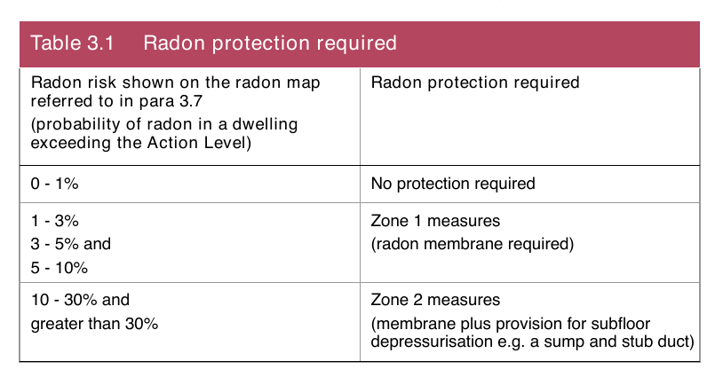
| Radon risk shown on the radon map referred to in para 3.7 (probability of radon in a dwelling exceeding the Action Level) | Radon protection required |
| 0 1% | No protection required |
| 1 3% 3 5% and 5 10% | Zone 1 measures (radon membrane required) |
| 10 30% and greater than 30% | Zone 2 measures (membrane plus provision for subfloor depressurisation e.g. a sump and stub duct) |
Manmade contaminants
#Source page 18
3.13Manmade contamination, or the potential for it, is a material planning consideration which is taken into account by the Northern Ireland Planning Service in determining planning applications. Where planning permission is granted for a development it may be granted subject to conditions or with informatives designed to minimise risk associated with the suspected contaminants to future users or occupiers of the site. The responsibility for assessing whether or not land is contaminated rests with the developer and expert advice should be sought where necessary. Examples of sites likely to contain contaminants are given in Table 3.2.
Table 3.2 Examples of sites likely to contain contaminants
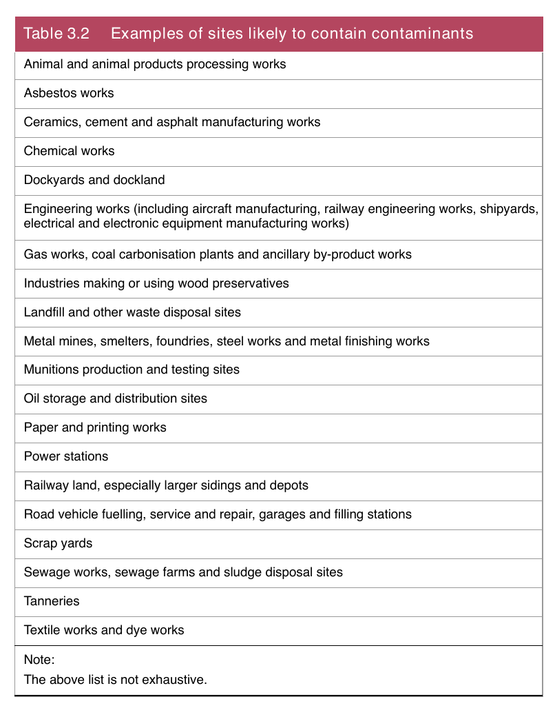
Animal and animal products processing works
Asbestos works
Ceramics, cement and asphalt manufacturing works
Chemical works
Dockyards and dockland
Engineering works (including aircraft manufacturing, railway engineering works, shipyards, electrical and electronic equipment manufacturing works)
Gas works, coal carbonisation plants and ancillary byproduct works
Industries making or using wood preservatives
Landfill and other waste disposal sites
Metal mines, smelters, foundries, steel works and metal finishing works
Munitions production and testing sites
Oil storage and distribution sites
Paper and printing works
Power stations
Railway land, especially larger sidings and depots
Road vehicle fuelling, service and repair, garages and filling stations
Scrap yards
Sewage works, sewage farms and sludge disposal sites
Tanneries
Textile works and dye works
Note: The above list is not exhaustive.
Page 19
#Source page 19
3.14There may be some occasions when a site containing contaminants has not been identified at planning stage, and the presence of contaminants is suspected later. Some signs indicating the possible presence of contaminants are given in Table 3.3.
Table 3.3 Examples of possible contaminants
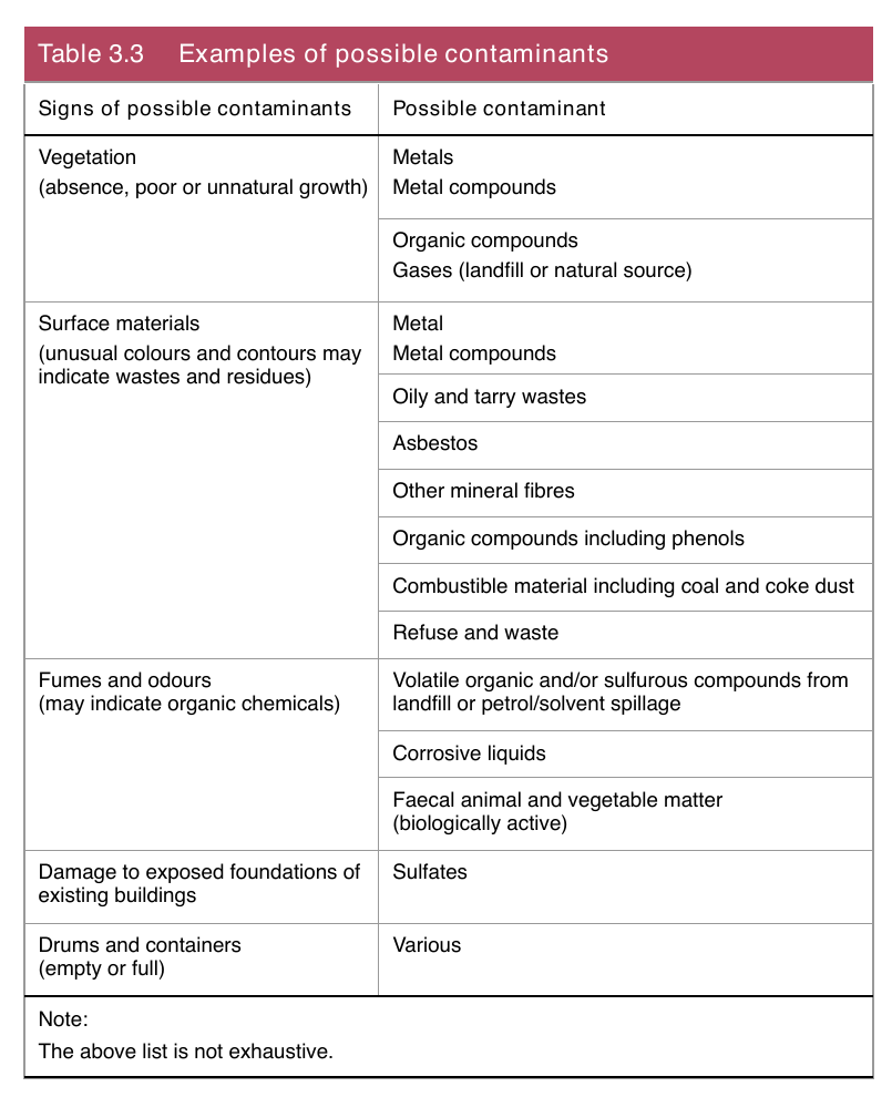
| Signs of possible contaminants | Possible contaminant |
|---|---|
| Vegetation (absence, poor or unnatural growth) | Metals Metal compounds |
| Organic compounds Gases (landfill or natural source) | |
| Surface materials (unusual colours and contours may indicate wastes and residues) | Metal Metal compounds |
| Oily and tarry wastes | |
| Asbestos | |
| Other mineral fibres | |
| Organic compounds including phenols | |
| Combustible material including coal and coke dust | |
| Refuse and waste | |
| Fumes and odours (may indicate organic chemicals) | Volatile organic and/or sulfurous compounds from landfill or petrol/solvent spillage |
| Corrosive liquids | |
| Faecal animal and vegetable matter (biologically active) | |
| Damage to exposed foundations of existing buildings | Sulfates |
| Drums and containers (empty or full) | Various |
| Note: The above list is not exhaustive. |
3.15If signs of possible contaminants are identified the district council and the Northern Ireland Environment Agency should be informed at once. If the presence of contaminants is confirmed some form of remediation may be required and where necessary expert advice should be sought to provide a remedial solution.
3.16Where contamination of a site is discovered during the building process, regulation 26(1)(b) empowers the district council to require the site to be remediated to a state suitable for the proposed development.
Subsoil drainage
#Source page 20
Section 4 Subsoil drainage
Subsoil drainage
4.1The provisions that follow assume that the site of the building and the ground adjacent to it is not subject to flooding.
4.2Where the water table can rise to within 250 mm of the lowest damp proof membrane (DPM) of the building, or where surface water could enter or adversely affect the building, either the ground to be covered by the building should be drained by gravity, or some other effective means should be taken to safeguard the building.
4.3If the route of an existing active subsoil drain would pass under the building it should be –
(a)relaid in pipes with sealed joints and have access points before and after it passes under the building;
(b)rerouted around the building; or
(c)redirected to another outfall.
4.4Where there is a risk that ground water beneath or around the building could adversely affect the stability and properties of the ground, either the ground to be covered by the building should be drained by gravity, or some other effective means should be taken to safeguard the building (see Section 5 – Floors).
4.5General excavation work for foundations and services can alter the passage of ground water which flows through the site. Where water borne contaminants are present in the ground, either the ground to be covered by the building should be drained, or some other effective means should be taken to prevent the transportation of such water borne contaminants to the foundations or into the building or its services.
4.6For protecting low lying buildings or basements from localised backflow where foul water drainage also receives rainwater, information is provided in CLG Approved Document H Drainage and waste disposal. In heavy rainfall these systems surcharge and where preventative measures are not taken this could lead to increased risks of water damage within the property.
4.7Blockages in drains and sewers may lead to backflow of sewage into buildings. Information on preventing backflow is given in CIRIA publication C506 Lowcost options for prevention of flooding from sewers.
Page 21
#Source page 21
Section 5 Floors
General
5.1This section gives guidance on the resistance to the passage of moisture from the ground in relation to the following floor types –
(a)ground supported floors (see paragraphs 5.3 to 5.11);
(b)suspended timber ground floors (see paragraphs 5.12 and 5.13); and
(c)suspended concrete ground floors (see paragraphs 5.14 to 5.19).
5.2Floors next to the ground should –
(a)resist the passage of moisture from the ground to the upper surface of the floor;
(b)not be damaged by moisture from the ground;
(c)not be damaged by ground water;
(d)resist the passage of gases from the ground; and
(e)in dwellings, be designed and constructed so that their structural and thermal performance are not adversely affected by interstitial condensation (see Section 8).
To comply with Regulation 26 floors in some localities may need to resist the passage of hazardous gases from the ground such as radon or methane. Protective measures which include a gas resistant barrier can, with proper detailing, function also as a damp proof membrane (DPM). For specific guidance on radon protection refer to paragraphs 3.10 to 3.12.
Resistance to moisture from the ground
Ground supported floors
5.3Any ground supported floor should meet the requirement to resist the passage of moisture from the ground if the ground is covered with dense concrete laid on a hardcore bed and a damp proof membrane is provided.
5.4Unless it is subjected to water pressure, which is likely in the case of buildings on very permeable strata such as limestone or gravel (in which case see paragraph 5.11), a concrete ground supported floor may be constructed as follows (see Diagram 5.1) –
(a)well compacted hardcore bed, not greater than 600 mm deep (if the hardcore bed is deeper than 600 mm, there may be a risk of excessive settlement and cracking of the floor slab; in such cases, a suspended floor slab is advised), of clean, broken brick or similar inert material, free from materials including water soluble sulfates in quantities which could damage the concrete (see BRE Digest 276 Hardcore);
(b)concrete at least 100 mm thick (but thicker if the structural design requires) to mix ST2 in BS 85001 or, if there is embedded reinforcement, to mix ST4; and
Page 22
#Source page 22
(c)DPM above or below the concrete or insulation, and continuous with the damp proof courses in walls, piers and the like. If the ground could contain water soluble sulfates, or there is any risk that sulfate or other deleterious matter could contaminate the hardcore, the membrane should be placed at the base of the concrete slab (see BRE Special Digest SD 1 Concrete in aggressive ground: assessing the aggressive chemical environment: Part 1).
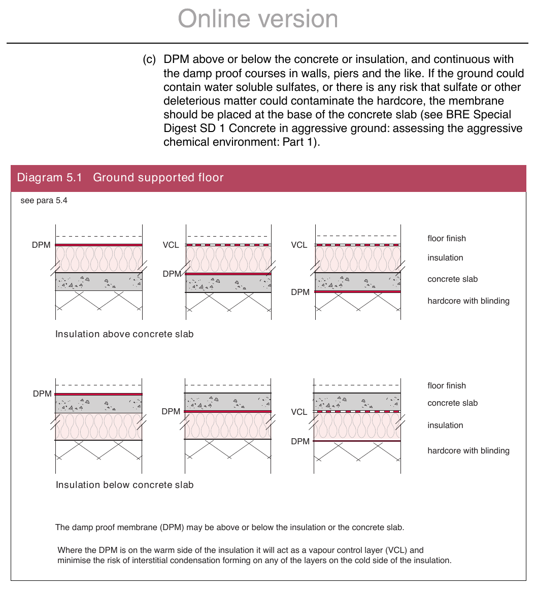
5.5A membrane below the concrete should be formed with a sheet of polyethylene, which should be at least 300 μm thick (1200 gauge) with sealed joints and laid on a bed of material that will not damage the sheet.
5.6A membrane laid above the concrete should be either polyethylene sheet as described above (but without the bedding material) or three coats of cold applied bitumen solution or similar moisture and water vapour resisting material. In each case it should be protected either by a screed or a floor finish, unless it is a waterproof membrane that will also serve as a floor finish.
5.7A membrane between the floor finish and the insulation may be polyethylene sheet as described above.
Page 23
#Source page 23
5.8Where the DPM is on the warm side of the insulation it will also act as a vapour control layer (VCL) and prevent interstitial condensation forming on any of the layers on the cold side of the insulation. Where the DPM is placed at a lower level than the insulation and no VCL is provided there is a risk of interstitial condensation which may accumulate yearonyear. However, with insulation of high vapour resistance, a vapour control layer may not be necessary but designers should use condensation software to determine if there is a risk of a yearonyear build up of interstitial condensation (see paragraph 8.2).
5.9Insulants should have sufficient compressive strength to resist the weight of the slab, the anticipated floor loading as well as any possible overloading during construction. In order to resist degradation, it is essential that insulation placed below the DPM has low water absorption. If necessary the insulant should be resistant to contaminants in the ground.
5.10A timber floor finish laid directly on concrete may be bedded in a material which may also serve as a DPM. Timber fillets laid in the concrete as a fixing for a floor finish should be treated with an effective preservative unless they are above the DPM. Some preservative treatments are described in BS 1282.
5.11BS 8102 includes recommendations for floors subject to water pressure.
Suspended timber ground floors
5.12Any suspended timber floor next to the ground should meet the requirement to resist the passage of moisture from the ground if –
(a)the ground is covered so as to resist moisture and prevent plant growth;
(b)there is an adequately ventilated air space between the ground cover and the timber; and
(c)there are damp proof courses between the timber and any material which can carry moisture from the ground.
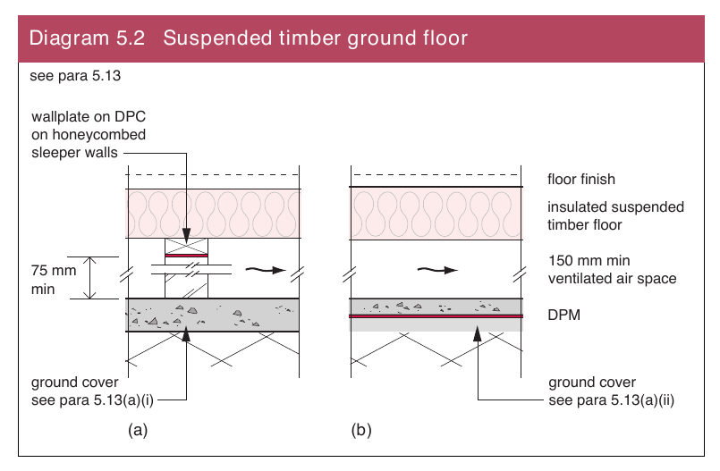
5.13A suspended timber floor next to the ground should be constructed as follows (see Diagram 5.2) –
(a)ground cover –
(i)unreinforced concrete at least 100 mm thick to mix ST 1 in BS 85001. The concrete should be laid on a hardcore bed of clean, broken brick or any other inert material free from water soluble sulfates in quantities which could damage the concrete (see Diagram 5.2a); or
(ii)concrete, composed as described above, at least 50 mm thick, laid on at least 300 μm (1200 gauge) polyethylene sheet with sealed joints, and itself laid on a bed of material which will not damage the sheet (see Diagram 5.2b);
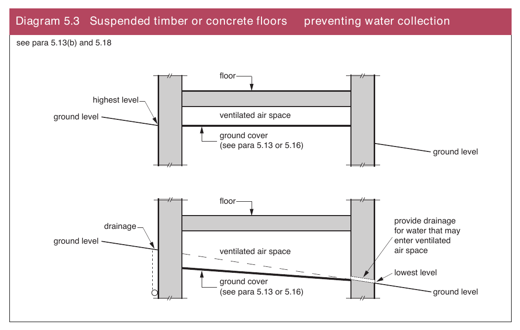
(b)to prevent water collecting on the ground cover, either the top of the ground cover should be entirely above the highest level of the adjoining ground or, on sloping sites, drainage should be installed on the outside of the upslope side of the building (see Diagram 5.3);
Page 24
#Source page 24
(c)with a ventilated air space measuring at least 75 mm from the ground cover to the underside of any wall plates and at least 150 mm to the underside of the suspended timber floor (or insulation if provided). Two opposing external walls should have ventilation openings placed so that the ventilating air will have a free path between opposite sides and to all parts. The openings should be not less than either 1500 mm2/m run of external wall or 500 mm2/m2 of floor area, whichever gives the greater opening area. Any pipes needed to carry ventilating air should have a diameter of at least 100 mm. Ventilation openings should incorporate suitable grilles which prevent the entry of vermin to the subfloor but do not resist the air flow unduly. If floor levels need to be nearer to the ground to provide level access, subfloor ventilation may be provided through offset (periscope) ventilators; and
(d)with a damp proof course of impervious sheet material, engineering brick or slates in cement mortar or other material which will prevent the passage of moisture. Guidance on choice of materials is given in BS 56283.
Diagram 5.2 Suspended timber ground floor
Page 25
#Source page 25
Diagram 5.3 Suspended timber or concrete floors preventing water collection
Suspended concrete ground floors
5.14Any suspended floor of precast or in situ concrete, including beam and block floors, next to the ground should meet the requirement to resist the passage of moisture from the ground if it will adequately resist the passage of moisture to the upper surface and if the reinforcement is protected against moisture.
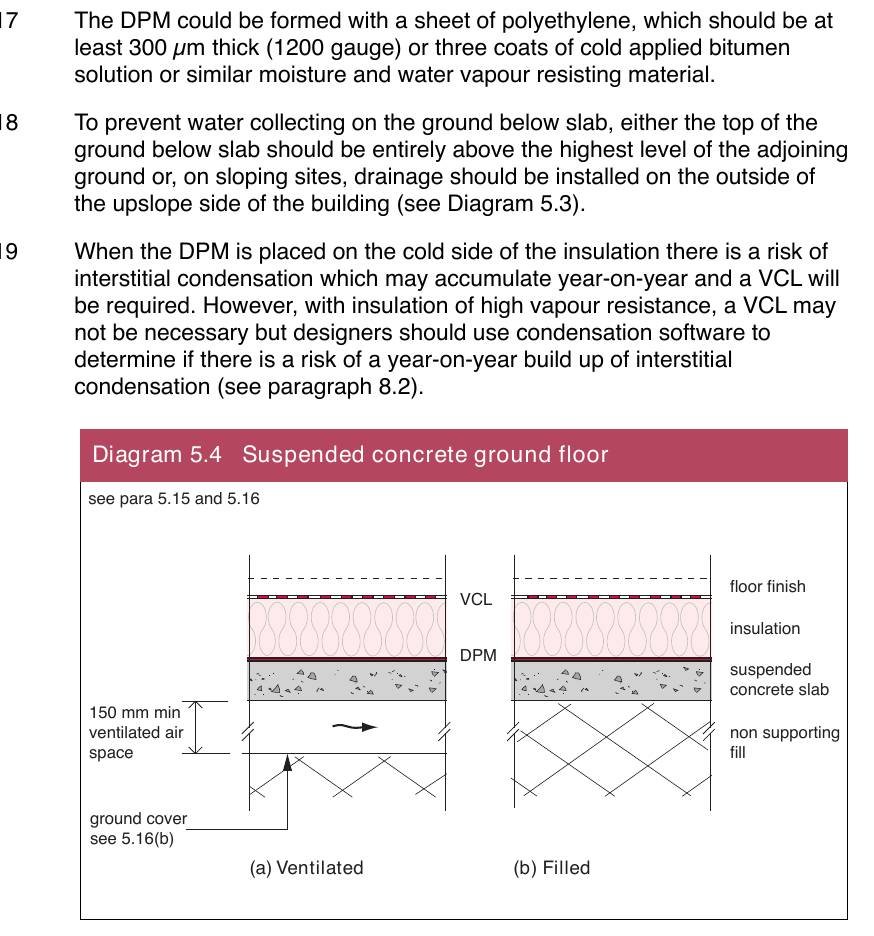
5.15A suspended concrete ground floor should be constructed as follows (see Diagram 5.4) –
(a)in situ concrete at least 100 mm thick (but thicker if the structural design requires) of concrete designation RC28/35 to BS 8500; or
(b)precast concrete with or without infilling slabs; and
(c)reinforcing steel protected by nominal concrete cover of 40 mm if the concrete is in situ and at least the thickness required for exposure of Class XC3 in BS 8500 if the concrete is precast.
5.16A suspended concrete ground floor should meet the requirement to resist the passage of moisture from the ground if it incorporates (see Diagram 5.4) –
(a)a damp proof membrane; and
(b)where there is a ventilated air space below the floor it should measure at least 150 mm clear from the ground to the underside of the floor (or insulation if provided). The ground below the floor should be free of organic material.
Two opposing external walls should have ventilation openings placed so that the ventilating air will have a free path between opposite sides and to all parts.
Page 26
#Source page 26
The openings should be not less than either 1500 mm2/m run of external wall or 500 mm2/m2 of floor area, whichever gives the greater opening area.
Any pipes needed to carry ventilating air should have a diameter of at least 100 mm. Ventilation openings should incorporate suitable grilles which prevent the entry of vermin to the subfloor but do not resist the air flow unduly.
If floor levels need to be nearer to the ground to provide level access, subfloor ventilation can be provided through offset (periscope) ventilators.
5.17The DPM could be formed with a sheet of polyethylene, which should be at least 300 μm thick (1200 gauge) or three coats of cold applied bitumen solution or similar moisture and water vapour resisting material.
5.18To prevent water collecting on the ground below slab, either the top of the ground below slab should be entirely above the highest level of the adjoining ground or, on sloping sites, drainage should be installed on the outside of the upslope side of the building (see Diagram 5.3).
5.19When the DPM is placed on the cold side of the insulation there is a risk of interstitial condensation which may accumulate yearonyear and a VCL will be required. However, with insulation of high vapour resistance, a VCL may not be necessary but designers should use condensation software to determine if there is a risk of a yearonyear build up of interstitial condensation (see paragraph 8.2).
Page 27
#Source page 27
Section 6 Walls
General
6.1This section gives guidance on the resistance to the passage of moisture from the ground and the resistance to the passage of moisture from the outside caused by the weather in relation to the following walls –
(a)internal and external walls subject to the passage of moisture from the ground (see paragraphs 6.3 to 6.6);
(b)external walls exposed to precipitation covering –
(i)deflecting penetrating water to the outside (see paragraph 6.8);
(ii)external solid walls (see paragraphs 6.9 to 6.12);
(iii) external cavity walls (see paragraphs 6.13 to 6.17);
(iv)framed external walls (see paragraph 6.18);
(v)cracking in external walls (see paragraph 6.19);
(vi)cladding systems for external walls (see paragraphs 6.20 to 6.30); and
(vii) joint at doors and windows in external walls and door thresholds (see paragraphs 6.31 to 6.33).
The definition of wall does not include windows, doors and similar openings, but includes the joint between their frames and the wall.
6.2Walls should –
(a)resist the passage of moisture from the ground to the inside of the building; and
(b)not be damaged by moisture from the ground and not carry moisture from the ground to any part of the wall which would be damaged by it, and, if the wall is an external wall –
(i)resist the penetration of precipitation to components of the structure that may be damaged by moisture; and
(ii)resist the penetration of precipitation to the inside of the building.
Resistance to moisture from the ground
General
6.3Any internal or external wall should meet the requirement to resist the passage of moisture from the ground if a damp proof course is provided.
Internal and external walls
6.4An internal or external wall should meet the requirement to resist the passage of moisture from the ground if it is constructed as follows (unless it is subject to ground water pressure, in which case follow the guidance referred to in paragraph 6.6) –
Page 28
#Source page 28
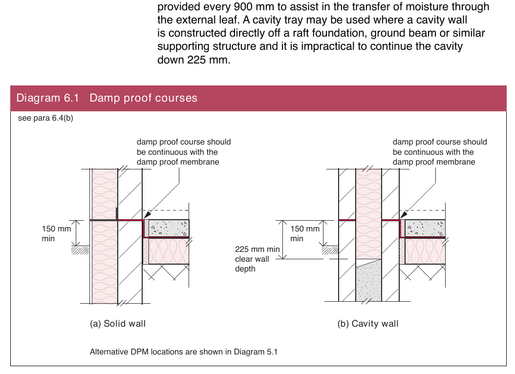
(a)damp proof course of bituminous material, polyethylene, engineering bricks or slates in cement mortar or any other material that will prevent the passage of moisture. The damp proof course should be continuous with any damp proof membrane in the floor;
(b)if the wall is an external wall, the damp proof course should be at least 150 mm above the level of the adjoining ground (see Diagram 6.1), unless the design is such that a part of the building will protect the wall; and
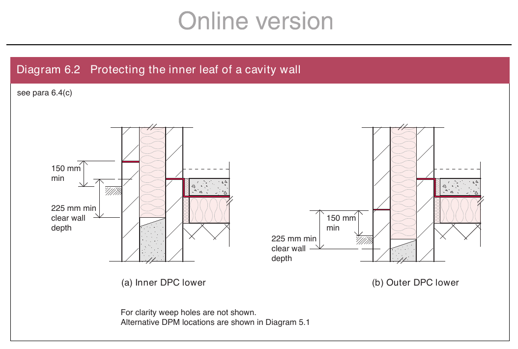
(c)if the wall is an external cavity wall (see Diagram 6.2), the cavity should be taken down at least 225 mm below the level of the lowest damp proof course, or a cavity tray should be provided to deflect penetrating water towards the outer face so as to prevent precipitation passing into the inner leaf. Weep holes should be provided every 900 mm to assist in the transfer of moisture through the external leaf. A cavity tray may be used where a cavity wall is constructed directly off a raft foundation, ground beam or similar supporting structure and it is impractical to continue the cavity down 225 mm.
6.5The requirement to resist the passage of moisture from the ground can also be met by following the relevant recommendations of Clauses 4 and 5 of BS 8215.
6.6BS 8102 includes recommendations for walls subject to ground water pressure including basement walls.
Page 29
#Source page 29
Resistance to moisture from the outside
General
6.7As well as resisting the passage of moisture from the ground, an external wall should give protection against precipitation. This protection can be given by damp proof courses, trays and flashings (see paragraph 6.8), by a solid wall of sufficient thickness (see paragraphs 6.9 to 6.12), by a cavity wall (see paragraphs 6.13 to 6.17), or by an impervious or weather resisting cladding (see paragraphs 6.20 to 6.30).
Deflecting penetrating water to the outside of external walls
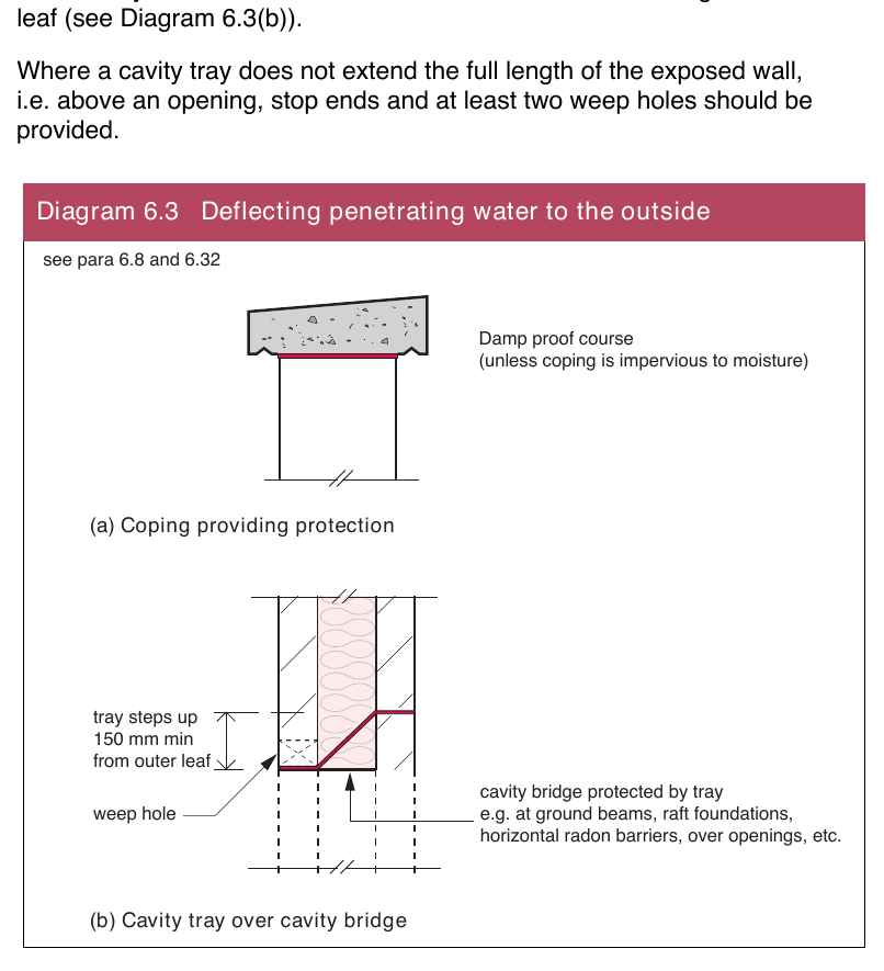
6.8External solid and cavity walls should be constructed to deflect penetrating water towards the outer face of the wall such as in the following locations –
(a)below copings at the top of walls (see Diagram 6.3(a)), unless the coping and joints will form a complete barrier to moisture;
(b)where the downward flow of water will be interrupted by a cavity bridge, such as at some types of lintel (see Diagram 6.3(b));
(c)under openings, unless there is a cill and the cill and its joints will form a complete barrier; and
(d)at abutments between walls and roofs.
Damp proof courses, cavity trays and closers should be provided and installed to ensure that water drains outwards.
Page 30
#Source page 30
Where a cavity wall is constructed directly off a raft foundation, ground beam or similar supporting structure a cavity tray should be provided with weep holes every 900 mm to assist in the transfer of moisture through the external leaf (see Diagram 6.3(b)).
Where a cavity tray does not extend the full length of the exposed wall, i.e. above an opening, stop ends and at least two weep holes should be provided.
External solid walls
6.9An external solid wall should meet the requirement if it will hold precipitation until it can be released in a dry period without penetrating to the inside of the building, or causing damage to the building. The wall thickness to achieve this will depend on the type of brick or block and on the severity of the weather including wind driven rain. A method of describing the exposure to wind driven rain is given in BS 8104; see also BS 56283 and BRE Report 262 Thermal insulation: avoiding risks.
Page 31
#Source page 31
6.10An external solid wall in conditions of “very severe exposure” should be protected by external impervious cladding.
An external solid wall in conditions of “severe exposure” should be constructed with –
(a)brickwork or stonework at least 328 mm thick, dense aggregate concrete blockwork at least 250 mm thick, or lightweight aggregate or aerated autoclaved concrete blockwork at least 215 mm thick; or
(b)brickwork or blockwork which should be rendered or be given protection equivalent to render. The mortar used in the construction of the walls should be in accordance with the guidance given in BS 9882 and the render should be designed, prepared and applied in accordance with the guidance given in BS EN 139141.
Premixed and proprietary renders should be used in accordance with manufacturer's instructions.
6.11An external solid wall should be insulated on the inside or on the outside. Where the insulation is on the inside, a cavity should be provided to give a break in the path for moisture and, where the insulation is on the outside, it should provide some resistance to the ingress of moisture to ensure the wall remains relatively dry (see Diagram 6.4).
6.12The requirement can also be met by following the relevant recommendations of BS 56283. This code describes alternative constructions to suit the severity of the exposure and the type of brick or block.
External cavity walls
6.13An external cavity wall should meet the requirement if the outer leaf is separated from the inner leaf by a drained air space, or in any other way which will prevent precipitation from being carried to the inner leaf.
6.14The construction of external cavity walls could include –
(a)an outer leaf of masonry (bricks, blocks, stone or manufactured stone);
(b)a cavity at least 50 mm wide. The cavity is to be bridged only by wall ties, cavity trays provided to prevent moisture being carried to the inner leaf, pipes and ducts, cavity insulation (see paragraphs 6.16 and 6.17), cavity barriers, firestops and cavity closures, where appropriate; and
(c)an inner leaf of masonry or frame with lining.
Masonry units should be laid on a full bed of mortar with all joints substantially and continuously filled to ensure weather resistance.
Where a cavity is to be partially filled, the residual cavity should not be less than 50 mm wide (see Diagram 6.4(c)).
6.15The requirement can also be met by following the relevant recommendations of BS 56283. The code describes factors affecting rain penetration of cavity walls.
Page 32
#Source page 32
Diagram 6.4 Insulated external walls examples
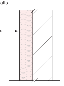
see paras 6.11, 6.14 and 6.18
| ● | ● | ● ● ● ● ● ● ● ● ● ● ● ● ● ● ● ● ● ● ● ● ● |
SolidSwalls
external 25 mm minimum protective cavity system
(a)External insulation (b) Internal insulation
Cavity walls
| 50 mm minimum | |||||
|---|---|---|---|---|---|
| ● ● ● ● ● ● ● ● ● ● ● ● ● ● ● ● ● ● ● ● ● ● |
| ● ● ● ● ● ● ● ● ● ● ● ● ● ● ● ● ● ● ● ● ● ● | ||||||
|---|---|---|---|---|---|---|
| ● |
residual cavity
(c)Partial fill insulation (d) Full fill insulation
| ● ● ● ● ● ● ● ● ● ● ● ● ● ● ● ● ● ● ● ● ● | layer | ||||||||
|---|---|---|---|---|---|---|---|---|---|
| insulation/ framing | |||||||||
| (f) Timber framed | * |
Framed walls
| layer | |||||||
|---|---|---|---|---|---|---|---|
| ● | ● ● ● ● ● ● ● ● ● ● ● ● ● ● ● ● ● ● ● ● ● ● | ||||||
| insulation/ framing |
vented and vapour control vented and vapour control drained cavity drained cavity
vertical breather counter batten membrane
breather sheathing membrane board
sheathing board
(e)Timber framed* wall with brick cladding wall with tile cladding
*Note: In the case of light steel frames, insulation should be fixed to the external face of the steel frame to minimise the risk of condensation.
Page 33
#Source page 33
Full or partial cavity insulation of external walls
6.16A full or partial fill insulating material may be placed in the cavity between the outer leaf and an inner leaf of masonry subject to the following conditions –
(a)the suitability of a wall for installing insulation into the cavity should be determined either by reference to BRE Report 262 Thermal insulation: avoiding risks or following the calculation or assessment procedure in current British or CEN standards. When partial fill materials are to be used, the residual cavity should be not less than 50 mm nominal; or
(b)a rigid (board or batt) thermal insulating material incorporated into the wall should be the subject of current certification from an appropriate body or a European Technical Approval and the work should be carried out in accordance with the requirements of that document; or
(c)other insulating materials inserted into the cavity after the wall has been constructed should have certification from an appropriate body and be installed in accordance with the appropriate installations code. The suitability of the wall for filling is to be assessed before the work is carried out and the person undertaking the work should be registered under an Approved Installer Scheme that includes an assessment of capability.
•Alternatively the insulating material should be the subject of current certification from an appropriate body or a European Technical Approval. The work should be carried out in accordance with the requirements of the certification and the operatives should be either directly employed by the holder of the certification or employed by an installer approved to operate under the certification; and
(d)when the cavity wall of an existing building is being filled, special attention should be given to the condition of the external leaf of the wall, e.g. its state of repair and type of pointing. Guidance is given in BS 82081. Some materials that are used to fill existing cavity walls may have a low risk of moisture being carried over to the internal leaf of the wall. In cases where a third party assessment of such a cavity fill material contains a method of assessing the construction of the walls and exposure risk, the procedure set out in paragraph 6.17 may be replaced by that method.
6.17BRE Report BR 262 Thermal insulation: avoiding risks provides guidance on exposure of cavity walls to driving rain. It contains a map showing exposure zones and a table giving maximum recommended exposure zones for various insulated masonry walls.
Framed external walls
6.18Any framed external wall will meet the requirement if the cladding is separated from the insulation or sheathing by a vented and drained cavity with a membrane that is vapour permeable, but resists the passage of liquid water e.g. a breather membrane, on the inside of the cavity (see Diagram 6.4(f)).
Page 34
#Source page 34
Cracking in external walls
6.19Severe rain penetration may occur through cracks in masonry external walls caused by thermal movement or by subsidence. The possibility of this occurring should be taken into account when designing a building. Detailed guidance is given in –
(a)BRE Building elements: walls, windows and doors – performance, diagnosis, maintenance, repair and avoidance of defects;
(b)BRE Report 292 Cracking in buildings; and
(c)guidance on choice of materials is given in BS 56283.
Cladding systems for external walls
6.20Cladding systems for walls should –
(a)resist the penetration of precipitation to the inside of the building; and
(b)not be damaged by precipitation and not carry precipitation to any part of the building which would be damaged by it.
6.21Cladding can be designed to protect a building from precipitation (often driven by the wind) either by holding it at the face of the building or by stopping it from penetrating beyond the back of the cladding.
6.22Any cladding will meet the requirement to resist the weather if –
(a)it is jointless or has sealed joints, and is impervious to moisture so that moisture will not enter the cladding (such as metal, plastic, glass and bituminous products); or
(b)it has overlapping dry joints, is impervious or weather resisting (including natural stone or slate, cement based products, fired clay and wood), and is backed by a material which will direct precipitation which enters the cladding towards the outer face.
6.23Some materials can deteriorate rapidly without special care and they should only be used as the weather resisting part of a cladding system if certain conditions are met (see Part B Materials and workmanship of the Building Regulations). In determining whether a material is of a suitable nature and quality for use as the weatherresisting part of an external wall no account should be taken of any paint. Also, no account should be taken of any coating, surfacing or rendering which does not itself provide all the weather resistance.
6.24Where cladding is impermeable to water vapour there should be a ventilated cavity behind it.
6.25Jointless materials and materials with sealed joints should allow for structural and thermal movement.
6.26Dry joints between cladding units should be designed so that precipitation will not pass through them, or the cladding should be designed so that precipitation which enters the joints will be directed towards the exposed face without it penetrating beyond the back of the cladding.
Whether dry joints are suitable or not will depend on the design of the joint or the design of the cladding and the severity of the exposure to wind and rain.
Page 35
#Source page 35
6.27Each sheet, tile and section of cladding should be securely fixed. Guidance as to appropriate fixing methods is given in BS 80006. Particular care should be taken with detailing and workmanship at the junctions between cladding and window and door openings as they are vulnerable to moisture ingress.
6.28Insulation can be incorporated into the construction provided it is either protected from moisture or is unaffected by it.
6.29Where cladding is supported by timber components or is on the façade of a timber framed building, the space between the cladding and the building should be ventilated to ensure rapid drying of any water that penetrates the cladding.
6.30The requirement to resist the passage of moisture from the weather can also be met by following the relevant recommendations of –
(a) BS CP 143 for sheet roof and wall coverings made from the following materials –
Part 1: 1958 for corrugated and troughed aluminium; Part 5: 1964 for zinc; Part 10: 1973 for galvanized corrugated steel; Part 12: 1970 for copper; and Part 15: 1973 for aluminium;
Recommendations for lead are included in BS 6915;
(b)BS 8219 for profiled fibre cement;
(c)BS 8200 for the design of nonloadbearing external vertical enclosures of buildings;
(d)BS 8297 for design and installation of nonloadbearing precast concrete cladding;
(e)BS 8298 for design and installation of natural stone cladding and lining;
(f)Metal Cladding and Roofing Manufacturers Association (MCRMA) Technical Paper 6 Profiled metal roofing design guide; and
(g)MCRMA Technical Paper 9 Composite roof and wall cladding panel design guide.
These documents describe the materials and contain design considerations including recommendations for fixing.
Joint at doors and windows in external walls
6.31The joint between walls and door or window frames should –
(a)resist the penetration of precipitation to the inside of the building; and
(b)not be damaged by precipitation and not permit precipitation to reach any part of the building which would be damaged by it.
Page 36
#Source page 36
6.32Damp proof courses should be provided to direct moisture towards the outside –
(a)where the downward flow of moisture would be interrupted at an obstruction, e.g. at a lintel (see Diagram 6.3(b));
(b)where cill elements, including joints, do not form a complete barrier to the transfer of precipitation, e.g. under openings, windows and doors; and
(c)where reveal elements, including joints, do not form a complete barrier to the transfer of rain and snow, e.g. at openings, windows and doors.
Door thresholds in external walls
6.33Guidance on weather protection of accessible thresholds is given in –
(a)BRE Good Building Guide 47 Level external thresholds: reducing moisture penetration and thermal bridging; and
(b)The Stationery Office (TSO) document Accessible thresholds in new buildings: guidance for house builders and designers.
See also BS 8300 which provides guidance on the design of entrance thresholds to meet the needs of disabled people.
Page 37
#Source page 37
Section 7 Roofs
General
7.1Roofs should –
(a)resist the passage of moisture caused by the weather to the inside of the building; and
(b)not be damaged by the weather and not carry precipitation to any part of the building which would be damaged by it.
Resistance to moisture from the outside
7.2Roofing can be designed to protect a building from the weather either by holding the precipitation at the face of the roof or by stopping it from penetrating beyond the back of the roofing system.
7.3Any roof will meet the requirement if –
(a)it is jointless or has sealed joints, and is impervious to moisture (including metal, plastic, glass and bituminous products) so that moisture will not enter the roofing system; or
(b)it has overlapping dry joints, is impervious or weather resisting (such as natural stone or slate, cement based products, fired clay and wood), and is backed by a material which will direct precipitation which enters the roof towards the outer face (as with underlay).
Some materials can deteriorate rapidly without special care and they should only be used as the weather resisting part of a roofing system if certain conditions are met (see Part B Materials and workmanship of the Building Regulations). In determining whether a material is of a suitable nature and quality for use as the weather resisting part of a roof no account may be taken of any paint. Also, no account may be taken of any coating or rendering which does not itself provide all the weather resistance.
7.4Where cladding is impermeable to water vapour there should be a ventilated air space behind the cladding.
7.5Jointless materials and materials with sealed joints should allow for structural and thermal movement.
7.6Dry joints between roofing sheets should be designed so that precipitation will not pass through them, or the system should be designed so that precipitation which enters the joints will be drained away without penetrating beyond the back of the roofing system.
Whether dry joints are suitable or not will depend on the design of the joint or the design of the roofing system and the severity of the exposure to wind and rain.
7.7
Each sheet, tile and section of roof should be fixed in an appropriate manner. Guidance as to appropriate fixing methods is given in BS 80006.
Page 38
#Source page 38
7.8
The requirement to resist the passage of moisture from the weather can also be met by following the relevant recommendations of –
(a) BS CP 143 for sheet roof and wall coverings made from the following materials –
Part 1: 1958 for corrugated and troughed aluminium; Part 5: 1964 for zinc; Part 10: 1973 for galvanized corrugated steel; Part 12: 1970 for copper; and Part 15: 1973 for aluminium;
Recommendations for lead are included in BS 6915;
(b)BS 8200 for the design of nonloadbearing external vertical enclosures of buildings;
(c)BS 8219 for profiled fibre cement;
(d)MCRMA Technical Paper 6 Profiled metal roofing design guide; and
(e)MCRMA Technical Paper 9 Composite roof and wall cladding panel design guide.
These documents describe the materials and contain design considerations including recommendations for fixing.
Page 39
#Source page 39
Section 8 Condensation
Interstitial condensation
8.1Regulation 29 (Condensation) applies only to dwellings.
8.2A dwelling should meet the requirement to avoid any harmful effects caused by interstitial condensation if it is designed and constructed in accordance with BS 5250. Guidance is also given in the BRE Report BR 262 Thermal insulation: avoiding risks.
Page 40
#Source page 40
Appendix Publications referred to
British Standards (BS)
BS EN 9982: 2003 Specification for mortar for masonry. Masonry mortar.
BS EN 139141:2005 Design, preparation and application of external rendering and internal plastering. External rendering.
BS 1282: 1999 Wood preservatives. Guidance on choice, use and application.
BS 5250: 2011 Code of practice for the control of condensation in buildings.
BS 56283: 2005 Code of practice for use of masonry. Materials and components, design and workmanship.
BS 5930: 1999 Code of practice for site investigations.
BS 6915: 2001 Design and construction of fully supported lead sheet roof and wall coverings. Code of practice.
BS 80006: 1990 Workmanship on building sites. Code of practice for slating and tiling of roofs and claddings.
BS 8102: 2009 Code of practice for protection of below ground structures against water from the ground.
BS 81031: 1995 Structural design of low rise buildings. Code of practice for stability, site investigation, foundations and ground floor slabs for housing. AMD 8980 1995.
BS 8104: 1992 Code of practice for assessing exposure of walls to wind driven rain. AMD 8358 1995.
BS 8200: 1985 Code of practice for the design of nonloadbearing external vertical enclosures of buildings.
BS 82081: 1985 Guide to assessment of suitability of external cavity walls for filling with thermal insulants. Existing traditional cavity construction. AMD 4996 1985.
BS 8215: 1991 Code of practice for design and installation of damp proof courses in masonry construction.
BS 8219: 2001 Installation of sheet roof and wall coverings. Profiled fibre cement. Code of practice.
BS 8297: 2000 Code of practice for design and installation of non loadbearing precast concrete cladding. AMD 11064 2000, AMD 13018 2000.
BS 8298: 1994 Code of practice for design and installation of natural stone cladding and lining.
BS 8300: 2009 +A1: 2010 Design of buildings and their approaches to meet the needs of disabled people. Code of practice.
Page 41
#Source page 41
BS 85001: 2006 Concrete. Complementary British Standard to BS EN 2061. Method of specifying and guidance for the specifier.
CP 143 Code of Practice for sheet roof and wall coverings.
Part 1: 1958 Aluminium, corrugated and troughed. PD 4346 1961. Part 5: 1964 Zinc. Part 10: 1973 Galvanized corrugated steel. Part 12: 1970 Copper. AMD 863 1972, AMD 5193 1987. Part 15: 1973 Aluminium. AMD 4473 1984.
Amendments are shown by either an AMD or PD number and year of issue.
British Research Establishment (BRE)
BRE Building elements: walls, windows and doors – performance, diagnosis, maintenance, repair and avoidance of defects, 1998. Digest 276 Hardcore, 1992. Digest 318 Site investigation for lowrise building: desk studies, 1987. Digest 322 Site investigation for lowrise building: procurement, 1987. Digest 348 Site investigation for lowrise building: the walkover survey, 1989. Digest 381 Site investigation for lowrise building: trial pits, 1993. Digest 383 Site investigation for lowrise building: soil description, 1993. Digest 411 Site investigation for lowrise building: direct investigations, 1995. Digest 427 Lowrise buildings on fill: classification and loadcarrying characteristics: Part 1, 1997. Digest 427 Lowrise buildings on fill: site investigation, ground movement and foundation design: Part 2, 1998. Digest 427 Lowrise buildings on fill: engineered fill: Part 3, 1998. Good Building Guide 47 Level external thresholds: reducing moisture penetration and thermal bridging, 2001. Good Building Guide 73 Radon protection for new domestic extensions and conservatories with solid concrete ground floors, 2008. Report 262 Thermal insulation: avoiding risks, 2002. Report 267 Major alterations and conversions: a BRE guide to radon remedial measures in existing dwellings, 1994. Report 292 Cracking in buildings, 1996. Report 413 Radon: guidance on protective measures for new buildings in Northern Ireland, 2001.
Page 42
#Source page 42
Report 424 Building fill: Geotechnical aspects. 2nd edition, 2001.
Special Digest 1 Concrete in aggressive ground: assessing the aggressive chemical environment: Part 1, 2005.
Construction Industry Research and Information Association (CIRIA)
C506Lowcost options for prevention of flooding from sewers, 1998.
Communities and Local Government (CLG)
Improving the flood performance of new buildings – flood resilient construction, 2007.
Preparing for floods: interim guidance for improving the flood resistance of domestic and small business properties, 2002. (reprinted with amendments 2003).
Approved Document H Drainage and Waste Disposal, 2010.
Department of Environment for Northern Ireland (DOE NI)
PPS 15 Planning and flood risk, 2006.
Health Protection Agency
Radon in Dwellings in Northern Ireland: 2009 review and atlas, 2009.
Metal Cladding and Roofing Manufacturers Association (MCRMA)
Technical Paper 6 Profiled metal roofing design guide, revised edition 2004.
Technical Paper 9 Composite roof and wall cladding panel design guide, 1995.
Scottish Office
Design guidance on flood damage to dwellings, 1996.
The Stationery Office (TSO)
Accessible thresholds in new buildings: guidance for house builders and designers, 1999.
Other publications
Technical Booklet B: 2012 – Materials and workmanship
Page 43
#Source page 43
Technical Booklets
The following list comprises the series of Technical Booklets prepared by the Department for the purpose of providing practical guidance with respect to the technical requirements of the Building Regulations (Northern Ireland) 2012.
Technical Booklet B Materials and workmanship
Technical Booklet C Site preparation and resistance to contaminants and moisture Technical Booklet D Structure
Technical Booklet E Fire safety
Technical Booklet F1 Conservation of fuel and power in dwellings
Technical Booklet F2 Conservation of fuel and power in buildings other than dwellings Technical Booklet G Resistance to the passage of sound
Technical Booklet H Stairs, ramps, guarding and protection from impact Technical Booklet J Solid waste in buildings
Technical Booklet K Ventilation
Technical Booklet L Combustion appliances and fuel storage systems Technical Booklet N Drainage
Technical Booklet P Sanitary appliances, unvented hot water storage systems and reducing the risk of scalding Technical Booklet R Access to and use of buildings
Technical Booklet V Glazing
Any person who intends to demonstrate compliance with the Building Regulations by following the guidance given in a Technical Booklet is advised to ensure that the guidance is current on the date when the plans are deposited or notice given to the district council.