Northern Ireland Technical booklet D
Technical booklet D - Structure - October 2012
Library captured 10 September 2026 · Source updated 22 August 2026
● Finance and ● Personnel
#Source page 1
Department of
● Finance and ● Personnel
G u i d a n c e
Te c h n i c a l B o o k l e t
D
S tr uc t ure
October 2012
Page 2
#Source page 2
Contents page
Introduction Technical Booklets 3
This Technical Booklet 3
Protected buildings 4
Other legislation 4
Part D Regulations 6
Guidance – Performance and introduction to provisions Regulation 30 in Part D Stability 7
Regulation 31 in Part D Disproportionate collapse 9
Section 1 General
Section 2 Codes and standards relevant to all building types
Demonstrating compliance with regulation 30 in Part D Stability 12
Demonstrating compliance with regulation 31 in Part D Disproportionate collapse 13
Using alternative codes and standards to satisfy regulation 30 in Part D 14
For single family houses and small buildings 15
Section 3 Disproportionate collapse
Houses, annexes and small single storey buildings
#Source page 3
Section 4 Single family houses, annexes and small single storey buildings
Application and presentation 22
4A Basic requirements for stability 23
4B Timber floor, ceiling and roof members in a house 24
Determination of dimensions of timber members 24
Spans, sizes and spacings for timber members 27
Ceiling joists and binders supporting ceiling joists 32
Rafters and purlins supporting rafters 35
Purlins supporting decking or sheeting 55
4C Masonry walls. Part 1 Masonry walls for houses 58
Conditions relating to the building 60
Conditions relating to the wall 65
Construction materials and workmanship 66
Wall restraints Vertical restraint by buttressing walls, piers and chimneys 71
Wall restraints Lateral restraint by floors and roofs 73
Openings, recesses, overhangs and chases 77
Wall thickness 79
4C Masonry walls. Part 2 Masonry walls for annexes and small single storey buildings 81
Application of this Part of the Section 81
Proportions for masonry chimneys above the roof surface 86
Strip foundations of plain concrete 87
Appendix Publications referred to 91
Houses, annexes and small single storey buildings
Technical Booklets
#Source page 4
Introduction
Technical Booklets
This Technical Booklet, which takes effect on 31st October 2012, is one of a series that has been prepared by the Department of Finance and Personnel (the Department) for the purpose of providing practical guidance with respect to the technical requirements of the Building Regulations (Northern Ireland) 2012 (the Building Regulations).
At the back of each Technical Booklet is a list of all the Technical Booklets that have been prepared and published by the Department for this purpose.
The guidance given in a Technical Booklet includes performance standards and design provisions relating to compliance with specific aspects of the Building Regulations for the more common building situations.
If the guidance in a Technical Booklet is followed there will be a presumption of compliance with the requirements of those Building Regulations covered by that guidance. However, this presumption can be overturned, so simply following the guidance does not guarantee compliance. For example, if a particular circumstance is not one of the more common building situations the design provisions given in the Technical Booklet may not be appropriate.
There are likely to be alternative ways of demonstrating compliance with the relevant requirements of the Building Regulations other than by following a design provision given in a Technical Booklet. There is therefore no obligation to adopt any particular provision set out in a Technical Booklet, should you decide to comply in some other way. However, you will have to demonstrate that your alternative solution meets the relevant requirements of the Building Regulations by those other means.
This Technical Booklet
Requirements
The guidance contained in this Technical Booklet relates only to the requirements of regulations 30 and 31. The work will also have to comply with all other relevant requirements of the Building Regulations.
Materials and workmanship
Any building work which is subject to requirements imposed by Part A of the Building Regulations should be carried out in accordance with regulation 23 of those regulations. Guidance on meeting these requirements for materials and workmanship is given in Technical Booklet B which supports Part B.
Protected buildings
#Source page 5
The Building Regulations are made for specific purposes, primarily securing the health, safety, welfare and convenience of people and for the conservation of fuel and power. Standards and technical approvals are relevant guidance to the extent that they relate to these purposes. However, they may also address other aspects of performance such as serviceability, or aspects which although they relate to health and safety are not covered by the Building Regulations.
Named standards
Where this Technical Booklet makes reference to a named standard, the relevant version of the standard is the one listed in the Appendix. However, if this version has been replaced or updated by the issuing standards body, the new version may be used as a source of guidance provided that it continues to address the relevant requirements of the Building Regulations.
Diagrams
The diagrams in this Technical Booklet supplement the text. They do not show all the details of construction and are not intended to illustrate compliance with any other requirement of the Building Regulations. They are not necessarily to scale and should not be used as working details.
Protected buildings
District councils have a duty to take account of the desirability to preserve the character of protected buildings when carrying out their functions under Building Regulations. Therefore, where work is to be carried out to a protected building to comply with Part D or any other Part of the Building Regulations, special consideration may be given to the extent of such work for compliance where it would unacceptably alter the character or appearance of the building. Protected buildings are defined in Article 3A(2) of the Building Regulations (Northern Ireland) Order 1979 (as amended).
Other legislation
The provisions of this Technical Booklet relate to the requirements of Building Regulations and do not include measures which may be necessary to meet the requirements of other legislation. Such other legislation may operate during the design or construction stages or when a building is brought into use and can extend to cover aspects which are outside the scope of the Building Regulations.
Construction (Design And Management) Regulations (Northern Ireland) 2007
The Construction (Design and Management) Regulations (Northern Ireland) 2007 impose requirements which affect building design. These include, amongst other things, the need for coordination, cooperation and communication between all parties in the construction process. The regulations also require –
(a)those undertaking design works, as part of a business, to be competent.
Page 6
#Source page 6
(b)an indication of the proposed construction sequence, if this is not obvious to a competent contractor. This is particularly relevant to refurbishments and new basements to existing buildings.
Note that these regulations apply to nondomestic clients, designers and contractors no matter what the duration or size of the project.
The Workplace (Health, Safety and Welfare) Regulations (Northern Ireland) 1993
The Workplace (Health, Safety and Welfare) Regulations (Northern Ireland) 1993 (the Workplace Regulations) contain some requirements which affect building design. The main requirements are now covered by the Building Regulations, but for further information see – The Workplace Regulations and the Workplace Health, Safety and Welfare Approved Code of Practice.
The Workplace Regulations apply to the common parts of flats and similar buildings if people such as cleaners, wardens and caretakers are employed to work in these common parts. Where the requirements of the Building Regulations that are covered by Part D do not apply to dwellings, the provisions may still be required in the situations described above in order to satisfy the Workplace Regulations.
PART D
#Source page 7
Part D Regulations
Part D (comprising regulations 30 and 31) of the Building Regulations, which sets out the requirements for Structure, has been replicated below for the convenience of the user of this Technical Booklet and is taken directly from the Building Regulations (Northern Ireland) 2012.
Any person who intends to demonstrate compliance with the Building Regulations by following the guidance given in this Technical Booklet is advised to ensure that the regulations below, are current on the date when plans are deposited or notices given to the district council.
As Part A (comprising regulations 1 to 21) of the Building Regulations sets out the Interpretation along with the procedural requirements relating to the application of the regulations, the Department advises that all Parts of the Building Regulations are read in conjunction with Part A of those regulations.
The Building Regulations (Northern Ireland) 2012 and any subsequent amendment/s may be viewed by following the links from the Department’s website at “www.buildingregulationsni.gov.uk”.
PART D
Structure
Stability
30.A building shall be designed and constructed so that the combined dead, imposed and wind loads are sustained and transmitted to the ground, taking into account the nature of the ground—
(a)safely; and
(b)without impairing the safety of any part of another building.
Disproportionate collapse
31.A building shall be designed and constructed so that in the event of damage occurring to any part of the building, the extent of any resulting collapse will not be disproportionate to the cause of the damage.
Regulation 30 in Part D Stability
#Source page 8
Guidance – Performance and introduction to provisions
Regulation 30 in Part D Stability
Performance
0.1It is the view of the Department that the requirements of regulation 30 in Part D will be met when the structure of a building is designed and constructed —
(a)so as to ensure the safety of those people who are in or about the building, having due regard to the nature of the ground, the loads imposed by the building and the loads imposed on the building; and
(b)so as not to impair the stability of any part of any other building.
Satisfying regulation 30 in Part D Codes and standards relevant to all building types
For all building types, following the recommendations given in the documents listed in paragraphs 2.2 to 2.9 should demonstrate compliance with the requirements of regulation 30 in Part D. However, where they do not give precise guidance, consideration should be given to paragraph 0.2. Alternative codes and standards to those listed in paragraphs 2.2 to 2.9 may be used to satisfy the requirements of the Building Regulations.
Further considerations
0.2The safety of a structure depends on the successful combination of design and completed construction, particularly —
(a)identification of hazards to which the structure is likely to be subjected and assessment of the risks using the conditions that can reasonably be foreseen during future use;
(b)the selfweight of the building;
(c)the loads imposed on the building including those arising from climatic conditions;
(d)combinations of (a), (b) and (c);
(e)properties of materials;
(f)safety factors;
(g)the nature of the ground;
(h)impact on and by other buildings; and
(i)workmanship.
The numeric values of safety factors, whether expressed explicitly or implicitly in design equations, or design values, should be derived from considerations of the above aspects of design and construction as a whole. A change in any one of these aspects may disturb the safety of the structure.
Page 9
#Source page 9
Actions used in calculations should allow for possible dynamic, concentrated and peak load effects that may occur. The design should ensure that the effects of actions do not cause a situation of irreversible serviceability limit states.
Alternative approach to satisfying Regulation 30 in Part D in relation to single family houses, annexes and small single storey buildings
0.3For a single family house of not more than 3 storeys in height, an annex or a small single storey building, a designer may wish to follow the guidance given in Section 4 of this Technical Booklet to demonstrate compliance with the requirements of Regulation 30 in Part D.
Introduction to provisions in Section 4
Part 4A of Section 4 provides guidance on the basic requirements for stability.
The guidance in Part 4B of Section 4 is concerned with various timber members. Provisions are given in relation to the strength, loadings, sizes and spacings of those timber members.
Part 4C of Section 4 provides guidance on the design of masonry walls. Provisions are given regarding conditions relating to the building, conditions relating to the wall and wall thickness.
Part 4D of Section 4 provides guidance on the proportions for masonry chimneys above the roof surface.
The guidance in Part 4E of Section 4 is concerned with the design of concrete strip foundations.
Regulation 31 in Part D Disproportionate collapse
#Source page 10
Performance
0.4It is the view of the Department that the requirements of regulation 31 in Part D will be met when a building is designed and constructed so as to ensure the safety of people in or about the building. The building design should also take into consideration accidental actions to which the structure may be subjected and the buildings ability to sustain a limited extent of damage or failure without a disproportionate level of collapse.
Satisfying regulation 31 in Part D
For all building types, following the recommendations given in the documents listed in paragraph 2.10 should demonstrate compliance with the requirements of regulation 31 in Part D. Alternatively, following the procedures given in Section 3 and implementing the determined measures required to ensure robustness should demonstrate compliance with the requirements of regulation 31 in Part D.
Introduction to provisions in Section 3
Section 3 gives the procedure to determine the measures required for ensuring that the building is sufficiently robust to sustain a limited extent of damage or failure, depending on the class of the building, without collapse.
Generally
#Source page 11
Section 1 General
Generally
1.1The general rules in paragraph 4A.1 should be complied with when using Parts 4B and 4C of Section 4. Sections 3 and 4 may be used independently of each other.
Definitions
1.2In this Technical Booklet the following definitions apply –
Annex – a single storey adjunct to a house (e.g. a veranda, garage, tool shed, fuel store, lavatory etc.) with dimensions not greater than those given in paragraph 4C.40.
Buttressing wall – a wall designed and constructed to afford lateral support to another wall perpendicular to it, support being provided from the base to the top of the wall.
Cavity width – the horizontal distance between the two leaves of a cavity wall.
Compartment wall – a wall constructed as a compartment wall to meet the requirements of regulation 35(3) in Part E.
Dead load – the load due to the weight of all walls, permanent partitions, floors, roofs and finishes, including services, and all other permanent construction.
Dwelling – has the meaning assigned to it by regulation 2 in Part A of the Building Regulations.
Imposed load – the load assumed to be produced by the intended occupancy or use, including the weight of movable partitions, distributed, concentrated, impact, inertia and snow loads, but excluding wind loads.
Pier – a member which forms an integral part of a wall, in the form of a thickened section at intervals along the wall so as to afford lateral support to the wall to which it is bonded or securely tied.
Separating wall – a wall or part of a wall which is common to adjoining buildings, and constructed to meet the requirements of regulation 35(2) in Part E.
Small single storey building – a building that is not a dwelling having dimensions not greater than those given in paragraph 4C.40.
Spacing – the distance between the longitudinal centres of any 2 adjacent timber members of the same type, measured in the plane of floor, ceiling or roof structure of which the members form a part.
Page 12
#Source page 12
Span – the distance measured along the centre line of a member between the centres of any two adjacent bearings or supports.
Note: the spans given in Part 4B of Section 4 for floor joists, rafters, purlins, ceiling joists, binders and roof joists are clear spans, i.e. spans between the faces of the supports.
Supported wall – a wall to which lateral support is afforded by a combination of buttressing walls, piers or chimneys acting in conjunction with floor(s) or roof.
Wind load – the load due to the effect of wind pressure or suction.
Demonstrating compliance with regulation 30 in Part D – Stability
#Source page 13
Section 2 Codes and standards relevant to all building types
2.1
This Section is relevant to all building types and lists Codes and Standards for structural design and construction which if followed, should demonstrate compliance with the requirements of regulation 30 in Part D and regulation 31 in Part D.
Demonstrating compliance with regulation 30 in Part D – Stability
Loadings
2.2Eurocode 1 Action on structures BS EN 199111 (1). BS EN 199113 (1). BS EN 199114 (1).
Design and construction
Reinforced prestressed or plain concrete
2.3Eurocode 2 Design of concrete structures BS EN 199211 (1). BS EN 199212 (1).
Steel
2.4Eurocode 3 Design of steel structures BS EN 199311 (1). BS EN 199312 (1). BS EN 199313 (1). BS EN 199315 (1). BS EN 199318 (1). BS EN 1993110 (1).
Composite steel and concrete
2.5
Eurocode 4 Design of composite concrete and steel structures BS EN 199411 (1). BS EN 199412 (1).
(1) To be read in conjunction with the associated National Annex and BS EN 1990.
Demonstrating compliance with regulation 31 in Part D – Disproportionate collapse
#Source page 14
Timber (Generally)
2.6
Eurocode 5 Design of timber structures BS EN 199511 (1). BS EN 199512 (1).
Masonry
2.7
Eurocode 6 Design of masonry structures BS EN 199611 (1). BS EN 199612 (1). BS EN 19963 (1).
Foundations (Generally)
2.8Eurocode 7 Geotechnical Design BS EN 19971 (1).
Aluminium
2.9Eurocode 9 Design of aluminium structures BS EN 199911 (1). BS EN 199912 (1). BS EN 199913 (1).
Demonstrating compliance with regulation 31 in Part D – Disproportionate collapse
Robustness
2.10Eurocode 1 Action on structures BS EN 199117 (1).
(1) To be read in conjunction with the associated National Annex and BS EN 1990.
Using alternative codes and standards to satisfy regulation 30 in Part D
#Source page 15
All buildings
2.11As an alternative to the codes and standards referenced in paragraphs 2.2 to 2.9, the documents referred to in paragraphs 2.12 to 2.19, which were withdrawn by the British Standards Institution on 31 March 2010, may be used to satisfy the requirements of the Building Regulations. However, designers will be required to demonstrate appropriate use of withdrawn standards in the circumstances of the building work. Using withdrawn British Standards may continue to be acceptable where it can be demonstrated that design reliability can be achieved. Particular care must be exercised in relation to withdrawn codes used to calculate wind and snow loads where the effects of climate change may render these unsafe. Consistency of design approach is required and designs should not inappropriately mix Eurocodes and withdrawn British Standards.
Structural loadings
2.12BS 6399: Part 1 (excluding imposed roof loads). BS 6399: Part 2. BS 6399: Part 3.
Reinforced prestressed or plain concrete
2.13BS 8110: Part 1. BS 8110: Part 2. BS 8110: Part 3.
Steel
2.14BS 5950: Part 1. BS 5950: Part 2. BS 5950: Part 5.
Composite steel and concrete
2.15BS 5950: Part 3. BS 5950: Part 4.
Timber (Generally)
2.16BS 5268: Part 2. BS 5268: Part 3.
For single family houses and small buildings
#Source page 16
Masonry
2.17BS 5628: Part 1. BS 5628: Part 2. BS 5628: Part 3.
2.18Foundations (Generally) BS 8004.
2.19Aluminium BS 8118: Part 1. BS 8118: Part 2.
For single family houses and small buildings
General
2.20For a house of not more than 3 storeys in height, an annex or a small single storey building, an alternative way of meeting the requirement of regulation 30 in Part D is to follow the recommendations given in the publications listed in paragraphs 2.21 to 2.24.
Foundations for houses and small buildings
2.21BS 8103: Part 1.
Suspended concrete floors for houses
2.22BS 8103: Part 4.
Timber floors and roofs for houses
2.23BS 8103: Part 3.
Masonry walls for housing and small single storey buildings
2.24BS 8103: Part 2.
Application
#Source page 17
Section 3 Disproportionate collapse
Application
3.1This Section gives the procedure to determine measures to ensure the robustness of any building.
Procedure
Determination of measures to ensure robustness
3.2To ensure that a building is sufficiently robust to sustain a limited extent of damage –
(a)the class of building should be determined using Table 3.1; and
(b)the required measures, described in paragraphs 3.4 to 3.11 for the class of building determined, should be followed.
The design of the required measures must be undertaken by a suitably qualified person, such as a chartered structural engineer.
Designation of different building classes within a building
3.3In some circumstances it may be appropriate to treat some parts of a building as belonging to a different building class. The designation of parts of a building as belonging to different classes should only be undertaken on the recommendation of a suitably qualified person, such as a chartered structural engineer.
Page 18
#Source page 18
| Table 3.1 Building classes | |
|---|---|
| Class | Building type by height, floor area and/or occupancy |
| 1 | Single family houses of not more than 4 storeys Agricultural buildings Buildings into which people rarely go, provided no part of the building is no closer to another building, or area where people go, than a distance of 1.5 times the building height |
| 2A | 5 storey single family houses Hotels, flats, maisonettes and other residential buildings not more than 4 storeys Offices of not more than 4 storeys Industrial buildings not more than 3 storeys Shops and enclosed shopping centres not more than 3 storeys, with each storey having a floor area of not more than 2000 m² Educational buildings of not more than one storey All other buildings of not more than 2 storeys, to which members of the public are admitted, with a floor area not greater than 2000 m² at each storey |
| 2B | Hotels, flats, maisonettes and other residential buildings more than 4 storeys but not more than 15 storeys Educational buildings more than 1storey but not more than 15 storeys Shops and enclosed shopping centres more than 3 storeys but not more than 15 storeys Car parking of not more than 6 storeys Grandstands accommodating not more than 5000 spectators All other buildings to which members of the public are admitted which contain floor areas greater than 2000 m² but not greater than 5000 m² at each storey |
| 3 | Grandstands accommodating more than 5000 spectators Buildings containing hazardous substances and/or processes All buildings defined above as Class 2A and 2B that exceed the maximum limits on the number of storeys and/or floor area |
| Notes: 1. For buildings intended for more than one type of use, the Class should be that pertaining to the most onerous type. 2. In determining the number of storeys in a building, each basement storey should be counted as a storey. However, basement storeys which fulfil the robustness requirements of Class 2B can be excluded. 3. This Table is not intended to be exhaustive so the Class of any building not falling into any of the groups listed should be agreed with the district council. |
Measures required to ensure robustness
#Source page 19
Class 1 buildings
3.4For a Class 1 building, provided the building has been designed and constructed in accordance with the publications specified in Section 2 or, in the case of a single family house of not more than 3 storeys, the guidance given in Section 4, to satisfy the requirements of regulation 30 in Part D, no additional measures are necessary.
Class 2A buildings
3.5For a Class 2A building, effective horizontal ties should be provided, or effective anchorage of suspended floors to walls, as described in the codes and standards listed under paragraph 3.8 for framed and loadbearing wall construction; the latter being defined in paragraph 3.11.
Class 2B buildings
3.6For a Class 2B building either (a) or (b) should be followed –
(a)provide effective –
(i)horizontal ties, as described in the codes and standards listed under paragraph 3.8 for framed and loadbearing wall construction; (the latter being defined in paragraph 3.11); and
(ii)vertical ties, as defined in the codes and standards listed under paragraph 3.8, in all supporting columns and walls; or
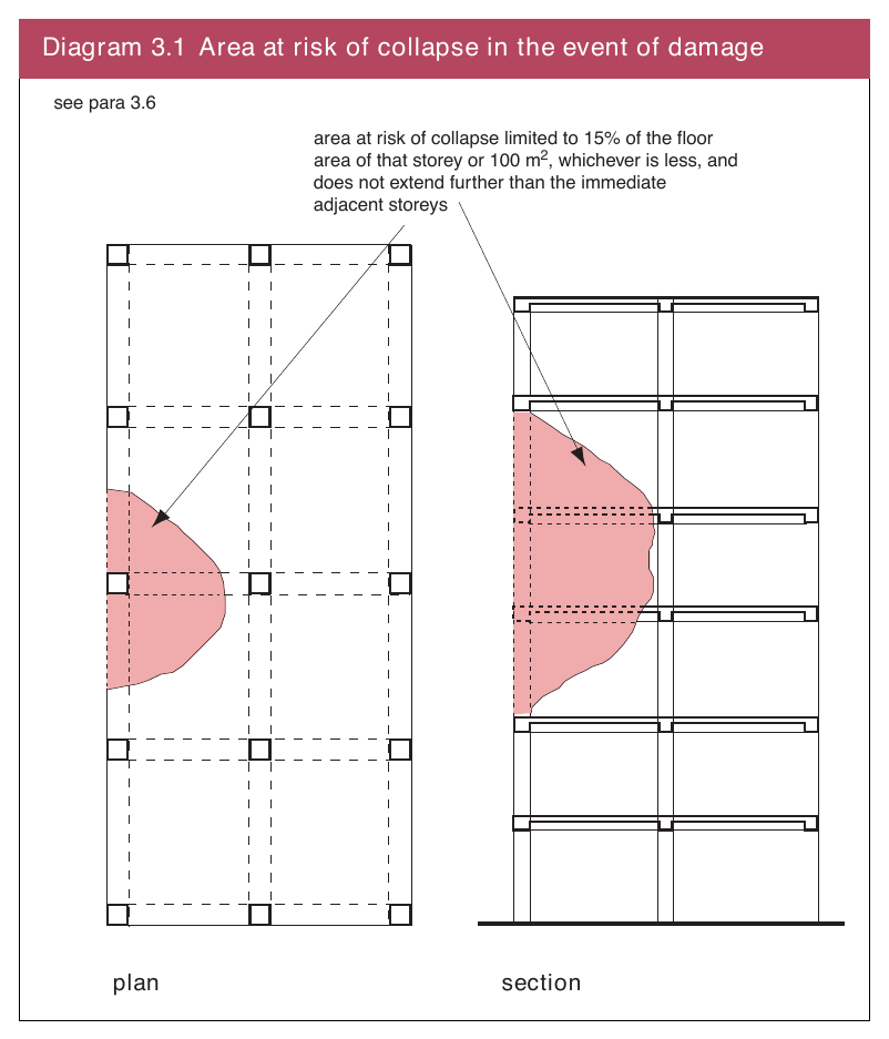
(b)check that upon the notional removal of each supporting column and each beam supporting one or more columns, or any nominal length of loadbearing wall (one at a time in each storey of the building) that the building remains stable and that the area of floor at any storey at risk of collapse does not exceed 15% of the floor area of that storey or 100 m2, whichever is smaller, and does not extend further than the immediate adjacent storeys (see Diagram 3.1).
Where the notional removal of such columns and lengths of walls would result in an extent of damage in excess of the above limit, then any such element should be designed as a “key element” as described in paragraph 3.10.
Class 3 buildings
3.7For Class 3 buildings, a systematic risk assessment of the building should be undertaken taking into account all the normal hazards that may reasonably be foreseen, together with any abnormal hazards.
Critical situations for design should be selected that reflect the conditions that can reasonably be foreseen as possible during the life of the building. The structural form and concept and any protective measures should then be chosen and the detailed design of the structure and its elements undertaken in accordance with the recommendations given in the Codes and Standards given in paragraph 3.8.
Page 20
#Source page 20
Diagram 3.1 Area at risk of collapse in the event of damage
Codes and Standards
3.8Details of the effective horizontal and vertical ties, together with the design approaches for checking the integrity of the building following the notional removal of vertical members and the design of key elements, are available in BS EN 199117.
As an alternative to the above, the Standards referenced below which have been withdrawn by the British Standards Institution, may be used to satisfy the requirements of the building regulations. However, designers will be required to demonstrate appropriate use of withdrawn standards in the circumstances of the building work. Using withdrawn British Standards may continue to be acceptable where it can be demonstrated that design reliability can be achieved —
(a)BS 5628: Part 1;
(b)BS 5950: Part 1;
(c)BS 8110: Part 1; and
(d)BS 8110: Part 2.
Page 21
#Source page 21
Nominal length of loadbearing wall
3.9The nominal length of loadbearing wall construction referred to in paragraph 3.6(b) should be taken as follows —
(a)in the case of a reinforced concrete wall, the distance between lateral supports, subject to a maximum length not exceeding 2.25H;
(b)in the case of an external masonry wall, or timber or steel stud wall, the length measured between vertical lateral supports; and
(c)in the case of an internal masonry wall, or timber or steel stud wall, a length not exceeding 2.25H,
where H is the storey height in metres.
Key elements
3.10A “key element”, as referred to in paragraph 3.6, should be capable of sustaining an accidental design loading of 34 kN/m2 applied in the horizontal and vertical directions (in one direction at a time), to the member and any attached components (e.g. cladding etc.), having regard to the ultimate strength of such components and their connections. Such accidental design loading should be assumed to act simultaneously with one third of all normal characteristic loading (i.e. wind and imposed loading).
Loadbearing wall construction
3.11For the purposes of this Section the term “loadbearing wall construction” includes masonry crosswall construction and walls comprising close centred timber or lightweight steel section studs.
Houses, annexes and small single storey buildings
#Source page 22
Application and presentation
#Source page 23
Section 4 Single family houses, annexes and small single storey buildings
Application and presentation
4.1
This Section applies to a single family house of not more than 3 storeys in height, an annex, and a small single storey building other than a dwelling.
4.2
This section is presented as follows — 4A Basic requirements for stability. 4B Timber floor, ceiling and roof members in a house. 4C Masonry walls. 4D Proportions for masonry chimneys above the roof surface. 4E Foundations of plain concrete.
4A Basic requirements for stability
#Source page 24
General
4A.1 These basic requirements for stability must be used in conjunction with Sections 4B and 4C.
Roofs
Trussed rafter roofs should be braced to the recommendations of BS 5268: Part 3. Where a traditionally framed roof (i.e. using rafters, purlins and ceiling joists) does not have sufficient builtin resistance to instability, for instance from hipped returns, rigid sarking or the like, then bracing equivalent to that recommended in BS 5268: Part 3 should be provided.
Walls
If the roof structure is braced as described above and adequately anchored to the structure beneath, and the walls are designed and restrained in accordance with the requirements of Section 4, no further provision is required to take account of loads due to the effect of wind pressure or suction.
4B Timber floor, ceiling and roof members in a house
#Source page 25
Determination of dimensions of timber members
| 4B.1 | The dimensions of a timber floor, ceiling or roof member may be determined by following either – |
|---|---|
| (a) the guidance given in “Eurocode 5 span tables for solid timber members in floors, ceilings and roofs for dwellings” published by TRADA and available from Chiltern House, Stocking Lane, Hughenden Valley, High Wycombe, Bucks HP14 4ND; or | |
| (b) the guidance given in paragraphs 4B.2 to 4B.15. | |
| Generally | |
| 4B.2 | The stability requirements in paragraph 4A.1 should be complied with when using this Section. |
| 4B.3 | The dimensions of a timber member may be determined by this Section where – |
| (a) the dead and imposed loads to be sustained by the floor, ceiling or roof of which the member forms part, do not exceed the values given in the appropriate diagrams and tables; | |
| (b) the species and grade of timber for the strength class to which the table relates is either – | |
| (i) | as given in Table 4B.1 for more common species; or |
| (ii) as given in the more comprehensive tables of BS 5268: Part 2; | |
| (c) the timber is service class 1 or 2 and is clearly marked “Dry” or “KD” (kiln dried); and | |
| (d) floorboarding complying with BS 1297 is used. | |
| 4B.4 | Strength classes, species, grades and species combinations referred to in this Section are as defined in BS 5268: Part 2. |
| 4B.5 | Cross sectional dimensions given in the tables to this Section are applicable to either basic sawn or regularised sizes as defined in BS EN 1313 1. Reference should be made to the accompanying notes to the tables to determine whether sawn or regularised sizes apply. The tables do not apply where dimensions have been reduced by planing. For timber of North American origin the tables apply only as indicated to surface sizes unless the timber has been resawn to BS EN 1313 1 requirements. |
| 4B.6 | Notches and holes in simply supported floor and roof joists should be within the limits shown in Diagram 4B.1. No notches or holes should be cut in roof rafters, other than at supports where the rafter may be birdsmouthed to a depth not exceeding 0.33 times the rafter depth. |
| 4B.7 | Bearing areas and workmanship should comply with the relevant requirements of BS 5268: Part 2 and to the lateral restraint provisions given in paragraphs 4C.21 to 4C.24. |
Page 26
#Source page 26
Diagram 4B.1 Limitations for notches and holes in floor and roof joists
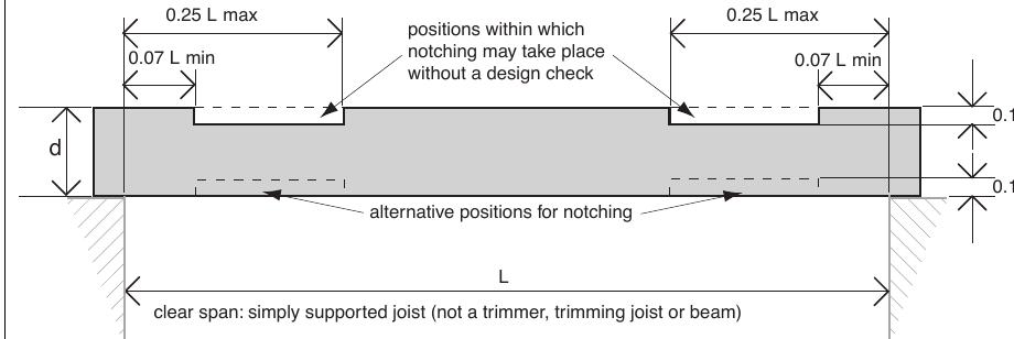
see para 4B.6
0.125d max
0.125d max
a)limits for notching
| 0.2 L max ● ● | ●● | |||
|---|---|---|---|---|
| ● ● | ||||
| 0.15 d max● ● ● 0.15 d max ● | ||||
| ● ● | ||||
| ● ● ● ● | 0.1 L ● ● | ● ● min | ● alternative position for notching | |
| ● ● |
Note: This alternative notching may occur at both ends without a design check d 250 mm
b)alternative limits for notching
holes not exceeding 0.25 d diameter may be positioned on the centre line between 0.25 L and 0.4 L from a support without a design check
| ● | ● ● d | ● 250 mm | ● ● | ||||||
|---|---|---|---|---|---|---|---|---|---|
| ● | ● ● | ● ● | |||||||
| ● ● ● ● | not closer than 3 x diameter ● | ● ● | L | ● ● | no hole to be closer than 100 mm to any notch (and vice-versa) ● | ● ● ● ● ● | |||
| ● ● ● ● ● ● | |||||||||
| ● ● |
c)limits for drilling
end of joists, trimmers, etc. supported by a joist hanger should be shaped to house the thickness and profile of the joist hanger chosen
means not greater than
d)end trimming
Species
#Source page 27
Table 4B.1 Stress grade/species combinations which meet the strength classes C16 and C24
Species
All species listed in this Table, machine graded to BS EN 140811 and marked accordingly
Imported redwood or whitewood visually graded to BS 4978
British grown visually graded to BS 4978
Canadian visually graded to BS 4978
Canadian graded to NLGA
Canadian graded to MSR Standard
USA visually graded to BS 4978
USA graded to NGRDL
USA graded to MSR Standard
Notes: Douglas fir Larch Pine Spruce Douglas firlarch Hemfir Sprucepinefir Sitka spruce
Douglas firlarch
Hemfir
Sprucepinefir
Sitka spruce
Douglas firlarch Hemfir Sprucepinefir Douglas firlarch Hemfir Southern pine Sprucepinefir Western white wood
Douglas firlarch
Hemfir
Sprucepinefir
Western white wood
Southern pine
Douglas firlarch Hemfir Southern pine Sprucepinefir
Graded to meet strength class C16
Machine graded to C16
GS
SS SS SS SS GS GS GS SS Joist and Plank No. 1 and No. 2 Structural L.F. No. 1 and No. 2 Joist and Plank No. 1 and No. 2 Structural L.F. No. 1 and No. 2 Joist and Plank No. 1 and No. 2 Structural L.F. No. 1 and No. 2 Joist and Plank Select Structural L.F. Machine stressrated, 1 450f 1.3E Machine stressrated, 1 450f 1.3E Machine stressrated, 1 450f 1.3E GS GS GS GS SS Joist and Plank No. 1 and No. 2 Structural L.F. No. 1 and No. 2 Joist and Plank No. 1 and No. 2 Structural L.F. No. 1 and No. 2 Joist and Plank No. 1 and No. 2 Structural L.F. No. 1 and No. 2 Joist and Plank Select Structural L.F. Select Joist and Plank No. 3 Stud grade Machine stressrated, 1 450f 1.3E
Machine stressrated, 1 450f 1.3E
Machine stressrated, 1 450f 1.3E
Machine stressrated, 1 450f 1.3E
Graded to meet strength class C24
Machine graded to C24
SS
SS SS SS
Joist and Plank Select Structural L.F. Joist and Plank Select Structural L.F. Joist and Plank Select
Machine stressrated, 1 800f 1.6E Machine stressrated, 1 800f 1.6E Machine stressrated, 1 800f 1.6E SS SS SS SS
Joist and Plank Select Structural L.F. Select
Joist and Plank Select Structural L.F. Select
Joist and Plank Select Structural L.F. Select
Joist and Plank Select
Machine stressrated, 1 800f 1.6E
Machine stressrated, 1 800f 1.6E
Machine stressrated, 1 800f 1.6E
Machine stressrated, 1 800f 1.6E
1.Where one stress grade is tabulated, any stronger stress grade of the same species also meets the strength class
2.BS 5268: Part 2 contains a larger selection of stress – grade/species combinations which meet C16 and C24 strength class
Spans, sizes and spacings for timber members
#Source page 28
4B.8 Table 4B.3 sets out a schedule of tables, which are preceded by notes and diagrams, that give spans, sizes and spacings for certain timber floor, ceiling and roof members.
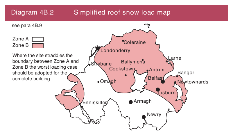
4B.9 Tables 4B.11 to 4B.44 give the sizes of certain roof members for imposed loads of 0.75 kN/m2 and 1.00 kN/m2. The loading applicable at a particular site depends on the elevation of that site above sea level and the zone in which it is situated. (See Table 4B.2 and Diagram 4B.2.)
The tables for the pitched roof timbers are only applicable to a building where no access is provided to the roof, other than that necessary for cleaning and maintenance, which has –
(a)a roof area not greater than 200 m2 in plan; or
(b)a width not greater than 10 m and a pitched roof with no parapet,
provided that there are no other buildings within 1.5 m of its perimeter, and provided the roof configuration also meets one of the following conditions –
(i)the roof has no abrupt changes of height greater than 1 m, at which a drift of snow could occur; or
(ii)the area of a lower part of the roof, on which a drift of snow could form, is not greater than 35 m2.
Any building that does not fall within the criteria set out above is outside the scope of this Technical Booklet.
| Table 4B.2 Simplified imposed roof loads | ||
|---|---|---|
| Altitude of site above sea level (m) | Zone A (kN/m²) | Zone B (kN/m²) |
| from 0 to 100 | 0.75 | 0.75 |
| more than 100 but not more than 150 | 0.75 | 0.75 |
| more than 150 but not more than 200 | 0.75 | 1.00 |
| more than 200 but not more than 250 | 1.00 | 1.00 |
| more than 250 but not more than 300 | 1.00 | – |
Diagram 4B.2 Simplified roof snow load map
Page 29
#Source page 29
| Table 4B.3 Schedule of Tables relating to timber members | ||||
|---|---|---|---|---|
| Construction | Timber members | Imposed loading kN/m ² | Table number | |
| C16 | C24 | |||
| Floors | joists | 1.50 | 4B.5 | 4B.6 |
| Ceilings | joists | 0.25 | 4B.7 | 4B.9 |
| binders | 0.25 | 4B.8 | 4B.10 | |
| Pitched roofs more than 15o but not more than 22.5o | rafters | 0.75 | 4B.11 | 4B.13 |
| 1.00 | 4B.15 | 4B.17 | ||
| purlins | 0.75 | 4B.12 | 4B.14 | |
| 1.00 | 4B.16 | 4B.18 | ||
| Pitched roofs more than 22.5o but not more than 30o | rafters | 0.75 | 4B.19 | 4B.21 |
| 1.00 | 4B.23 | 4B.25 | ||
| purlins | 0.75 | 4B.20 | 4B.22 | |
| 1.00 | 4B.24 | 4B.26 | ||
| Pitched roofs more than 30o but not more than 45o | rafters | 0.75 | 4B.27 | 4B.29 |
| 1.00 | 4B.31 | 4B.33 | ||
| purlins | 0.75 | 4B.28 | 4B.30 | |
| 1.00 | 4B.32 | 4B.34 | ||
| Flat roofs access for cleaning and maintenance only | joists | 0.75 | 4B.35 | 4B.36 |
| 1.00 | 4B.37 | 4B.38 | ||
| Flat roofs with access allowed | joists | 1.50 | 4B.39 | 4B.40 |
| Sheeted or decked roofs more than 10o but not more than 35o | purlins | 0.75 | 4B.41 | 4B.42 |
| 1.00 | 4B.43 | 4B.44 | ||
| Notes: 1. The strength class given in this Table assumes that the species and grades of timber to be used are those described in Table 4B.1. 2. These Tables do not apply to trussed rafted roofs. |
4B.10 Floor joists spanning in excess of 2.5 m should be strutted by one or more rows of solid or herringbone strutting in accordance with Table 4B.4. Solid strutting should be at least 38 mm timber thickness extending at least 0.75 times the depth of the joists. Herringbone strutting should be of at least 38 mm x 38 mm timber size but should not be used where the distance between joists is greater than 3 times the depth of the joists.
| Table 4B.4 Strutting to joists | |
|---|---|
| Joist span | No. of rows and position of strutting |
| Not greater than 2.5 m | None |
| Greater than 2.5 m but not greater than 4.5 m | 1 at midspan |
| greater than 4.5 m | 2 at one third span positions |
Floor joists
#Source page 30
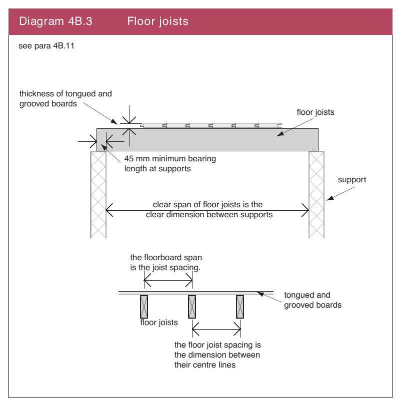
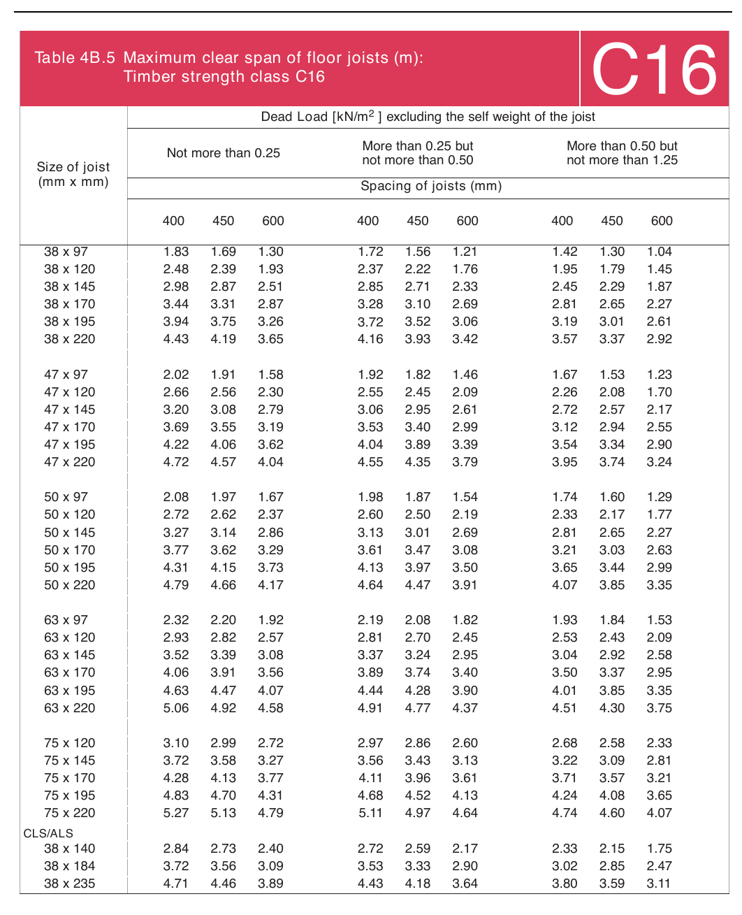
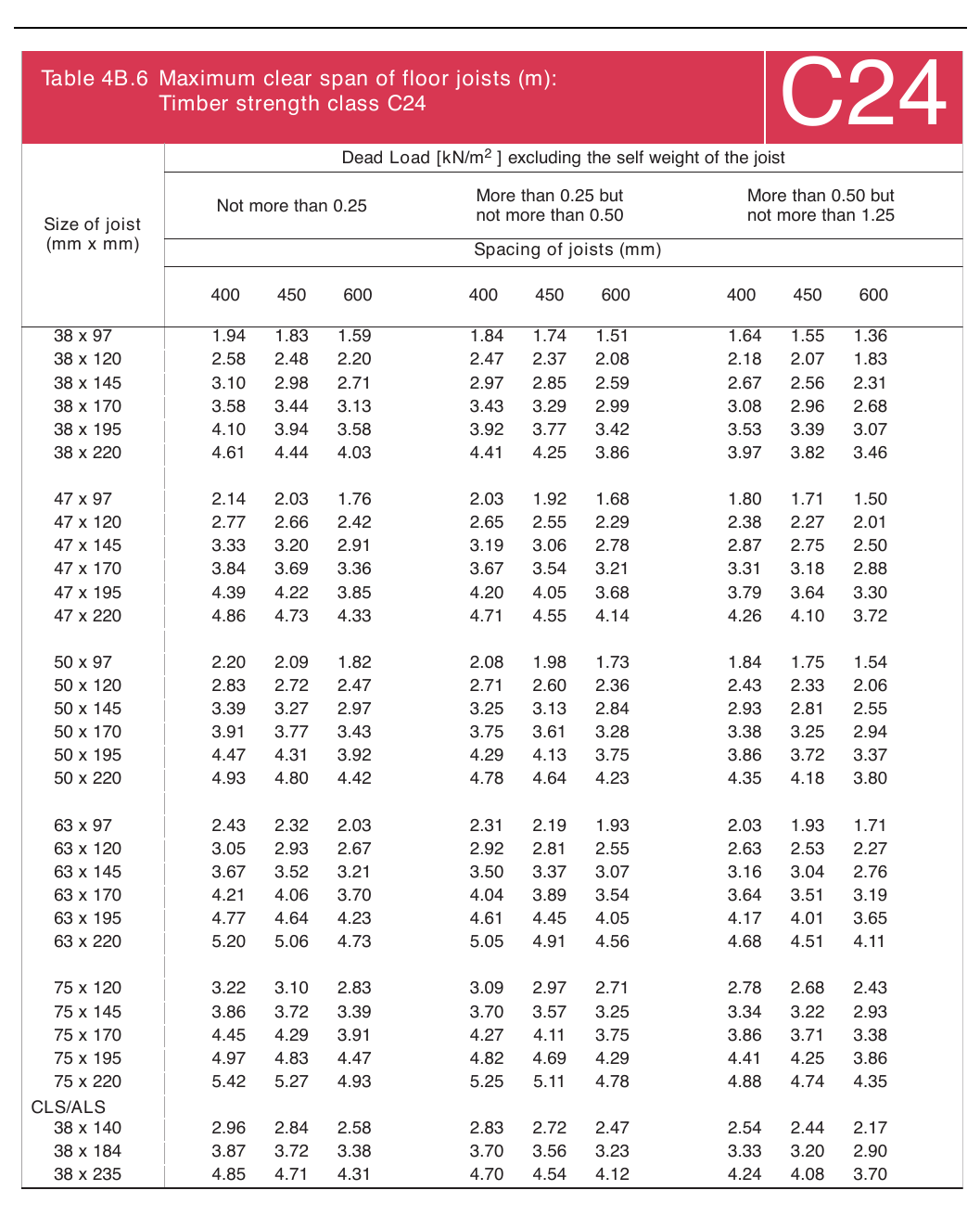
4B.11 Tables 4B.5 and 4B.6 give the maximum clear span for floor joists using timber strength class C16 and C24 that will support the dead loads specified and a maximum imposed floor loading of 1.5 kN/m2. Partition loads are not allowed for in Tables 4B.5 and 4B.6.
Softwood tongued and grooved floorboards 16 mm thick will safely support this floor loading if the spacing of the joists is not greater than 500 mm. Floorboarding 19 mm thick is required if the spacing of the floor joists is greater than 500 mm but not greater than 600 mm.
These tables can be used when a bath is to be installed provided the joists directly supporting the bath are doubledup. There is no allowance made for the weight of partitions.
The section sizes are either sawn across the timber thickness in accordance with tolerance class 1 of BS EN 336 and processed in accordance with tolerance class 2 of BS EN 336 across the timber width (joist depth), or are Canadian Lumber Standards/ American Lumber Standards (CLS/ALS) processed sizes in accordance with tolerance class 2, to provide level surfaces for ease of ceiling lining and the fixing of structural decking.
If the end of a joist is supported on masonry, the end bearing should be increased from the 45 mm shown in Diagram 4B.3 to not less than 90 mm to provide restraint to the masonry wall.
Diagram 4B.3 Floor joists
Page 31
#Source page 31
Table 4B.5 Maximum clear span of floor joists (m):
Page 32
#Source page 32
Table 4B.6 Maximum clear span of floor joists (m):
Ceiling joists and binders supporting ceiling joists
#Source page 33
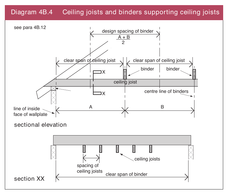
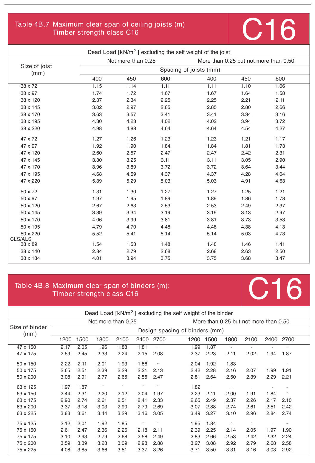
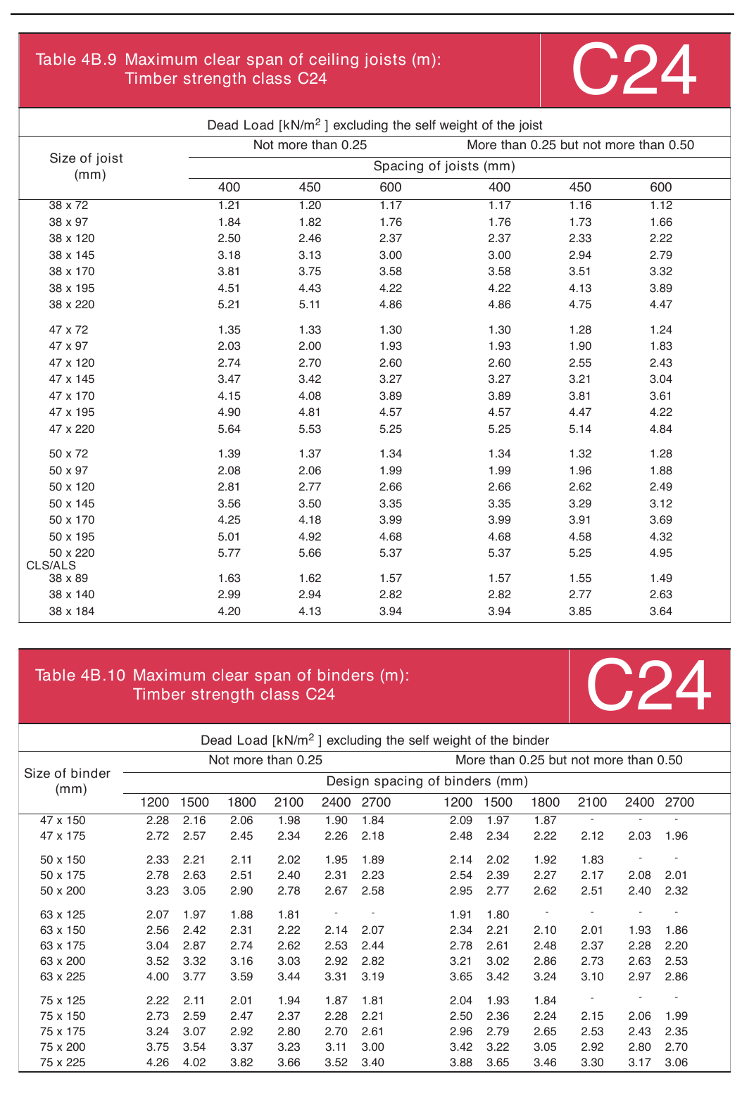
4B.12 Tables 4B.7 to 4B.10 give the maximum clear span of a ceiling joist and the timber binder that provides support to the ceiling joists using timber strength class C16 and C24. See also Diagram 4B.4.
The sizes, spacings and spans given will safely support the dead loads stated in the tables, together with a maximum imposed load of 0.25 kN/m2 and a concentrated load of 0.9 kN acting together.
In calculating the ceiling joist sizes for these tables no account has been taken of trimming around items such as flues or the additional load of such things as water tanks.
Notching or drilling of a binder or ceiling joist should not be carried out unless justified by specialist calculation.
In the tables for ceiling joists the permissible clear spans are for ceiling joists simply supported between binders or a binder and the wallplate. However, in the tables for binders, the permissible clear spans are based on the assumption that the ceiling joists can be continuous.
The section sizes are either sawn across the timber thickness in accordance with tolerance class 1 of BS EN 336 and processed in accordance with tolerance class 2 of BS EN 336 across the timber width (joist depth), or are CLS/ALS processed sizes in accordance with tolerance class 2, to provide level surfaces for ease of ceiling lining and the fixing of structural decking.
The size of ceiling joists and binders are limited generally to those where the depthtothickness ratio is not greater than 4 unless lateral support is provided in accordance with BS 5268: Part 2.
Diagram 4B.4 Ceiling joists and binders supporting ceiling joists
Page 34
#Source page 34
Table 4B.7 Maximum clear span of ceiling joists (m)
Page 35
#Source page 35
Table 4B.9 Maximum clear span of ceiling joists (m):
Rafters and purlins supporting rafters
#Source page 36
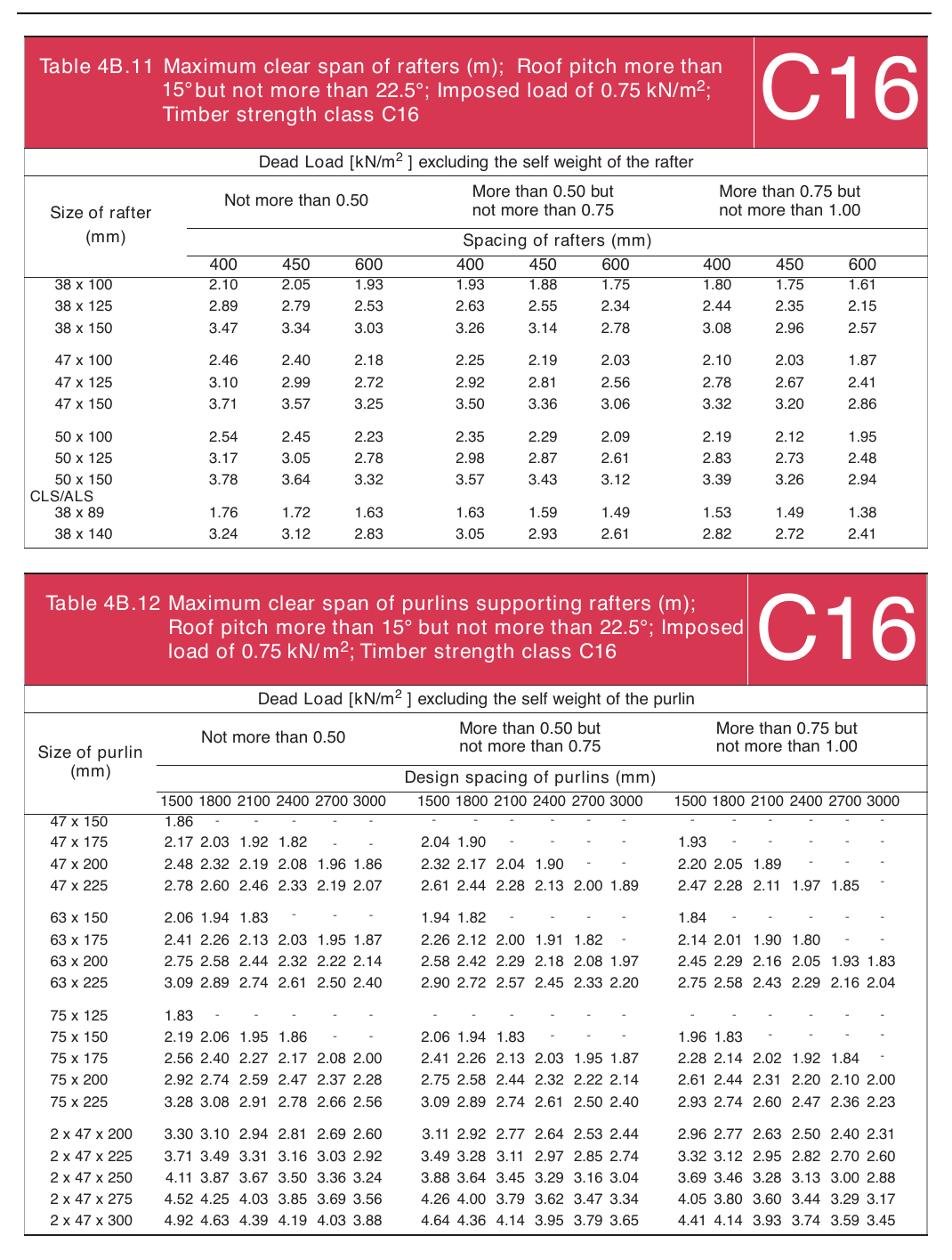
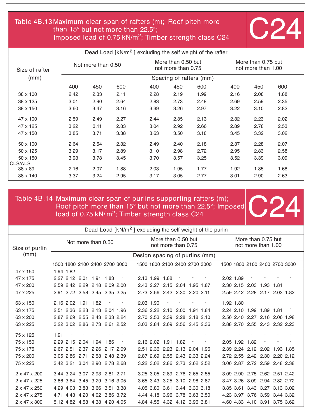
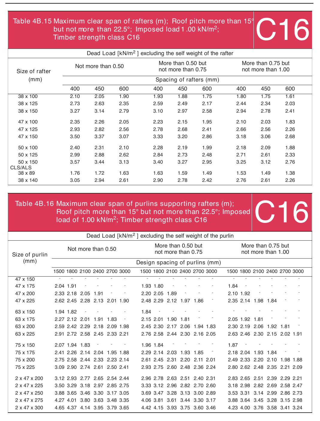
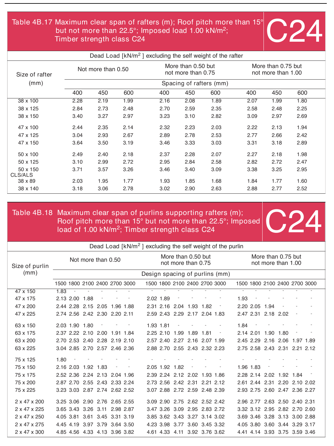
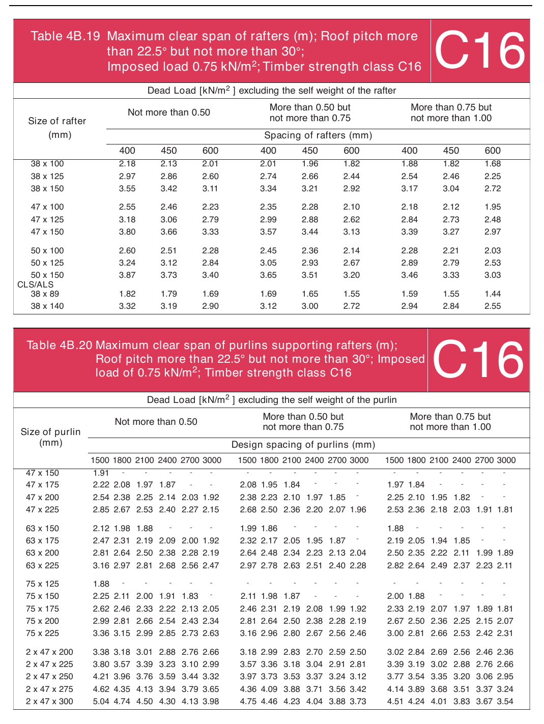
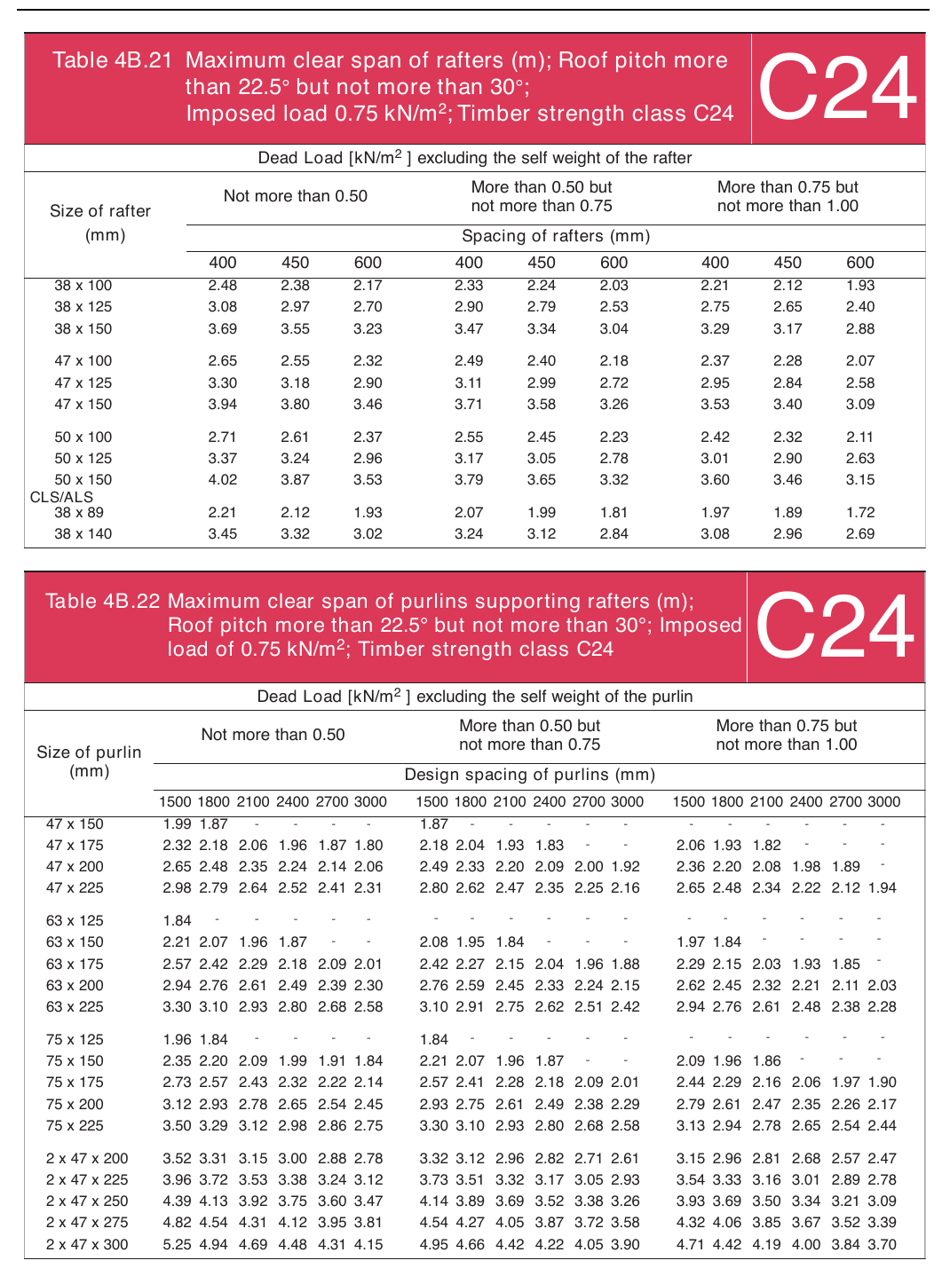
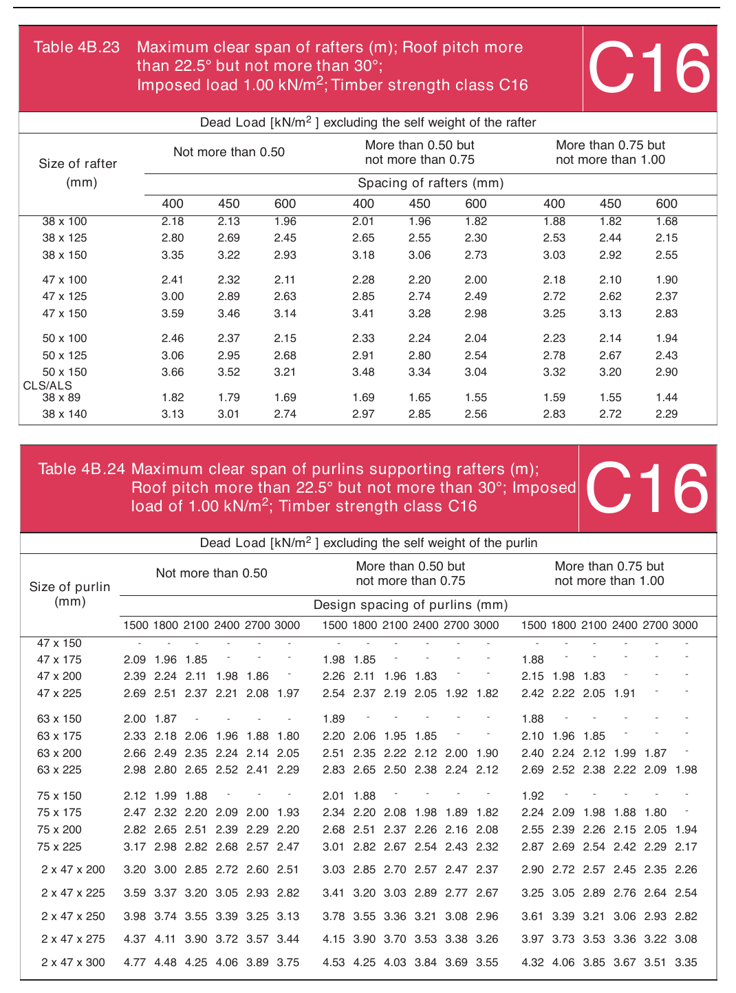
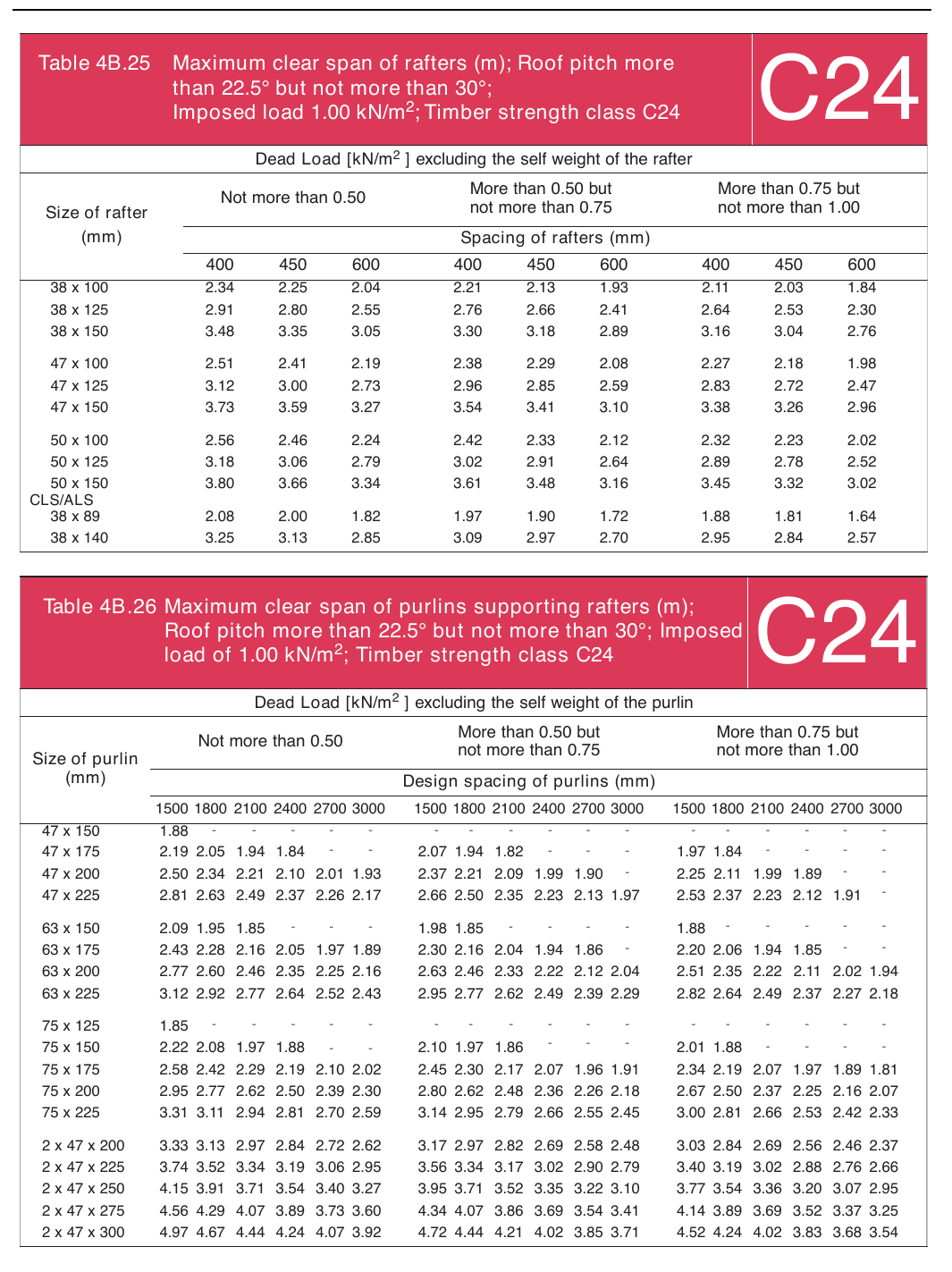
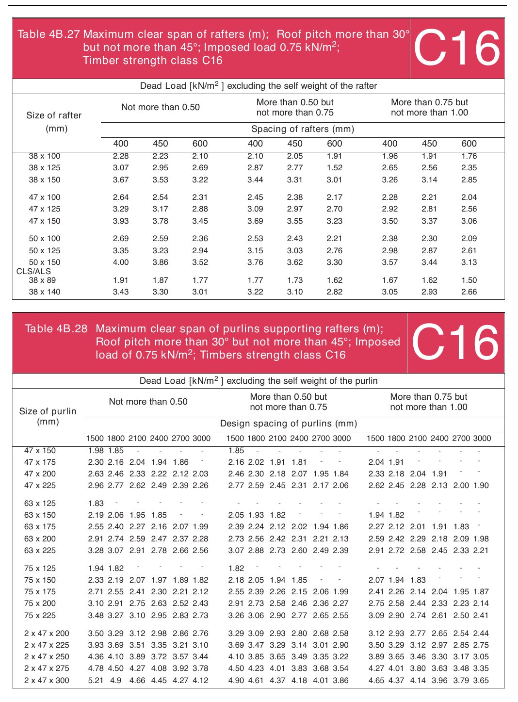
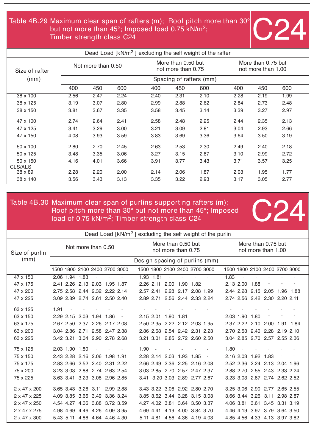
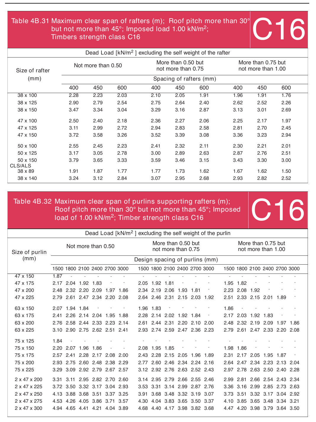
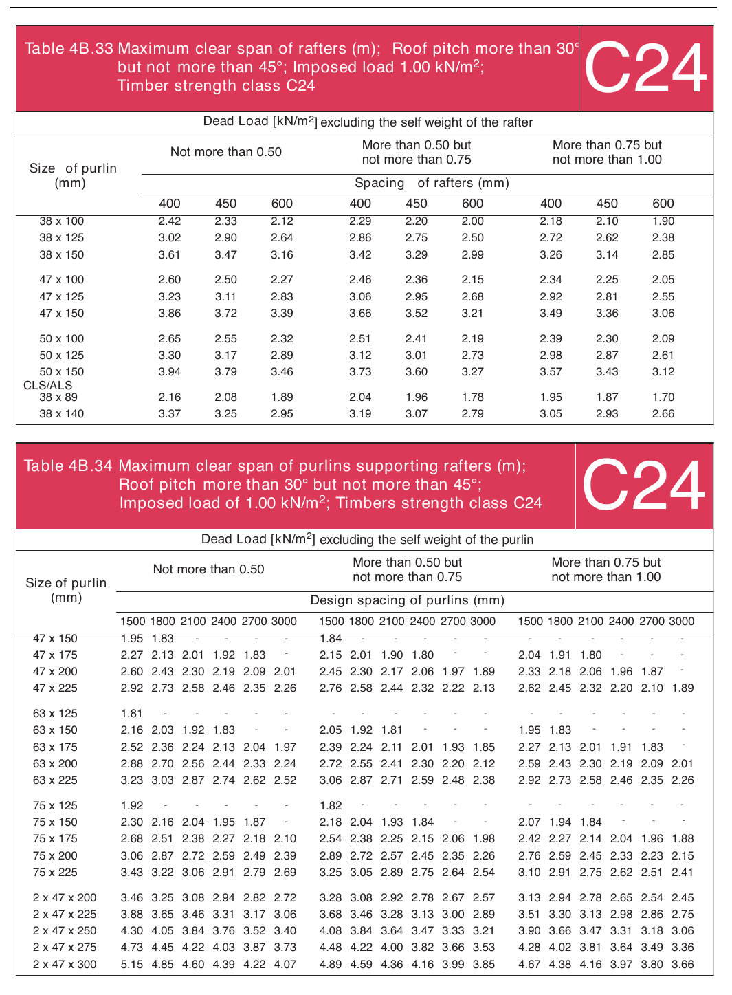
4B.13 Tables 4B.11 to 4B.34 give the maximum clear span of common or jack rafters and the purlins that provide support to the common or jack rafters using timber strength class C16 and C24.
The sizes, spacings and spans given will safely support the dead loads stated in the tables, together with a maximum imposed load of 0.75 kN/m2 or 1.00 kN/m2 or a concentrated load of 0.9 kN.
The tables are presented in sets to cover a range of roof pitch from 15o to 45o for each load combination and strength class of timber.
In calculating the rafter sizes for these tables no account has been taken of permitted reduction to the imposed loads for a pitch greater than 30o, as recommended in BS 6399: Part 3. This is because the members have been sized assuming a pitch of 30o as being the most onerous for the pitch range 30o to 45o.
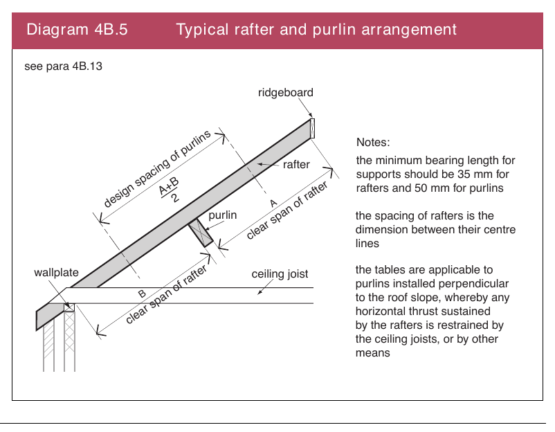
When the dimensions A and B in Diagram 4B.5 are not equal the rafter should be sized for the greater dimension. Where the purlin is continuous over an intermediate support and the spans are not equal the purlin should be sized for the longest span.
In the tables for rafters, the permissible clear spans are for rafters simply supported between a purlin and wallplate or between a purlin and the ridgeboard. However, in the tables for purlins, the permissible clear spans are based on the assumption that the rafters are to be continuous.
Notching or drilling of a rafter or purlin should not be carried out unless justified by a specialist calculation. This does not apply to the birdsmouthing of a rafter to a depth not greater than one third of the depth of the rafter.
The section sizes given in the tables are either sawn in accordance with tolerance class 1 of BS EN 336, or are CLS/ALS processed sizes in accordance with tolerance class 2 of BS EN 336.
Diagram 4B.5 Typical rafter and purlin arrangement
Page 37
#Source page 37
Table 4B.11 Maximum clear span of rafters (m); Roof pitch more than
Page 38
#Source page 38
Table 4B.13 Maximum clear span of rafters (m); Roof pitch more
Page 39
#Source page 39
Table 4B.15 Maximum clear span of rafters (m); Roof pitch more than 15°
Page 40
#Source page 40
Table 4B.17 Maximum clear span of rafters (m); Roof pitch more than 15°
Page 41
#Source page 41
Table 4B.19 Maximum clear span of rafters (m); Roof pitch more
Page 42
#Source page 42
Table 4B.21 Maximum clear span of rafters (m); Roof pitch more
Page 43
#Source page 43
Table 4B.23 Maximum clear span of rafters (m); Roof pitch more
Page 44
#Source page 44
Table 4B.25 Maximum clear span of rafters (m); Roof pitch more
Page 45
#Source page 45
Table 4B.27 Maximum clear span of rafters (m); m Roof pitch ore than 30°
Page 46
#Source page 46
Table 4B.29 Maximum clear span of rafters (m); Roof pitch more than 30°
Page 47
#Source page 47
Table 4B.31 Maximum clear span of rafters (m); Roof pitch more than 30°
Page 48
#Source page 48
Table 4B.33 Maximum clear span of rafters (m); Roof pitch more than 30°
Flat roof joists
#Source page 49
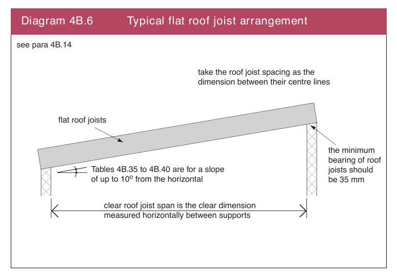
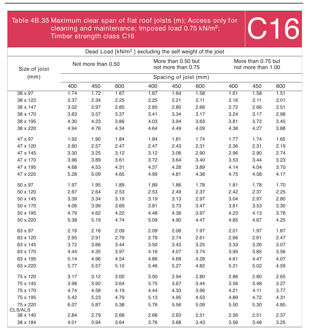
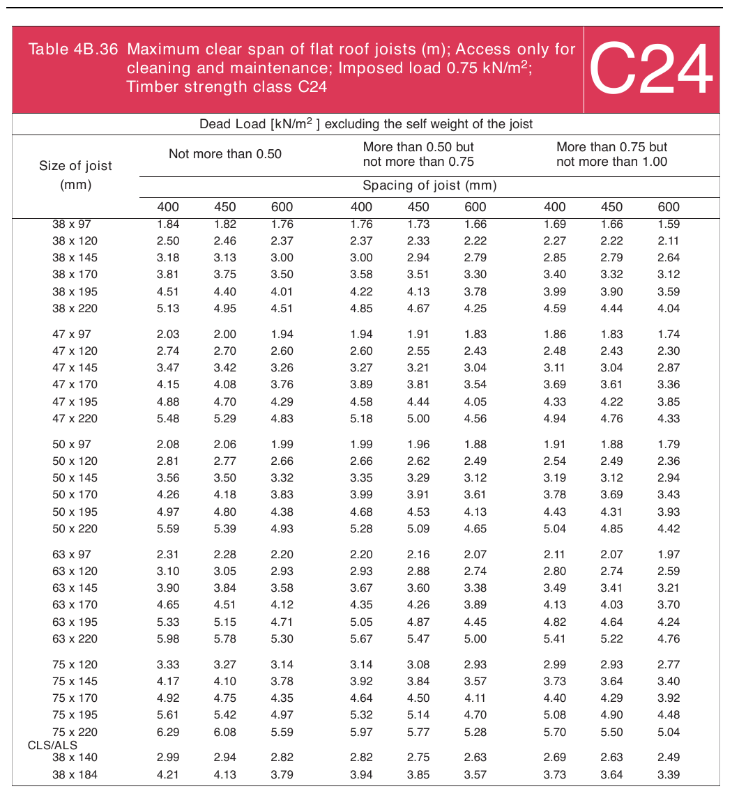
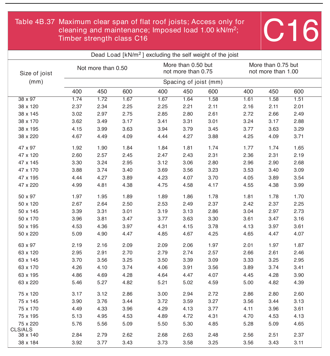
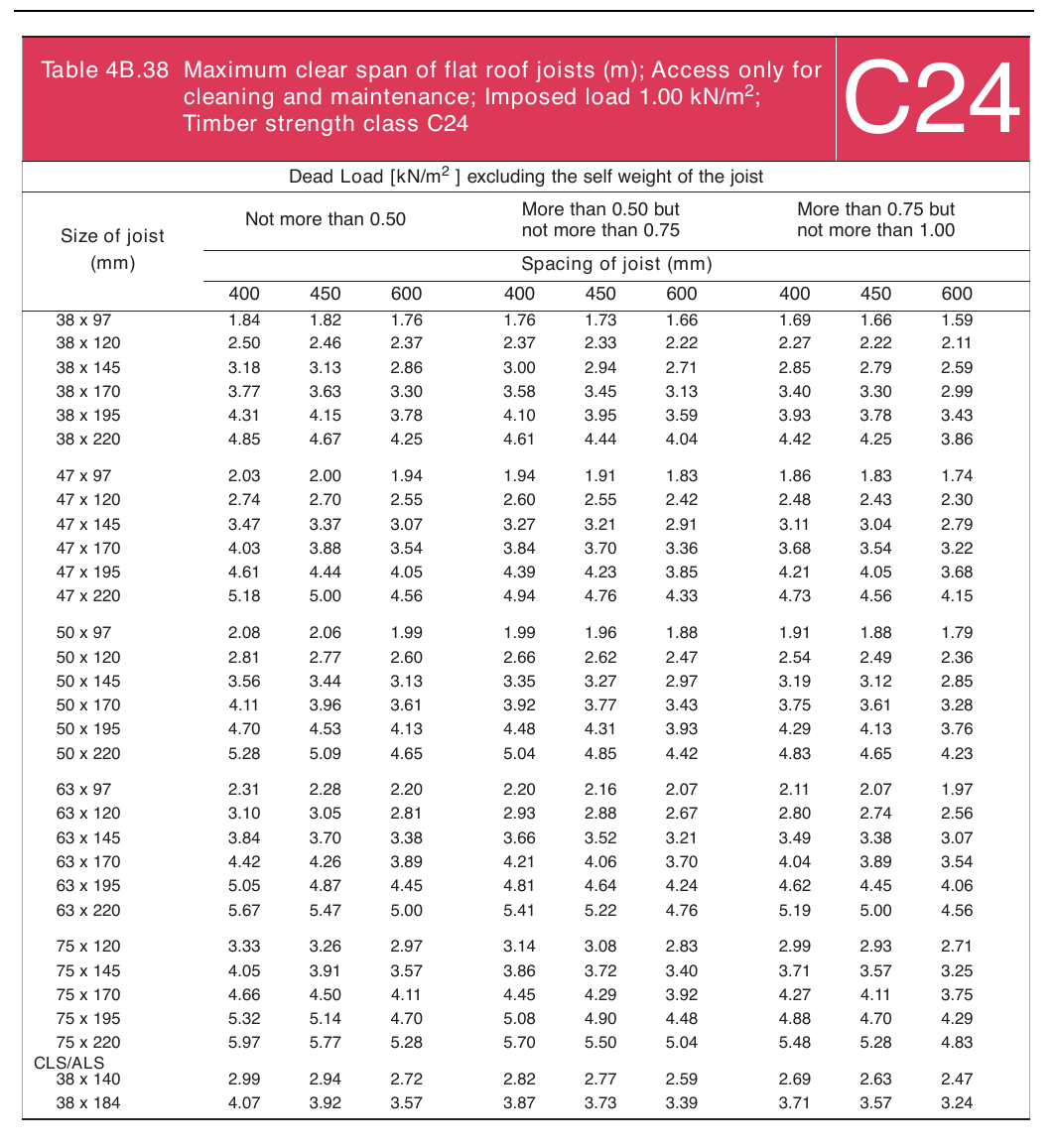
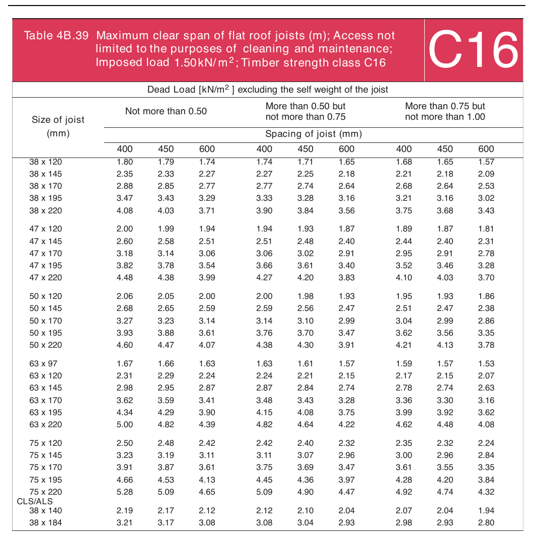
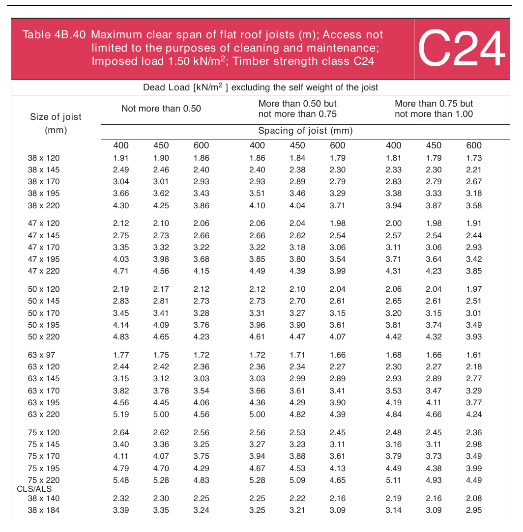
4B.14 Tables 4B.35 to 4B.38 give the maximum clear span of joists for a flat roof using timber strength class C16 and C24.
The sizes, spacings and spans given will safely support the dead loads stated in the tables, together with a maximum imposed load of 0.75 kN/m2 or 1.00 kN/m2 or a concentrated load of 0.9 kN provided access is limited for the purpose of cleaning and maintenance only.
Tables 4B.39 and 4B.40 are also given for a flat roof where the access is not limited to the purposes of cleaning and maintenance only and in these tables the imposed load is 1.5 kN/m2 or a concentrated point load of 1.8 kN.
The section sizes are either sawn across the timber thickness in accordance with tolerance class 1 of BS EN 336 and processed in accordance with tolerance class 2 of BS EN 336 across the timber width (joist depth), or are CLS/ALS processed sizes in accordance with tolerance class 2, to provide level surfaces for ease of ceiling lining and the fixing of structural decking.
See Diagram 4B.6.
Diagram 4B.6 Typical flat roof joist arrangement
Page 50
#Source page 50
Table 4B.35 Maximum clear span of flat roof joists (m); Access f only or
Page 51
#Source page 51
Table 4B.36 Maximum clear span of flat roof joists (m); Access only for
Page 52
#Source page 52
Table 4B.37 Maximum clear span of flat roof joists; Access only for
Page 53
#Source page 53
Table 4B.38 Maximum clear span of flat roof joists (m); Access only for
Page 54
#Source page 54
Table 4B.39 Maximum clear span of flat roof joists (m); Access not
Page 55
#Source page 55
Table 4B.40 Maximum clear span of flat roof joists (m); Access not
Purlins supporting decking or sheeting
#Source page 56
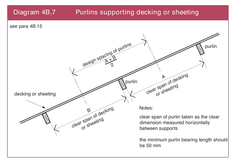
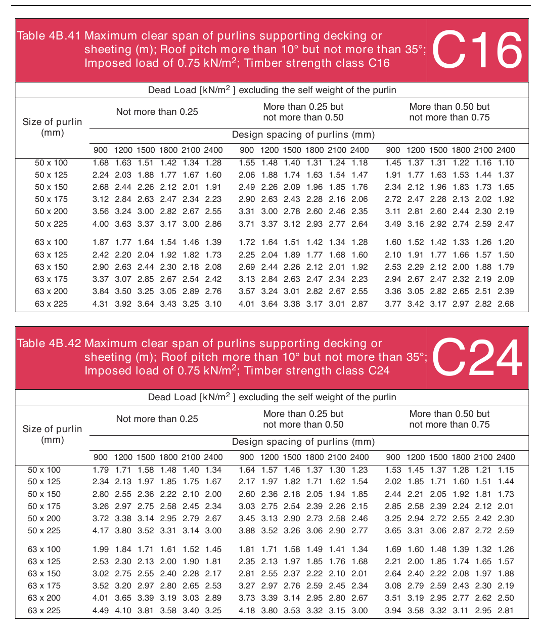
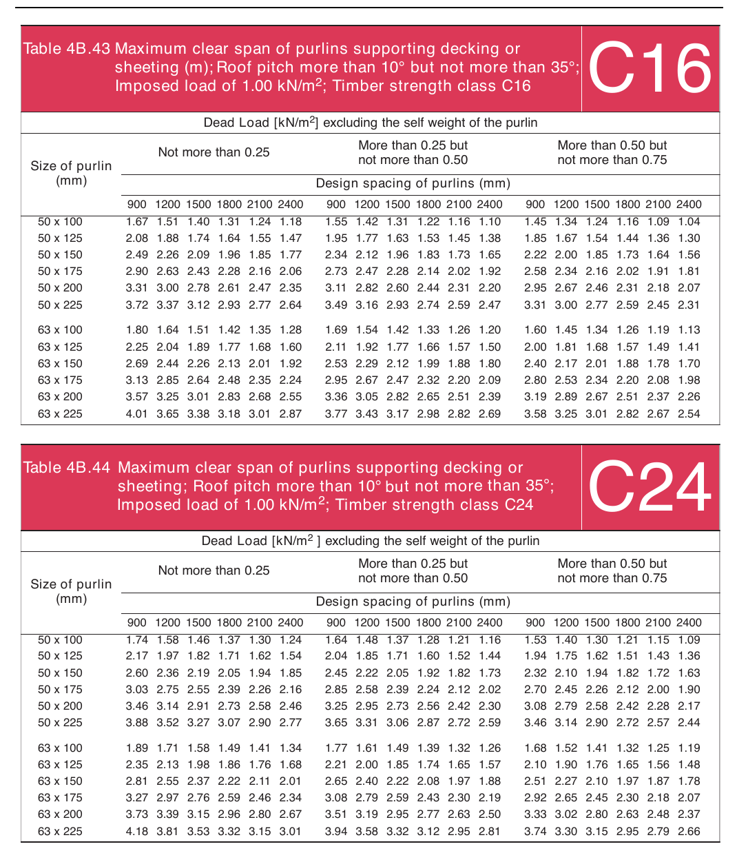
4B.15 Tables 4B.41 to 4B.44 give the maximum clear span of purlins supporting decking or sheeting on roofs that have a pitch greater than 10o but not greater than 35o. The timber strength class used in the tables is C16 and C24.
The sizes, spacings and spans given will safely support the dead loads stated in the tables, together with a maximum imposed load of 0.75 kN/m2 or 1.00 kN/m2, measured on plan, or a concentrated load of 0.9 kN. It is assumed in the tables that access is limited for the purpose of cleaning and maintenance only.
BS 6399: Part 3, permits a reduction in imposed roof loading for a pitch over 30°. This reduction has be noten used in the tables because the tabulated spans are based on a pitch of 10° as giving the most onerous case for the range of spans between 10° and 35°.
The section sizes given in the tables are either sawn in accordance with tolerance class 1 of BS EN 336, or are CLS/ALS processed sizes in accordance with tolerance class 2 of BS EN 336.
The tabulated purlin sizes are designed to resist only the load component perpendicular to the roof pitch with purlins installed normal to the roof pitch. Designers should ensure that the roof construction can satisfactorily accommodate the component of load parallel to the roof pitch.
Notching or drilling of the purlins should not be carried out unless justified by specialist calculation.
See Diagram 4B.7.
Diagram 4B.7 Purlins supporting decking or sheeting
Page 57
#Source page 57
Table 4B.41 Maximum clear span of purlins supporting decking or
Page 58
#Source page 58
Table 4B.43 Maximum clear span of purlins supporting decking or
4C Masonry walls. Part 1 Masonry walls for houses
#Source page 59
General
Application
4C.1 This Part of the Section applies to a single family house that is not more than 3 storeys in height. The walls considered are as follows –
(a)external walls;
(b)internal loadbearing walls;
(c)compartment walls; and
(d)separating walls,
provided they extend to the full storey height.
Exceptions
4C.2 External walls sized using this Section are not necessarily suitable for the support of building mounted wind turbines. Specialist advice from a suitably qualified person must be obtained to confirm the suitability of any wall subjected to such loading.
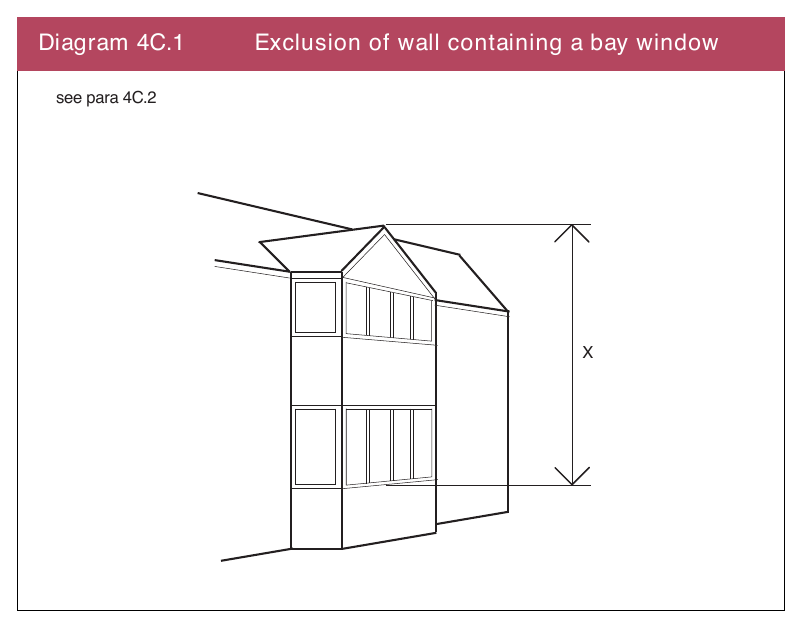
This Part does not apply to any portion of an external wall which is constructed as a bay for, or as a gable over, a bay window above ground floor cill level indicated as X in Diagram 4C.1.
Diagram 4C.1 Exclusion of wall containing a bay window
Page 60
#Source page 60
The use of this Part
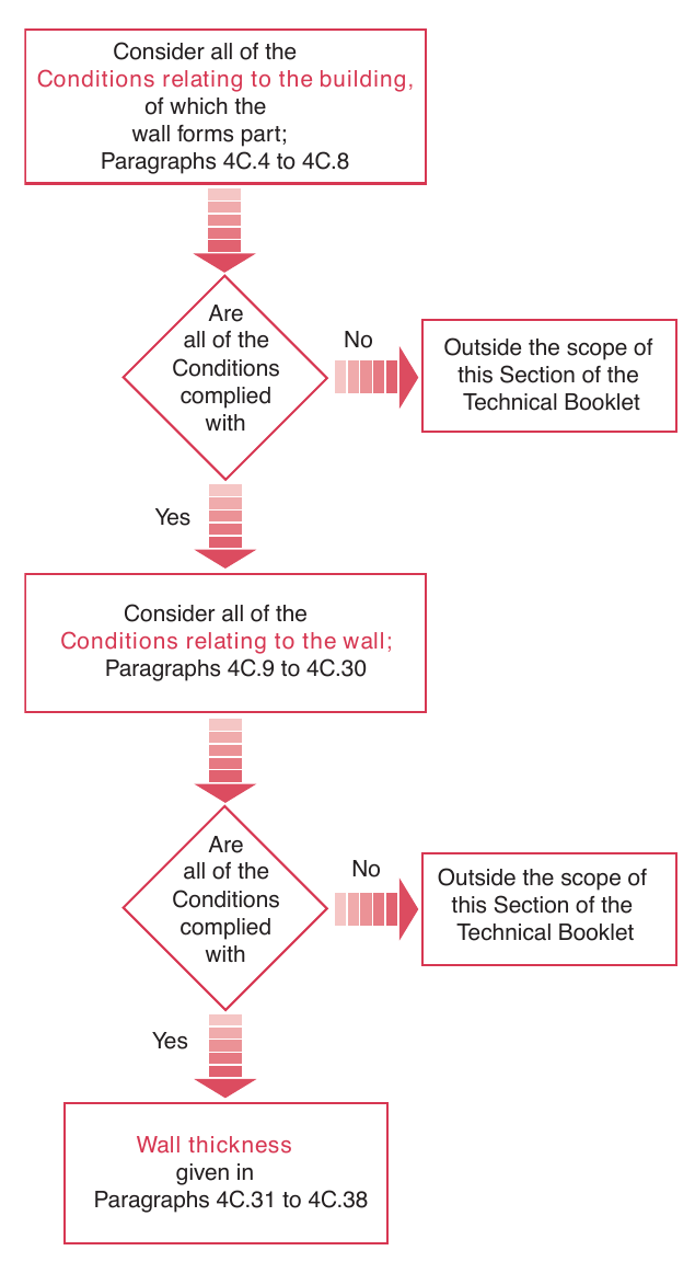
4C.3 When using this Part of the Section the stability requirements in paragraph 4B.1 applies and the following procedure should be followed –
General conditions
#Source page 61
Conditions relating to the building
General conditions
Building proportions
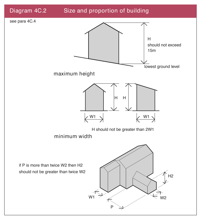
4C.4 The building proportions should be within the following parameters –
(a)the maximum height of the building measured from the lowest finished ground level adjoining the building to the highest point of any wall or roof should be not greater than 15 m;
(b)the height of the building H should not exceed twice the least width of the building W1; and
(c)the height of a wing H2 should not exceed twice the least width of the wing W2 when the projection P exceeds twice the width W2 (see Diagram 4C.2).
Diagram 4C.2 Size and proportion of building
Page 62
#Source page 62
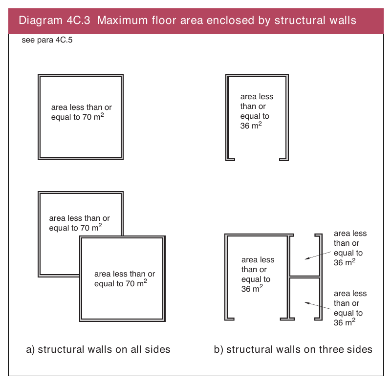
4C.5 For stability, the maximum floor area enclosed by structural walls complying with the provisions of paragraphs 4C.9 to 4C.30 should be –
(a)70 m2 where there are structural walls on all four sides; and
(b)36 m2 where there are only structural walls on three sides. See Diagram 4C.3.
Diagram 4C.3 Maximum floor area enclosed by structural walls
Maximum imposed loads on roofs, floors and ceilings
4C.6 The maximum imposed loads on each element of the building should not exceed those given in Table 4C.1.
| Table 4C.1 Simplifed maximum imposed loads | |
|---|---|
| Element | Loading |
| Roof | distributed load of 1.5 kN/m² for spans not greater than 6m, and 1.00 kN/m² for spans greater than 6m but not greater than 12m |
| Floors | distributed load of 2.0 kN/m² |
| Ceilings | distributed load of 0.25 kN/m² together with a concentrated load of 0.9 kN |
Page 63
#Source page 63
Maximum permitted height of buildings
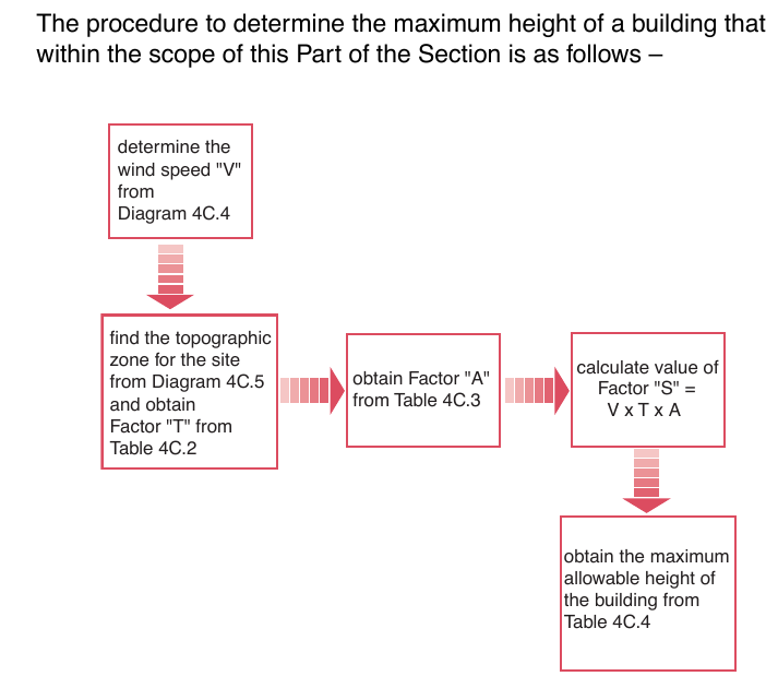
4C.7 A simplified design methodology has been developed for the determination of the maximum height of building for which this Part can be used. The maximum height is dependant on a range of factors as follows –
(a)the wind speed as given in Diagram 4C.4;
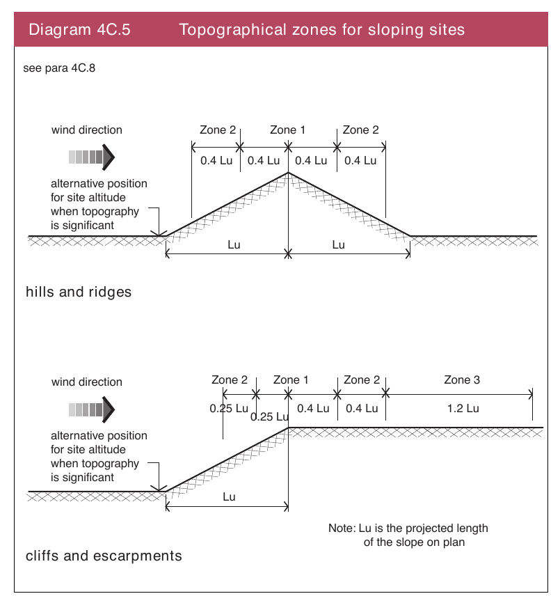
(b)the topography of the ground surrounding the building; and
(c)the type of terrain in which the building is located (e.g. in a town or out in the country).
4C.8 The procedure to determine the maximum height of a building that falls
Page 64
#Source page 64
Diagram 4C.4 Wind speed “V” (m/s)
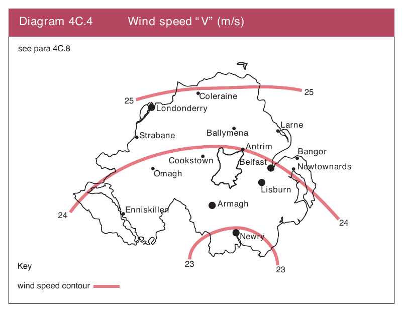
Diagram 4C.5 Topographical zones for sloping sites
Page 65
#Source page 65
Table 4C.2 Factor “T” (determined in conjunction with Diagram 4C.5)
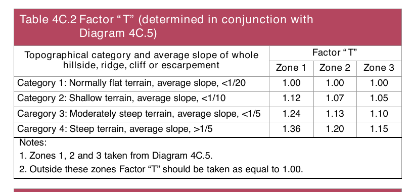
Table 4C.3 Factor “A” (dependent upon the site altitude)
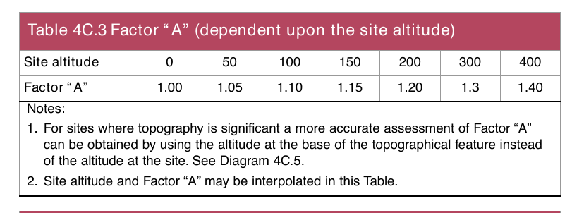
| Table 4C.4 Maximum allowable height of building (m) | ||||||
|---|---|---|---|---|---|---|
| Factor “S” (S=VxTxA) | Country sites | Town sites | ||||
| Distance to the coast (Km) | Distance to the coast (Km) | |||||
| less than 10 | 10 to 50 | more than 50 | less than 10 | 10 to 50 | more than 50 | |
| 24 | 15 | 15 | 15 | 15 | 15 | 15 |
| 25 | 11.5 | 14.5 | 15 | 15 | 15 | 15 |
| 26 | 8 | 10.5 | 13 | 15 | 15 | 15 |
| 27 | 6 | 8.5 | 10 | 15 | 15 | 15 |
| 28 | 4.5 | 6.5 | 8 | 13.5 | 15 | 15 |
| 29 | 3.5 | 5 | 6 | 11 | 13 | 14.5 |
| 30 | 3 | 4 | 5 | 9 | 11 | 12.5 |
| 31 | 3.5 | 4 | 8 | 9.5 | 10.5 | |
| 32 | 3 | 3.5 | 7 | 8.5 | 9.5 | |
| 33 | 3 | 6 | 7.5 | 8.5 | ||
| 34 | 5 | 7 | 8 | |||
| 35 | 4 | 6 | 7 | |||
| 36 | 3 | 5.5 | 6 | |||
| 37 | 4.5 | 5.5 | ||||
| 38 | 4 | 5 | ||||
| 39 | 3 | 4 | ||||
| 40 | 3 | |||||
| Notes: 1. Sites in town less than 300 m from the edge of town should be assumed to be in country terrain. 2. For sites closer than 1 km to an inland body of water which extends more than 1 km in the direction of the wind, the distance to the coast should be taken from the edge of that body of water. 3. The maximum allowable building heights may be interpolation within in this Table. |
Conditions relating to the wall
#Source page 66
| Length and height of wall | |
|---|---|
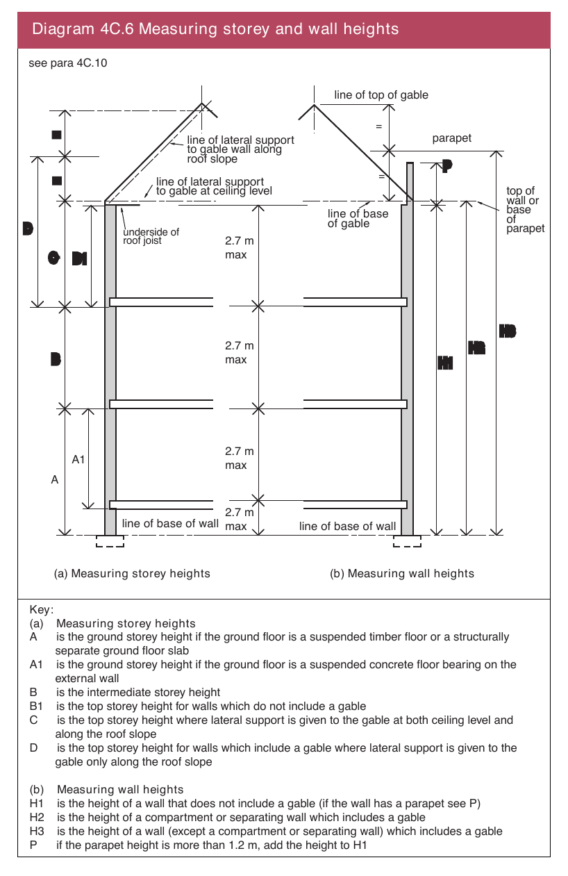
| 4C.9 | The wall should not exceed 12 m in length, measured from centre to centre of buttressing walls, piers or chimneys providing restraint, and not exceed 12 m in height. |
| 4C.10 | The height of a wall or a storey should be measured in accordance with the rules in Diagram 4C.6. |
Diagram 4C.6 Measuring storey and wall heights
Construction materials and workmanship
#Source page 67
Cavity wall ties
4C.11 The cavity wall ties should comply with BS EN 845 1 and DD 140 2 and should be material references 1 or 3 in BS EN 845 1: Table A.1, austenitic stainless steel. Wall ties should be selected in accordance with Table 4C.5.
Table 4C.5 Cavity wall ties
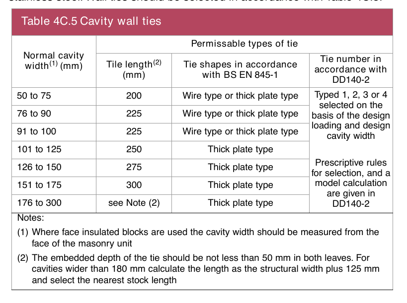
4C.12 The cavity wall ties should have a horizontal spacing of 900 mm and a vertical spacing of 450 mm, which is equivalent to 2.5 ties per square metre. Wall ties should also be spaced not greater than 300 mm apart vertically, within a distance of 225 mm from the vertical edge of any opening, movement joint and roof verge.
Brick and block construction
4C.13 The wall should be properly bonded and solidly put together with mortar and constructed of –
(a)clay bricks conforming to BS EN 7711;
(b)calcium silicate bricks conforming to BS EN 7712;
(c)concrete bricks or blocks conforming to BS EN 7713;
(d)autoclaved aerated concrete masonry units to BS EN 7714;
(e)manufactured stone complying with BS EN 7715;or
(f)square dressed natural stone conforming to the appropriate requirements described in BS EN 7716.
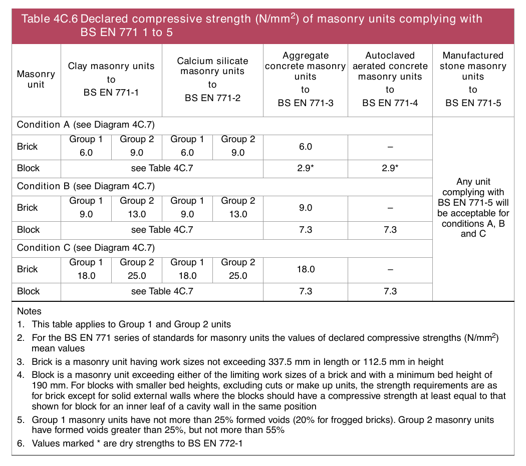
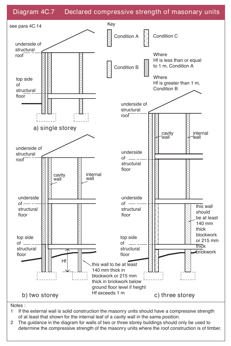
4C.14 The masonry units indicated for Conditions A, B and C in Diagram 4C.7 should have the declared compressive strengths as given in Table 4C.6 as designated in BS EN 771. The normalised compressive strengths for block sized clay and calcium silicate masonry units not complying with the brick dimensional format are given in Table 4C.7.
Page 68
#Source page 68
Table 4C.6 Declared compressive strength (N/mm2) of masonry units complying with BS EN 771 1 to 5
| Table 4C.7 Normalised compressive strength (N/mm²) of masonry units of clay and calcium silicate blocks complying with BS EN 771 1 and 2 | |||
|---|---|---|---|
| Standard | Condition | Group 1 masonary units | Group 2 masonary units |
| Clay masonry units to BS EN 7711 and Calcium silicate masonry units to BS EN 7712 | A | 5.0 | 8.0 |
| B | 7.5 | 11.0 | |
| C | 15.0 | 21.0 | |
| Notes: 1. Values in this Table are normalised compressive strengths (N/mm²). Compressive strengths of masonry units should be derived according to BS EN 7721. 2. The Table applies to clay and calcium silicate block masonry units where the work size exceeds 337.5 mm in length or 112.5 mm in height. 3. Group 1 masonry units have not more than 25% formed voids (20% for frogged bricks). Group 2 masonry units have formed voids greater than 25%, but not more than 55%. |
4C.15 Mortar should be –
#Source page 69
(a)of mortar designation (iii) as given in BS 5628: Part 1;
(b)strength class M4 as given in BS EN 998 2; or
(c)CEM1, lime and fine aggregate mixed in the ratio of 1:1:5 measured by volume of dry materials.
Diagram 4C.7 Declared compressive strength of masonary units
Loading on walls
#Source page 70
Maximum span of floors
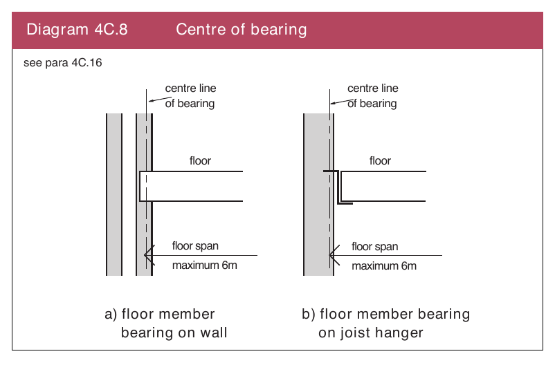
4C.16 The maximum span for any floor supported by a wall should not exceed 6 m where the span is measured centretocentre of bearing (see Diagram 4C.8).
Diagram 4C.8 Centre of bearing
Other loading conditions
4C.17 Vertical and lateral loading should be limited to and assessed as follows –
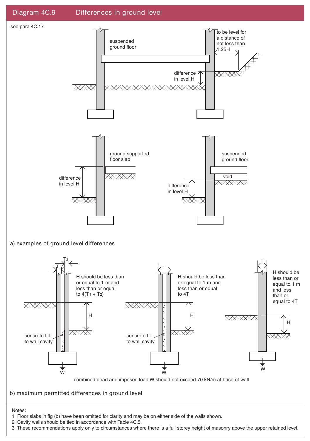
(a)the combined dead and imposed load should not exceed 70 kN/m at base of wall (see Diagram 4C.9);
(b)vertical loading on walls should be distributed. This may be assumed for concrete floor slabs, precast concrete floors, and timber floors designed in accordance with part B of this Section, and where the bearing length for lintels is 150 mm or greater. Where a lintel has a clear span of 1200 mm or less, the bearing length may be reduced to 100 mm. Where lintels carry a concrete floor the bearing length should be not less than 150 mm or L/10, whichever is the greater and where
•L is the clear span of the lintel;
(c)walls must be not subject to lateral load other than from wind, and that covered by paragraph 4C.17(d); and
(d)differences in level of ground or other solid construction between one side of the wall and the other should not exceed 4 times the thickness of the wall as shown in Diagram 4C.9.
Page 71
#Source page 71
Diagram 4C.9 Differences in ground level
Wall restraints Vertical restraint by buttressing walls, piers and chimneys
#Source page 72
General
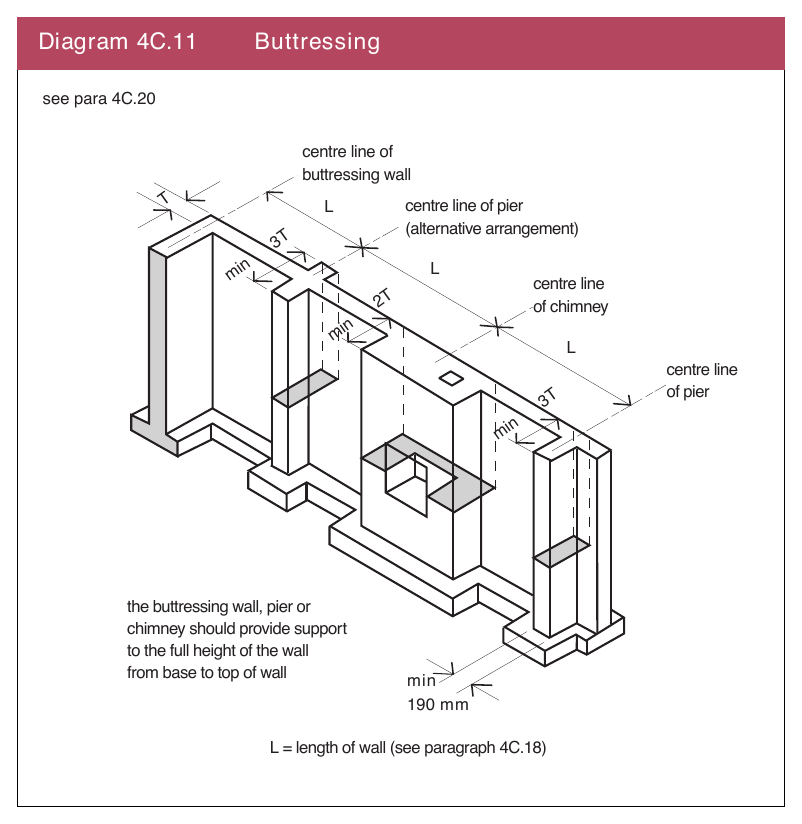
4C.18 The ends of every wall should be bonded or otherwise securely tied throughout their full height to a buttressing wall, pier or chimney. Long walls may be provided with intermediate buttressing walls, piers or chimneys dividing the wall into distinct lengths (L) within each storey; each distinct length is a supported wall for the purposes of this Section. The intermediate buttressing walls, piers or chimneys should provide lateral restraint to the full height of the supported wall, but they may be staggered at each storey.
Design criteria for buttressing walls
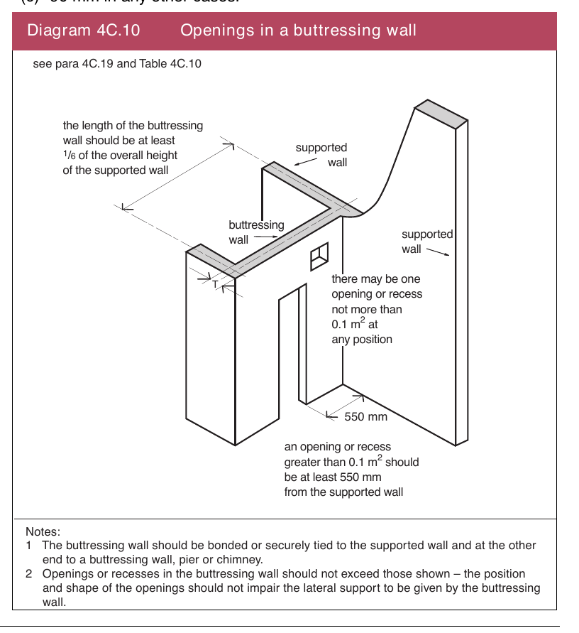
4C.19 Diagram 4C.10 gives certain rules for masonry buttressing walls. Additionally if the buttressing wall is not itself a supported wall, its thickness T should be not less than –
(a)half the thickness required by this Section for an external or separating wall of similar height and length, less 5 mm;
(b)75 mm if the wall forms part of a house and does not exceed 6 m in total height and 10 m in length; or
(c)90 mm in any other cases.
Diagram 4C.10 Openings in a buttressing wall
Page 73
#Source page 73
Design criteria for piers and chimneys providing restraint
4C.20 Piers should measure at least 3 times the thickness of the supported wall and chimneys twice the thickness, measured at right angles to the wall. Piers should have a minimum width of 190 mm (see Diagram 4C.11).
The sectional area on plan of chimneys (excluding openings for fireplaces and flues) should be not less than the area required for a pier in the same wall, and the overall thickness not less than twice the required thickness of the supported wall (see Diagram 4C.11).
Diagram 4C.11 Buttressing
Wall restraints Lateral restraint by floors and roofs
#Source page 74
| 4C.21 | Walls in each storey of a building should extend to the full height of that storey, and have horizontal lateral supports to restrict movement of the wall at right angles to its plane. |
| 4C.22 | Floors and roofs should – |
| (a) act to transfer lateral forces from walls to buttressing walls, piers or chimneys; and | |
| (b) be secured to the supported wall by connections specified in paragraphs 4C.23 to 4C.25 and Table 4C.8. |
| Table 4C.8 Lateral support for walls | ||
|---|---|---|
| Wall type | Supported wall length | Lateral support required |
| External, compartment or separating wall (solid or cavity) | Any length | Roof lateral support by every roof forming a junction with the supported wall |
| Greater than 3 m | Floor lateral support by every floor forming a junction with the supported wall | |
| Internal loadbearing wall (not being a compartment or separating wall) | Any length | Roof or floor lateral support at the top of each storey |
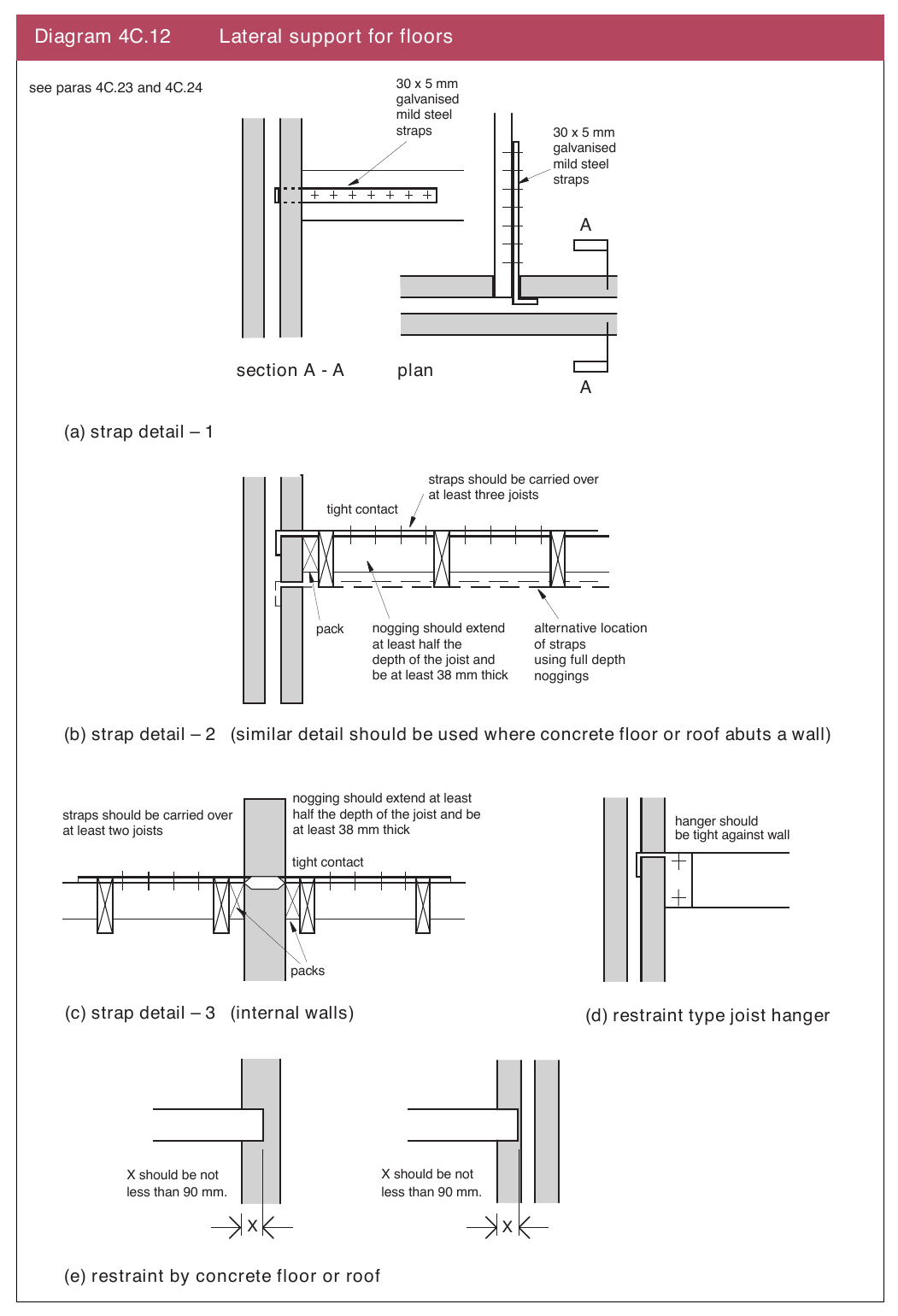
4C.23 The wall should be strapped to the floors above ground level, at intervals not exceeding 2 m and as shown in Diagrams 4C.12(a), (b) and (c) by tension straps conforming to BS EN 845–1. For corrosion resistance purposes, the tension straps should be material reference 14 or 16.1 or 16.2 (galvanised mild steel) or other more resistant specifications including material references 1 or 3 (austenitic stainless steel). The minimum crosssection of the strap should be 30 mm x 5 mm.
4C.24 Tension straps need be not provided –
(a)in the longitudinal direction of floor joists in houses of not more than 2 storeys, if the joists are at not more than 1.2 m centres and have at least 90 mm bearing on the supported walls or 75 mm bearing on a timber wallplate at each end;
(b)in the longitudinal direction of floor joists in houses of not more than 2 storeys, if the joists are carried on the supported wall by joist hangers in accordance with BS EN 8451 of the restraint type described in BS 5628: Part 1 and shown in Diagram 4C.12(d), and are incorporated at not more than 2 m centres;
(c)when a concrete floor has at least 90 mm bearing on the supported wall (see Diagram 4C.12(e)); and
(d)where the floor is at, or about, the same level on each side of the wall, and contact between the floors and the wall is either continuous or at intervals not greater than 2 m. Where contact is intermittent, the points of contact should be in line, or nearly in line, on plan.
Page 75
#Source page 75
Diagram 4C.12 Lateral support for floors
Page 76
#Source page 76
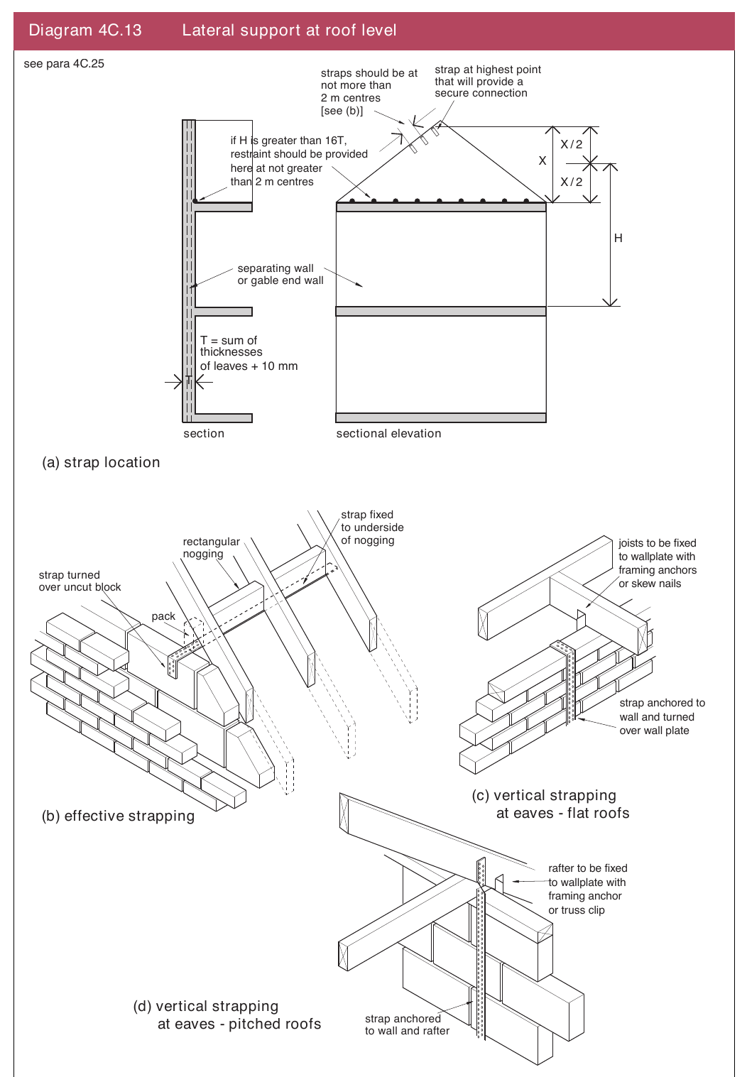
4C.25 The gable wall should be strapped to the roof as shown in Diagram 4C.13(a) and (b) by tension straps as described in paragraph 4C.23. Vertical strapping at least 1 m long having a minimum crosssection of 30 mm x 5 mm should be provided at eaves level at intervals not exceeding 2 m (see Diagram 4C.13(c) and 4C.13(d)).
Vertical strapping is not required if the roof –
(a)has a pitch greater than 15°;
(b)is clad in tiles or slates with a laid mass per unit area greater than 50 kg/m2;
(c)is part of a building in a low wind exposure area; and
(d)has main timber members spanning onto the supported wall at not more than 1.2 m centres.
Interruption of lateral support
4C.26 Where an opening in a floor or roof for a stairway or the like adjoins a supported wall and interrupts the continuity of lateral support, the following provisions should be made –
(a)the maximum permitted length of the opening should be 3 m, measured parallel to the supported wall;
(b)where a connection is provided by means other than by anchor, this must be provided throughout the length of each portion of the wall situated on each side of the opening;
(c)where connection is provided by tension straps, these must be spaced closer than 2 m on each side of the opening to provide the same number of straps as if there were no opening; and
(d)no other interruption of lateral support is permissible.
Page 77
#Source page 77
Diagram 4C.13 Lateral support at roof level
Openings, recesses, overhangs and chases
#Source page 78
| 4C.27 | The number, size and position of openings and recesses should not impair the stability of a wall or the lateral support afforded by a buttressing wall to a supported wall. Construction over openings and recesses should be adequately supported. |
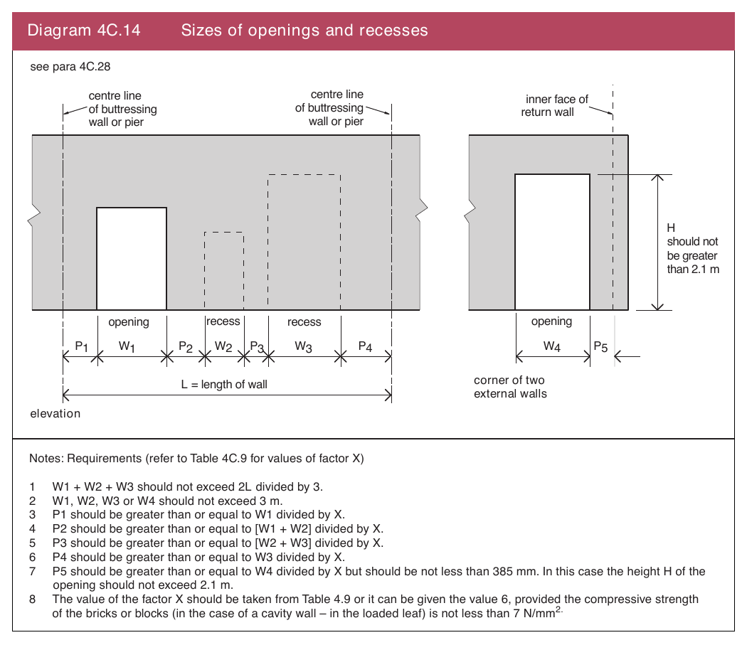
| 4C.28 | The dimensional criteria for openings and recesses are given in Table 4C.9 and Diagram 4C.14 . |
| Table 4C | .9 Value o | f “X” (see | Diagram 4C.14) | ||||
|---|---|---|---|---|---|---|---|
| Nature of roof span | Maximum roof span (m) | Minimum thickness of wall inner leaf (mm) | Span of floor is parallel to wall | Span of timber floor into wall (m) | Span of concrete floor into wall (m) | ||
| 4.5 | 6.0 | 4.5 | 6.0 | ||||
| Value of X | |||||||
| Roof spans parallel to wall | Not applicable | 100 | 6 | 6 | 6 | 6 | 6 |
| 90 | 6 | 6 | 6 | 6 | 5 | ||
| Timber roof spans into wall | 9 | 100 | 6 | 6 | 5 | 4 | 3 |
| 90 | 6 | 4 | 4 | 3 | 3 |
4C.29 All chases should comply with the following –
(a)vertical chases should be not deeper than one third of the wall thickness or, in cavity walls, one third of the thickness of the leaf;
(b)horizontal chases should be not deeper than one sixth of the thickness of the leaf or wall; and
(c)chases should be positioned so as not to impair the stability of the wall, particularly where hollow blocks are used.
4C.30 The projection of any overhang should not impair the stability of the wall.
Page 79
#Source page 79
Diagram 4C.14 Sizes of openings and recesses
Wall thickness
#Source page 80
General
4C.31 The wall thickness may be determined according to this Part provided that –
(a)“Conditions relating to the building of which the wall forms a part” (see paragraphs 4C.4 to 4C.8) are met; and
(b)“Conditions relating to the wall” (see paragraphs 4C.9 to 4C.30) are met.
If any one of the conditions in these paragraphs is not met, the sizing of the wall is outside the scope of this Section and specialist advice should be obtained from a suitably qualified person.
Solid external, compartment and separating walls
4C.32 Solid external, compartment and separating walls in coursed brickwork or blockwork should be at least as thick as 1/16 of the storey height. Further requirements are given in Table 4C.10.
| Table 4C.10 Minimum thickness of certain external walls, compartment walls and separating walls | ||
|---|---|---|
| Overall height of supported wall(1) | Length of supported wall(2) | Minimum thickness of supported wall |
| not exceeding 3.5 m | not exceeding 12 m | 190 mm for the whole of its height |
| exceeding 3.5 m but not exceeding 9 m | not exceeding 9 m | 190 mm for the whole of its height |
| exceeding 9 m but not exceeding 12 m | 290 mm from the base for the height of one storey, and 190 mm for the rest of its height | |
| exceeding 9 m but not exceeding 12 m | not exceeding 9 m | 290 mm from the base for the height of one storey, and 190 mm for the rest of its height |
| exceeding 9 m but not exceeding 12 m | 290 mm from the base for the height of two storeys, and 190 mm for the rest of its height | |
| Notes: (1) See Diagram 4C.6 (2) See Diagram 4C.11 |
Uncoursed stone or flint
4C.33 The thickness of walls constructed in uncoursed stone, flints or other burnt or vitrified material should be not less than 1.33 times the thickness required by paragraph 4C.32.
Cavity walls
4C.34 All cavity walls should have leaves not less than 90 mm thick and cavities not less than 50 mm wide.
For external, compartment and separating walls in cavity construction, the combined thickness of the 2 leaves plus 10 mm should be not less than the thickness required by paragraph 4C.32 for a solid wall of the same height and length.
Page 81
#Source page 81
Walls providing vertical support to other walls
4C.35 Irrespective of the materials used in the construction, a wall that provides vertical support to another wall should be not less in thickness than any part of the wall to which it gives vertical support.
Internal load bearing masonry walls
4C.36 Internal loadbearing masonry walls should have a thickness not less than –
(specified thickness from Table 4C.10)
– 5 mm
2 except for a wall in the lowest storey of a 3 storey building, carrying load from both upper storeys, which should have a thickness as determined by the above equation or 140 mm, whichever is the greater.
Parapet walls
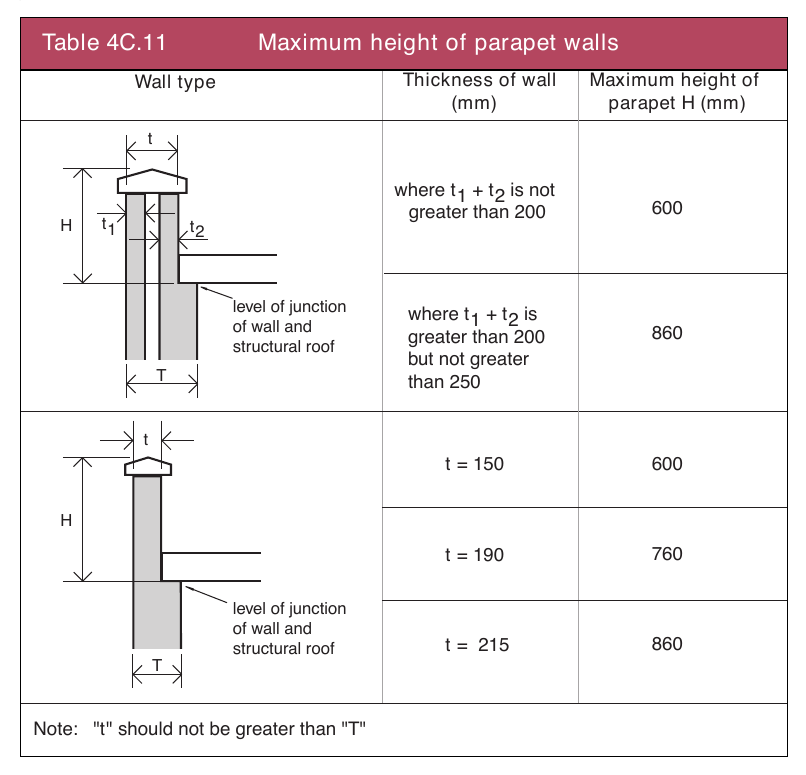
4C.37 The minimum thickness and maximum height of parapet walls should be as given in Table 4C.11.
Table 4C.11 Maximum height of parapet walls
4C.38 Where a wall is constructed of bricks or blocks having modular dimensions derived from BS 6750, the wall thicknesses prescribed in this Part which derive from a dimension of a brick or block may be reduced by an amount not exceeding the deviation from work size permitted by a British Standard relating to equivalent sized bricks or blocks made of the same material.
4C Masonry walls. Part 2 Masonry walls for annexes and small single storey buildings
#Source page 82
Application of this Part of the Section
4C.39 This Part of the Section applies to –
(a)an annex to a house; and
(b)a small single storey building other than a dwelling.
4C.40 The provisions contained in this Part apply only if the following criteria are met –
(a)the floor area of the annex or building is not greater than 36 m2;
(b)the walls are solidly constructed in brickwork or blockwork using materials that comply with Tables 4C.6 and 4C.7;
(c)where the floor area of the annex or building is greater than 10 m2, the walls have a surface mass of not less than 130 kg/m2;
•Note: There is no surface mass limitation recommended for floor areas of 10 m2 or less.;
(d)access to the roof is solely for the purposes of maintenance and repair;
(e)the only lateral loads are wind loads;
(f)the maximum length or width of the annex or building is not greater than 9 m;
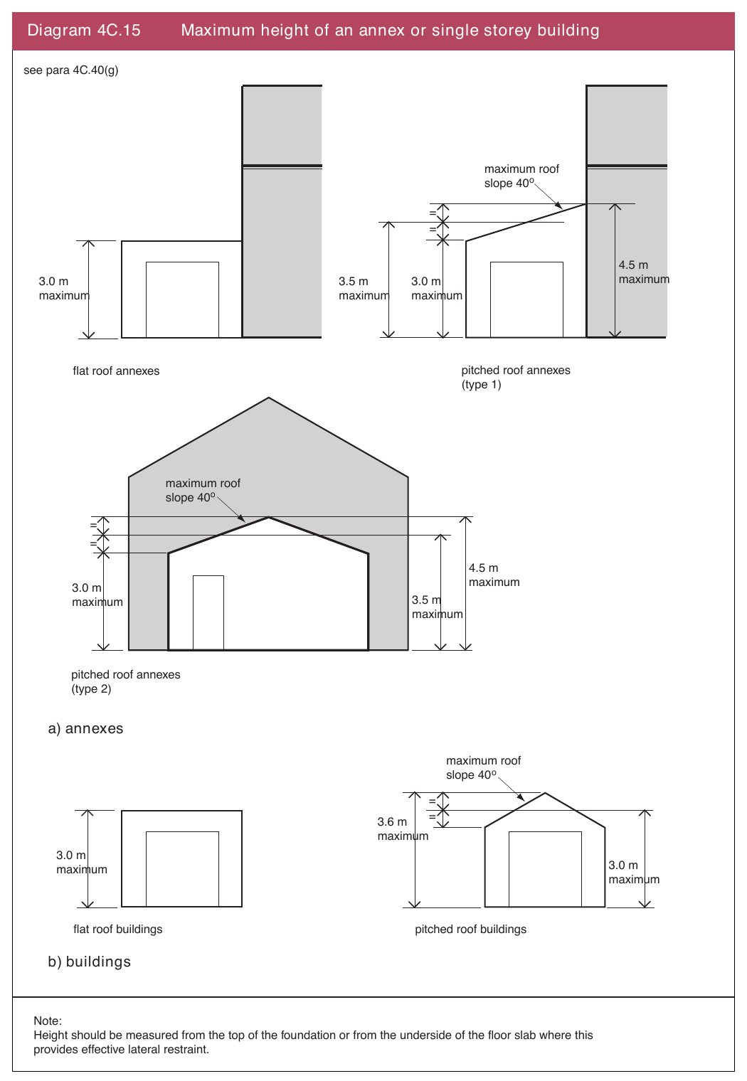
(g)the height of the annex or building is not greater than the lower value derived from Diagram 4C.15 or paragraphs 4C.7 and 4C.8;
(h)the roof is braced at rafter level, horizontally at eaves level and at the base of any gable by roof decking, rigid sarking or diagonal timber bracing, as appropriate, in accordance with BS 8103: Part 3;
(i)the walls are tied to the roof structure vertically and horizontally in accordance with BS 8103: Part 1 and with horizontal lateral restraint at roof level in accordance with paragraph 4C.43; and
(j)the roof structure of an annex is secured to the structure of the main building at both rafter and eaves level.
Page 83
#Source page 83
Diagram 4C.15 Maximum height of an annex or single storey building
Page 84
#Source page 84
Size and location of openings
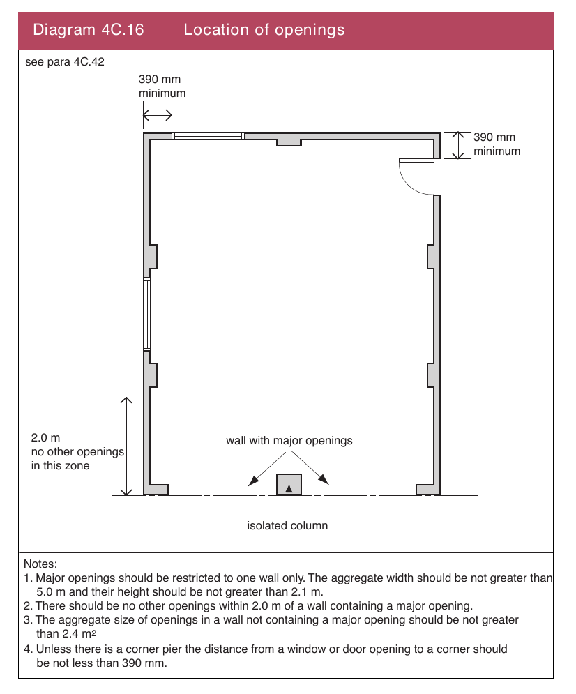
4C.41 One or two major openings not more than 2.1 m in height are permitted in one wall of the building or annex only. The width of a single opening or the combined width of two openings should not exceed 5 m.
4C.42 The only other openings permitted in an annex or building are for windows and a single leaf door. The size and location of these openings should be in accordance with Diagram 4C.16.
Diagram 4C.16 Location of openings
Horizontal lateral restraint at roof level
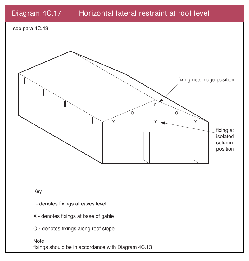
4C.43 Walls should be tied horizontally at not more than 2 m centres to the roof structure at eaves level, base of gables and along roof slopes with straps fixed in accordance with Diagrams 4C.13 and 4C.17. Where straps cannot pass through a wall they should be adequately secured to the masonry using suitable fixings. Isolated columns should also be tied to the roof structure.
Page 85
#Source page 85
Diagram 4C.17 Horizontal lateral restraint at roof level
Wall thickness and recommendations for piers
4C.44 The walls should have a minimum thickness of 90 mm.
4C.45 Walls which do not contain a major opening but exceed 2.5 m in length or height should be bonded or tied to piers for their full height at not greater than 3 m centres as shown in Diagram 4C.18.
4C.46 A wall, which contains one or two major openings, should in addition have piers as shown in Diagram 4C.18. Where ties are used to connect piers to walls they should be flat, 20 mm x 3 mm in cross section, be stainless steel, placed in pairs and spaced at not greater than 300 mm centres vertically.
c) wall with two major openings
#Source page 86
Diagram 4C.18 Wall thicknesses

see paras 4C.45 and 4C.46 Ap Ap 90 mm
●● ● ●
●● ● ● minimum
●●● ●● ●
●●● ●● ●
a)wall without a major opening
| ● | ● Bp ● W ● | ||
|---|---|---|---|
| Ap ● ● | ● ● | ||
| ● ● | ● ● |
| ●● Bp ● G ● | |||||
|---|---|---|---|---|---|
| Ap ● ● | ● | ||||
| ● ● | ● |
Ap
G
orientation of piers with opening orientation of piers with opening width G not greater than 2.5 m width G greater than 2.5 m
b)walls with a single major opening
| Ap ● ● | ||
|---|---|---|
| ● ● |
| ● ● | |
|---|---|
| Cc ● ● | |
| ● ● |
Cc
c) wall with two major openings
Notes:
1. In all cases the minimum pier size (Ap x Bp) should be (390 mm x 190 mm) or (327 mm x 215 mm) depending on the size of the masonry units
.
2.Isolated columns (Case c) to be 325 mm x 325 mm minimum (Cc x Cc).
4D Masonry chimneys
#Source page 87
Proportions for masonry chimneys above the roof surface
Application
This Section applies to a single family house of not more than 3 storeys in height, an annex and a small single storey building other than a dwelling.
Height to width relationship
4D.1 Where a chimney is not adequately supported by ties or securely restrained in any way, its height, measured from the highest point of intersection with the roof surface, gutter, etc, should not exceed 4.5 W, where –
W is the least horizontal dimension of the chimney measured at the same point of intersection; and
H is measured to the top of any chimney pot or other flue terminal.
Where the density of the masonry is less than 1500 kg/m3 the 4.5 height factor should be reduced prorata.
(See Diagram 4D.1).
Diagram 4D.1 Proportions for masonry chimneys
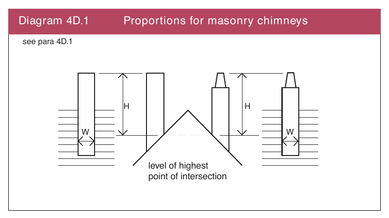
4E Concrete foundations
#Source page 88
Strip foundations of plain concrete
Application
This Section applies to a single family house of not more than 3 storeys in height, an annex and a small single storey building other than a dwelling.
Conditions relating to the subsoil
4E.1 There should not be –
(a)any made ground, peat or wide variation in the type of subsoil within the loaded area;
(b)a weaker type of soil at such a depth below the soil on which the foundation rests as could impair the stability of the structure; or
(c)soil movement within the loaded area resulting from seasonal weather changes.
Foundation concrete
4E.2 The mass concrete used in the strip foundation should be –
(a)in chemically aggressive soil conditions, an appropriate concrete mix as recommended in BS 8500: Part 1 and BRE Special Digest 1; and
(b)in chemically nonaggressive soils, composed of Portland Cement to BS EN 1971 & 2 and fine and course aggregate conforming to BS EN 12620, the mix being –
(i)in the proportion of 50 kg of cement to not more than 155 kg (0.11 m3) of fine aggregate and 240 kg (0.16 m3) of coarse aggregate; or
(ii)Grade ST2 or Grade GEN 1 to BS 8500: Part 2.
Design provisions
4E.3 The following design provisions apply –
(a)the foundation should be situated centrally under the wall;
(b)the foundation should have the minimum width given in Table 4E.1;
(c)the minimum thickness T of concrete foundations should be 150 mm or P, whichever is the greater, where P is derived using Table 4E.1, see Diagram 4E.1(a) and (b);
(d)where the foundation is stepped on elevation, it should overlap by twice the height of the step, the thickness of the foundation, or 300 mm, whichever is greater (see Diagram 4E.2). For trench filled foundations the overlap should be twice the height of the step or 1000 mm, whichever is greater;
(e)the step in a foundation should not be of greater height than the thickness of the foundation (see Diagram 4E.2); and
(f)the foundation of a pier, buttress or chimney should project as indicated in Diagram 4E.3, the projection X should be not less than P.
Page 89
#Source page 89
Diagram 4E.1 Foundation dimensions
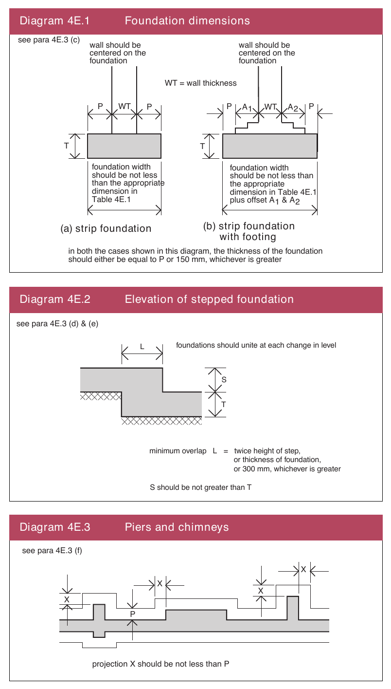
Page 90
#Source page 90
Minimum width of strip foundations
4E.4 Provided that the conditions relating to the subsoil (paragraph 4E.1) and design provisions relating to the foundations (paragraph 4E.3) are observed, the type and condition of subsoil are known and the loading at the base of the wall is within acceptable limits, the widths of foundations given in Table 4E.1 may be used.
| Tabl | e 4E.1 Mi | nimum wi | dth of strip fou | ndations | |||||
|---|---|---|---|---|---|---|---|---|---|
| Type No. | Type of subsoil | Condition of subsoil | Field test applicable | Total load of load bearing wall not greater than (kN/m) | |||||
| 20 | 30 | 40 | 50 | 60 | 70 | ||||
| Minimum width of strip foundation (mm) | |||||||||
| 1 | Rock | Not inferior to sandstone, limestone or firm chalk | Requires at least a pneumatic or other mechanically operated pick for excavation | In each case not less than the width of the wall | |||||
| 2 | Gravel or sand | Medium dense | Requires pick for excavation. Wooden peg 50 mm square in cross section hard to drive beyond 150 mm | 250 | 300 | 400 | 500 | 600 | 650 |
| 3 | Clay or sandy clay | Stiff | Can be indented slightly by thumb | 250 | 300 | 400 | 500 | 600 | 650 |
| 4 | Clay or sandy clay | Firm | Thumb makes impression easily | 300 | 350 | 450 | 600 | 750 | 850 |
| 5 | Sand, silty sand or clayey sand | Loose | Can be excavated with a spade. Wooden peg 50 mm square in cross section can be easily driven | 400 | 600 | Note: Foundations on subsoil types 5 & 6 do not fall within the provisions of this Section if the total load exceeds 30 kN/m. | |||
| 6 | Silt, clay or sandy clay & silt | Soft | Finger pushes in up to 10 mm | 450 | 650 | ||||
| 7 | Silt, clay or sandy clay & silt | Very soft | Finger easily pushes in up to 25 mm | Refer to specialist advice |
Page 91
#Source page 91
Minimum depth of strip foundations
4E.5 The minimum depth to the underside of a strip foundation should be the greater of –
(a)the depth to selected bearing stratum; or
(b)a depth of 450 mm to the underside of foundations. This should avoid damage from frost action in normal soil conditions although this depth may have to be increased in areas which are subject to long periods of frost or in order to transfer the loading onto satisfactory ground.
The susceptibility of ground to movement, action of frost and changes in water table varies widely and the advice of a suitably qualified person should be sought if the conditions are outside the parameters set out above. More detailed guidance is provided in BRE Digests 240 and 241.
BS EN 336: 2003 Structural timber. Sizes, permitted deviations.
#Source page 92
Appendix Publications referred to
| BS EN 197: Cement. | |
|---|---|
| Part 1: 2000 | Composition, specifications and conformity |
| criteria for common element. | |
| AMD 15209, AMD 17352 | |
| Part 2: 2000 | Conformity evaluation. |
BS EN 336: 2003 Structural timber. Sizes, permitted deviations.
AMD 14533, AMD 16208
BS EN 771: Specification for Masonry Units.
Part 1: 2003 Clay masonry units. AMD 15998
Part 2: 2003 Calcium silicate masonry units. AMD 15974
Part 3: 2003 Aggregate concrete masonry units. AMD 16001
Part 4: 2003 Autoclaved aerated concrete masonry units. AMD 16000
Part 5: 2003 Manufactured stone masonry units. AMD 15999
Part 6: 2005 Natural stone masonry units.
BS EN 845: Specification for ancillary components for masonry.
Part 1: 2003 Ties, tension straps, hangers and brackets. AMD 14736, AMD 15539
BS EN 998: Specification for mortar for masonry.
Part 2: 2003 Masonry mortar.
BS EN 1313: Round and sawn timber Permitted deviations and preferred sizes.
Part 1: 2010 Softwood sawn timber. AMD 11020
BS EN 1991: Action on structures
Part 11: 2002 General actions Densities, selfweight and imposed loads. Part 13: 2003 General actions Snow loads. Part 14: 2005 General actions Wind actions. Part 17: 2006 General actions Accidential actions
BS EN 1992: Design of concrete structures.
#Source page 93
Part 11: 2004 General rules and rules for building. Part 12: 2004 General rules. Structural fire design.
BS EN 1993: Design of steel structures.
Part 11: 2005 General rules and rules for building. Part 12: 2005 Structural fire design. Part 13: 2006 Supplementary rules for cold formed members and sheeting. Part 15: 2006 Plated structural elements. Part 18: 2005 Design of joints.
AMD16291, AMD16571 Part 110: 2005 Material toughness and throughthickness properties. AMD16293, AMD16569
BS EN 1994: Design of composite concrete and steel structures
Part 11: 2004 General rules and rules for building. Part 12: 2005 Structural fire design.
BS EN 1995: Design of timber structures.
Part 11: 2004 General – Common rules and rules for building. Part 12: 2004 Structural fire design.
BS EN 1996: Design of masonry structures.
Part 11: 2005 General rules for reinforced and unreinforced masonry structures. Part 12: 2005 Structural fire design. Part 3: 2006 Simplified calculations methods.
BS EN 1997:Geotechnical Design
Part 1: 2004 General rules.
BS EN 1999: Design of aluminium structures
Part 11: 2007 General structural rules. Part 12: 2007 Structural fire design. Part 13: 2007 Structures susceptible to fatigue.
BS EN 12620: 2002 Aggregates for concrete.
AMD 15333
BS 5268: Structural use of timber.
#Source page 94
BS EN 14081: Timber structures – Strength graded structural timber with rectangular cross section.
Part 1: 2005 General requirements.
BS 1297: 1987 Specification for tongue and grooved softwood flooring. BS 4978: 2007 Specification for visual strength grading of softwood.
AMD 9434
BS 5268: Structural use of timber.
Part 2: 2002 Code of practice for permissible stress design, materials and workmanship.
Part 3: 2006 Code of practice for trussed rafter roofs. AMD 16541, AMD 16972
BS 5628: Code of practice for use of masonry.
Part 1: 2005 Structural use of unreinforced masonry. Part 2: 2005 Structural use of reinforced and restressed masonry Part 3: 2005 Materials and components, design and workmanship.
BS 5950: Structural use of steelwork in a building.
Part 1: 2000 Code of practice for design. Rolled and welded sections. AMD 13199
Part 2: 2001 Specification for materials, fabrication and erection, hot rolled sections.
Part 3.1: 1990 Design in composite construction. Code of practice for design of simple and continuous composite beams.
Part 4: 1994 Code of practice for design of composite slabs with profiled steel sheeting.
Part 5: 1998 Code of practice for design of cold formed thin gauge sections.
BS 6399: Loading for buildings.
Part 1: 1996 Code of practice for dead and imposed loads.
Part 2: 1997 Code of practice for wind loads. AMD 13392, AMD 14009
Part 3: 1988 Code of practice for imposed roof loads. AMD 6033, AMD 9187, AMD 9452
BS 6750: 1986 Specification for modular coordination in building. BS 8004:1986 Code of practice for foundations
DD1402: 1987 Wall ties. Recommendations for design of wall ties.
#Source page 95
BS 8103: Structural design of lowrise buildings.
| Part 1: 1995 | Code of practice for stability, site investigation, foundations and ground floor slabs for housing. AMD 8980 |
| Part 2: 2005 | Code of practice for masonry walls for housing. |
| Part 3: 2009 | Code of practice for timber floors and roofs for housing. |
| Part 4: 1995 | Code of practice for suspended concrete floors for housing. |
BS 8110: Structural use of concrete.
Part 1: 1997 Code of practice for design and construction. AMD 9882, AMD 13468, AMD16016, AMD 17307
Part 2: 1985 Code of practice for special circumstances. AMD 5914, AMD 12061, AMD 16017
Part 3: 1985 Design charts for singly reinforced beams, doubly reinforced beams and rectangular columns.
BS 8118: Structural use of aluminium.
Part 1: 1991 Code of practice for design. Part 2: 1991 Specification for materials, workmanship and protection.
BS 8500: Concrete. Complementary British Standard to BS EN 2061.
Part 1: 2006 Method of specifying and guidance for the specifier.
Part 2: 2006 Specification for constituent materials and concrete.
DD1402: 1987 Wall ties. Recommendations for design of wall ties.
AMD 7971 BRE Special Digest 1 – Concrete in aggressive ground, 3rd Edition. BRE Digest 240 – Lowrise buildings on shrinkable clay soils Part 1. BRE Digest 241 – Lowrise buildings on shrinkable clay soils Part 2. DFP Technical Booklet B: 2012 Materials and workmanship.
Page 96
#Source page 96
Technical Booklets
The following list comprises the series of Technical Booklets prepared by the Department for the purpose of providing practical guidance with respect to the technical requirements of the Building Regulations (Northern Ireland) 2012.
| Technical Booklet B | Materials and workmanship |
| Technical Booklet C | Preparation of site and resistance to |
| contaminants and moisture | |
| Technical Booklet D | Structure |
| Technical Booklet E | Fire safety |
| Technical Booklet F1 | Conservation of fuel and power in |
| dwellings | |
| Technical Booklet F2 | Conservation of fuel and power in buildings other |
| than dwellings | |
| Technical Booklet G | Resistance to the passage of sound |
| Technical Booklet H | Stairs, ramps, guarding and protection from |
| impact | |
| Technical Booklet J | Solid waste in buildings |
| Technical Booklet K | Ventilation |
| Technical Booklet L | Combustion appliances and fuel storage |
| systems | |
| Technical Booklet N | Drainage |
| Technical Booklet P | Sanitary appliances, unvented hot water storage |
| systems and reducing the risk of scalding | |
| Technical Booklet R | Access to and use of buildings |
| Technical Booklet V | Glazing |
Any person who intends to demonstrate compliance with the Building Regulations by following the guidance given in a Technical Booklet is advised to ensure that the guidance is current on the date when plans are deposited or notice given to the district council.