Northern Ireland Technical booklet E
Technical booklet E
Library captured 10 September 2026 · Source updated 22 August 2026
G u i d a n c e
#Source page 1

Fire safety T e c h n i c a l B o o k l e t E October 2012 Track changes version with 2022 and 2024 amendments
It is not an up to date consolidated version. The amendments from 2022 and 2024 are contained in Amendments Booklets AMD 7 and AMD 9 respectively.
#Source page 2
This version of Technical Booklet E (Fire safety) is the 2012 edition with amendments from 2022 and 2024 incorporated.
It is not an up to date consolidated version. The amendments from 2022 and 2024 are contained in Amendments Booklets AMD 7 and AMD 9 respectively.
Notes:
1.New text for 2024 amendments contained in AMD 9 document are marked in red.
2.New text for 2022 amendments contained in AMD 7 document are marked in blue.
3.Text that is deleted are struck-through.
Page 3
#Source page 3
Contents page
Introduction 4
Technical booklets 4
This Technical booklet 4
Protected buildings 5
Other legislation 5
Commission guidance papers and decisions 6
Part E Regulations 8
Guidance – Performance and introduction to provisions 11
Means of escape 11
Internal fire spread – Linings 14
Internal fire spread – Structure 14
External fire spread 16
Facilities and access for the Fire and Rescue Service 17
Fire safety information 18
Automatic fire suppression systems 19
Use of this Technical Booklet 20
Section 1 General 21
Definitions 21
General guidance 28
Performance of materials, products and structures 29
Reaction to Fire 30
Non-combustible materials 31
Materials of limited combustibility 31
Classification 32
Alternative approaches 33
Page 4
#Source page 4
Section 2 Means of escape 34
Dwellinghouses 34
Introduction 34
Common provisions 34
Roof space conversions 39
Automatic fire detection and fire alarm systems in dwellinghouses 41
Flats 44
Means of escape 44
Smoke control in common escape routes 44
Automatic fire detection and fire alarm systems in flats 44
Buildings other than dwellings 45
Horizontal part of the escape route 45
Vertical part of the escape route 58
General provisions 73
Section 3 Internal fire spread - Linings 81 (National classification) (European classification)
Classification of performance of materials or products 81
Classification of performance of materials or products 83
Performance of wall and ceiling linings 84
Section 4 Internal fire spread - Structure 87
Tests for fire resistance 88
Fire resistance of elements of structure and certain other components of the building 94
Compartmentation 102
Protected shafts between compartments 107
Fire doors 109
Provision of cavity barriers 113
Pipes penetrating fire separating elements 121
Car parks for light vehicles 125
Shopping complexes 127
Insulating core panels used for internal structures 128
Page 5
#Source page 5
Section 5 External fire spread 132
Combustibility of external walls 132
Regulation 23(2) 135
Space separation - External walls 137
Provisions for and calculation of space separation and unprotected areas 141
Canopies 150
Roofs 151
Section 6 Facilities and access for the Fire and Rescue Service 158
Firefighting shafts 158
Venting of heat and smoke from basements 164
Rolling shutters in compartment walls 166
Vehicle access 166
Evacuation alert systems 169
Wayfinding signage 169
Secure Information Boxes 170
Section 7 Fire safety information 171
Introduction 171
Details of information 171
Section 8 Automatic fire suppression systems 174
Sprinklers 174
Regulation 37B 174
Design of sprinkler systems 175
Water supplies and pumps 175
Other automatic fire suppression systems 176
Appendix A Purpose Groups 177
Appendix B Rules for measurement 179
Appendix C Publications referred to 183
Page 6
#Source page 6
Introduction
Technical Booklets
This Technical Booklet, which takes effect on 31st October 2012, is one of a series that has been prepared by the Department of Finance and Personnel (the Department) for the purpose of providing practical guidance with respect to the technical requirements of the Building Regulations (Northern Ireland) 2012 (as amended) (the Building Regulations).
At the back of each Technical Booklet is a list of all the Technical Booklets that have been prepared and published by the Department for this purpose.
The guidance given in a Technical Booklet includes performance standards and design provisions relating to compliance with specific aspects of the Building Regulations for the more common building situations.
If the guidance in a Technical Booklet is followed there will be a presumption of compliance with the requirements of those Building Regulations covered by that guidance. However, this presumption can be overturned, so simply following the guidance does not guarantee compliance. For example, if a particular circumstance is not one of the more common building situations the design provisions given in the Technical Booklet may not be appropriate.
There are likely to be alternative ways of demonstrating compliance with the relevant requirements of the Building Regulations other than by following a design provision given in a Technical Booklet. There is therefore no obligation to adopt any particular provision set out in a Technical Booklet, should you decide to comply in some other way. However, you will have to demonstrate that your alternative solution meets the relevant requirements of the Building Regulations by those other means.
This Technical Booklet
Requirements
The guidance contained in this Technical Booklet relates only to the requirements of regulations 23(2), 33, 34, 35, 36, and 37, 37A and 37B. The work will also have to comply with all other relevant requirements of the Building Regulations.
Materials and workmanship
Any building work which is subject to requirements imposed by Part A of the Building Regulations should be carried out in accordance with regulation 23 of those regulations. Guidance on meeting these requirements for materials and workmanship is given in Technical Booklet B which supports Part B.
Page 7
#Source page 7
The Building Regulations are made for specific purposes, primarily securing the health, safety, welfare and convenience of people and for the conservation of fuel and power. Standards and technical approvals are relevant guidance to the extent that they relate to these purposes. However, they may also address other aspects of performance such as serviceability, or aspects which although they relate to health and safety are not covered by the Building Regulations.
Named standards
Where this Technical Booklet makes reference to a named standard, the relevant version of the standard is the one listed in Appendix C. However, if this version has been replaced or updated by the issuing standards body, the new version may be used as a source of guidance provided that it continues to address the relevant requirements of the Building Regulations.
Diagrams
The diagrams in this Technical Booklet supplement the text. They do not show all the details of construction and are not intended to illustrate compliance with any other requirement of the Building Regulations. They are not necessarily to scale and should not be used as working details.
Protected buildings
District councils have a duty to take account of the desirability to preserve the character of protected buildings when carrying out their functions under Building Regulations. Therefore, where work is to be carried out to a protected building to comply with Part E or any other Part of the Building Regulations, special consideration may be given to the extent of such work for compliance where it would unacceptably alter the character or appearance of the building. Protected buildings are defined in Article 3A(2) of the Building Regulations (Northern Ireland) Order 1979 (as amended).
Other legislation
The provisions of this Technical Booklet relate to the requirements of Building Regulations and do not include measures which may be necessary to meet the requirements of other legislation. Such other legislation may operate during the design or construction stages or when a building is brought into use and can extend to cover aspects which are outside the scope of the Building Regulations.
The Fire and Rescue Services (Northern Ireland) Order 2006
The main legislation in this area is the Fire and Rescue Services (Northern Ireland) Order 2006 and the associated Fire Safety Regulations (Northern Ireland) 2010. This legislation imposes a general duty to take such fire precautions as may be reasonably required to ensure that relevant premises are safe for the occupants and those in the immediate vicinity. By virtue of this legislation certain duty holders are required to carry out and continually review a fire risk assessment of the workplace and the relevant premises.
Page 8
#Source page 8
The Workplace (Health, Safety and Welfare) Regulations (Northern Ireland) 1993
The Workplace (Health, Safety and Welfare) Regulations (Northern Ireland) 1993 (the Workplace Regulations) contain some requirements which affect building design. The main requirements are now covered by the Building Regulations, but for further information see – The Workplace Regulations and the Workplace Health, Safety and Welfare Approved Code of Practice and Guidance published by TSO.
The Workplace Regulations apply to the common parts of flats and similar buildings if people such as cleaners, wardens and caretakers are employed to work in these common parts. Where the requirements of the Building Regulations that are covered by Part E do not apply to dwellings, the provisions may still be required in the situations described above in order to satisfy the Workplace Regulations.
The Construction (Design and Management) Regulations (Northern Ireland) 2007 2016
The Construction (Design and Management) Regulations (Northern Ireland) 2007 2016 impose requirements which affect building design. These include, amongst other things, the need for co-ordination, co-operation and communication between all parties in the construction process.
The purpose of this Technical Booklet is to provide guidance on the fire safety requirements for the completed building. It does not address the risk of fire during the construction work which is covered by the Construction (Design and Management) Regulations (Northern Ireland) 2007 2016. HSE has issued the following guidance on fire safety in construction –
Construction information sheet No 51 Construction fire safety; and HSG 168 Fire safety in construction work.
When the construction work is being carried out on a building which, apart from the construction site part of the building, is occupied, the Northern Ireland Fire and Rescue Service Board is responsible for the enforcement of the 2007 2016 Regulations in respect of fire. Where the building is unoccupied, the Health and Safety Executive is responsible for enforcement on the construction site.
Commission guidance papers and decisions
The following guidance papers and Commission Decisions are directly relevant to fire matters under the Construction Products Directive –
Guidance paper G – The European classification system for the reaction to fire performance of construction products.
Guidance paper J – Transitional arrangements under the Construction Products Directive.
Commission Decision of 8 February 2000 (2000/147/EC) implementing Council Directive 89/106/EEC as regards the classification of the reaction to fire performance of construction products.
Page 9
#Source page 9
Commission Decision of 3 May 2000 (2000/367/EC) implementing Council Directive 89/106/EEC as regards the classification of the resistance to fire performance of construction products, construction works and parts thereof.
Page 10
#Source page 10
Part E Regulations
Part E (comprising regulations 32 to 37B) of the Building Regulations, which sets out the requirements for Fire safety, has been replicated below for the convenience of the user of this Technical Booklet and is taken directly from the Building Regulations (Northern Ireland) 2012 (as amended) in operation at the date of publication of this Technical Booklet.
Any person who intends to demonstrate compliance with the Building Regulations by following the guidance given in this Technical Booklet is advised to ensure that the regulations below, are current on the date when plans are deposited or notices given to the district council.
As Part A (comprising regulations 1 to 21) of the Building Regulations sets out the Interpretation along with the procedural requirements relating to the application of the regulations, the Department advises that all Parts of the Building Regulations are read in conjunction with Part A of those regulations.
The Building Regulations (Northern Ireland) 2012 and any subsequent amendment/s may be viewed by following the links from the Department’s website at “www.buildingregulationsni.gov.uk”.
PART E
Fire safety
Application and interpretation
32.—(1) Regulations 33 and 35(3) shall not apply to a prison within the meaning of the Prisons Act (Northern Ireland) 1953(a) or any other place of lawful detention.
(2)Regulation 37B applies when a building is—
(a)erected;
(b)formed by a material change of use; or
(c)altered and/or extended, only where regulation 37B has been applied to the building.
(2 3) In this Part—
“Above ground level” has the meaning assigned to it by regulation 23(4)(b) in Part B;
“Dwelling” means a self-contained unit of residential accommodation occupied (whether or not as a sole or main residence)—
(a)by a single person or by people living together as a family; or
(b)by not more than 6 people living together as a single household, including a household where care is provided for residents;
“Dwellinghouse” means a dwelling on one or more storeys which is detached or forms part of a building from all other parts of which it is divided only vertically and does not include a flat;
“Fire safety duties” has the meaning given by Article 52 of the Fire and Rescue Services (Northern Ireland) Order 2006 or duties associated with the fire safety measures in a building containing one or more flats;
(a) 1953 c. 18 (N.I.)
Page 11
#Source page 11
“Fire safety information” means as-built information relating to the design and construction of a building or extension, and the services, fittings and equipment provided in or in connection with a building or extension which will assist the person with fire safety duties to operate and maintain the building or extension with reasonable safety;
“Flat” has the meaning assigned to it by regulation 2 in Part A;
“Internal linings” means the materials lining any partition, wall, ceiling or other internal structure;
“Means of escape” means structural means whereby, in the event of a fire, a safe route or routes is or are provided for people to travel from any point in a building to a place of safety; and
“Place of safety” means a place, outside the building, in which people are in no danger from fire within the building.;
“Purpose built student accommodation” means housing built specifically for students to live in;
“Relevant premises” has the meaning given by Article 50 of the Fire and Rescue Services (Northern Ireland) Order 2006; and
“Residential care premises” includes residential care homes, nursing homes, children’s homes and residential family centres, each having the same meaning as in the Health & Personal Social Services (Quality, Improvement & Regulation) (Northern Ireland) Order 2003.
Means of escape
33.A building shall be so designed and constructed that in the event of a fire there is—
(a)where appropriate, adequate means of automatic detection;
(b)adequate means of giving warning; and
(c)adequate means of escape, which can be safely and effectively used at all material times.
Internal fire spread – Linings
34.To inhibit the spread of fire within a building the internal linings shall—
(a)offer adequate resistance to the spread of flame over their surfaces; and
(b)where they are located in a circulation space, have a low rate of heat release or a low rate of fire growth when ignited.
Internal fire spread – Structure
35.—(1) A building shall be so designed and constructed that, in the event of a fire, its stability will be retained for a reasonable period.
(2)A wall common to two or more buildings shall be so designed and constructed that it provides adequate resistance to the spread of fire between those buildings and for the purposes of this paragraph a dwellinghouse in a terrace and a semi-detached dwellinghouse shall be considered as a separate building.
(3)To inhibit the spread of fire within it, a building shall be adequately sub-divided with fire-resisting construction.
(4)A building shall be so designed and constructed that the spread of fire (and in particular smoke) within concealed spaces in its structure and fabric is adequately inhibited.
Page 12
#Source page 12
External fire spread
36.The external walls and roof of a building shall be so designed and constructed that they afford adequate resistance to the spread of fire over them, and from one building to another, having regard to—
(a)in the case of an external wall - the use, position and height of the building; and
(b)in the case of a roof - the use and position of the building.
Facilities and access for the Fire and Rescue Service
37.—(1) A building shall be designed and constructed with such reasonable facilities as are necessary to assist the Fire and Rescue Service in ensuring the safety of people in and about the building in the event of a fire.
(2) Reasonable provisions shall be made within the boundary of the premises for access to the building by fire and rescue appliances for the purpose of paragraph (1).
Fire safety information
37A. Where a building is a relevant premises or contains one or more flats, the person carrying out the work shall—
(a)provide adequate fire safety information to the person with fire safety duties in a building not later than the date of completion of the work, or the date of occupation of the building or extension, whichever is the earlier; and
(b)not later than 5 days after the date provided for in subparagraph (a), give a notice in writing to the district council stating that the requirements of subparagraph (a) have been met.
Automatic fire suppression systems
37B.— (1) A building shall be designed and constructed with a suitable automatic fire suppression system.
(2)This regulation applies only to—
(a)a building, containing one or more flats, with a storey more than 11 m above ground level;
(b)a building, containing purpose built student accommodation, with a storey more than 11 m above ground level; and
(c)a residential care premises.
Page 13
#Source page 13
Guidance – Performance and introduction to provisions
Means of escape
Performance
0.1It is the view of the Department that the requirements of regulation 33 in Part E will be met if there is sufficient means for giving early warning of fire for persons in a building and –
(a)if there are routes of sufficient number and capacity, which are suitably located to enable persons to escape to a place of safety in the event of fire;
(b)if the routes are sufficiently protected from the effects of fire by enclosure where necessary;
(c)if the routes are adequately lit;
(d)if the exits are suitably signed; and
(e)if there are appropriate facilities to either limit the ingress of smoke to the escape route(s) or to restrict the fire and remove smoke.
The extent to which the measures in respect of escape routes are necessary is dependent on the use of the building, its size and height.
Introduction to provisions in Section 2
0.2The guidance in Section 2 is concerned with ensuring that occupants are given warning of, and have a means of escape from, a fire. It only refers to structural fire precautions where these are necessary to safeguard an escape route. The provisions have been prepared on the basis that the occupants of any part of a building should be able to escape from the building, in the event of a fire, without external assistance.
In dwellings and certain other buildings an automatic fire detection and alarm system can significantly increase the level of safety by automatically giving an early warning of fire. In other buildings an appropriate fire alarm system should provide adequate warning to occupants.
The design of the means of escape is based on the assumption that a fire will start in only one location and initially be a hazard in that area only. Subsequently it may spread to other parts, usually through circulation routes. Furnishings and equipment are not covered by the Building Regulations but are usually the items first ignited in a fire. A fire is less likely to start within the structure of the building or in a circulation area.
The primary danger in the early stages of a fire is not flame but smoke and other products of combustion which can directly affect the occupants of the building and obscure the escape routes. Measures designed to provide safe means of escape must therefore include provisions to limit the spread of smoke and other products of combustion.
Page 14
#Source page 14
The basic principles for the design of means of escape are –
(a)there should be alternative means of escape from most locations so that people can turn their back on a fire and travel away from it to a place of safety; and
(b)where direct escape to a place of safety is not possible, the aim is to reach a place of relative safety, such as a protected stairway, within a reasonable travel distance. In such cases the escape route should consist of two parts – the first part in unprotected rooms and circulation areas, and the second part in protected stairways and in some circumstances protected corridors.
A protected stairway is considered to be a place of relative safety within which people can proceed at their own pace to a place of safety. Smoke and flames must be excluded from protected stairways by fire and smoke-resisting construction or by an appropriate smoke control system or both.
The ultimate place of safety is the open air clear of the effects of the fire.
The following are not acceptable for means of escape –
(i)a lift (except a suitably designed and installed evacuation lift);
(ii)a passenger conveyor or escalator;
(iii) a portable or throw-out ladder; and
(iv) manipulative apparatus and appliances.
Specific approaches for the design of means of escape
Shopping complexes
0.3Although the guidance in Section 2 may be readily applied to individual shops, shopping complexes present a different set of escape problems. The design of shop units within a shopping complex should be compatible with the fire strategy for the complex as a whole. A suitable approach is given in the relevant recommendations of BS 9999 BS 5588-10.
Note – BS 5588-10 applies more restrictive provisions to shop units with only one exit in covered shopping complexes.
Health care premises
0.4Health care premises including hospitals and residential health care buildings are quite diverse and can be used by a variety of patients, often requiring different types of care to suit their specific needs. The choice of fire safety strategy is dependent upon the way a building is designed, furnished, staffed and managed and the level of dependency of the patients.
In parts of health care premises designed to be used by patients, where there are people who are bedridden or who have very restricted mobility, the principle of total evacuation in the event of a fire may be inappropriate. It is also unrealistic to suppose that all patients will leave without assistance. In this and other ways the specialised nature of some health care premises demands a different approach to the provision of means of escape, from much of that embodied in the guidance given in Section 2.
Page 15
#Source page 15
The Department of Health, Social Services and Public Safety has produced a set of guidance documents on fire precautions in health care buildings under the general title of the Northern Ireland Firecode.
A suitable approach for the design of means of escape in health care premises is given in the relevant publications contained in the Northern Ireland Firecode HTM 05 suite of documents published by the Department of Health (England). (These documents may also be used for non-NHS health care premises.). HTM 05-02 gives specific guidance on fire safety in the design of new healthcare premises and major extensions to existing healthcare premises.
Note – For residential care in Northern Ireland the HTM 05 suite does not cover this area and therefore the relevant guidance contained in the NI Firecode documents should be used.
Assembly buildings
0.5There are particular problems that arise when fixed seating impinges on people’s ability to escape in the event of a fire. This may occur at sports grounds, theatres, lecture halls and conference centres etc. Guidance on this and other aspects of means of escape in an Assembly building is given in Sections 3 and 5 of BS 5588-6 and the relevant recommendations of BS 9999 that code should be followed in appropriate cases. In the case of buildings to which The Safety of Sports Grounds (Northern Ireland) Order 2006 applies the relevant guidance in the Northern Ireland guide to safety at sports grounds should be followed.
Houses in multiple occupation (HMO)
0.6A suitable approach for the design of means of escape in a house in multiple occupation is given in the relevant provisions of Section 5 of DOE Circular 12/92: Houses in multiple occupation.
The licensing of HMOs in Northern Ireland is overseen by the Housing Executive which may require additional measures. The Housing Executive has published the following guidance: Houses in multiple occupation, Fire safety guide, published by the Northern Ireland Fire and Rescue Service.
Hotels and boarding houses
0.7A suitable approach for the design of means of escape in a Hotel or Boarding House is given in the relevant provisions of Chapters 13 and 14 of the Guide to fire precautions in premises used as hotels or boarding houses which require a fire certificate published by the Home Office: 1991.
Schools
0.8Although the guidance in this Technical Booklet applies to schools, additional life safety guidance in respect of means of escape may be found in BB 100: Design for fire safety in schools.
Page 16
#Source page 16
Internal fire spread – Linings
Performance
0.9It is the view of the Department that the requirements of regulation 34 in Part E will be met if the spread of flame over the internal linings of a building is restricted by making provision for them to have low rates of surface spread of flame, and in some cases to have a low rate of heat release, so as to limit the contribution that the fabric of the building makes to fire growth. In relation to the European fire tests and classification system, the requirements of regulation 34 in Part E will be met if the heat released from the internal linings is restricted by making provision for them to have a resistance to ignition and a rate of fire growth which are reasonable in the circumstances.
The extent to which this is necessary is dependent on the location of the linings.
Introduction to provisions in Section 3
0.10The materials used for the linings of walls and ceilings in a building can significantly affect the spread of fire and its rate of growth. The guidance in Section 3 restricts the spread of fire over internal linings by ensuring they have low rates of surface spread of flame. In some locations the internal linings must also have a low rate of heat production so as to limit the contribution that the fabric of the building makes to fire growth.
There are no provisions in relation to the upper surfaces of floors and stairs because such surfaces are not involved significantly in a fire until it is well developed. They do not therefore play an important part in fire spread during the early stages of a fire, which are the most relevant to the life safety of occupants.
Although furniture and fittings can have a major effect on fire spread it is not possible to control them through Building Regulations, and no provisions relating to them are included in this Technical Booklet. The fire characteristics of furniture and fittings may be controlled in some buildings under other legislation which applies to those buildings when in use.
Internal fire spread – Structure
Performance
0.11It is the view of the Department that the requirements of regulation 35 in Part E will be met –
(a)if the loadbearing elements of structure of a building are capable of withstanding the effects of fire for an appropriate period without loss of stability;
(b)if a building is sub-divided by elements of fire-resisting construction into compartments;
(c)if any openings in fire-separating elements are suitably protected in order to maintain the integrity of the element (i.e. the continuity of the fire separation); and
Page 17
#Source page 17
(d)if any hidden voids in the construction are sealed and subdivided to inhibit the unseen spread of fire and products of combustion, in order to reduce the risk of structural failure, and the spread of fire, in so far as they pose a threat to the safety of people in and around the building.
The extent to which any of these measures are necessary is dependent on the use of the building, in some cases its size, and on the location of the element of construction.
Introduction to provisions in Section 4
0.12The guidance in Section 4 is concerned with the spread of fire within a building. This can be restricted by the provision of structural measures such as fire-resisting elements of construction, compartmentation, cavity barriers and fire-stopping.
Fire-resisting elements of construction – the objective of providing the elements of structure and certain other components of the building with a minimum standard of fire resistance is to minimise the risk to the occupants whilst evacuating, to the firefighting personnel whilst engaged in search and rescue operations and to people in the vicinity of the building who may be hurt by falling debris or as a result of the impact of the collapsing building on another building.
Compartmentation – the spread of fire within a building can be restricted by subdividing it into compartments separated from one another by walls and/or floors of fire-resisting construction. The objectives are to prevent rapid fire spread, which could trap occupants of the building, and to reduce the chance of a fire becoming large, on the basis that a large fire is more dangerous, not only to occupants and firefighting personnel, but to people in the vicinity of the building.
Cavity barriers – concealed and extensive spaces within construction provide a ready route for the hidden spread of smoke and flame. The objectives of cavity barriers are to limit the extent of such spaces and to subdivide them where they would otherwise form a pathway around fire- resisting construction.
Protection of penetrations – in order that the fire integrity of elements of structure intended to provide fire separation is maintained, penetrations of such construction, by pipes, ducts, cables, etc. must be suitably protected.
Fire-stopping – the objective of fire-stopping is to adequately seal or protect every joint, imperfection of fit, opening and penetration in an element of structure intended to provide fire separation, so that its effectiveness is not impaired.
This Section also contains guidance relating to car parks for light vehicles. In buildings or separated parts of buildings used as parking for cars and other light vehicles the fire load is well defined and not particularly high. Fire spread is not likely to occur between one vehicle and another. Where the car park is well ventilated (so that heat and smoke can dissipate readily) there is a low probability of fire spread from one storey to another.
Page 18
#Source page 18
External fire spread
Performance
0.13It is the view of the Department that the requirements of regulation 36 in Part E will be met –
(a)if the external walls are constructed so that
(i)the risk of ignition from an external source, and the spread of fire over their surfaces, is restricted by making provision for them to have low rates of heat release;
(ii)the materials used to construct external walls and attachments to them in a building of any height and how they are assembled do not contribute to the rate of fire spread up the outside of a building.
(b)if the amount of unprotected area in the side of a building is restricted so as to limit the amount of thermal radiation that can pass through the wall, taking the distance between the wall and the boundary into account; and
(c)if the roof is constructed so that the risk of spread of flame and/or fire penetration from an external fire source is restricted,
in each case so as to limit the risk of a fire spreading from the building to another building beyond the boundary, or vice versa.
The extent to which this is necessary is dependent on the use of the building, its distance from the boundary and, in some cases, its height.
Introduction to provisions in Section 5
0.14The guidance in Section 5 which relates to the extent to which fire may spread over and between buildings depends on the size and intensity of the fire, the construction of the external walls and roof, and the distance between the buildings.
Construction of walls – the fire resistance of an external wall and the combustibility of its external face are controlled to reduce its susceptibility to ignition from an external source and the danger from fire spreading up the external face of the building and the materials used for external walls and attachments to them, do not contribute to the rate of fire spread up the outside of a building.
Construction of roofs – the combustibility of the external surface of a roof is controlled to reduce its susceptibility to ignition from an external source.
Distance between buildings – adequate separation between buildings is achieved by relating the amount of unprotected area (e.g. windows, areas of combustible wall, etc.) in the wall of a building or compartment to the distance that wall is from its relevant boundary. It may be advantageous to reduce compartment sizes or to provide compartmentation where none would otherwise be necessary, as this will reduce the size of the fire and may permit a reduced boundary distance or alternatively, an increase in unprotected area.
Page 19
#Source page 19
Facilities and access for the Fire and Rescue Service
Performance
0.15It is the view of the Department that the requirements of regulation 37 in Part E will be met –
(a)if there is sufficient means of external access to enable fire appliances to be brought near to a building for effective use;
(b)if there is sufficient means of access into, and within, a building for firefighting personnel to effect search and rescue and fight fire;
(c)if a building is provided with sufficient internal fire mains and other facilities to assist firefighters in their tasks; and
(d)if a building is provided with adequate means for venting heat and smoke from a fire in a basement. ;
(e)if where necessary an evacuation alert system is installed for use by the fire and rescue service;
(f)if where necessary there is sufficient storey identification signs and dwelling indicator signs; and
(g)if where necessary a secure information box to store information for use by the fire and rescue service is installed.
These access arrangements and facilities are only required in the interests of the health and safety of people in and around the building. The extent to which they are required will depend on the use and size of the building in so far as it affects the health and safety of those people.
Introduction to provisions in Section 6
0.16The guidance in Section 6 relating to facilities and access is for the purposes of assisting the Fire and Rescue Service to ensure the safety of people in and around a building.
Generally in small buildings the combination of the access offered by the normal means of access and egress, and the ability of the Fire and Rescue Service to work from ladders and appliances are sufficient without special access or internal facilities. However, in large buildings and buildings with basements the Fire and Rescue Service will invariably work inside the building and firefighting shafts, fire mains, venting of basements and access will be necessary.
Firefighting shafts – the provisions are to ensure that the Fire and Rescue Service will have a secure operating base on every storey of large buildings.
Fire mains – the purpose of a fire main within a firefighting shaft is to enable firefighters to connect hoses and receive a supply of water for firefighting and rescue activities.
Access – the provisions relating to vehicle access are to enable the Fire and Rescue Service’s pumping appliances to supply water to the fire mains and for high reach appliances to be deployed.
Page 20
#Source page 20
Venting of basements – the enclosed nature of a basement prevents the dispersal of heat and smoke, which tend to rise up the access that the Fire and Rescue Service may be using to approach the fire. The provisions for smoke removal facilities are to enable firefighters to more effectively search for and rescue any people who may be trapped, and to locate and attack the fire.
Fire safety information
Performance
0.16A It is the view of the Department that the requirements of Regulation 37A in Part E will be met if the person responsible for the building has all the necessary fire safety information to enable them to —
(a)understand and implement the fire safety strategy of the building;
(b)maintain any fire safety system provided in the building; and
(c)carry out an effective fire risk assessment of the building.
The design and management of fire safety in a building should continue through the life of a building. New Regulation 37A should ensure the handing over of fire safety information from the building design and construction phase to those responsible for the ongoing use of the building. This information should help them to operate the building more safely and thereby reduce the risk of death or injury from fire.
Introduction to provisions in Section 7
0.16B The guidance in section 7 is concerned with ensuring the person responsible for a building has the necessary as-built information relating to fire safety matters to enable them to manage the building safely and effectively.
The guidance is not exhaustive and the level of detail required should be considered on a case by case basis.
Under a plan of work for fire safety design, in more complex buildings, a fire safety strategy may be incorporated from an early stage in the design phase. The contents of a fire safety strategy is mainly concerned with compliance with the fire safety requirements of Part E of the Building Regulations; any requirements under the Fire and Rescue Services (Northern Ireland) Order 2006; the Fire Safety Regulations (Northern Ireland) 2010 and measures associated with the strategic fire safety management of the building.
This fire safety strategy ordinarily modifies through the different stages of design and construction through to occupation. The information in the fire safety strategy would be a good source of information to draw upon in complying with the requirement for as-built fire safety information in Regulation 37A.
Page 21
#Source page 21
Automatic fire suppression systems
Performance
0.16C It is the view of the Department that the requirements of Regulation 37B in Part E will be met when a suitable automatic fire suppression system is provided where it is necessary.
The key characteristics of any automatic fire suppression system are —
(a)it should be automatic and not require people to initiate its activation;
(b)it should be designed primarily to protect lives rather than property, which means it should be fitted with faster responding sprinkler heads; and
(c)it should be a fire suppression system, one designed specifically to deal with fires rather than other hazards.
Introduction to provisions in Section 8
0.16D Automatic fire suppression systems help control the intensity and size of a fire, suppress it and in some cases may even extinguish it. They are designed primarily for life safety purposes and can provide occupants with the additional time necessary to escape following the outbreak of fire.
0.16E The guidance in section 8 relates to the provision of sprinklers as the most common way of satisfying the requirement of Regulation 37B. Sprinkler systems installed in buildings can reduce the risk to life to occupants and firefighters alike and significantly reduce the degree of damage caused by fire within a building.
Page 22
#Source page 22
Use of this Technical Booklet
Relationship between Sections
0.17The guidance set out in this Technical Booklet under Sections 2 to 68 deals with different aspects of fire safety. Whilst the guidance appropriate to each of these aspects is set out separately, many of the provisions are closely interlinked. For example, there is a close link between the provisions for means of escape (Section 2) and those for the control of fire growth (Section 3), fire containment (Section 4), and facilities for the Fire and Rescue Service (Section 6) and automatic fire suppression systems (Section 8). Similarly, there are links between Section 4 and the provisions for controlling external fire spread (Section 5), and between Section 4, and Section 6 and Section 8. Interaction between these different provisions should be recognised when considering alternative solutions, as the adoption of a higher standard of provision in respect of one aspect may be of benefit in respect to the provisions relating to one or more other aspects. Thus the provisions in the Technical Booklet as a whole should be considered as a package aimed at achieving an acceptable standard of fire safety.
Provisions common to more than one Section
0.18Within this Technical Booklet there are a number of matters which are relevant to more than one Section. Generally these have been located in the most appropriate Section and cross referenced where necessary. However, definitions, the classification of purpose groups and the methods for measurement are needed for all Sections. These have been drawn together for common reference in Section 1, Appendix A and Appendix B respectively.
Page 23
#Source page 23
Section 1 General
Definitions
1.1In this Technical Booklet the following definitions apply –
Above ground level – has the meaning assigned to it by regulation 32 in Part E of the Building Regulations.
Access room – a room that forms the only escape route from an inner room.
Accommodation stairway – a stairway, additional to that or those required for escape purposes, provided for the convenience of occupants.
Alternative escape routes – escape routes sufficiently separated by either direction and space, or by fire-resisting construction, to ensure that one is still available should the other be affected by fire.
Alternative exit – one of two or more exits, each of which is separate from the other.
Appliance ventilation duct – a duct provided to convey combustion air to a gas appliance.
Atrium (plural atria) – a space within a building not necessarily vertically aligned, passing through one or more structural compartment floors. (The term does not include enclosed lift wells, enclosed escalator wells, building services ducts and stairways.)
Automatic fire detection and alarm system – a system incorporating smoke detectors, sounders, control equipment, protected wiring and a back-up power supply which is capable of automatically detecting smoke and thereupon giving an audible alarm.
Automatic release mechanism – a device which will allow a door held open by it to close automatically in the event of each or any one of the following –
(a)detection of smoke by automatic apparatus suitable in nature, quality and location;
(b)operation of a hand operated switch fitted in a suitable position;
(c)failure of electricity supply to the device, apparatus or switch; and
(d)operation of the fire alarm system where fitted.
Automatic self-closing device – a device which is capable of closing a door from any angle and against any latch fitted to the door. [The term does not include rising butt hinges unless the door is –
(a)to (or within) a dwelling;
(b)between a dwellinghouse and its garage; or
(c)in a cavity barrier.]
Basement storey – a storey with a floor which at some point is more than
1.2m below the highest level of ground adjacent to the outside walls.
Page 24
#Source page 24
Cavity barrier – a construction provided to close a concealed space against penetration of smoke or flame, or provided to restrict the movement of smoke or flame within such a space.
Ceiling – a part of a building which encloses and is exposed overhead in a room, protected shaft or circulation space. (The soffit of a rooflight, but not the frame is included as part of the ceiling surface. An upstand below a rooflight should be considered as wall.)
Circulation space – a space (including a protected stairway) mainly used as a means of access between a room and an exit from the building or compartment.
Class 0 – a product performance classification for wall and ceiling linings. The relevant test criteria are set out in paragraph 3.4.
Compartment – a building or part of a building, comprising one or more rooms, spaces or storeys, constructed to prevent the spread of fire to or from another part of the same building, or an adjoining building. A roof space above the top storey of a compartment is included in that compartment.
Compartment floor – a fire-resisting floor used in the separation of one compartment from another.
Compartment wall – a fire-resisting wall used in the separation of one compartment from another.
Concealed space or cavity – a space enclosed by elements of a building (including a suspended ceiling) or contained within an element, but not a room, cupboard, circulation space, protected shaft or space within a flue, chute, duct, pipe or conduit.
Dead end – area from which escape is possible in one direction only.
Direct distance – the shortest distance from any point within the floor area to the nearest storey exit, measured within the external enclosures of the building, ignoring walls, partitions and fittings, other than the enclosing walls/partitions to protected stairways.
Dwelling – has the meaning assigned to it by regulation 32 in Part E of the Building Regulations.
Dwellinghouse – has the meaning assigned to it by regulation 32 in Part E of the Building Regulations.
Element of structure –
(a)a member forming part of the structural frame of a building or any other beam or column;
(b)a loadbearing wall or loadbearing part of a wall;
(c)a floor;
(d)a gallery (but not a loading gallery, fly gallery, stage grid, lighting bridge, or any gallery provided for similar purposes or for maintenance and repair);
(e)an external wall; and
Page 25
#Source page 25
(f)a compartment wall (including a wall common to two or more buildings).
(However, see paragraph 4.11 for exclusions from the provisions for elements of structure.)
Emergency egress window – an openable window in a dwelling that may be used for emergency egress in order to avoid entrapment should the escape route or routes be blocked by fire or smoke.
Emergency lighting – lighting provided for use when the electricity supply to the normal lighting fails.
Escape lighting – that part of the emergency lighting which is provided to ensure that the escape route is illuminated at all material times.
Escape route – route forming that part of the means of escape from any point in a building to a final exit.
Evacuation lift – a lift that may be used for the evacuation of people in the event of a fire.
External wall – has the meaning assigned to it by regulation 22 in Part B of the Building Regulations.
Final exit – the termination of an escape route from a building giving direct access to a street, passageway, walkway or open space, and sited to ensure the rapid dispersal of people from the vicinity of a building so that they are no longer in danger from fire or smoke or both. (A window is not acceptable as a final exit.)
Fire door – a door or shutter, provided for the passage of people, air or objects, which together with its frame and furniture as installed in a building, is intended (when closed) to resist the passage of fire or gaseous products of combustion or both, and is capable of meeting specified performance criteria to those ends. (It may have one or more leaves, and the term includes a cover or other form of protection to an opening in a fire-resisting wall or floor, or in a structure surrounding a protected shaft.)
Fire-resisting (fire resistance) – the ability of a component or construction of a building to satisfy for a stated period of time, some or all of the appropriate criteria specified in the relevant Part of BS 476.
Fire safety duties – has the meaning assigned to it by regulation 32 in Part E of the Building Regulations.
Fire safety information – has the meaning assigned to it by regulation 32 in Part E of the Building Regulations.
Fire separating element – a compartment wall, compartment floor, cavity barrier and construction enclosing a protected shaft, protected escape route and a place of special fire hazard.
Fire stop – a seal provided to close an imperfection of fit or design tolerance between elements or components, to restrict or prevent the passage of fire and smoke.
Page 26
#Source page 26
Firefighting lift – a lift designed to have additional protection, with controls that enable it to be used under the direct control of the Fire and Rescue Service when fighting a fire.
Firefighting lobby – a protected lobby for providing access from a firefighting stairway to the accommodation area and to any associated firefighting lift.
Firefighting shaft – a protected enclosure containing a firefighting stairway, firefighting lobbies and, if provided, a firefighting lift together with its machinery.
Firefighting stairway – a protected stairway communicating with the accommodation area only through a firefighting lobby.
Flat – has the meaning assigned to it by regulation 32 in Part E of the Building Regulations.
Gallery – a floor, including a raised storage area, which is less than one-half of the floor area of the space into which it projects and is open both above and below to that space.
Habitable room – any room in a dwelling other than a kitchen, utility room, bathroom, shower room, dressing room, store room or WC.
Hallway (Hall) – a circulation space inside the entrance to a dwelling used solely to give access to rooms and, where provided, a stairway.
Heat alarm – a device containing within one housing all the components, except possibly the energy source, necessary for detecting heat and giving an audible alarm.
Inner room – a room from which escape is possible only by passing through another room (access room).
Internal linings – has the meaning assigned to it by regulation 32 in Part E of the Building Regulations.
Materials of limited combustibility – materials which comply with paragraph 1.9 or 1.10.
Means of escape – has the meaning assigned to it by regulation 32 in Part E of the Building Regulations.
Measurement –
(a)the rules for measuring area, cubic capacity, number of storeys, height of a building and height to a storey are given in paragraph B.1; and
(b)the methods for measuring occupant capacity, travel distance, and the width of a doorway, escape route and stairway are given in Section 2.
Non-combustible material – a material which complies with paragraph 1.7 or 1.8.
Notional boundary – a boundary presumed to exist between buildings on the same site (see paragraph 5.9).
Page 27
#Source page 27
Open spatial planning – the internal arrangement of a building in which more than one storey or level is contained in one undivided volume, e.g. split-level floors and galleries. For the purposes of this Technical Booklet there is a distinction between open spatial planning and an atrium space.
Perimeter (of building) – the maximum aggregate plan perimeter excluding any wall separating buildings, found by vertical projection onto a horizontal plane.
Pipe – (for the purposes of Section 4) includes pipe fittings and accessories; and excludes a flue pipe and a pipe used for ventilating purposes (other than a ventilating pipe for an above ground drainage system).
Place of safety – has the meaning assigned to it by regulation 32 in Part E of the Building Regulations.
Places of special fire hazard – oil-filled transformer and switchgear rooms, boiler rooms, storage space for fuel or other highly flammable substances and rooms housing a fixed internal combustion engine. Additionally in schools – laboratories, technology rooms with open heat sources, kitchens and stores for PE mats (including landing mats and crash mats) or chemicals.
Platform floor (access or raised floor) – a floor supported by a structural floor, but with an intervening concealed space which is intended to house services.
Pressurization – a method of protecting escape routes against the ingress of smoke by maintaining the air within them at pressures higher than those in adjacent parts of the building.
Principal habitable room – the habitable room in a dwelling that is normally the most frequently used room for general daytime living purposes.
Protected circuit – an electrical circuit protected against fire.
Protected corridor or lobby – a corridor or lobby which is adequately protected from fire in adjoining accommodation by fire-resisting construction.
Protected entrance hall or landing – a circulation area consisting of a hall or space within a dwelling, enclosed with fire-resisting construction (other than any part which is an external wall or building).
Protected shaft – a shaft which enables people, air or objects to pass from one compartment to another, and which is enclosed with fire-resisting construction.
Protected stairway – a stairway discharging through a final exit to a place of safety (including any exit passageway between the foot of the stair and the final exit) that is adequately enclosed with fire-resisting construction.
Purpose built student accommodation (Pbsa) – has the meaning assigned to it by regulation 32 in Part E of the Building Regulations.
Purpose group – a classification of buildings or compartments according to the purpose to which they are intended to be put (see paragraph A.2).
Page 28
#Source page 28
Refuge – an area that is adequately protected from fire in adjoining accommodation by fire-resisting construction and which is served directly by a safe route to a storey exit, thus constituting a temporarily safe place for people to use as part of their personal emergency evacuation plan.
Relevant boundary – the boundary which the side of the building faces, (and/or coincides with) and which is parallel, or at an angle of not more than 80°, to the side of the building. A notional boundary can be a relevant boundary.
Relevant building – has the meaning assigned to it by regulation 23(4) in Part B of the Building Regulations.
Relevant premises – has the meaning assigned to it by regulation 32 in Part E of the Building Regulations.
Residential care premises – has the meaning assigned to it by regulation 32 in Part E of the Building Regulations.
Rooflight – a domelight, lantern light, skylight, ridge light, glazed barrel vault or other element intended to admit daylight through a roof.
Room – (for the purposes of Section 3) an enclosed space within a building that is not used solely as a circulation space. (The term includes not only conventional rooms, but also cupboards that are not fittings, and large spaces such as warehouses, and auditoria. The term does not include voids such as ducts, ceiling voids and roof spaces.)
Separated part (of a building) – a form of compartmentation in which a part of a building is separated from another part of the same building by a compartment wall. The wall runs the full height of the part, and is in one vertical plane.
Single storey building – a building consisting only of a ground storey and any basement storeys. (A separated part which consists of a ground storey only, with a roof to which access is only provided for repair or maintenance, may be treated as a single storey building.)
Smoke alarm – a device containing within one housing all the components, except possibly the energy source, necessary for detecting smoke and giving an audible alarm.
Storey exit – a final exit, or a doorway giving direct access into a protected stairway, firefighting lobby, or external escape route. (In some circumstances a door in a compartment wall may be considered as a storey exit, e.g. in a building designed for progressive horizontal evacuation.)
Specified attachment – has the meaning assigned to it by regulation 22 in Part B of the Building Regulations.
Storey – includes –
(a)in a building of Purpose Group 5 – a gallery [other than the exceptions given in paragraph B.1(c)]; and
(b)in a building of any purpose group – a roof which is accessible unless it is accessible only for maintenance and repair.
Suspended ceiling (fire-protecting) – a ceiling suspended below a floor, which contributes to the fire resistance of the floor.
Page 29
#Source page 29
Thermoplastic material – a synthetic polymeric material which can be classified in accordance with paragraph 3.4 or 3.5.
Travel distance – the actual distance to be travelled by a person from any point within the floor area to the nearest storey exit, having regard to the layout of walls, partitions and fittings.
Unprotected area – in relation to a side or external wall of a building means –
(a)a window, door or other opening;
(b)any part of the external wall which has less than the relevant fire resistance set out in Table 4.1; and
(c)any part of the external wall which has combustible material more than 1 mm thick attached or applied to its external face, whether for cladding or any other purpose.
Wall – for the purposes of Section 3 see paragraph 3.9.
Page 30
#Source page 30
General guidance
Buildings containing atria
1.2For the purposes of this Technical Booklet a building with an atrium that passes through compartment floors may need special fire safety measures. Further information is given in the relevant recommendations of BS 9999. BS 5588-7 is relevant only where the atrium breaches compartmentation.
Inclusive design
1.3The fire safety aspects of the Building Regulations are made for securing reasonable standards of health and safety of people in and about buildings. This is intended to include all people, including people with disabilities.
People, regardless of disability or age should be able to gain access to buildings and use their facilities, both as visitors and as people who live or work in them. Part R of the Building Regulations requires reasonable provision in this respect. As such the fire safety measures incorporated into a building will need to take account of the needs of all those people who may have access to the building. It is not appropriate, except in exceptional circumstances, to presume that certain groups of people will be excluded from a building because of its use.
The provisions set out in this Technical Booklet are considered to be a reasonable standard for most buildings. However, there may be some people whose specific needs are not addressed. In some situations additional fire safety measures may be needed to accommodate these needs. Such measures should be considered on a case by case basis.
Fire safety management
1.4The provisions of this Technical Booklet have been written on the assumption that fire safety in the building concerned will be adequately managed.
Building Regulations do not impose any requirements on the management of a building. Fire safety management is controlled by other legislation such as the Fire and Rescue Services (Northern Ireland) Order 2006 and the associated Fire Safety Regulations (Northern Ireland) 2010 for workplaces deemed to be relevant premises.
However, in developing an appropriate fire safety design for a building it may be necessary to consider the way in which it will be managed. A design which relies on an unrealistic or unsustainable management regime cannot be considered to have met the requirements of the Regulations.
Once the building is in use the management regime should be maintained and any variation in that regime should be the subject of a suitable risk assessment. Failure to take proper management responsibility may result in the prosecution of an employer, building owner or occupier under legislation such as the Fire and Rescue Services (Northern Ireland) Order 2006.
Page 31
#Source page 31
Fire Safety in Protected buildings
1.5Some variation of the provisions set out in this booklet may be appropriate where Part E applies to protected buildings, where adherence to the guidance in this booklet might prove to be unduly restrictive. In such cases it would be appropriate to take into account a range of fire safety features, some of which are contained in this booklet and some of which are not addressed in any detail and to set these against an assessment of the hazards and risks peculiar to the particular case.
Property protection
1.6Building Regulations are intended to ensure that an adequate standard of life safety is provided in case of fire. The protection of property, including the building itself, may require additional measures and insurers will in general seek their own measures if they are to accept the insurance risk. Such measures (e.g. locking doors on escape routes) must not negate or reduce the level of protection or performance of any provision in this Technical Booklet.
Performance of materials, products and structures
1.6A Much of the guidance in this document is given in terms of performance classifications in relation to British or European Standards. In such cases, it will be necessary to demonstrate that a system or product can meet the relevant performance classification. This will be achieved if the system or product –
(a)is in accordance with a specification or design that has been shown by specific test(s) to be capable of meeting that performance classification;
(b)has been assessed from relevant test evidence, in lieu of a specific test(s), as being capable of meeting that performance classification; or
(c)has been designed by using relevant design standards that are capable of meeting that performance classification.
Note: Some products are subject to Classification Without Further Testing (CWFT). For the purposes of this technical booklet, such products can be considered to have been shown to be capable of meeting a performance specification as per paragraph 1.6A(a).
1.6B Any test evidence used to demonstrate the fire performance classification of a product or system should be carefully checked to ensure that it is applicable to the intended use. Small differences in detail, such as fixing method, joints, dimensions, the introduction of insulation materials and air gaps (ventilated or not), can significantly affect the performance.
1.6C They should only be carried out where sufficient relevant test evidence is available. Relevant test evidence is unlikely to be provided by test standards which have different classification criteria.
1.6D Where it is proposed to assess the classification of a product or system in lieu of carrying out a specific test (as in paragraph 1.6A(b)), this should be done in accordance with the relevant standard for extended application for the test in question and should include details of the test evidence that has been used to support the assessment.
Page 32
#Source page 32
For performance classifications where there is no specific standard for extended application, assessment reports should be produced in accordance with the principles of BS EN 15725 and should include details of the test evidence that has been used to support the assessment. Further information on best practice is provided in the Passive Fire Protection Forum Guide to undertaking technical assessments of fire performance of construction products based on fire test evidence.
Note: Regulation 23(2) limits components used in or on the external walls of relevant buildings to materials achieving European Classification A2-s1, d0 or Class A1 (see Section 5). Assessments cannot be used to demonstrate compliance with this requirement.
1.6E Tests and assessments should be carried out by organisations with the necessary expertise. For example, organisations listed as “notified bodies” in accordance with the European Construction Products Regulation or organisations listed as ‘UK Approved bodies’ under the UK Market Conformity Assessment Bodies (UKMCAB) may be appropriate. Laboratories accredited by United Kingdom Accreditation Service (UKAS) for the relevant test standard can be assumed to have the necessary expertise. Clarification may be sought from UKAS to confirm the accreditation held is relevant and the scope and competence is sufficient.
Note: Standard fire tests do not directly measure fire hazard. They measure or assess the response of a material or system to exposure to one or more aspects of fire conditions. Performance in fire tests is only one of a number of factors that should be taken into account.
Reaction to Fire
1.6F Reaction to fire relates to the degree to which a product will contribute by its own decomposition, to a fire under specified conditions. Under the European classification system, products, other than floorings, are classified as A1, A2, B, C, D, E or F (with class A1 being the highest performance and F being the lowest) in accordance with BS EN 13501-1. Class F is assigned when a product fails to attain class E. Untested products cannot be classified in accordance with BS EN 13501-1.
1.6G The classes of reaction to fire performance of A2, B, C and D are accompanied by additional classifications related to the production of smoke (s1, s2, s3) with s1 indicating the lowest production. The classes of reaction to fire performance of A2, B, C, D and E are accompanied by additional classifications related to the production of flaming droplets/particles (d0, d1, d2) with d0 indicating the lowest production.
Note: When a classification includes s3, d2 this means that there is no limit set for smoke production and/or flaming droplets/particles.
Page 33
#Source page 33
Non-combustible materials
1.7A non-combustible material is under National classification –
(a)a material classified as non-combustible when tested in accordance with BS 476: Part 4;
(b)a material which when tested in accordance with BS 476: Part 11 does not flame and does not cause a rise in temperature on either the centre (specimen) thermocouple or the furnace thermocouple;
(c)a material which is either totally inorganic or does not contain more than 1% by weight or volume, of organic material; or
(d)concrete bricks or blocks meeting BS EN 771-3.
1.8A non-combustible material is under European classification –
(a)a material classified as Class A1 in accordance with BS EN 13501-1 Fire classification of construction products and building elements – Part 1: Classification using test data from reaction to fire tests, when tested to –
(i)BS EN ISO 1182 Reaction to fire tests for products – Non- combustibility test; and
(ii)BS EN ISO 1716 Reaction to fire tests for products – Determination of the gross heat of combustion (calorific value); or
(b)a product made from one or more of the materials considered as Class A1 without the need for testing, as defined in Commission Decision 2003/424/EC and 2000/605/EC amending decision 96/603/EC of 4th October 1996 establishing the list of products belonging to class A1 ‘No contribution to fire’ provided for in the Decision 94/611/EC implementing Article 20 of the Council Directive 89/106/EEC on construction products. None of the materials should contain more than 1.0% by weight or volume (whichever is lower) of homogeneously distributed organic material.
Materials of limited combustibility
1.9A material of limited combustibility is under National classification –
(a)a material which can be classified as non-combustible under paragraphs 1.7(a) to (d);
(b)a material with a non-combustible core not less than 8 mm thick having combustible facings (on one or both sides) not more than 0.5 mm thick;
(c)a material of density not less than 300 kg/m3 which, when tested in accordance with BS 476: Part 11, does not flame or increase the temperature on the furnace thermocouple by more than 20°C; or
(d)in the case of insulation referred to in Table 4.3 and paragraph 5.4 - a material of density less than 300 kg/m3 which, when tested in accordance with BS 476: Part 11 does not flame for more than 10 seconds and the rise in temperature is not more than 35°C on the centre (specimen) thermocouple and not more than 25°C on the furnace thermocouple.
Page 34
#Source page 34
1.10A material of limited combustibility is under European classification –
(a) any material or product classified as non-combustible under paragraph 1.8(a) or (b); or
(b) a material or product classified as Class A2-s3,d2 or higher in accordance with BS EN 13501-1 Fire classification of construction products and building elements – Part 1: Classification using test data from reaction to fire tests when tested to –
(i)BS EN ISO 1182 Reaction to fire tests for building products – Non-combustibility test; or
(ii)BS EN ISO 1716 Reaction to fire tests for building products
– Determination of the gross heat of combustion (calorific value), and BS EN 13823 Reaction to fire tests for building products – Building products excluding floorings exposed to the thermal attack by a single burning item.
where a classification includes ‘s3,d2’ this means that there is no limit set for smoke production and/or flaming droplets/particles.
Classification
1.11National classifications do not automatically equate with the equivalent European classifications therefore products cannot typically assume a European class unless they have been tested accordingly.
Page 35
#Source page 35
Alternative approaches
Risk-based design using BS 9999
1.12BS 9999 Code of practice for fire safety in the design, management and use of buildings gives flexibility to fire safety design through the use of a structured approach to risk-based design, where designers can take account of varing physical and human factors. Within its scope, this document may be used as an alternative approach to following the relevant methods and standards set out in this booklet.
Where designers elect to use BS 9999 in this manner they will need to demonstrate that the relevant requirements of Part E have been met.
Fire safety engineering
1.13A fire safety engineering approach which takes into account the total fire safety package within a building may provide an adequate level of fire safety. Indeed, it may be the only viable approach to the achievement of a satisfactory standard in some large and complex buildings but it is beyond the scope of this Technical Booklet. Fire safety engineering may also be suitable for solving a problem with an aspect of the building design which otherwise follows the provisions in this booklet.
BS 7974 Fire safety engineering in buildings and supporting published documents provide a framework and guidance on the design and assessment of fire safety measures in buildings. Following the discipline of BS 7974 should enable designers and building control officers to be aware of the relevant issues, the need to consider the complete fire safety system and to follow a disciplined analytical framework.
Where designers elect to use a fire engineered approach they will need to demonstrate that the relevant requirements of Part E have been met.
Dwellinghouses
#Source page 36
Section 2 Means of escape
2.1The provisions in this Section have been formulated using assumptions regarding the likely source and growth of a fire and are based on recognised criteria for means of escape. These assumptions and criteria are outlined in paragraph 0.18.
The provisions are divided into –
(a)those applying to dwellinghouses – paragraphs 2.2 to 2.33;
(b)those applying to flats – paragraphs 2.34 to 2.36A;
(c)those applying to all types of buildings other than dwellings –
(i)the horizontal part of the escape route – paragraphs 2.40 to 2.59; and
(ii)the vertical part of the escape route – paragraphs 2.60 to 2.83; and
(d)general provisions applying to dwellinghouses and all other types of buildings except flats – paragraphs 2.84 to 2.103.
Dwellinghouses
Introduction
2.2The provisions for means of escape in typical one and two storey dwellinghouses (i.e. those with no storey more than 4.5 m above ground level) are limited to the common provisions given in paragraphs 2.4 to 2.11.
With increasing height, provisions additional to the common provisions are necessary, as stairs may become impassable before evacuation is complete and the use of emergency egress windows becomes increasingly hazardous. The additional provisions are given in paragraphs 2.12 to 2.16.
Where an external escape route is provided the provisions contained in paragraphs 2.58, 2.59 and 2.76 should also apply.
2.3The provisions for automatic fire detection and warning are given in paragraphs 2.23 to 2.33. The installation of smoke and heat alarms or automatic fire detection and alarm systems can significantly increase the level of safety by automatically giving early warning of fire.
Common provisions
2.4Every storey (including a basement storey) in a dwellinghouse which does not have alternative escape routes leading to their own exits should have an emergency egress window for escape or rescue purposes.
An emergency egress window that serves a storey should –
(a)where the storey is an upper storey – be located to facilitate rescue by ladder from the ground;
Page 37
#Source page 37
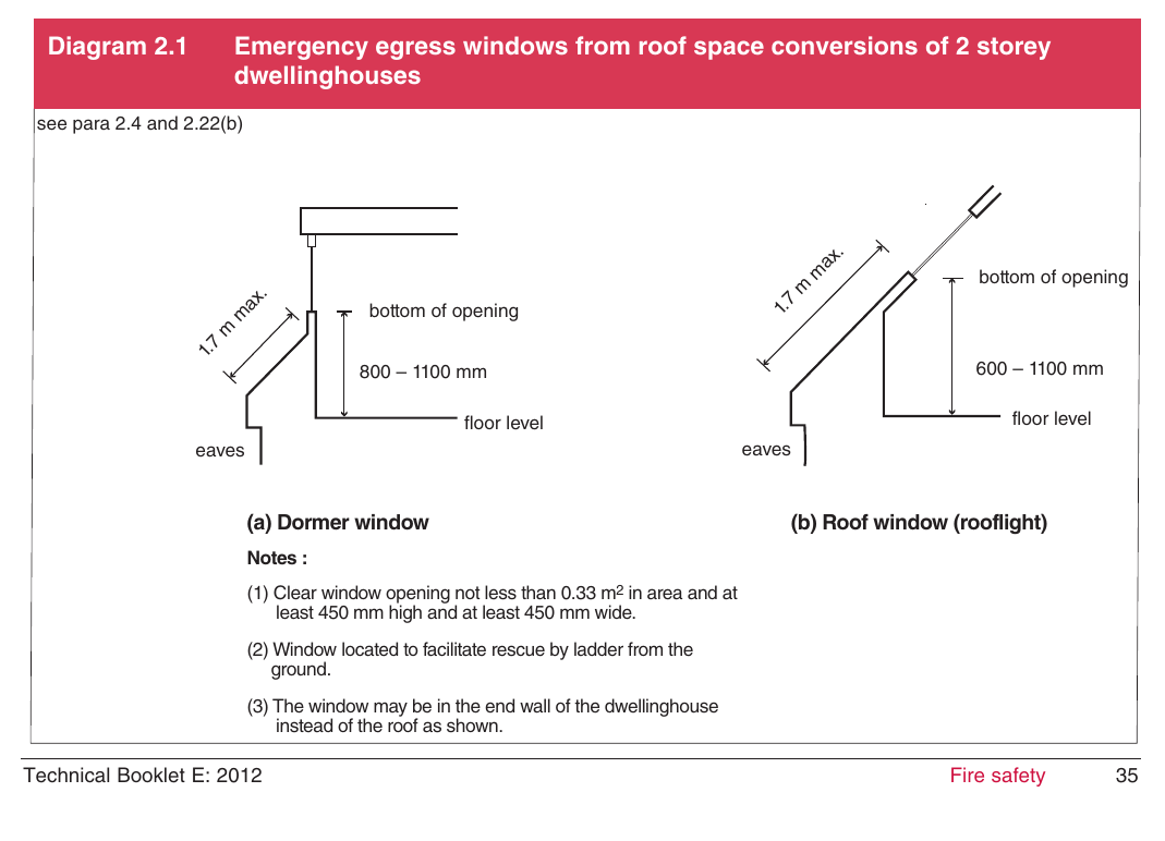
(b)where it is a dormer or roof window – be positioned as shown on Diagram 2.1;
(c)be located remote from the escape route; and
(d)comply with paragraph 2.9.
Where a basement storey contains a habitable room and does not have alternative escape routes it should be served by a protected stairway that extends to a final exit.
2.5Every habitable room, on an upper storey not more than 4.5 m above ground level that does not have alternative escape routes, should have an emergency egress window complying with paragraph 2.9 for escape purposes.
However, an emergency egress window may serve two such habitable rooms provided that –
(a)both rooms have their own access to the stairway enclosure; and
(b)it is possible to gain access, via a communicating door between the rooms, to the window without passing through the stairway enclosure.
2.6A habitable room should open directly onto a hallway (including a corridor or landing leading to the hallway) which leads to the entrance without passing through any room (except a porch), other than where the habitable room –
(a)has an alternative escape route;
(b)is on a storey not more than 4.5 m above ground level and the habitable room has an emergency egress window complying with paragraph 2.9; or
(c)is part of a roof space conversion which complies with paragraphs 2.17 to 2.22.
Diagram 2.1 Emergency egress windows from roof space conversions of 2 storey
Page 38
#Source page 38
Access rooms to inner rooms
2.7A habitable room may be an access room to any inner room. A kitchen should not be an access room to an inner room other than –
(a)to a utility room or conservatory which has an emergency egress window complying with paragraph 2.9; or
(b)where the kitchen and the inner room are on the same storey and the kitchen is part of an alternative escape route leading to its own final exit. See Diagram 2.2.
2.8Where a habitable room, by virtue of a stairway discharging into it, is an access room to a habitable room on the storey above –
(a)the upper storey should be not more than 4.5 m above ground level; and
(b)the foot of the stairway should be not more than 3 m from –
(i)a final exit; or
(ii)a door opening directly into a hallway (including a corridor leading to the hallway).
Emergency egress windows
2.9An emergency egress window should –
(a)have a clear opening that is not less than 0.33 m2 in area; and
(b)have a clear opening that is at least 450 mm high and at least 450 mm wide.
The lower edge of the window opening should be not less than 800 mm and not more than 1100 mm above the floor except in the case of a roof window where the lower edge of the window opening may be not less than 600 mm above the floor. For the purposes of this paragraph an emergency egress window should be taken to include a door which leads to an area (e.g. a balcony) from which a person could escape or be rescued. The minimum height to the lower edge of the opening should not apply to such a door.
2.10An emergency egress window should lead to a place that is free from the danger of fire and not lead to an enclosed yard or garden unless it has an area of relative safety which is not less than the height of the dwellinghouse from the dwellinghouse. An enclosed yard or garden is one from which there is no exit under the control of the occupants of the dwellinghouse.
Sleeping galleries
2.11Where a gallery for sleeping purposes is provided –
(a)the gallery should be not more than 4.5 m above ground level;
(b)the distance between the foot of the access stair to the gallery and the door to the room containing the gallery should be not more than 3 m;
(c)the floor area of the gallery should be not more than 30 m2;
(d)an alternative escape route, or an emergency egress window which complies with paragraph 2.9 located remote from the access stair, should be provided where the distance from the head of the access stair to any point on the gallery is more than 7.5 m; and
Page 39
#Source page 39
(e)any cooking facilities within the room containing the gallery should either –
(i)be enclosed with fire-resisting construction; or
(ii)be remote from the stair to the gallery and be positioned so that they do not prejudice the means of escape from the gallery.
Diagram 2.2 Kitchen as access room
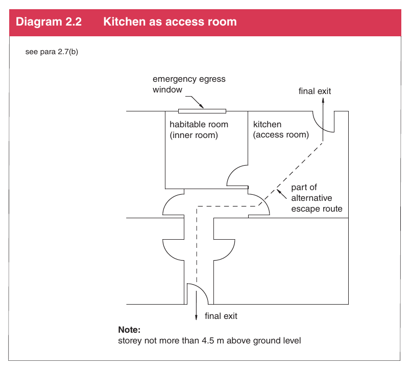
Provisions additional to the common provisions for a dwellinghouse with one storey more than 4.5 m above ground level
2.12In a dwellinghouse with only one storey more than 4.5 m above ground level –
(a)the top storey should –
(i)be separated from the lower storeys by fire-resisting construction; and
(ii)have an alternative escape route leading to its own final exit; or
(b)all storeys above the storey containing the final exit should be served by a protected stairway which either –
(i)extends to a final exit as shown in Diagram 2.3(a); or
(ii)leads to at least two escape routes at ground level, each leading to a final exit and separated from each other by fire-resisting construction and self-closing fire doors as shown in Diagram 2.3(b).
Page 40
#Source page 40
2.13Where the storey which is more than 4.5 m above ground level is created by the conversion of the roof space of a two storey dwellinghouse the provisions of paragraphs 2.17 to 2.22 may be applied as an alternative to the provisions of paragraph 2.12.
Provisions additional to the common provisions for a dwellinghouse with two or more storeys more than 4.5 m above ground level
2.14In a dwellinghouse with two or more storeys more than 4.5 m above ground level –
(a)all storeys above the storey containing the final exit should be served by a protected stairway which complies with paragraph 2.12(b); and
(b)each storey that is over 7.5 m above ground level should have an alternative escape route leading to its own final exit. Where access to an alternative escape route is through the protected stairway, the protected stairway should be subdivided by fire-resisting construction at or about 7.5 m above ground level.
Diagram 2.3 Alternative arrangements forfinal exits
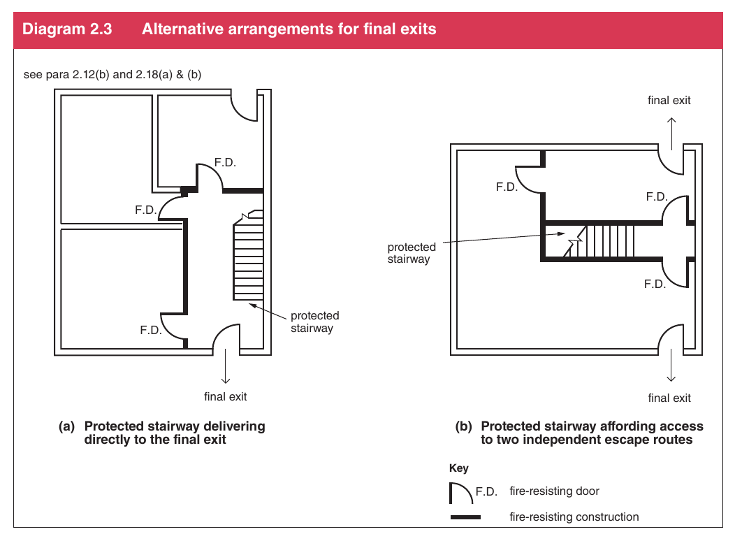
Page 41
#Source page 41
Ducted air circulation systems
2.15In a dwellinghouse with a storey more than 4.5 m above ground level, any system of ducted air circulation should –
(a)not be fitted with transfer grilles between any room and a protected stairway;
(b)not have supply and return grilles more than 450 mm above floor level;
(c)where air is ducted to a protected stairway – have the return air ducted back to the heater;
(d)where a duct passes through the enclosure to a protected stairway – have the joints between the duct and the enclosure fire-stopped; and
(e)where warm air heating is ducted – have a thermal cut out with maximum setting of 27ºC, which turns off the heater and any circulation fan if the ambient temperature exceeds that setting.
Passenger lifts
2.16Where a passenger lift is provided and serves a storey more than 4.5 m above ground level it should either –
(a)be located in the enclosure of a protected stairway; or
(b)be contained in a fire-resisting lift shaft.
Roof space conversions
2.17Where a roof space is to be converted to a habitable accommodation room or kitchen, an automatic fire detection and fire alarm in accordance with paragraph 2.23 and or 2.24 should be provided within the new habitable room or kitchen; the circulation spaces from the new room to the final exit; and to any habitable room or kitchen opening on to the circulation spaces leading from the new room to the final exit and either –
(a)the relevant provisions of paragraphs 2.4 to 2.15 should apply; or
(b)where the existing dwellinghouse has two storeys the provisions in paragraphs 2.18 to 2.22 may be followed provided that the new storey does not –
(i)exceed 50 m2 in floor area; or
(ii)contain more than two habitable rooms.
Note – The general provisions of this Section apply to any other roof space conversion which adds a new storey to an existing dwellinghouse.
Page 42
#Source page 42
Enclosure of existing stairway
2.18The existing stairway should be enclosed by fire-resisting walls and either –
(a)extend to a final exit as shown in Diagram 2.3(a); or
(b)lead to at least two escape routes at ground level, each delivering to a final exit and separated from each other by fire-resisting construction and self-closing fire doors as shown in Diagram 2.3(b).
2.19Any glazing (whether new or existing) in the enclosure of the existing stairway, other than to a bathroom or sanitary accommodation, should be fire-resisting. (See Tables 2.8, 4.1 and 4.2.)
2.20Other than where paragraph 2.18 requires a fire door, every doorway in the enclosure to the existing stairway should be fitted with an imperforate door. A door to a habitable room or a kitchen should be fitted with a self-closing device.
Where a new door is to be provided to an existing habitable room or kitchen it should be a fire door.
Fire separation of new storey
2.21The new storey should be separated from the rest of the dwellinghouse by fire-resisting construction. The new stairway should either –
(a)rise as a continuation of the existing stairway and enclosure, in which case the stairway should be separated from the new accommodation by fire-resisting construction; or
(b)be separated from the existing stairway and the rest of the dwellinghouse by fire-resisting construction.
Any door in new fire-resisting construction should be a self-closing fire door.
2.22Each habitable room in the new storey should have –
(a)an emergency egress window which complies with paragraph 2.9; or
(b)an emergency egress dormer window or roof window, of the size given in paragraph 2.9 positioned as shown in Diagram 2.1,
that is located to facilitate rescue from the ground by ladder.
However, an emergency egress window may serve both habitable rooms provided that –
(i)each room has its own access to the stairway enclosure; and
(ii)it is possible to gain access, via a communicating door between the rooms, to the window without passing through the stairway enclosure.
Page 43
#Source page 43
Automatic fire detection and fire alarm systems in dwellinghouses
2.23A dwellinghouse should be provided with either –
(a)smoke alarms complying with BS 5446-1 BS EN 14604 and a heat alarm or alarms complying with BS 5446-2 installed in accordance with paragraphs 2.25 to 2.33; or
(b)an automatic fire detection and fire alarm system complying with BS 5839-6 of at least Grade D2 Category LD2 standard including a smoke alarm or alarms in the principal every habitable room and a heat alarm or alarms in every kitchen.
Note 1 – A higher standard of protection should be considered where occupants of a proposed dwelling would be at special risk from fire. Further advice on this is also given in BS 5839-6.
Note 2 – BS 5446-1BS EN 14604 covers smoke alarms based on ionization chamber smoke detectors and optical smoke detectors. These different types of detector respond differently to smouldering and fast-flaming fires. Either type of detector is generally suitable. However, the choice of detector type should, if possible take into account the type of fire that might be expected and the need to avoid false alarms. Optical detectors tend to be less affected by low levels of ‘invisible’ particles, such as fumes from kitchens, that often cause false alarms. Accordingly, they are generally more suitable than ionization chamber detectors for installation in circulation spaces adjacent to kitchens.
Large dwellinghouses
2.24Where any storey in a dwellinghouse is more than 200 m2 in area the dwellinghouse should be provided with –
(a)where the number of storeys is not more than 3 – an automatic fire detection and fire alarm system complying with BS 5839-6 of at least Grade B A Category LD2 standard including a smoke detector or detectors in the principal every habitable room and a heat detector or detectors in every kitchen.; or
(b)where the number of storeys is more than 3 – an automatic fire detection and fire alarm system complying with BS 5839-6 of at least Grade A Category LD2 standard including a smoke detector or detectors in the principal habitable room and a heat detector or detectors in every kitchen.
Basement storeys should be counted in this provision.
Extensions and/or alterations
2.24A Where any new habitable room or kitchen is provided, an automatic fire detection and fire alarm system in accordance with paragraph 2.23 or 2.24 should be installed within the new habitable room or kitchen; the circulation spaces from the new room to the final exit; and to any habitable room or kitchen opening on to the circulation spaces leading from the new room to the final exit.
Page 44
#Source page 44
Provision of smoke alarms and heat alarms
2.25At least one smoke alarm should be provided –
(a)in the circulation route or routes on each storey; and
(b)in the principal every habitable room,
and at least one heat alarm should be provided in every kitchen. The smoke and heat alarms should be located to comply with the provisions of paragraphs 2.27 to 2.32.
Smoke alarms and heat alarms should be interconnected so that they all give an audible alarm when any one of them is activated. Radio linked interconnection between hard wired smoke alarms and/or heat alarms may be used. More detailed guidance for the use of radio linked technology can be obtained from BS 5839-6.
The maximum number of smoke alarms and heat alarms which may be interconnected should not exceed that given in the manufacturer’s instructions.
A back-up power source to each smoke alarm and heat alarm should be provided by either –
(i)a primary or secondary battery; or
(ii)a capacitor.
Installation of smoke alarms and heat alarms
2.26Smoke alarms and heat alarms should be permanently wired to either –
(a)a regularly used lighting circuit; or
(b)a circuit which –
(i)is separately fused at the distribution board;
(ii)serves only smoke alarms and heat alarms; and
(iii) where a residual current device is used – is not connected to a residual current device which is also used by any other circuit.
Smoke alarms and heat alarms may operate at a low voltage via a mains transformer. The cable for the power supply to, and interconnection of, the smoke alarms need not have special fire-survival properties.
2.27Smoke alarms should be located in the circulation route or routes of a dwellinghouse so that there is one –
(a)not more than 3 m from every bedroom door;
(b)not more than 7.5 m from every door to a living room or kitchen; and
(c)where a circulation route on a storey is more than 15 m long – not more than 15 m from another smoke alarm on the same circulation route and storey.
Page 45
#Source page 45
2.28Smoke alarms should be located in a principal every habitable room so that no point in the room is more than 7.5 m from the nearest smoke alarm. Heat alarms should be located in a kitchen so that no point in the kitchen is more than 5.3 m from the nearest heat alarm.
2.29A smoke alarm or heat alarm should be located so that it is –
(a)either on a ceiling and not less than 300 mm from a wall or light fitting, or where designed for wall mounting on a wall and not less than 150 mm, or more than 300 mm from the ceiling and the sensitive element should not be below the level of a door opening;
(b)not less than 300 mm from, and not directly above, a heater or an air conditioning ventilator;
(c)on a surface which is normally at the ambient temperature for the space it bounds; and
(d)easily and safely accessible.
2.30Where a smoke alarm is mounted on a ceiling, it should be located so that its sensitive element is not less than 25 mm or more than 600 mm below the ceiling.
2.31Where a heat alarm is mounted on a ceiling, it should be located so that its sensitive element is not less than 25 mm or more than 150 mm below the ceiling.
A heat alarm should not be located above a cooking appliance.
Note – The guidance given in this paragraph and paragraph 2.30 applies to ceilings that are predominately flat and horizontal.
2.32A smoke alarm should not be located in a kitchen, garage or other place where steam, condensation or fumes could give false alarms.
Note - A multi sensor alarm provides early warning of fire and can significantly reduce the amount of unwanted false alarms in certain circumstances. See BS 5839-6 for more detailed information.
2.33Where dwellinghouses are part of a sheltered dwelling scheme with a warden or supervisor, the fire detection and fire alarm system within each dwellinghouse should be connected to the warden’s or supervisor’s central monitoring point so as to –
(a)give an audible warning of the detection of smoke or heat in any dwellinghouse; and
(b)enable the identification of the dwellinghouse involved.
Flats
#Source page 46
Means of escape
2.34The means of escape in a flat should be in accordance with the relevant recommendations of BS 5588-1 BS 9991.
Smoke control in common escape routes
| 2.34A | The smoke control in common escape routes should be in accordance with the relevant recommendations of BS 9991 and the provisions in paragraphs 2.34B – 2.34D. |
| 2.34B | In a small building with a single stair, for an open plan flat layout design, the smoke control strategy should involve a common lobby approach. |
| 2.34C | Automatic opening vents to a smoke shaft should be a smoke damper product, tested and certified to BS EN 12101-8. Products tested as smoke rated fire doors are not acceptable replacements for smoke control dampers. |
| 2.34D | In a multiple stair building with a storey over 11 m above ground level, the corridor/lobby vents should activate automatically, as per the guidance for a single stair building. |
Automatic fire detection and fire alarm systems in flats
2.35Each individual flat should be provided with either –
(a)smoke alarms complying with BS 5446-1 BS EN 14604 and a heat alarm or alarms complying with BS 5446-2 installed in accordance with paragraphs 2.25 to 2.32; or
(b)an automatic fire detection and fire alarm system complying with BS 5839-6 of at least Grade D2 Category LD2 standard including a smoke alarm or alarms in the principal every habitable room and a heat alarm or alarms in every kitchen.
2.36Where any storey in a flat is more than 200 m2 in area, the flat should be provided with an automatic fire detection and fire alarm system complying with BS 5839-6 of at least Grade B A Category LD2 standard, including a smoke detector or detectors in the principal every habitable room and a heat detector or detectors in every kitchen.
Extensions and/or alterations
2.36A Where any new habitable room or kitchen is provided, an automatic fire detection and fire alarm system in accordance with paragraph 2.23 or 2.24 should be installed within the new habitable room or kitchen; the circulation spaces from the new room to the flat entrance door; and to any habitable room or kitchen opening on to the circulation spaces leading from the new room to the flat entrance door.
Buildings other than dwellings
#Source page 47
2.37In buildings other than dwellings the number of escape routes needed depends on the number of occupants (occupant capacity). In some cases a room or a storey is designed to accommodate a known number of people; in others the occupant capacity should be calculated by dividing the area of the room or storey (excluding stairways, lifts and sanitary accommodation) by the appropriate floor space factor given in Table 2.2. Where the occupant capacity is calculated for rooms the occupant capacity of a storey is the sum of the occupant capacities of the rooms on that storey. The occupant capacity of a building or part of a building is the sum of the occupant capacities of the storeys in that building or part.
2.38In buildings other than dwellings a suitable fire detection and fire alarm system to BS 5839-1 should be installed. The factors which have to be considered when assessing what category of fire detection and fire alarm system is to be provided will vary from one set of premises to another. Therefore the appropriate category will need to be considered on a case by case basis. Automatic detection should be provided where required by the provisions in this Section and in Sections 4 and 6.
Note – General guidance on the category of automatic fire detection that may need to be provided within a building can be found in Table A.1 of BS 5839-1.
2.39Where a building contains areas in different purpose groups the means of escape from any area which is of Purpose Group 1(a), 2 or 5 should be independent of the means of escape from other areas of the building.
Horizontal part of the escape route
2.40The provisions in paragraphs 2.41 to 2.59 relate to horizontal escape routes leading to storey exits. They are mainly concerned with providing more than one escape route (except in the circumstances described in paragraph 2.41), limiting the distance to be travelled, and ensuring that the routes are of adequate width.
Single escape routes
2.41Alternative escape routes should be provided from all parts of the building other than in the following circumstances where a single route is permitted –
(a)areas from which a storey exit can be reached within the maximum travel distance in one direction only given in Table 2.3, provided that no room in this situation has an occupant capacity of more than 60 people, or 30 people if the building is an Institution [Purpose Group 2(a)]; and
(b)a storey with an occupant capacity of no more than 60 people provided that a storey exit can be reached within the maximum travel distance in one direction only given in Table 2.3.
Page 48
#Source page 48
Travel distance
2.42Whether there are alternative escape routes or only a single one, the travel distance to the nearest storey exit should not exceed the maximum relevant travel distance given in Table 2.3.
Note – It is only the distance to the nearest storey exit that should be so limited. The distance from the same point in the storey to any other storey exit may be longer.
Where the initial part of an escape route is in one direction only and leads to a point from which escape is possible in two directions (e.g. as shown in Diagram 2.4), the initial part should not exceed the maximum travel distance in one direction only, and the overall travel distance should not exceed the maximum travel distance in more than one direction.
Number of escape routes and exits
2.43The number of escape routes and exits should be not less than the number given in Table 2.1 for the relevant occupant capacity of the room or storey as appropriate. The escape routes and exits should be arranged such that the travel distances given in Table 2.3 are not exceeded.
| Table 2.1 Minimum number of escape routes and exits from a room or storey | |
|---|---|
| Maximum occupant capacity | Minimum number of escape routes/exits |
| 60 | 1(1) |
| 600 | 2 |
| 1000 | 3 |
| 2000 | 4 |
| 4000 | 5 |
| 7000 | 6 |
| 11000 | 7 |
| 16000 | 8 |
| More than 16000 | 8(2) |
| Notes: (1) See paragraph 2.41 for the circumstances in which single exits and escape routes are acceptable. (2) Plus 1 per 5000 people (or part thereof) over 16000. |
Page 49
#Source page 49
Table 2.2 Floor space factors
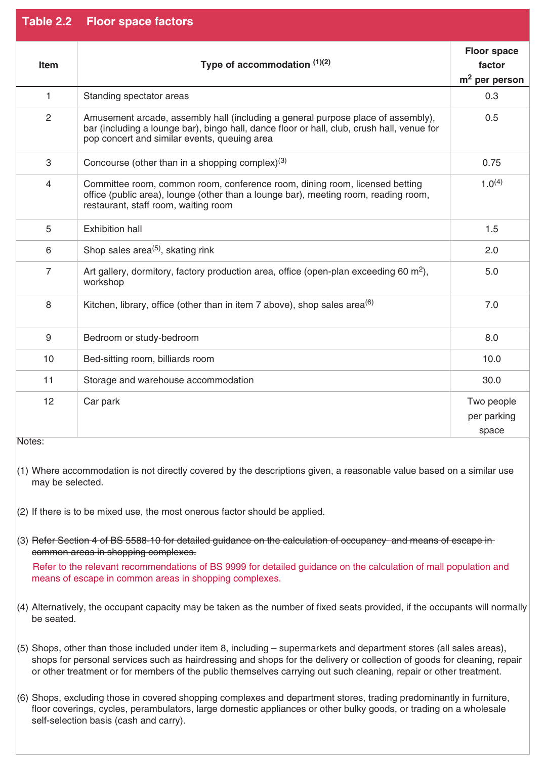
Page 50
#Source page 50
Table 2.3 Limitations on travel distances
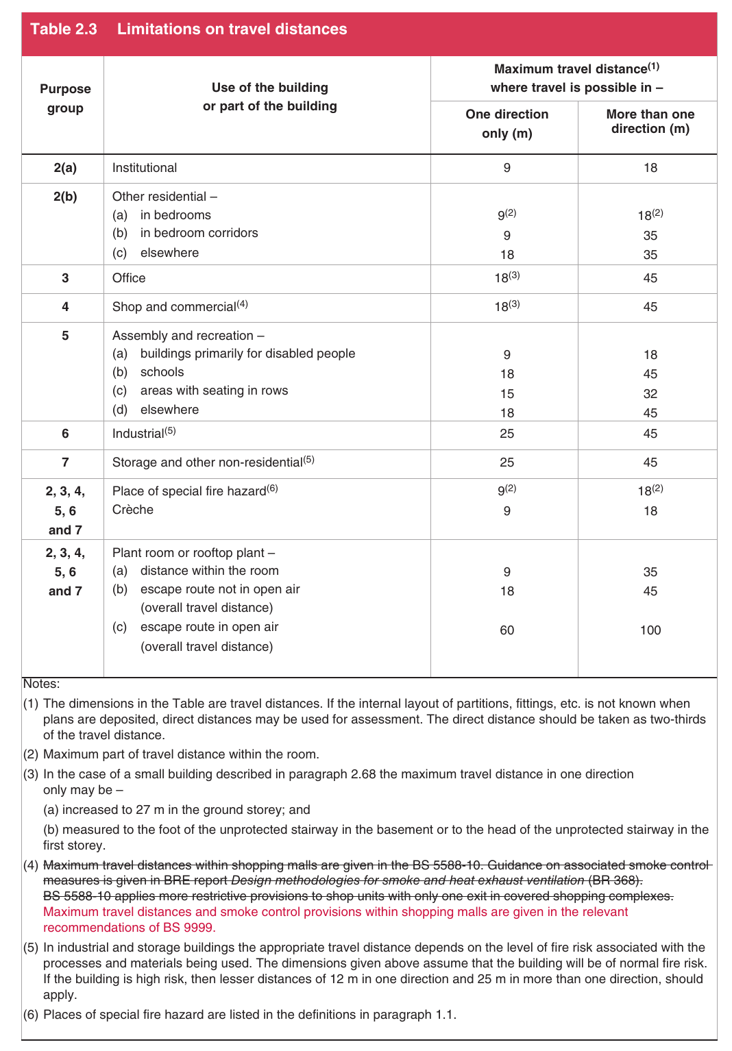
Page 51
#Source page 51
Diagram 2.4 Travel distance in single direction leading to alternative escape routes
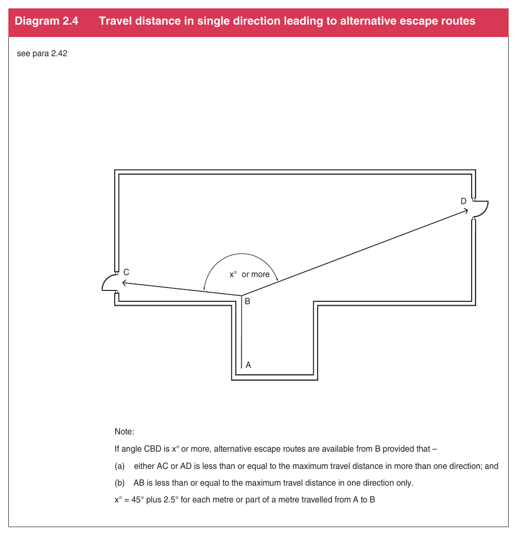
Page 52
#Source page 52
Alternative escape routes
2.44To prevent alternative escape routes being simultaneously unusable they should either –
(a)be 45º or more apart (see Diagram 2.5); or
(b)if less than 45º apart be separated from each other by fire-resisting construction.
Diagram 2.5 Alternative escape routes
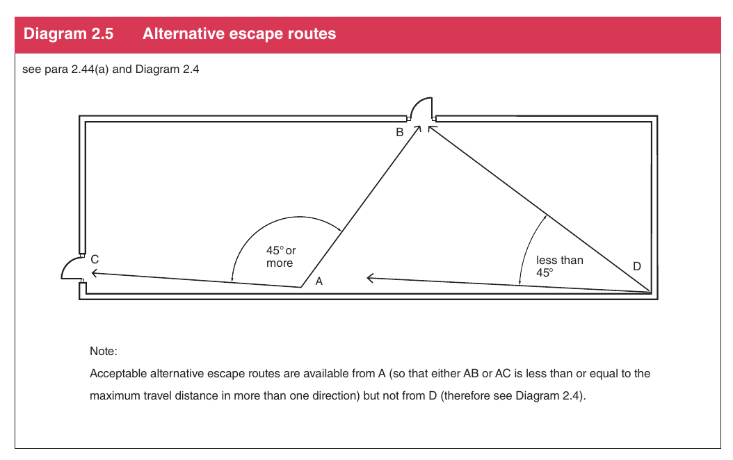
Note: Acceptable alternative escape routes are available from A (so that either AB or AC is less than or equal to the maximum travel distance in more than one direction) but not from D (therefore see Diagram 2.4).
Page 53
#Source page 53
Inner rooms
2.45An inner room is only permitted where –
(a)the number of occupants of the inner room is not more than 60 people (or in the case of a building in Purpose Group 2(a), 30 people);
(b)it is not a bedroom;
(c)the escape route from the inner room does not pass through more than one access room;
(d)the distance from any point in the inner room to the nearest exit from the access room does not exceed the appropriate maximum travel distance in one direction only given in Table 2.3;
(e)the access room is not a place of special fire hazard and is in the control of the same occupier as the inner room; and
(f)one of the following applies –
(i)that part of the enclosure separating the inner and access room is stopped at least 500 mm below the ceiling;
(ii)a vision panel of not less than 0.1 m2 is provided in the enclosure to the inner room so that a fire in the access room will be visible from the inner room at an early stage; or
(iii) the access room is fitted with a suitable automatic detection and alarm system to warn the occupants of the inner room of the outbreak of a fire in the access room.
See Diagram 2.6.
Diagram 2.6 Inner rooms and access rooms
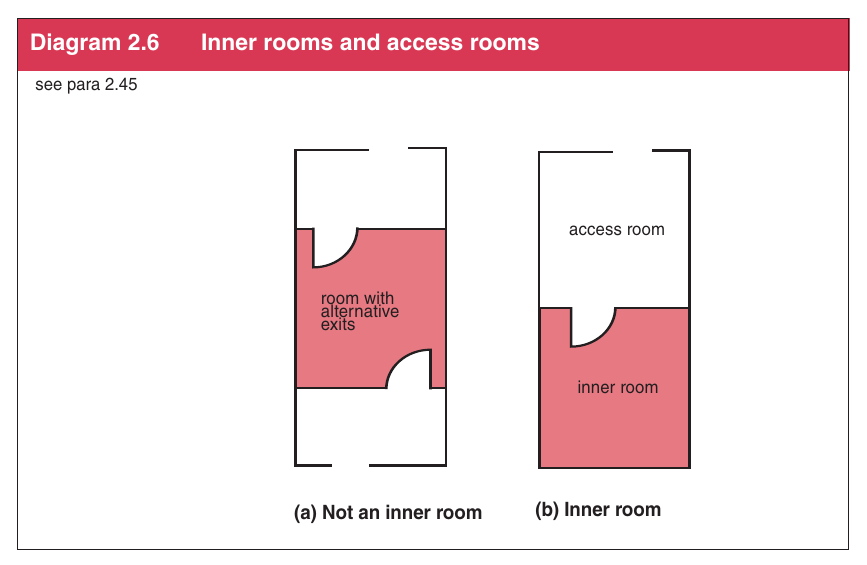
Page 54
#Source page 54
Crèches
2.46Where a building has an ancillary use for child care the accommodation for children should be located in the ground storey adjacent to an external wall and should have not less than two exits, one of which should be a final exit.
However, where location on the ground storey is not possible it should be located as near ground level as possible provided that –
(a)it is adjacent to an external wall and it has not less than two exits, one of which should be a storey exit;
(b)it is not located above the level at which the parents or guardians are accommodated unless their escape route is through the upper level; and
(c)it is not located on a basement storey unless it has an open side and a final exit at ground level.
Access to storey exits
2.47In any storey which has more than one escape stairway the escape routes should be arranged so that people do not have to pass through one stairway to reach another. However, it is acceptable to pass through the protected lobby of one stairway to reach another escape stairway.
Open spatial planning
2.48Escape routes should not be prejudiced by open connections between floors such as at an escalator.
An escape route should not be within 5 m of the open connection unless –
(a)the direction of travel is away from the opening; or
(b)there is an alternative escape route which does not pass within 5 m of the open connection.
See Diagram 2.7.
Planning of storey exits in a central core
2.49A building with more than one storey exit in a central core should be planned so that the storey exits are remote from each other and not linked by a lift hall, lobby, or undivided corridor.
Where the central core is separated from the accommodation by a corridor, the corridor should be subdivided by self-closing fire doors (and any necessary associated screens) so that the storey exits are separated as in Diagram 2.8.
Page 55
#Source page 55
Diagram 2.7 Escape routes in relation to open connections between floors
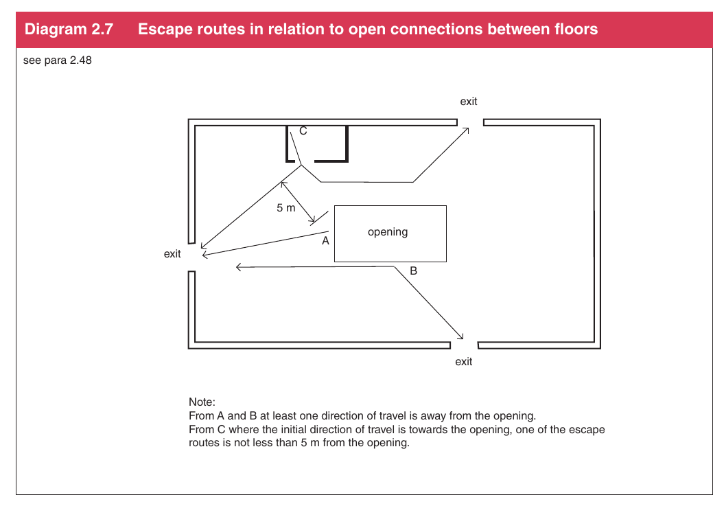
Diagram 2.8 Storey exits in a central core
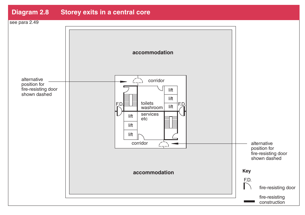
Page 56
#Source page 56
Storeys divided into different uses
2.50Where a storey has an ancillary use for the consumption of food or drink by customers, the area given over to that use should –
(a)have not less than two escape routes; and
(b)have escape routes that lead directly to a storey exit without entering a kitchen or place of special fire hazard.
Storeys divided into different occupancies
2.51Where a storey is divided into two or more occupancies (i.e. ownerships, tenancies or similar) the means of escape from one occupancy should not pass through any other occupancy.
However, where the means of escape includes a corridor common to two or more occupancies then either it should be a protected corridor, or a fire detection and fire alarm system to BS 5839-1, of at least Category L3 standard, should be installed.
Width of escape routes and storey exits
2.52The width of an escape route or storey exit should be not less than the minimum width given in Table 2.4, for the appropriate number of people assessed as being likely to use it. There should be no projections into escape routes other than handrails with a projection of less than 100 mm and stringers, skirtings and architraves of less than 30 mm, on either or both sides. (Note – for the purposes of Part H stair widths are measured between handrails.) The width of a storey exit should be measured in accordance with B1(g) of Appendix B.
| Table 2.4 Widths of escape routes and storey exits | |
|---|---|
| Maximum number of people(1) | Minimum width(2)(3) mm |
| 50 | 750(4) |
| 110 | 850 |
| 220 | 1100 |
| More than 220 | 5 per person(5) |
| Notes: (1) Assessed as being likely to use the escape route or storey exit. (2) In schools the minimum width of corridors in pupil areas should be 1050 mm where escape is in more than one direction and 1600 mm where escape is in one direction only. (3) Part R may require greater widths. (4) May be reduced to 530 mm for gangways between fixed storage racking, other than in public areas in Purpose Group 4 buildings. (5) 5 mm per person does not apply to an opening serving less than 220 persons. |
Page 57
#Source page 57
Where there is a single escape route and storey exit their capacity should be not less than the number of occupants of the storey.
Where two or more escape routes and storey exits are provided it should be assumed that one of them may not be available due to fire or smoke. Therefore, each storey exit in turn should be discounted in order to ensure that the capacity of the remaining storey exits is adequate for the total number of people needing to use them. [This may have implications for the width of stairs because they should be not less than the width of any storey exit leading onto them – see paragraph 2.63(b)].
2.53The total number of persons which two or more available storey exits (after discounting) can accommodate is found by adding the maximum number of persons determined for each storey exit width. For example in Table 2.4 three available exits each 850 mm wide will accommodate 110 x 3 = 330 persons (not the 510 persons accommodated by a combined exit width of 2550 mm).
Separation of circulation routes from escape stairways
2.54A protected stairway should not form part of the primary circulation route between different parts of the building at the same level. However, it is acceptable for a protected lobby to form part of the primary circulation route.
Protected corridors
2.55A corridor that is part of the means of escape should be a protected corridor where it is –
(a)a corridor serving one or more bedrooms;
(b)a corridor from which escape is in one direction only (i.e. a dead end corridor); or
(c)common to two or more different occupancies other than where a fire detection and alarm system is installed in accordance with paragraph 2.51.
Subdivision of corridors
2.56Where a corridor exceeding 12 m in length connects two or more storey exits, it should be subdivided by self-closing fire doors (and any necessary associated fire-resisting screens) approximately mid-way between the storey exits so that no undivided part is common to two or more storey exits. This is to reduce the likelyhood of smoke making alternative routes impassible before all occupants have escaped. For corridors around a central core see paragraph 2.49.
Where a dead end portion of a corridor exceeding 4.5 m in length leads to a point where alternative escape routes are available, the dead end portion should be extended and separated by self-closing fire doors (and any necessary associated fire-resisting screens) from the remainder of the corridor as shown in Diagram 2.9. However, where the stairways and corridors are protected by a pressurization system complying with BS EN 12101-6, such separation is not necessary.
Page 58
#Source page 58
Diagram 2.9 Dead end corridors
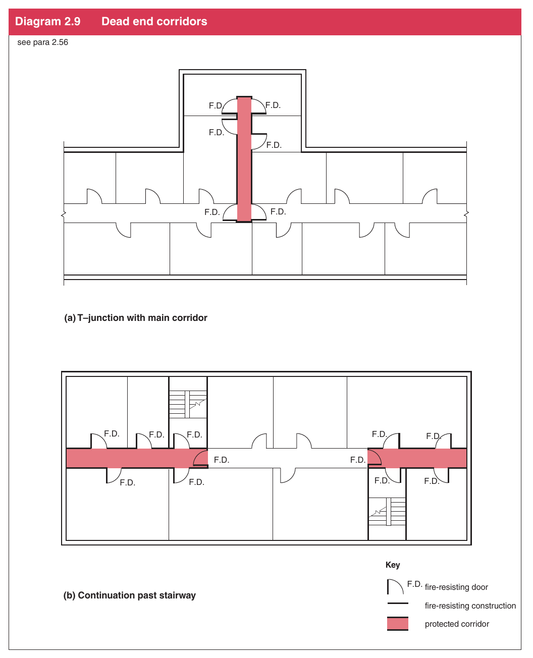
Page 59
#Source page 59
Enclosure of corridors that are not protected corridors
2.57Where a corridor which is part of an escape route, but is not a protected corridor, is enclosed by partitions, those partitions provide some defence against the spread of smoke in the early stages of a fire and should be carried up to the underside of the structural floor or to a suspended ceiling. In the latter case cavity barriers should be provided in accordance with paragraph 4.35. Every opening into a room should be fitted with a door which need not be a fire door.
External escape routes
2.58Where an external escape route, other than a stair, is beside an external wall of the building, that part of the external wall within 1.8 m (measured horizontally) of the escape route should be of fire-resisting construction 1.1 m above and 9 m below the level of the route as shown in Diagram 2.11 (see page 61).
Escape over flat roofs
2.59Where more than one escape route is available from a storey, (or part of a building where appropriate) one of those routes may be by way of a flat roof, provided that –
(a)the route does not serve –
(i)a building of Purpose Group 2(a); or
(ii)in a building of any other purpose group – an area intended for use by members of the public;
(b)the flat roof is part of the same building from which escape is being made;
(c)the route across the flat roof leads to a storey exit or external escape route;
(d)the part of the flat roof forming the escape route and its supporting structure, together with any opening in the roof within 3 m of the escape route, is fire-resisting; and
(e)the route is defined and guarded by walls and/or protective barriers which comply with Part H.
Page 60
#Source page 60
Vertical part of the escape route
2.60The provisions in paragraphs 2.61 to 2.76 relate to the vertical escape down or up escape stairways towards a final exit. They are mainly concerned with providing a sufficient number of escape stairs of adequate aggregate width and their protection.
Number of escape stairways
2.61The number of escape stairways in a building, or part of a building is determined by the provisions in –
(a)paragraph 2.39 regarding independent escape routes from areas in certain uses;
(b)paragraphs 2.41 and 2.43 regarding the design of the horizontal part of the escape route;
(c)paragraphs 2.63 and 2.64 regarding the width of stairs and the discounting of a stairway respectively; and
(d)Section 6 regarding the provision and location of firefighting stairways.
Single escape stairways
2.62Where independent escape routes are not required from areas in different purpose groups, in accordance with paragraph 2.39, a single escape stairway may serve –
(a)a basement which is permitted to have a single escape route in accordance with paragraph 2.41; or
(b)a building which has no storey with a floor level more than 11 m above ground level, and in which every storey is permitted to have a single escape route in accordance with paragraph 2.41.
Width of escape stairs
2.63An escape stair should be wide enough to accommodate the appropriate number of people assessed as being likely to use it.
This width depends on the number of stairways provided and whether the escape strategy is based on simultaneous evacuation (see paragraph 2.65) or phased evacuation (see paragraph 2.66).
In any event an escape stair should –
(a)be not less than the appropriate dimension given in Table 2.5;
(b)be not less than the width required for any storey exit giving access to it;
(c)not reduce in width at any point on its way to the final exit; and
(d)not exceed 1400 mm if the vertical extent of the escape stair is more than 30 m, unless it is at least 1800 mm and it is provided with a central handrail. In such a case the width on each side of the handrail should be considered separately for the purpose of assessing stair capacity. (Research indicates that people prefer to stay within reach of a handrail when making a prolonged descent, consequently the centre part of a wide stair is little used and could be hazardous).
Page 61
#Source page 61
Table 2.5 Minimum width of escape stairs
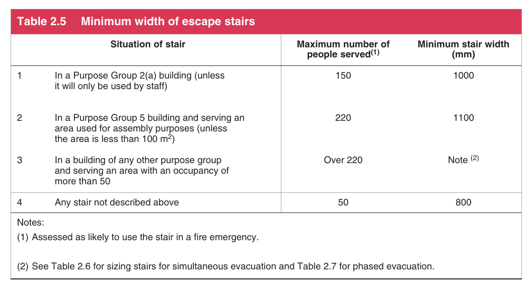
Discounting of escape stairways
2.64Whether simultaneous or phased evacuation is used, where two or more escape stairways are provided it should be assumed that one of them may not be available due to fire or smoke. Therefore, each stairway in turn should be discounted in order to ensure that the capacity of the remaining stairways is adequate for the total number of people needing to use them.
This discounting provision need not be applied where –
(a)the escape stairways are approached on each storey (except the topmost storey), through a protected lobby; or
(b)the escape stairways are protected by pressurization systems designed in accordance with BS EN 12101-6,
however, discounting storey exits still needs to be considered (see paragraph 2.52).
Simultaneous evacuation
2.65In a building or part of a building designed for simultaneous evacuation the escape stairways should have the capacity to allow all floors to be evacuated simultaneously and a suitable fire detection and fire alarm system to BS 5839-1, should be installed.
Simultaneous evacuation should be used for –
(a)a basement;
(b)a building containing open spatial planning;
(c)a building of Purpose Group 2; and
(d)a building of Purpose Group 5.
Page 62
#Source page 62
Where simultaneous evacuation is to be used the capacity of an escape stairway should be either –
(i)in a building of not more than 10 storeys and for basements – that given for the appropriate width of escape stairs in Table 2.6; or
(ii)in a building of more than 10 storeys – that derived from the formula – P = 200w + 50(w – 0.3)(n – 1) for stairs not less than 1100 mm wide, where P = the number of people that can be accommodated; w = the width of the escape stair (in metres); and n = the number of storeys served by the stair.
Table 2.6 Capacity of escape stairways for simultaneous evacuation
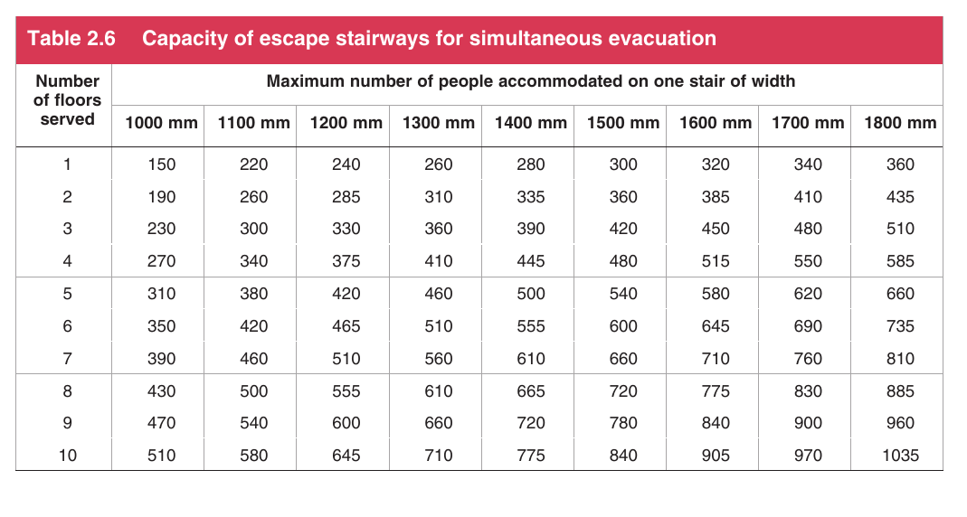
Page 63
#Source page 63
Worked examples
A building comprises 12 storeys of offices (ground + 11). What is the minimum width needed for the stairs serving the office floors with a population of 1200 people (excluding the ground floor population which does not use the stairs), using simultaneous evacuation? Two stairs satisfy the travel distance limitations.
(a) The population is distributed evenly. As the top office storey is at a height greater than 18 m, both stairs need added protection (see paragraph 2.69). Therefore, if both stairs are entered at each level via a protected lobby, then both stairs can be assumed to be available (see paragraph 2.64). P = 1200/2 = 600, n = 11 From the formula –
600= 200w + 50(w - 0.3)(11 - 1) 600 = 200w + (50w - 15)(10) 600 = 200w + 500w - 150 750 = 700w w = 1.07 m (1070 mm)
Therefore, both stairs should be at least 1070 mm wide. But this needs to be increased to 1100 mm as the formula applies to stairs 1100 mm or wider (see paragraph 2.65).
This width should also be adequate to comply with paragraph 2.63 when one storey exit is discounted in accordance with paragraph 2.52
(i.e. the stair widths are not less than the minimum widths needed for 109 people in Table 2.4).
(b) The population is not distributed evenly (e.g. 1000 people occupy floors 1 to 9, and 200 occupy floors 10 to 11).
As the top office storey is at a height greater than 18 m, both stairs need added protection (see paragraph 2.69). If both stairs are entered at each level via a protected lobby, then both stairs can be assumed to be available (see paragraph 2.64).
(i) To find the width of the stairs serving floors 10 to 11 – P = 200/2 = 100, n = 2 From the formula –
100= 200w + 50(w - 0.3)(2 - 1) 100 = 200w + (50w - 15)(1) 100 = 200w + 50w - 15 115 = 250w w = 0.46 m (460 mm)
Therefore, both stairs between the 9th floor landing and the top floor should be at least 460 mm. But this needs to be increased to 1100 mm as the formula applies to stairs 1100 mm or wider (see paragraph 2.65).
Page 64
#Source page 64
This width should also be adequate to comply with paragraph 2.63 when one storey exit is discounted in accordance with paragraph 2.52
(i.e. the stair widths are not less than the minimum widths needed for 100 people in Table 2.4).
(ii) To find the width of the stairs serving floors 1 to 9 – P = 1200/2 = 600, n = 9 From the formula:
600= 200w + 50 (w - 0.3) (9 - 1) 600 = 200w + (50w - 15) (8) 600 = 200w + 400w - 120 720 = 600w w = 1.20 m (1200 mm)
Therefore, both stairs between the 9th floor landing and the ground floor should be at least 1200 mm wide. This width should also be adequate to comply with paragraph 2.63 when one storey exit is discounted in accordance with paragraph 2.52
(i.e. the stair widths are not less than the minimum widths needed for 111 people in Table 2.4).
Phased evacuation
2.66In certain buildings it may be advantageous to design the escape stairways on the concept of phased evacuation. With phased evacuation the first people to be evacuated are those on the floor of the fire and the floor above together with those in the building who have reduced mobility.
Subsequently, if there is a need to evacuate more people, it should be done two floors at a time.
In such a building, or part of a building –
(a)every escape stairway should be approached through a protected lobby or protected corridor at each storey, other than at a top storey consisting exclusively of plant rooms;
(b)a protected lobby at each storey should be provided to the approach to every lift that is not within the enclosure of a protected stairway other than at a top storey consisting exclusively of plant rooms;
(c)every floor should be a compartment floor;
(d)an automatic sprinkler system complying with the relevant recommendations of BS 5306-2 or BS EN 12845, should be installed in accordance with Section 8 throughout the building where the building has a storey more than 30 m above ground level;
(e)an automatic fire detection and fire alarm system, to BS 5839-1, of at least Category L3 standard, should be installed;
(f)a voice alarm system to BS 5839-8 should be installed throughout the building, or part of the building; and
(g)an emergency voice communication system to BS 5839-9 should be installed with a master station at fire and rescue access level (see Section 6) and an outstation on every storey.
Page 65
#Source page 65
The minimum width of a stair for phased evacuation should be that given in Table 2.7 for the appropriate maximum number of people on the most heavily occupied storey.
Worked example
A building comprises 12 storeys of offices (ground + 11). What is the minimum width needed for the stairs serving the office floors with a population of 1200 people (excluding the ground floor population which does not use the stairs), using phased evacuation? Two stairs satisfy the travel distance limitations.
As the top office storey is at a height greater than 18 m, both stairs need added protection (see paragraph 2.69). Therefore if both stairs are entered at each level via a protected lobby, then both stairs can be assumed to be available (see paragraph 2.64).
The population is divided equally therefore –
The number of people per storey is (1200/11) = 109.
Each stair must be able to accommodate half the maximum number of people in each storey (109/2) = 55 people.
From Table 2.7 the width of 1 stair to accommodate 55 people is 1000 mm (maximum capacity 100 people).
Both stairs need to be not less than 1000 mm wide.
This width will also be adequate when one storey exit is discounted in accordance with paragraph 2.52 and the consequent need to comply with paragraph 2.63 (i.e. the stair widths are not less than the minimum widths needed for people in Table 2.4).
| Table 2.7 Minimum width of escape stairs for phased evacuation | |
|---|---|
| Maximum number of people in any storey(1) | Stair width(2) (mm) |
| 100 | 1000 |
| 120 | 1100 |
| 130 | 1200 |
| 140 | 1300 |
| 150 | 1400 |
| 160 | 1500 |
| 170 | 1600 |
| 180 | 1700 |
| 190 | 1800 |
| Notes: (1) Where the number of people (P) on the most heavily occupied storey is more than 190, the minimum width of the escape stair (W mm) should be calculated from W = (P x 10) – 100. (2) Where the stair serves a storey more than 30 m above ground level the width should not exceed 1400 mm [see paragraph 2.63(d)]. |
Page 66
#Source page 66
Protection of escape stairways
2.67An escape stairway requires protection in order that it may provide an area of relative safety during a fire evacuation. The provisions for protecting an internal escape stairway are given in paragraphs 2.69 to 2.73 and further provisions apply when an escape stairway penetrates a compartment floor (see paragraph 4.23) or is a firefighting stairway (see paragraphs 6.3 to 6.6).
An accommodation stairway may form part of an internal route to a storey exit or final exit provided that the travel distance complies with paragraph
2.42and the number of people involved is low.
2.68An unprotected stairway may be used as an escape stairway in a small building provided that –
(a)the building is of Purpose Group 3 or 4 and is not used for bar or restaurant purposes;
(b)the building is designed for single occupancy;
(c)the building comprises not more than a basement, ground and first storey;
(d)the floor area of any storey is not more than 90 m2;
(e)the stair does not connect more than two storeys; and
(f)the stair discharges not more than 3 m from a final exit.
Protected lobbies and protected corridors
2.69A protected lobby or protected corridor should be provided to every escape stairway on every storey in a building other than the top storey where –
(a)the escape stairway is the only escape stairway serving the building (or part of the building) and the building (or part of the building) has more than one storey above or more than one storey below the storey containing the final exit from the escape stairway;
(b)the escape stairway serves a storey more than 18 m above ground level;
(c)the building is designed for phased evacuation and the top storey consists exclusively of plant rooms; or
(d)the discounting stairway provisions have not been used in calculating escape stair widths as permitted by paragraph 2.64.
A protected lobby should also be provided between an escape stairway and a place of special fire hazard, and that lobby should have either not less than 0.4 m2 of permanent ventilation or be protected from the ingress of smoke by a mechanical smoke control system.
Page 67
#Source page 67
Exits from protected stairways
2.70Every protected stairway should discharge either –
(a)directly to a final exit; or
(b)to a protected exit passageway leading only to a final exit. Where the stairway is lobbied, any door openings in the walls enclosing the protected exit passageway should be similarly lobbied.
Where the escape route from an escape stairway also forms the escape route from the ground and/or basement storey its width should be increased accordingly.
Separation of adjoining protected stairways and protected exit passageways
2.71Where two or more protected stairways or protected exit passageways adjoin they should be separated by an imperforate enclosure.
Use of space within protected stairways
2.72A protected stairway, other than a firefighting stairway (see Section 6), should not contain any accommodation or services other than –
(a)sanitary accommodation or wash rooms provided that they are not used as a cloakroom;
(b)a lift, provided that in a building (or part of a building) with a single escape stairway the lift motor room is over the lift shaft or outside the protected stairway; and
(c)where it is not the only protected stairway in a building (or part of a building) –
(i)a reception desk or enquiry office area having an area of not more than 10 m2 and located at ground or access level; or
(ii)a cupboard formed by fire-resisting construction.
Basement stairways
2.73Where an escape stairway forms part of the only escape route from an upper storey of a building (or part of a building) it should not serve a basement storey.
Where there is more than one escape stairway from an upper storey of a building (or part of a building) at least one should terminate at ground storey level. Other stairways may connect to a basement storey provided that they are protected at each basement level by a protected lobby or protected corridor.
Page 68
#Source page 68
External walls adjacent to protected stairways
2.74Where a protected stairway projects beyond, is recessed from, or is in an internal angle of the external walls of the building – the distance between any unprotected areas (see Section 5) in the adjacent external walls of the building and an unprotected area in the external walls of the protected stairway should not be less than 1.8 m, as shown in Diagram 2.10.
External escape stairs
2.75Where more than one escape route is available from a storey (or part of a building), one or more than one, of those routes may be by way of an external escape stair provided that –
(a)there is at least one internal escape stairway from every part of each storey; and
(b)in the case of –
(i)a building of Purpose Group 5 – the route is not intended for use by members of the public; or
(ii)a building of Purpose Group 2 – the route serves only staff accommodation (office or residential).
Diagram 2.10 External walls adjacent to protected stairways
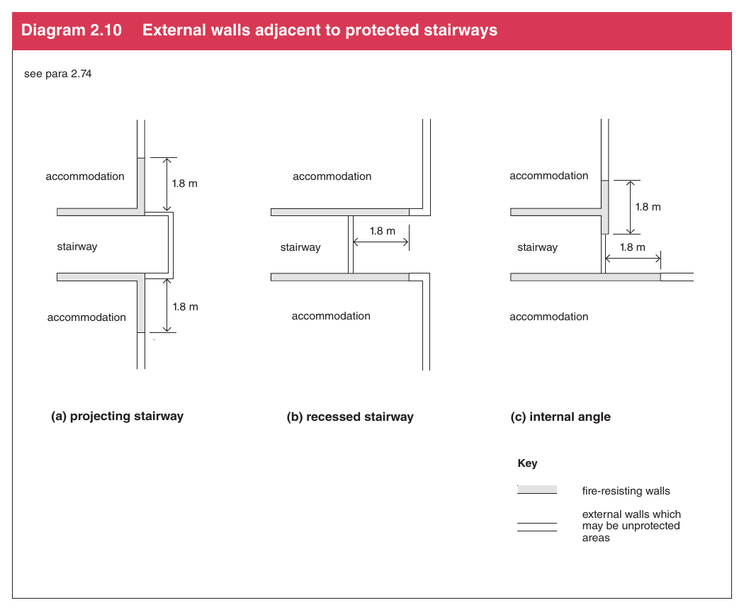
Page 69
#Source page 69
2.76Where an external stair is part of an escape route –
(a)the stair should be protected from the weather when it serves a floor or flat roof more than 6 m above ground level. The degree of protection from the weather will depend on the exposure of the stair;
(b)all doors giving access to the stair should be fire-resisting except at the top of any stair which leads downwards;
(c)any part of the external walls within 1.8 m of the stair (measured horizontally) should be of fire-resisting construction –
(i)1.8 m above (this may be reduced to 1.1 m at the top landing of the stair provided that it is not the top landing of a basement stair);
(ii)1.8 m at the side of; and
(iii)9 m below, the flights and landings of the stair as shown on Diagram 2.11;
(d)the external walls of the building within 1.8 m of the escape route from the bottom of the stair should be fire-resisting to a height of
1.1m above the escape route; and
(e)glazing in fire-resisting external walls described in (c) and (d) above should also be fire-resisting and fixed shut (see Table 2.8 for the limitations on the use of uninsulated glazing).
Page 70
#Source page 70
Diagram 2.11 Fire resistance of external walls adjacent to external escape routes see para 2.58 and 2.76 the 1.8 m zone above the top landing of the stair may be reduced to 1.1 m provided that the top landing is not part of a basement stair door – no fire resistance window – 30 minutes fire resistance required 1.8 m fixed shut 1.8 m
1.8m
9m
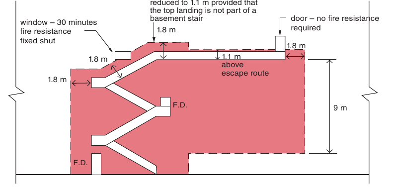
Example A
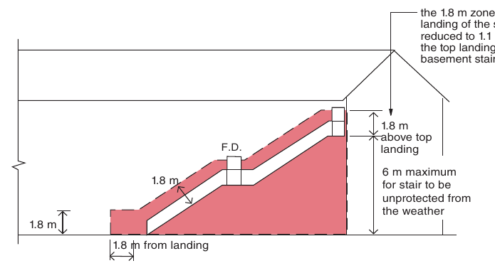
elevation b1 elevation a the 1.8 m zone above the top landing of the stair may be reduced to 1.1 m provided that the top landing is not part of a basement stair
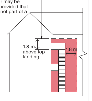
elevation b2
1.8m
Key
F.D. fire-resisting door plan fire-resisting area of wall
Example B
1.8m
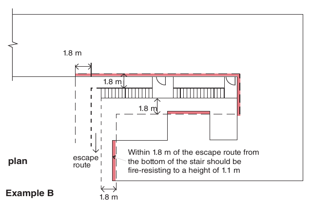
Page 71
#Source page 71
Table 2.8 Limitations on the use of uninsu on escape routeslated glazing in enclosures and fire doors
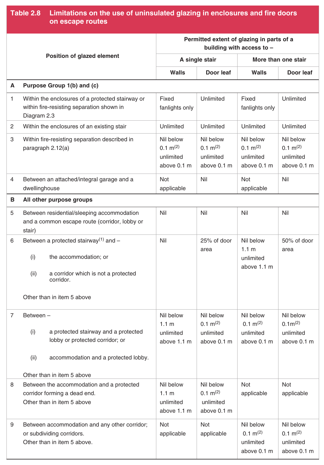
Page 72
#Source page 72
Table 2.8 Limitations on the use of uninsulated glazing in enclosures and fire doors on escape routes (cont’d)
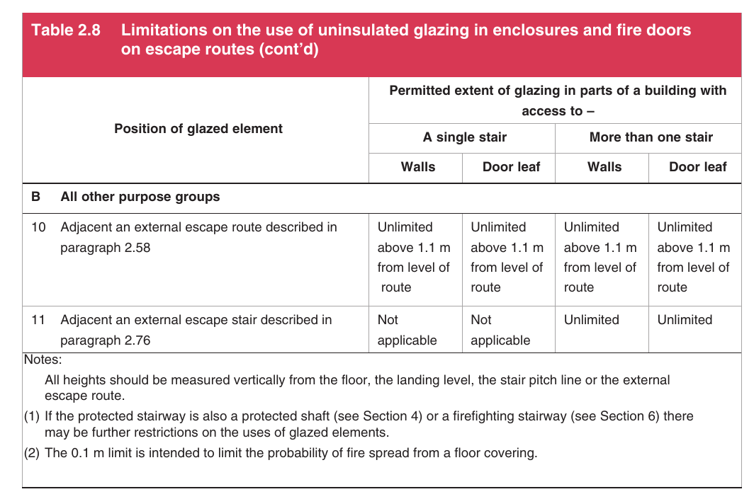
Provision of refuges
2.77Refuges are relatively safe areas for disabled people, with a disability or other impairment which may slow or restrict their ability to exit, to wait for short periods before completing their evacuation. They are not areas where disabled people should be left to wait for rescue by the Fire and Rescue Service, or to wait until the fire is extinguished.
A refuge should be provided for each protected stairway affording egress from each storey, except storeys consisting exclusively of plant rooms. A refuge should also be provided at each final exit that leads unto an external flight of steps (in this case the refuge may be external). However, refuges are not required in a small building in single occupancy which comprises not more than a basement, a ground floor and a first storey with the floor area of each storey not more than 280 m2.
Note – Whilst a refuge should be provided for each stairway, they need not necessarily be located within the stair enclosure but should enable direct access to the stair. The number of refuge spaces need not necessarily equal the sum of the number of wheelchair users who can be present in the building. The use of refuges forms part of the management plan and it may be that more than one disabled person will use a single refuge as they pass through as part of the evacuation procedure.
Page 73
#Source page 73
Diagram 2.12 Refuge in a stair
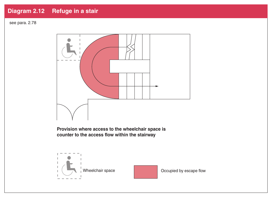
Diagram 2.13 Refuge formed by compartmentation
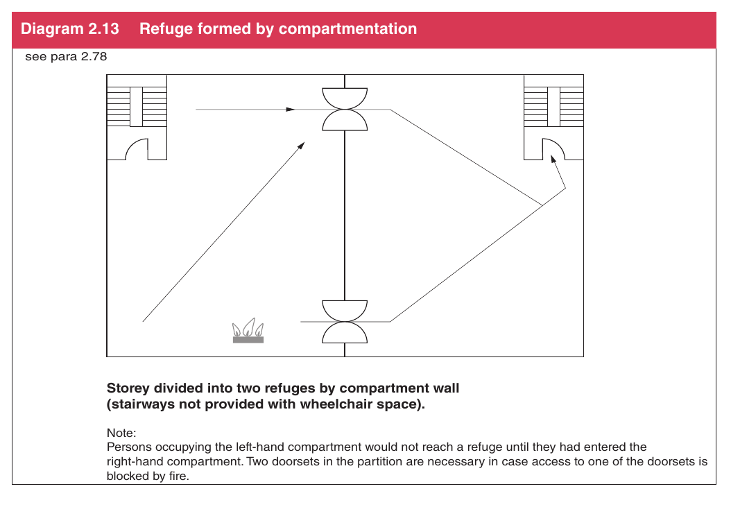
Page 74
#Source page 74
2.78The following are examples of satisfactory refuges –
(a)an enclosure such as a protected stairway (see diagram 2.12) or protected lobby, protected corridor or compartment (see diagram 2.13); and
(b)an area in the open air such as a flat roof, balcony, podium or similar place which is sufficiently protected (or remote) from any fire risk and provided with its own means of escape.
Where a refuge is within a pressurised stair the smoke control system should be in accordance with BS EN 12101-6.
2.79Each refuge should provide an area accessible to a wheelchair of at least 900 mm x 1400 mm in which a wheelchair user can await assistance. Where a refuge is in a protected stairway or protected lobby or protected corridor the wheelchair space should not reduce the width of the escape route. Where the wheelchair space is within a protected stairway, access to the wheelchair space should not obstruct the flow of persons escaping.
2.80Refuges and evacuation lifts should be clearly identified by appropriate signs. Where a refuge is in a lobby or stairway the sign should be accompanied by a blue mandatory sign worded “Refuge - keep clear”.
2.81To facilitate the effective evacuation of people temporarily waiting in each refuge an emergency voice communication system should be provided. It is essential that the occupants of each refuge are able to alert other people that they are in need of assistance and for them to be reassured that their presence in the refuge is known and that assistance will be forthcoming.
The emergency voice communication system should either -
a)comply with BS 5939-9 and consist of a Type B outstation at each refuge which communicates with a master station located in the building control room (where provided) or adjacent to the fire alarm panel; or
b)in some buildings, it may be more appropriate to use an alternative approach such as the use of wireless technology. Such technology needs to be readily operated by, and comprehensible to disabled people.
Evacuation lifts
2.82In general, it is not appropriate to use a lift when there is a fire in the building. However, in some circumstances a suitably sited and protected lift containing certain safety features may be used for evacuating people. Guidance on the design, location and use of an evacuation lift is given in the relevant recommendations of BS 9999 BS 5588-8. The evacuation lift installation should conform with BS EN 81-1 or BS EN 81-2 BS EN 81-20 and BS EN 81-70. as appropriate for the particular type of lift.
2.83For general provisions relating to the fire protection of lift installations, see paragraphs 2.99 and 2.100.
General provisions
#Source page 75
2.84The provisions in paragraphs 2.85 to 2.103 relate to the construction and protection of escape routes, some service installations and other matters associated with the design of escape routes.
Fire resistance
2.85Details of fire resistance test criteria and standards of performance are given in Section 4.
All walls, partitions and other enclosures (including roofs that form part of an escape route) required to have fire resistance to meet the provisions of this Section should have the appropriate performance given in Tables 4.1 and
4.2.Where glazed elements in such enclosures are only able to satisfy the relevant performance in respect of integrity (i.e. uninsulated glazing), their use should be limited in accordance with Table 2.8.
All doors required to have fire resistance to meet the provisions of this Section should have the appropriate performance given in Table 4.5, should be self-closing and the extent of any uninsulated glazing should be in accordance with Table 2.8.
Seating and gangways
2.86Permanent or retractable seating for closely seated audiences or spectators should be designed in accordance with the relevant recommendations of BS 9999 Clauses 8.1 to 8.4 of BS 5588-6.
Doors on escape routes
2.87In general doors on escape routes, whether fire doors or not, should only be fitted with locks or fastenings which are readily operated from the side approached by a person making an escape. The operation of such a lock or fastening should not involve the use of a key or the manipulation of more than one mechanism.
However, a door to a room may be locked when the room is not occupied provided that –
(a)it is not an access room to an inner room; or
(b)it is not part of an escape route for people in other parts of the building.
Where a door on an escape route has to be secured against entry when the building or part of the building is occupied, it should only be fitted with a lock or fastening which is readily operated, without a key, from the side approached by people making their escape. Similarly, where a secure door is operated by a code, combination, swipe or proximity card, biometric data or similar means, it should also be capable of being overriden from the side approached by people making their escape. Electrically powered locks should return to the unlocked position –
(i)on operation of the fire alarm system;
(ii)on loss of power or system failure; and
Page 76
#Source page 76
(iii) on activation of a manual door release unit (Type A) to BS EN 54-11 positioned at the door on the side approached by people making their escape. Where the door provides escape in either direction, a unit should be installed on both sides of the door.
2.88In the case of places of assembly, shop and commercial buildings, doors on escape routes from rooms with an occupant capacity of more than 60 should either not be fitted with lock, latch or bolt fastenings, or be fitted with panic fastenings in accordance with BS EN 1125.
Direction of opening of doors
2.89Doors on escape routes should, as far as practicable, open in the direction of escape. Doors should always open in the direction of escape in the following situations –
(a)from a place of special fire hazard;
(b)in the case of a building of Purpose Group 6 or 7 – where the number of occupants is more than 10; and
(c)in the case of a building of any other purpose group – where the number of people likely to use the door in the event of a fire is more than 60.
Doors on escape routes should open through not less than 90° and swing clear of any change in floor level, other than a threshold or single step (with a rise of not more than 170 mm) on the line of the doorway. At no point of its swing should a door reduce the effective width of any escape route across a landing.
A door that opens towards a corridor should be recessed to prevent its swing from encroaching on the effective width of the corridor.
2.90Revolving doors, automatic doors and turnstiles should not be permitted across escape routes unless –
(a)they have non-automatic swing doors of the required width immediately adjacent;
(b)they are of the required width and easily openable in an emergency; or
(c)where the doors are automatic –
(i)they are of the required width and fail safe to the open position; or
(ii)they are of the required width and are provided with a monitored failsafe system for opening the doors if the main electricity supply fails.
Page 77
#Source page 77
Vision panels in doors
2.91A glazed vision panel, or panels of not less than 0.1 m2, should be provided in a door that subdivides a corridor, or where a door swings both ways.
The vision panel or panels should include –
(a)a lower zone of visibility not more than 500 mm to not less than 800 mm; and
(b)an upper zone of visibility not more than 1150 mm to not less than 1500 mm,
measured from the floor and located towards the leading edge of the door. See Diagram 2.14.
Height and width of escape routes
2.92All escape routes should have a clear headroom of not less than 2 m and there should be no projections below this height, except for door frames.
The width of an escape route should be measured at 1.5 m above floor level or pitch line. The projection of handrails, if less than 100 mm, and stringers, skirtings and architraves if less than 30 mm, on either or both sides should be ignored.
The width of an escape doorway from a room should be taken as the clear width when the door is open (see Diagram B.6).
Diagram 2.14 Vision panels in doors
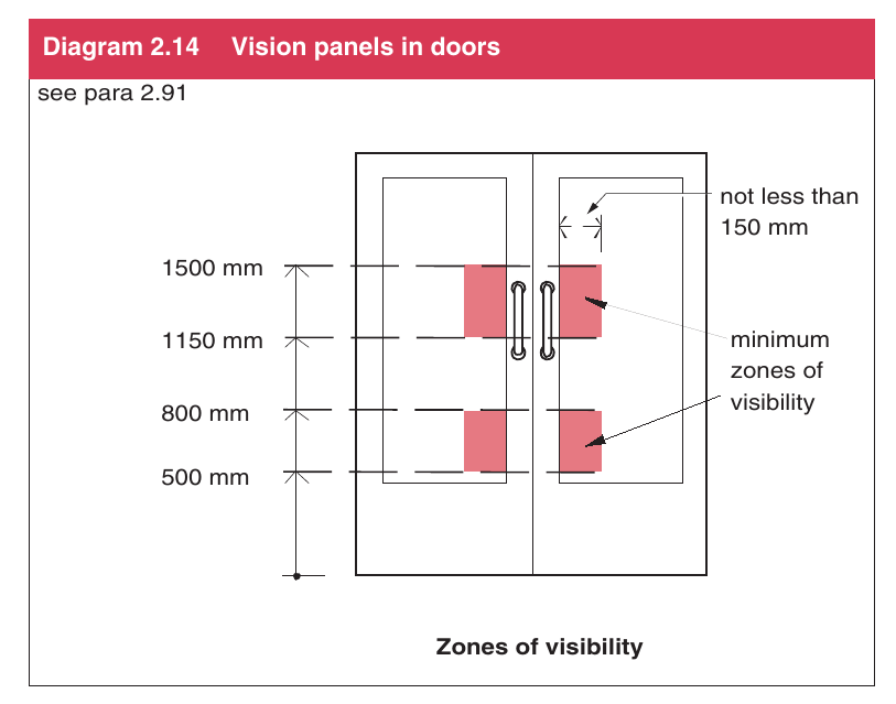
Page 78
#Source page 78
Construction of escape stairs
2.93Other than in a dwellinghouse every escape stair and its associated landings should be constructed of materials of limited combustibility where –
(a)it is the only stair serving the building (or part of the building), unless the building is of two or three storeys and is of Purpose Group 1(a) or Purpose Group 3;
(b)it is within a basement storey, unless it is within a flat with more than one storey;
(c)the height to any storey which it serves is more than 18 m above ground or final exit level;
(d)it is a firefighting stairway (see Section 6); or
(e)it is external, except in the case of a stair that connects the final exit level with a floor or flat roof less than 6 m above or below final exit level.
Combustible materials may be added to the upper surface of these stairs except in the case of firefighting stairways.
Helical stairs and spiral stairs
2.94Helical stairs or spiral stairs may form part of an escape route (other than for the evacuation of disabled people or for the evacuation of pupils in schools) provided that they are designed in accordance with BS 5395: Part 2. Helical stairs and spiral stairs should be of Type E (public stair) where they are intended to be used by the public.
Final exits
2.95A final exit should –
(a)have a width not less than the width of the escape route it serves, the width of a final exit doorway should be measured in accordance with B.1(g) of Appendix B;
(b)be sited to ensure rapid dispersal to a place of safety;
(c)be readily apparent to people who need to use it; and
(d)be sited clear of any fire hazards including fire or smoke issuing from a basement, and from openings to transformer rooms, solid waste stores, boiler rooms and similar hazards.
Page 79
#Source page 79
Lighting of escape routes
2.96Other than in a dwellinghouse all escape routes should have adequate artificial lighting.
The areas listed in Table 2.9 should also have escape lighting, which will illuminate the escape route if the mains supply fails. Standards for the installation of escape lighting are given in BS 5266-1.
Escape lighting to escape stairways should be on a separate circuit to that supplying any other part of the escape route or building.
| Table 2.9 Provisions for escape lighting | |
|---|---|
| Purpose group of the building or part of the building | Areas requiring escape lighting |
| Purpose Group 2 | All common escape routes(1) |
| Purpose Groups 3, 4(2), 6 and 7(a) | (a) Underground or windowless accommodation (b) Stairways in a central core or serving storey(s) more than 18 m above ground level (c) Internal corridors more than 30 m long (d) Open-plan areas more than 60 m² |
| Purpose Groups 4(3) and 7(b) | All escape routes(1) (except in a shop of not more than three storeys, with no sales floor greater than 280 m², provided that the shop is not a restaurant or bar) |
| Purpose Group 5 | All escape routes (1) and accommodation except for– (a) accommodation open on one side to view sport or entertainment during daylight hours; and (b) parts of school buildings with natural light and used only during normal school hours |
| All purpose groups | (a) All toilet accommodation having a floor area more than 8 m² (b) Windowless toilet accommodation having a floor area not more than 8 m² (c) Electricity generator rooms (d) Switch room/battery room for emergency lighting system (e) Emergency control room |
| Notes: (1) Including external escape routes. (2) Those areas of the building to which the public are not admitted. (3) Those areas of the building to which the public are admitted. |
Page 80
#Source page 80
Protected power circuits
2.97Where it is critical for electrical circuits to be able to continue to function during a fire, protected circuits are needed. The potential for damage to cables forming protected circuits should be limited by the use of sufficiently robust cables, careful selection of cable routes and/or by the provision of physical protection in areas where cables may be susceptable to damage. Methods of cable support should generally be non-combustible and such that circuit integrity will not be reduced below that afforded by the cable.
A protected circuit for operation of equipment in the event of a fire should consist of cables meeting at least the requirements for PH 30 classification when tested in accordance with BS EN 50200 (incorporating Appendix E), or equivalent standard. It should follow a route selected to pass only through parts of the building in which the fire risk is negligible and should be separate from any circuit provided for another purpose.
In large or complex buildings there may be fire protection systems that need to operate for an extended period during a fire. Further guidance on the selection of cables for such systems is given in BS 5839-1, BS 5266-1 and BS 7346-6.
Exit signs
2.98Other than in a dwellinghouse, exits on escape routes except those in normal use for egress, should be marked with signs which are readily visible so that the occupants of a building can clearly and readily see where the exits are.
The signs should comply with the relevant requirements of BS 5499-1 and BS 5499-4. (Advice on fire safety signs, including emergency escape signs, is given in HSE publication: Safety signs and signals: guidance on regulations.)
Page 81
#Source page 81
Fire protection of lift installations
2.99As lifts penetrate floors and are usually sited within or adjacent to circulation routes they may prejudice the means of escape from the building. To safeguard against this a lift and its associated machine room should comply with the following provisions.
A lift should be –
(a)in a protected shaft where it penetrates a compartment floor (see paragraph 4.25);
(b)within the enclosure of a protected stairway where permitted by paragraph 2.72; or
(c)enclosed with fire-resisting construction where its siting prejudices the means of escape.
A lift should not be continued down to serve a basement storey in a building (or part of a building) the upper storeys of which are served by a single escape stairway or if the lift is within the enclosure to an escape stairway which is terminated at ground level.
A lift in a basement or enclosed car park should be approached through a protected lobby or protected corridor unless it is in a protected stairway enclosure.
A lift should be approached through a protected lobby or protected corridor on a storey which contains a high fire risk area, if the lift also delivers directly into a corridor serving sleeping accommodation.
Lift machine rooms should be sited over the lift shaft where practicable. Where the lift is within a protected stairway which is the only protected stairway in a building (or part of a building) the machine room should be located outside the protected stairway, if it cannot be sited over the lift shaft.
In a building designed for phased evacuation, where the lift is not within a protected stairway, the lift entrance should be separated from the floor area on every storey by a protected lobby [see paragraph 2.66(b)].
2.100A feature lift such as a wall-climber lift which rises within a large volume such as a mall or atrium and is not in a conventional well, may be at risk if it runs through a smoke reservoir. In which case care is needed to maintain the integrity of the smoke reservoir and to protect the occupants of the lift.
Mechanical ventilation systems
2.101A mechanical ventilation system should be designed so that in a fire either –
(a)the air movement in the building is directed away from escape routes; or
(b)the system is closed down.
Where the system re-circulates air it should comply with the relevant recommendations of BS 9999 provisions of BS 5588-9 in respect of its operation under fire conditions.
Page 82
#Source page 82
Where a pressurization system is installed in a protected stairway all mechanical ventilation and air conditioning systems in the building should be compatible with it when operating under fire conditions.
Waste chutes and storage
2.102A room used for the storage of waste or containing a waste chute should be –
(a)separated from other parts of the building by fire-resisting construction;
(b)located outside protected stairways and protected lobbies; and
(c)accessed from the open air or from a protected lobby which has not less than 0.2 m2 of permanent ventilation.
Shop store rooms
2.103Where the siting of a fully enclosed walk-in store room within a shop prejudices a means of escape it should be separated from the retail areas by fire-resisting construction other than where –
(a)it is provided with an automatic fire detection and fire alarm system to BS 5839-1 of at least Category L5 standard with a smoke detector or detectors located in the store room; or
(b)it is fitted with an automatic sprinkler system in accordance with Section 8 complying with the relevant recommendations of BS 5306-2 or BS EN 12845.
See Table 4.1, Item 14 (c).
Page 83
#Source page 83
Section 3 Internal fire spread - Linings
3.1This Section contains provisions to restrict the spread of flame over the internal wall and ceiling linings and, in some locations, to limit the contribution they will make to the growth of the fire. This Section should be read in conjunction with paragraphs 1.7 to 1.11.
The choice of materials for wall and ceiling linings can significantly affect the spread of a fire and its rate of growth, even though such linings are not likely to be the materials first ignited. This choice is particularly important in circulation spaces where linings may offer the main means by which fire spreads, and where rapid spread is most likely to prevent occupants from escaping.
Several properties of lining materials influence fire spread. These include the ease of ignition and the rate at which the lining material gives off heat when burning. The guidance relating to the European fire tests and classification provides for control of internal fire spread through control of these properties. This booklet does not give detailed guidance on other properties such as the generation of smoke and fumes.
3.2Provisions regarding linings within concealed spaces, above fire-protecting suspended ceilings and enclosures to sanitary pipework are contained in Section 4. Additional provisions regarding the internal surface of rooflights are contained in Section 5.
3.3This Section does not contain provisions regarding the upper surface of floors and stairs because they are not significantly involved in a fire until it is well developed. Consequently, they are not likely to contribute to the early stages of fire spread that have most impact on the safety of occupants.
Furniture and fittings can have a major effect on fire spread but it is not possible to control them under the Building Regulations. Consequently, they are not covered by this booklet.
Classification of performance of materials or products (National classification)
3.4The surface spread of flame classification of a lining should be ascertained by testing in accordance with BS 476: Part 7. The classifications given in such tests are Classes 1, 2, 3 and 4. Class 0 is achieved where a lining material or the surface of a composite product is either –
(a)composed throughout of materials of limited combustibility; or
(b)a Class 1 material which has when tested to BS 476: Part 6, a fire propagation index (I) of not more than 12 and a sub-index (i1) of not more than 6.
A composite material of limited combustibility which does not have a surface complying with (a) or (b) should be classified by test.
Class 0 is the highest classification and Class 4 materials are not acceptable.
Page 84
#Source page 84
3.5The term thermoplastic material includes all synthetic polymeric materials which have a softening point lower than 200ºC when tested to BS EN ISO 306: Method A120 Plastics. For the purposes of this Section (and Section 4) thermoplastic materials are classified as TP(a) rigid and TP(a) flexible and TP(b) as follows –
(a)To be classified as TP(a) rigid, a thermoplastic material should be –
(i)rigid solid PVC sheet;
(ii)solid polycarbonate sheet not less than 3 mm thick;
(iii)double or multiple skin rigid sheet of unplasticised PVC or polycarbonate which achieves a classification of Class 1; or
(iv)a rigid product, a specimen of which (at the thickness of the product as put on the market) when tested to BS 2782-0: Method 508A, extinguishes before the flame reaches the first mark and after removal of the burner, the flaming or afterglow does not exceed 5 seconds.
(b)To be classified as TP(a) flexible, a thermoplastic material should be a flexible product not greater than 1 mm thick which complies with the Type C requirements of BS 5867: Part 2 when tested to BS 5438 Test 2 (excluding the cleansing procedure) with the flame applied to the surface of the specimens for 5, 15, 20 and 30 seconds respectively.
(c)To be classified as TP(b) a thermoplastic material should be –
(i)rigid solid polycarbonate sheet less than 3 mm thick;
(ii)double or multiple skin polycarbonate sheet which does not achieve a classification of Class 1; or
(iii) a product which, when a specimen of material between 1.5 mm and 3 mm thick, tested to BS 2782-0: Method 508A, has a rate of burning not greater than 50 mm per minute.
Note – Currently, no new guidance is possible on the assessment or classification of thermoplastic materials under the European system since there is no generally accepted European test procedure and supporting comparative data.
3.6Where a thermoplastic material is used as a lining to protect a wall or ceiling but is not fully bonded to a non-thermoplastic substrate the surfaces of both the thermoplastic material and the substrate should meet the provisions of paragraph 3.10. However, where a thermoplastic material is fully bonded to a non-thermoplastic substrate only the surface of the composite need meet the provisions of paragraph 3.10.
Page 85
#Source page 85
Classification of performance of materials or products (European classification)
3.7Performance in terms of reaction to fire to be met by construction products is determined by Commission Decision 200/147/EC of 8th February 2000 implementing Council Directive 89/106/EEC as regards the classification of the reaction to fire performance of construction products.
The fire classification of a lining product should be in accordance with BS EN 13501-1 Fire classification of construction products and building elements, Part 1: Classification using test data from reaction to fire tests. The reaction to fire tests are –
(a)BS EN ISO 1182 Reaction to fire tests for building products – Non-combustibility test;
(b)BS EN ISO 1716 Reaction to fire tests for building products – Determination of the gross heat of combustion (calorific value);
(c)BS EN 13823 Reaction to fire tests for building products – Building products excluding floorings exposed to the thermal attack by a single burning item;
(d)BS EN ISO 11925-2 Reaction to fire tests – Ignitability of building products subjected to direct impingement of flame – Part 2: Single-flame source test; and
(e)BS EN 13238 Reaction to fire tests for building products – Conditioning procedures and general rules for selection of substrates.
The classifications given in BS EN ISO 13501-1 are A1, A2, B, C, D, E and
F. Class A1 is the highest classification and Class F is the lowest.
Classes A2, B, C and D obtain an additional classification of –
(i)s1, s2 or s3 regarding smoke production; and
(ii)d0, d1 or d2 regarding the production of flaming droplets and/or particles.
Where a classification includes ‘s3,d2’ this means that there is no limit set for smoke production and/or flaming droplets/particles.
3.8National classifications do not automatically equate with the equivalent European classifications therefore products cannot typically assume a European class unless they have been tested accordingly.
Definition of wall and ceiling
3.9For the purposes of the performance of wall and ceiling linings –
(a)a wall should include –
(i)the surface of glazing (except glazing in a door); and
(ii)any part of a ceiling which slopes at an angle of more than 70º to the horizontal;
Page 86
#Source page 86
(b)a wall should not include –
(i)doors and door frames;
(ii)window frames and frames in which glazing is fitted;
(iii)architraves, cover moulds, picture rails, skirtings and similar narrow members; and
(iv)fire surrounds, mantleshelves and fitted furniture;
(c)a ceiling should include –
(i)the surface of glazing; and
(ii)any part of a wall which slopes at an angle of 70º or less to the horizontal; and
(d)a ceiling should not include –
(i)trap doors and their frames;
(ii)the frames of windows or rooflights and frames in which glazing is fitted; and
(iii) architraves, cover moulds, picture rails, exposed beams and similar narrow members.
Performance of wall and ceiling linings
3.10The surface lining of a wall and of a ceiling should have a classification not lower than the relevant Class given in Table 3.1, subject to the provisions of paragraphs 3.11 to 3.16.
3.11In a room any part of the surface of a wall may be of a Class lower than that given in Table 3.1 [but not lower than Class 3 (National class) or Class D-s3,d2 (European class)] if the total area of those parts in any one room does not exceed either –
(a)half the floor area of the room; or
(b)(i) in the case of a building of Purpose Group 1 or 2 – 20 m2; or
(ii) in the case of a building of any other purpose group – 60 m2, whichever is the lesser.
3.12A suspended ceiling which is to contribute to the fire resistance of a floor/ceiling assembly having a fire resistance of more than 60 minutes should, in addition to having the classification given in Table 3.1, be constructed of materials of limited combustibility (see Table 4.3).
3.13The ceiling of a room may be constructed, either as a suspended or stretched skin membrane, from panels of a thermoplastic material of the TP(a) flexible classification provided that –
(a)each panel is supported on all its sides;
(b)each panel is not more than 5 m2 in area; and
(c)it is not a fire-resisting ceiling.
Page 87
#Source page 87
Table 3.1 Surface classifications for walls and ceilings
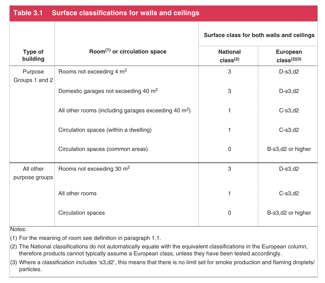
Rooflights
3.14Other than in a protected stairway a rooflight may be of a classification lower than the relevant Class given in Table 3.1 provided that –
(a) where it is –
(i)a plastic material which has a lower surface with a classification not lower than Class 3; or
(ii)a thermoplastic material which has a lower surface with a classification not lower than Class 3 or is classified as a TP(a) rigid or TP(b) product,
the size of the rooflight does not exceed the relevant maximum area given in Table 3.2; and
(b) where there is more than one rooflight in the ceiling of a room or space –
(i)the area of rooflights does not exceed the relevant maximum total area given in Table 3.2; and
Page 88
#Source page 88
(ii)the disposition of the rooflights complies with the limitations given in Diagram 3.1.
The upper surface of a rooflight is subject to the provisions of Section 5.
Windows and internal glazing
3.15A window in the external wall of a circulation space and all internal glazed areas should be glazed with a material having a classification not lower than that given in Table 3.1.
A window in an external wall of a room may be glazed with a thermoplastic material classified as a TP(a) rigid product.
Lighting diffusers
3.16This paragraph applies to a lighting diffuser which forms part of a ceiling. It does not apply to the diffuser of a light fitting which is attached to the soffit of, or suspended beneath, a ceiling.
Table 3.2 Limitations on Class 3 plastic rooflights and thermoplastic rooflights and lighting diffusers in suspended ceilings
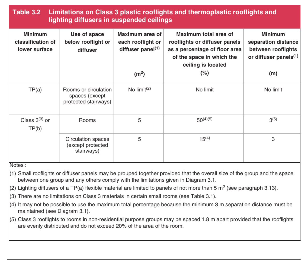
Page 89
#Source page 89
Lighting diffusers may be translucent or open-structured elements and may be part of a light fitting or be used below a rooflight or other source of light.
A thermoplastic lighting diffuser should not be incorporated in a fire-protecting or fire-resisting ceiling unless it has been satisfactorily tested as part of a luminaire within a ceiling assembly that provides the appropriate fire resistance. A ceiling in a room or in a circulation space (other than a protected stairway) may incorporate a thermoplastic lighting diffuser provided that –
(a)the wall and ceiling surfaces exposed within the space above the ceiling (other than the upper surface of the lighting diffuser) comply with the classification given in Table 3.1 for the space below the ceiling; and
(b)the lighting diffuser is either –
(i)classified as a TP(a) rigid product; or
(ii)classified as a TP(b) product and is loosely mounted so that it will fall out of its mounting on initial heating. Where more than one such lighting diffuser is fitted, they should be limited in their extent in accordance with Table 3.2. Small lighting diffusers may be grouped together (see Note (1) to Table 3.2 and Diagram 3.1).
Diagram 3.1 Limitations on groups of Class 3 plastic rooflights and TP(b) t rooflights and lighting diffusers in suspended ceilingshermoplastic
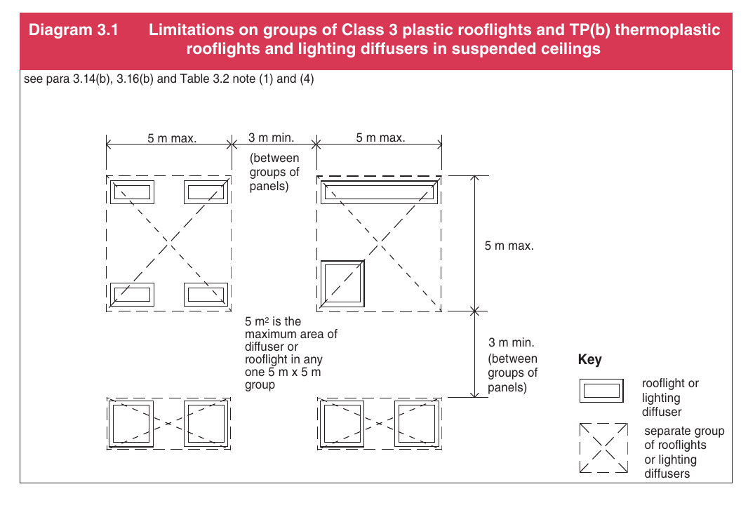
Page 90
#Source page 90
Section 4 Internal fire spread - Structure
4.1The spread of fire within a building can be restricted by –
(a)ensuring the elements of structure and certain other components of the building have a minimum standard of fire resistance;
(b)subdividing the building into compartments with fire-resisting construction;
(c)subdividing concealed and extensive cavities within the construction; and
(d)protecting openings in, and penetrations through, fire-resisting construction.
Where a building is divided into separated parts by a compartment wall (or walls), running the full height of the building in a continuous vertical plane, the provisions of this Section may be applied separately to each separated part.
Tests for fire resistance
4.2The fire resistance of an element of structure or other component of a building is a measure of its ability to withstand the effects of fire in one or more of the following ways –
(a)resistance to collapse (loadbearing capacity) denoted ‘R’ in European classification;
(b)resistance to fire penetration (integrity) denoted ‘E’ in European classification; and
(c)resistance to transfer of excessive heat (insulation) denoted ‘I’ in European classification.
National tests
4.3Under National determination performance in respect of fire resistance should be determined in accordance with, in the case of –
(a)loadbearing elements – BS 476: Parts 20 and 21;
(b)non-loadbearing elements – BS 476: Parts 20 and 22;
(c)suspended ceilings – BS 476: Parts 20 and 23;
(d)ventilation ducts – BS 476: Parts 20 and 24; and
(e)any element of construction tested prior to 1st January 1988 – BS 476: Part 8.
Page 91
#Source page 91
European tests
4.4Under European determination performance in respect of fire resistance should be classified in accordance with Commission Decision 2000/367/EC of 3rd May 2000 implementing Council Directive 89/106/EEC as regards the classification of the resistance to fire performance of construction products, construction works and parts thereof. The fire resistance tests are –
(a)BS EN 1363-1 Fire Resistance tests – Part 1: General requirements;
(b)BS EN 1363-2 Fire Resistance tests – Part 2: Alternative and additional procedures;
(c)BS EN 1364-1 Fire Resistance tests for non-loadbearing elements – Part 1: Walls;
(d)BS EN 1364-2 Fire Resistance tests for non-loadbearing elements – Part 2: Ceilings;
(e)BS EN 1365-1 Fire Resistance tests for loadbearing elements – Part 1: Walls;
(f)BS EN 1365-2 Fire Resistance tests for loadbearing elements – Part 2: Floors and roofs;
(g)BS EN 1365-3 Fire Resistance tests for loadbearing elements – Part 3: Beams;
(h)BS EN 1365-4 Fire Resistance tests for loadbearing elements – Part 4: Columns;
(i)BS EN 1366-1 Fire Resistance tests for service installations – Part 1: Ventilation ducts Ducts;
(j)BS EN 1366-2 Fire Resistance tests for service installations – Part 2: Fire dampers;
(k)BS EN 1634-1 Fire resistance and smoke control tests for door, shutter and openable window assemblies and elements of building hardware – Part 1: Fire resistance tests for doors, shutters and openable windows;
(l)BS EN 1634-2 Fire resistance and smoke control tests for door, shutter and openable window assemblies and elements of building hardware – Fire resistance characterisation test for elements of building hardware;
(m)BS EN 1634-3 Fire Resistance tests for door and shutter assemblies – Part 3: Smoke control doors and shutters; and
(n)BS EN 81-58 Safety rules for the construction and installation of lifts – Examination and tests – Part 58: Landing doors fire resistance test.
See Appendix C for full details of all publications referred to.
Specific provisions of test
4.5Provision for an element of structure or other component of the building to have a specific period of fire resistance means that it should have not less than that period, in respect of the relevant aspects of performance given in Table 4.1.
Page 92
#Source page 92
Table 4.1 Specific provisions of test for fire resistance of elem components of a buildingents of structure and other
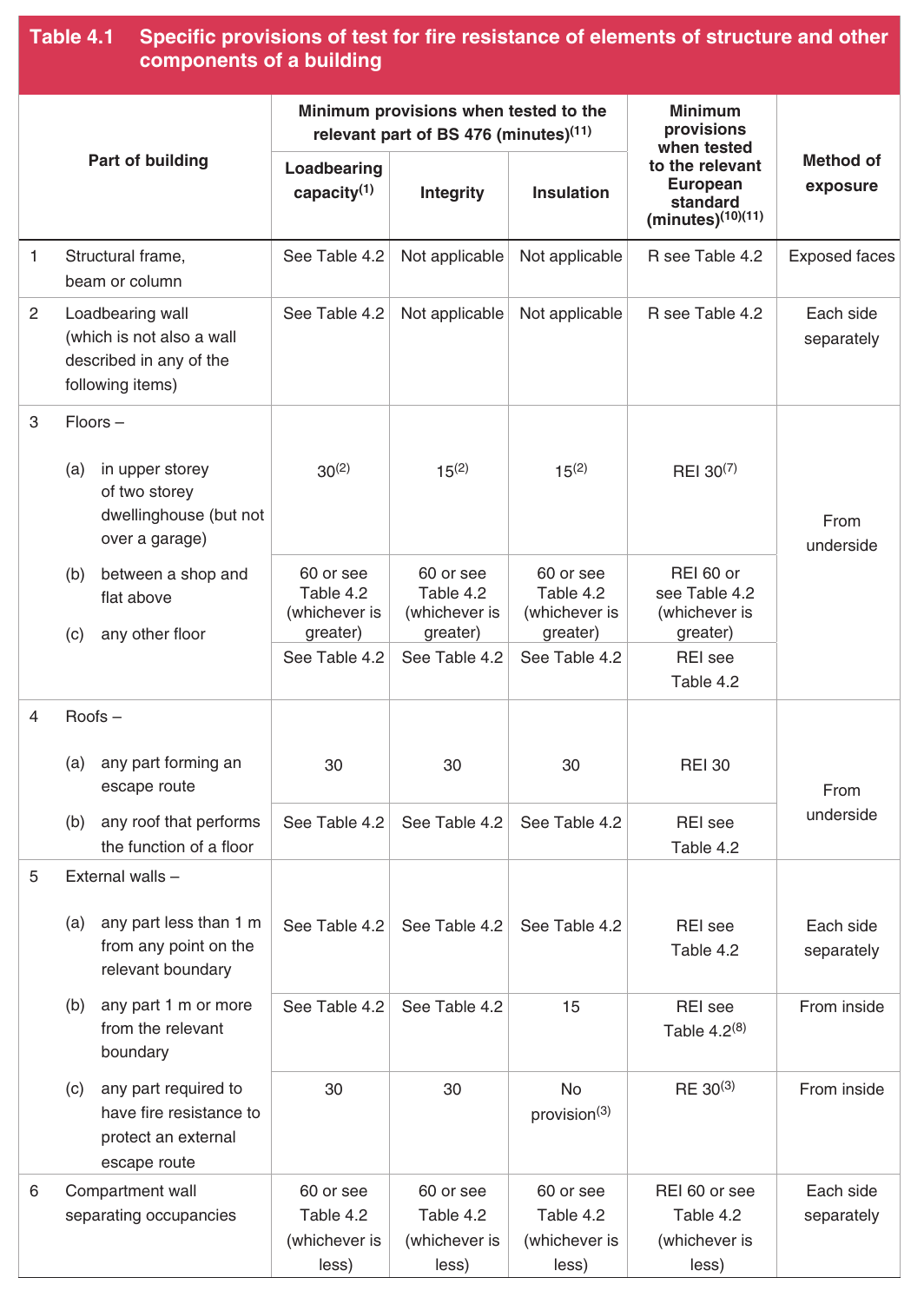
Page 93
#Source page 93
Table 4.1 Specific provisions of test for fire resistance of eleme components of a building (cont’d)nts of structureand other
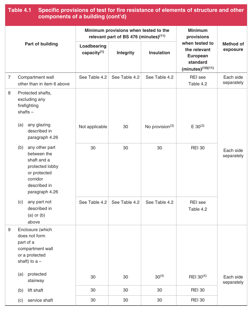
Page 94
#Source page 94
Table 4.1 Specific provisions of test for fire resistance of ele components of a building (cont’d)ments of structure and other
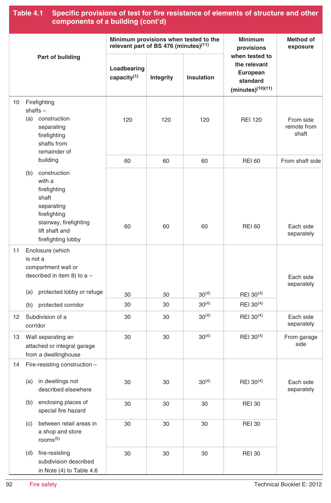
Page 95
#Source page 95
Table 4.1 Specific provisions of test for fire resistance of elements of structure and other components of a building (cont’d)
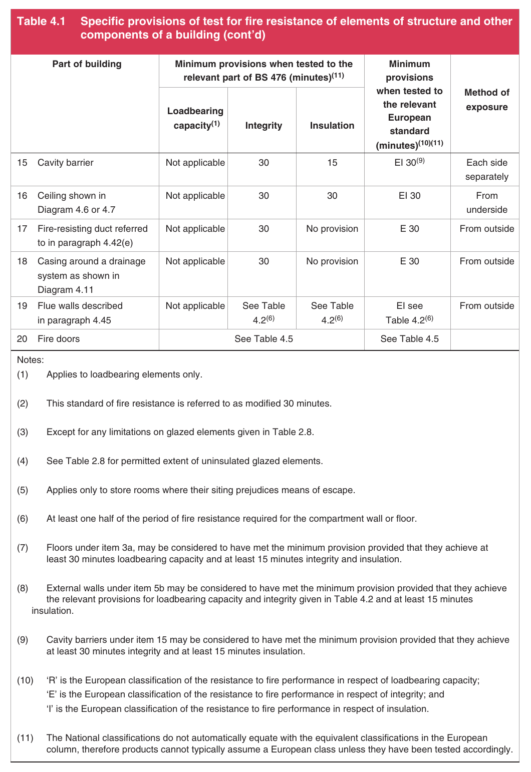
Page 96
#Source page 96
Fire resistance of elements of structure and certain other components of the building
4.6An element of structure and those other components of the building given in Table 4.1 should have a minimum period of fire resistance of not less than that given in Tables 4.1 and 4.2 for the purpose group of the building.
Where one element of structure or other component supports, carries or gives stability to another, the fire resistance of the supporting element or component should be not less than the minimum period of fire resistance for the other element (whether that other element is loadbearing or not).
Where an element or structure or other component forms part of more than one building or compartment, the fire resistance of that element or component should be not less than the greater of the relevant provisions.
Fire protecting suspended ceilings
4.7A suspended ceiling will only be accepted as contributing to the fire resistance of a floor where that ceiling is of the appropriate type given in Table 4.3.
Fire-resisting construction
4.8Where an element of structure or other component of the building is required to have fire resistance it may be constructed in accordance with an appropriate specification in Part II of the Building Research Establishment Report – Guidelines for the construction of fire-resisting structural elements (BR 128: 1988).
Places of special fire hazard
4.9Every place of special fire hazard should be enclosed by fire-resisting construction [see Table 4.1, item 14(b)].
Page 97
#Source page 97
Table 4.2 Minimum periods offire resistance
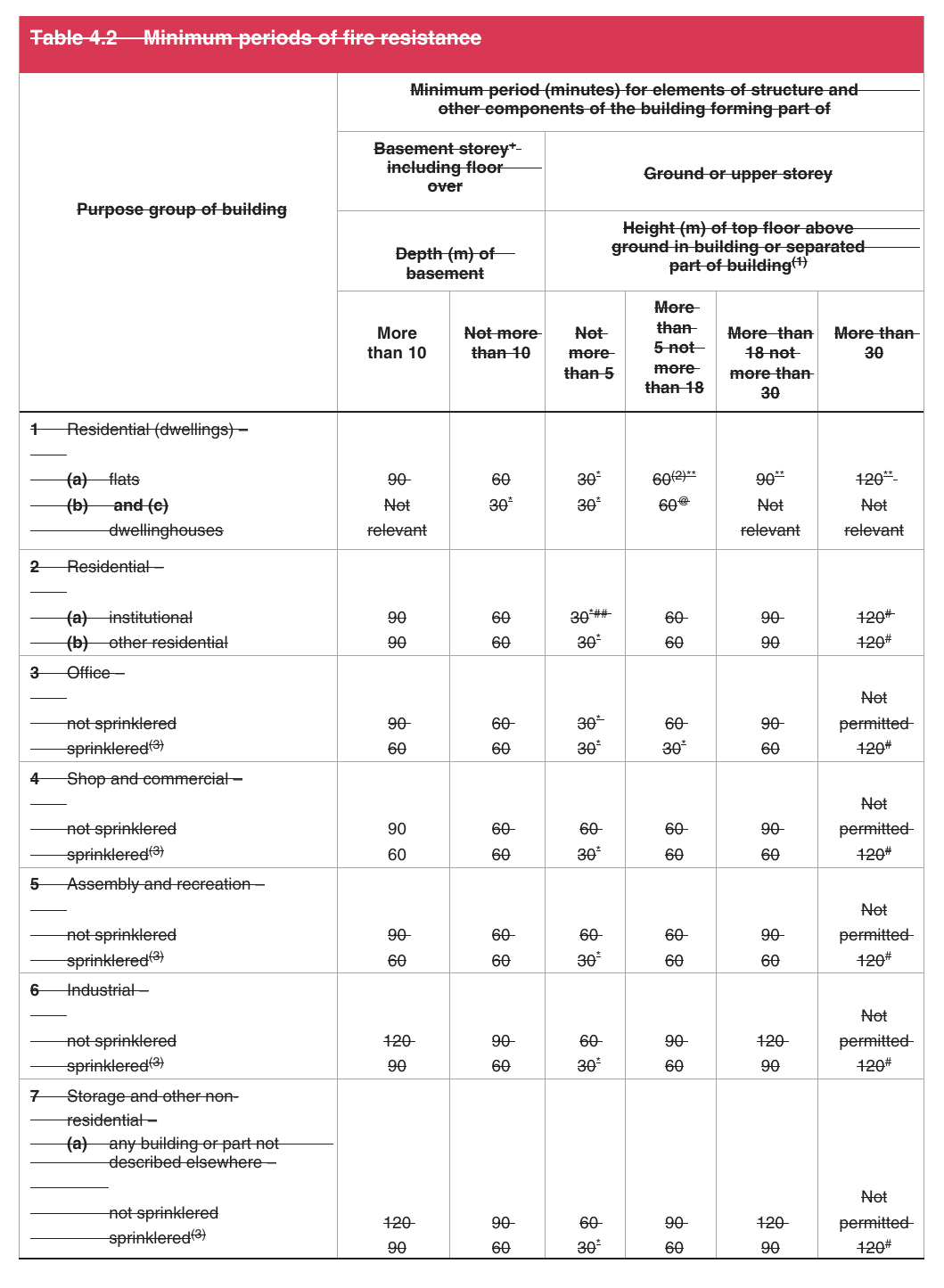
Page 98
#Source page 98
Table 4.2 Minimum periods of fire resistance (cont’d)
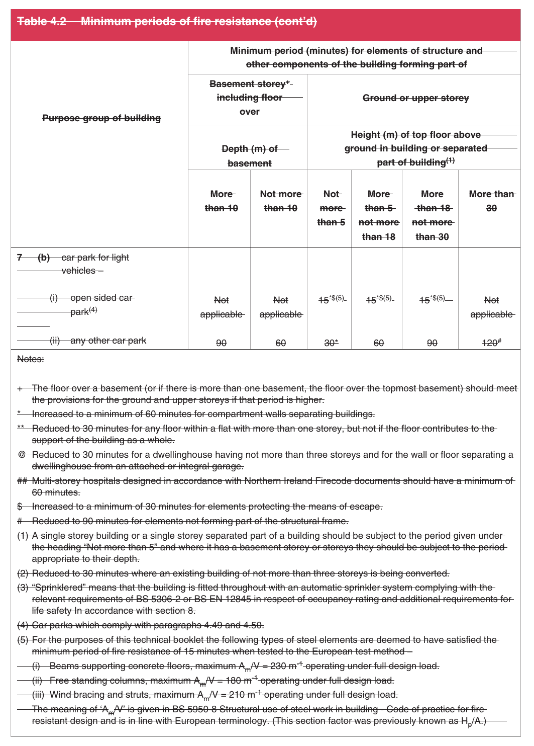
Page 99
#Source page 99
Table 4.2 NEW Minimumperiods of fire resistance
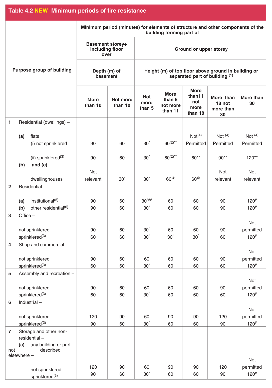
Page 100
#Source page 100
Table 4.2 New Minimum periods of fire resistance (cont’d)
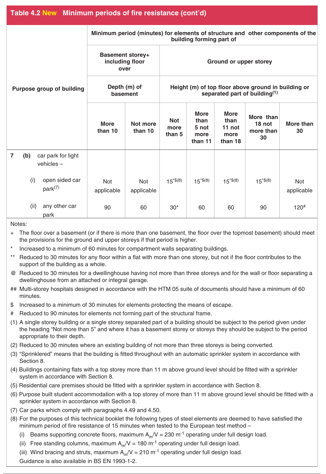
Page 101
#Source page 101
Table 4.3 Limitations of fire-protecting suspended ceilings
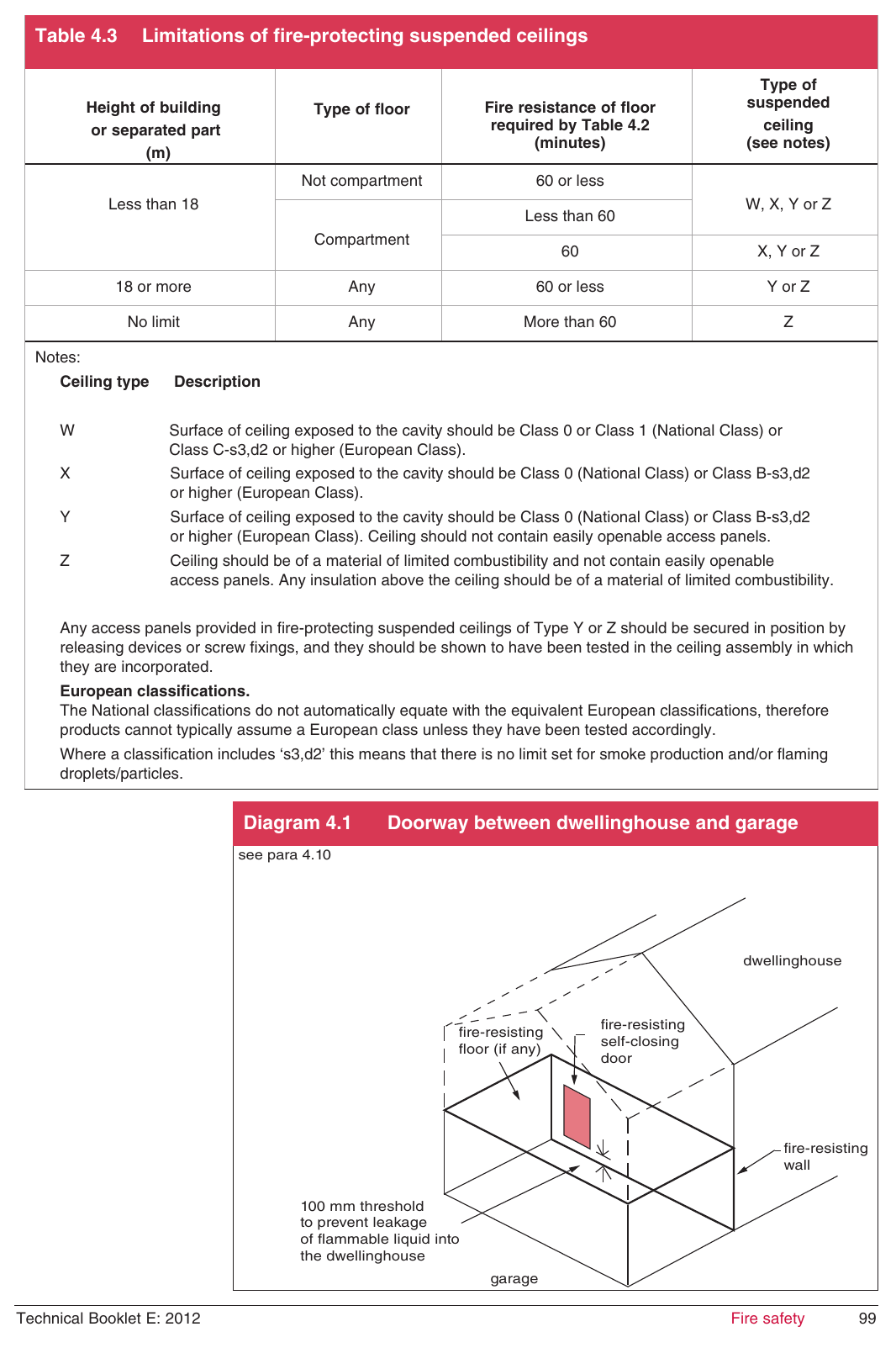
Page 102
#Source page 102
Dwellinghouses with attached garages
4.10Where a dwellinghouse has an attached or integral garage it should be separated from the garage by fire-resisting construction with no openings other than for a fire-resisting self-closing door. In the case of a doorway between the dwellinghouse and the garage the doorway should have a threshold height of not less than 100 mm above the garage floor level to prevent the leakage of flammable liquid into the dwellinghouse (see Diagram 4.1).
Variations of the provisions regarding fire resistance
4.11A provision for an element of structure to have fire resistance should not apply to –
(a)any part of the structure which only supports a roof unless –
(i)the roof performs the function of a floor, e.g. as a means of escape, for parking of vehicles, etc.;
(ii)the structure is part of, or is essential for the stability of an external wall which, under the provisions of Section 4, cannot be an unprotected area; or
(iii)the structure is part of or supports a compartment wall or a wall between a dwellinghouse and an attached or integral garage;
(b)in the case of a single storey building or a building which consists of a ground storey and one or more basement storeys – any element of structure which forms part of the ground storey unless the element –
(i)supports a gallery; or
(ii)is located as defined in sub-paragraph 4.11 (a)(ii) or 4.11 (a)(iii);
(c)the lowest floor of a building; and
(d)a platform floor.
4.12Where one side of a basement storey or compartment is (due to the slope of the ground) open at and provides – means of escape and fire and rescue access at ground level and smoke venting, the period of resistance for the elements of structure and other components of the building in that basement storey or compartment should be that appropriate to a storey above the ground.
4.13Where the roof space of an existing two storey dwellinghouse is to be converted to form a new storey the provisions of this Section are for the floors, both old and new, to have full 30 minutes fire resistance. However, the existing first floor construction need not be upgraded where it separates only rooms (and not circulation spaces) provided that –
(a)only one storey is being added;
(b)the new storey contains not more than two habitable rooms;
(c)the total area of the new storey is not more than 50 m2;
(d)it has at least modified 30 minutes fire resistance; and
(e)the provisions of paragraphs 2.17 to 2.22 are met.
Page 103
#Source page 103
Raised storage floors
4.14Raised free-standing floors supported by racking are frequently erected for storage purposes and whether they are considered as a gallery or as a floor forming a storey the provisions for fire resistance for elements of structure apply.
In the case of automated storage systems where people do not normally frequent any of the raised storage tiers it is not necessary to provide the storage structure with fire resistance.
Where people frequent the storage tiers in the course of their normal use, the provisions for fire resistance for the raised storage floor and its supporting structure may be dispensed with where the number of persons likely to be on the raised floor at any one time is low (and does not include members of the public) and the raised floor –
(a)is within a single storey building or compartment and is structurally free-standing;
(b)consists of only one tier with the space both above and below used only for storage purposes;
(c)is not more than 20 m in both width and length and does not exceed one half of the floor area of the space in which it is situated. However, these limits should not apply where the building is fitted throughout with an automatic sprinkler system in accordance with Section 8 complying with the relevant recommendations of BS 5306-2 or BS EN 12845 in respect of occupancy rating and additional requirements for life safety;
(d)is served by a stair or stairs to comply with the relevant maximum travel distance given in Table 2.3 and at least one stair discharges within 4.5 m of an exit from the building or compartment;
(e)has a surface classification on the underside not lower than Class 3 (National class) or Class D-s3,d2 (European class) (see paragraphs
3.4and 3.7); and
(f)is designed and constructed so that any persons on the floor will be readily aware of a fire starting on the lower level. Design and construction features include the use of perforations in the floor, leaving a space between the floor and the walls of the space housing it and automatic fire detection and alarm systems. However, where either the length or width of a raised storage floor is greater than 10 m an automatic fire detection and fire alarm system to BS 5839-1 of at least Category L5 standard with a smoke detector or detectors located to give warning of a fire below the floor should be provided.
Page 104
#Source page 104
Compartmentation
4.15The degree to which a building or separated part of a building is subdivided into compartments is related to the use of and the fire load in the building, the height to the top storey and the provision or otherwise of a sprinkler system. Compartmentation may assist in meeting the provisions of Section 2 or Section 5 of this Technical Booklet.
For compartmentation to be effective there should be continuity at the junctions of the fire-resisting elements enclosing the compartment and any opening from one compartment to another should not present a weakness. The spaces which connect compartments, e.g. stairs, service shafts, etc., should be enclosed to form protected shafts and their walls and floors should be constructed as compartment walls and compartment floors.
4.16In the case of a two storey building of Purpose Group 4 or 6, where the use of the upper storey is ancillary to the main use of the ground storey, the ground storey may be treated as a single storey building for compartmentation purposes provided that –
(a) the floor area of the upper storey is not more than –
(i) one fifth of the floor area of the ground storey; or
(ii) 500 m2, whichever is the lesser; and
(b) the upper storey is a separate compartment.
Provision of compartment walls and compartment floors
4.17In buildings of all purpose groups –
(a)a compartment wall should be constructed where a wall –
(i)is common to two or more buildings; or
(ii)is provided to divide a building into separated parts; and
(b)a compartment wall or a compartment floor, as appropriate should be constructed to separate parts of a building which are in different purpose groups of Appendix A.
4.18The following walls or floors should be constructed as compartment walls or compartment floors –
(a)in a building of Purpose Group 1(b) or (c) –
(i)a wall which separates semi-detached dwellinghouses or dwellinghouses in a terrace (in these cases each dwellinghouse should be treated as a separate building); and
(ii)a wall or floor which separates a dwellinghouse from an attached or integral garage;
(b)in a building of Purpose Group 1(a) –
(i)every floor, other than a floor within a flat with more than one storey;
(ii)every wall which separates a flat from any other part of the building; and
(iii)every wall enclosing a communal waste container;
Page 105
#Source page 105
(c)in a building of Purpose Group 2 –
(i)every floor; and
(ii)in the case of a health care building – a wall needed to divide a storey into compartments for means of escape purposes;
(d)in a building of Purpose Group 4, 6 or 7 a wall or floor provided to divide the building into different occupancies (i.e. ownership, tenancies or similar); and
(e)in a building of Purpose Group 3, 4, 5, 6, or 7 –
(i)a wall which is needed to subdivide a building, or separated part of a building, so that the maximum floor area or maximum volume, as appropriate, of a compartment given in Table 4.4 is not exceeded;
(ii)every floor in a building or a separated part of a building (other than the lowest floor) where that building or separated part has a floor at a height of more than 30 m above ground level;
(iii) the floor of the ground storey where a building or separated part of a building has one or more basements (with the exception of a small building described in paragraph 2.68); and
(iv) every basement floor in a building, or a separated part of a building (other than the lowest basement floor), where that building or separated part has a floor at a depth of more than 10 m below ground level.
Construction of compartment walls and compartment floors
4.19Every compartment wall and compartment floor should –
(a)form a complete barrier to fire between the compartments they separate; and
(b)have the appropriate fire resistance required by paragraph 4.6.
A compartment wall may have timber beams, joists, purlins and rafters built into it provided that –
(i)the wall is of masonry or concrete construction;
(ii)any gaps between the wall and the timber are as small as practicable; and
(iii) any gaps are fire-stopped in accordance with paragraphs 4.46 and 4.47.
A compartment wall between two or more buildings should extend the full height of the buildings in a continuous vertical plane. Thus adjoining buildings should be separated only by walls and not by floors.
A compartment wall used to form a separated part of a building should extend the full height of the building in a continuous vertical plane. Thus separated parts should be separated only by walls and not by floors.
Page 106
#Source page 106
Table 4.4 Maximum floor areas and volumes of buildings or compartments
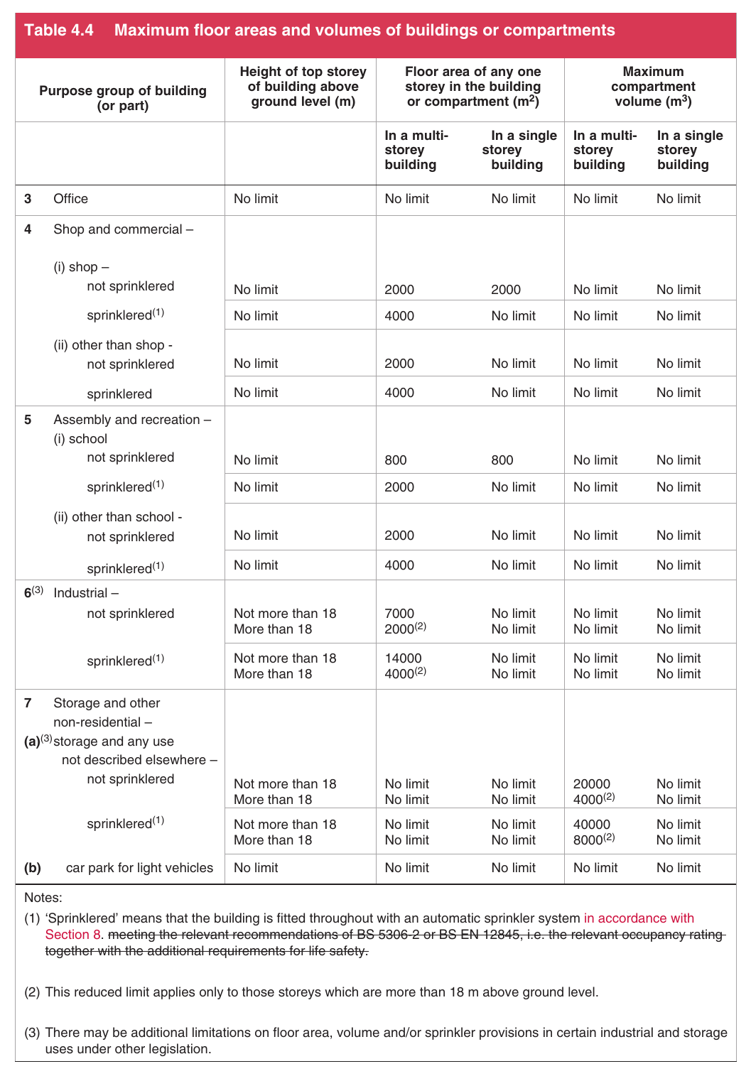
Page 107
#Source page 107
Junctions of compartment walls and compartment floors with other walls
4.20Where a compartment wall or compartment floor meets a compartment wall or an external wall the junction should maintain the fire resistance for a period of not less than the period of fire resistance required by the compartment wall or compartment floor.
Junction of compartment walls and roofs
4.21If a fire penetrates a roof near a compartment wall there is a risk that it will spread over the roof to the adjoining compartment. Where a compartment wall meets a roof it should –
(a) where the roof covering has a designation of AA, AB or AC (see paragraph 5.21), on a substrate or deck of a material of limited combustibility, for a width of not less than 1.5 m on either side of the junction – be taken up to meet the underside of the roof covering or deck and the junction fire-stopped [see Diagram 4.2(a)]. Where double skinned insulated roof sheeting is used it should incorporate a firebreak formed by a band of material of limited combustibility not less than 300 mm wide centred over the wall.
Note – Thermoplastic rooflights which by virtue of paragraph 5.25 are regarded as having an AA (National class) designation or BROOF(t4) (European class) are not suitable for use in the zone described above.
However, where the building is of Purpose Group 1, 2(b), 3 or 5 and is not more than 15 m in height a combustible substrate of timber boarding, wood wool slabs or timber tiling battens may be carried over the compartment wall provided it is fully bedded in mortar, or no less suitable material, over the entire width of the wall [see Diagram 4.2(b)]; or
(b) be extended up through the roof to a height of not less than 375 mm above the top surface of the roof covering [see Diagram 4.2(c)].
In paragraph (a) where roof support members pass through the wall they should be fire protected for a length of not less than 1.5 m on either side of the wall in order to avoid distortion at the junction.
Openings in compartment walls which separate buildings or occupancies
4.22A compartment wall which is common to two or more buildings, or which separates different occupancies in the same building, should have no openings other than those for –
(a)means of escape in case of fire – when a fire-resisting self-closing door (see paragraphs 4.29 to 4.35) having the same period of fire resistance as that of the compartment wall should be provided; and
(b)the passage of a pipe – when the opening in the wall should comply with paragraphs 4.43 and 4.45 to 4.47.
Page 108
#Source page 108
Diagram 4.2 Junction of compartment wall and roof
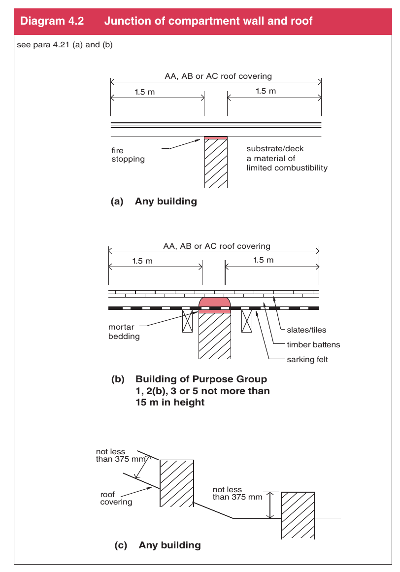
Page 109
#Source page 109
Openings in other compartment walls and in compartment floors
4.23A compartment wall (other than one described in paragraph 4.22) and a compartment floor should have no openings other than those –
(a)having a fire-resisting self-closing door (see paragraph 4.29 to 4.35);
(b)for the passage of pipes, ventilation ducts, chimneys, appliance ventilation duct or duct encasing one or more flue pipes – when the opening in the compartment wall or compartment floor should comply with paragraphs 4.43 to 4.47;
(c)for a waste chute system constructed of non-combustible materials;
(d)for an atrium designed in accordance with the relevant recommendations of BS 9999 BS 5588-7; and
(e)for a protected shaft which complies with the provisions of paragraph 4.25 to 4.28.
4.24The combined width of openings for fire doors in a compartment wall should be not more than 25% of the length of the compartment wall.
Protected shafts between compartments
4.25A protected shaft should only be used to accommodate stairs, lifts, escalators, chutes, ducts, pipes, sanitary accommodation and washrooms. Where a protected shaft contains a protected stairway, Section 2 imposes additional requirements (see paragraphs 2.69 to 2.73) and where it contains a firefighting stairway Section 6 imposes additional requirements (see paragraphs 6.3 to 6.6).
The construction enclosing a protected shaft, other than a wall which is part of an external wall, should –
(a)form a complete barrier to fire between the different compartments which the shaft connects;
(b)have the same fire resistance as the compartment through which it is passing, other than where a glazed screen complying with paragraph
4.26is provided; and
(c)satisfy the provisions regarding ventilation in paragraph 4.27 and regarding the treatment of openings in paragraph 4.28.
Glazed screens in protected shafts
4.26Glazing may be incorporated in the wall between a protected shaft containing a stairway, and a corridor or lobby which gives access to that stairway provided that –
(a)the protected shaft is not a firefighting shaft;
(b)the protected shaft is not required to have more than 60 minutes fire resistance; and
(c)the glazing has not less than 30 minutes fire resistance in respect of integrity; and either –
(i)the glazing is limited in extent in accordance with Table 2.8; or
(ii)the corridor or lobby has not less than 30 minutes fire resistance (see Diagram 4.3).
Page 110
#Source page 110
Diagram 4.3 Glazed screen separating protected shaft from corridoror lobby
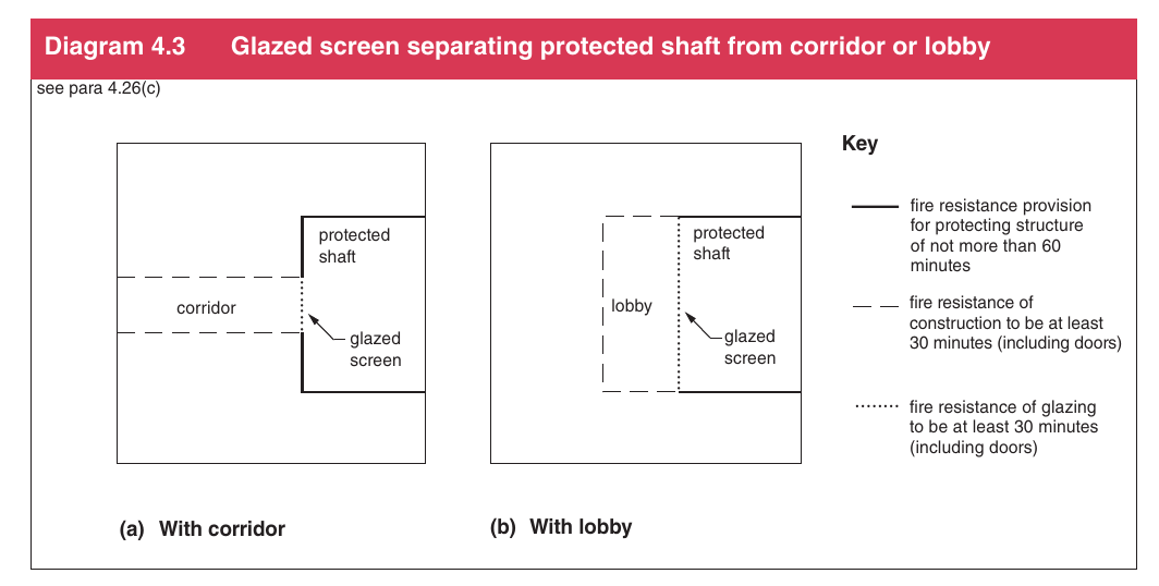
Pipes for oil or gas and ventilation ducts in protected shafts
4.27Where a protected shaft contains –
(a)a stairway and/or a lift it should not contain –
(i)a pipe conveying oil, other than in the mechanism of a hydraulic lift; or
(ii)a ventilation duct, other than a duct provided for the purposes of pressurizing the shaft to keep it free from smoke in the event of fire or a duct provided solely for ventilating the stairway; and
(b)a pipe conveying flammable gas it should be adequately ventilated directly to external air by ventilation openings at both high and low levels in the shaft. Any pipe conveying natural gas or LPG should be of screwed steel or of all welded steel construction.
Openings in protected shafts
4.28(a) Where the wall of a protected shaft is common to two or more buildings no opening should be provided in that wall other than for –
(i)means of escape in case of fire – when a fire-resisting self-closing door, having the same period of fire resistance as the protected shaft, should be provided; and
(ii)the passage of a pipe – when the opening should comply with paragraphs 4.43 and 4.45 to 4.47.
Page 111
#Source page 111
(b) Other than in walls subject to sub-paragraph (a) and external walls, a protected shaft should only have openings for –
(i)a fire-resisting self-closing door which complies with paragraph 4.29;
(ii)the passage of a pipe where the opening complies with paragraphs 4.43 and 4.45 to 4.47;
(iii) where the shaft is or contains a ventilation duct – the inlets to, outlets from and opening for a ventilation duct which complies with paragraph 4.44;
(iv)where the shaft is pressurized for the purposes of paragraph
2.64– the inlet from and opening for the ductwork; and
(v)where the shaft contains a lift – the passage of lift cables into a lift motor room. Where the motor room is at the bottom of the shaft the opening should be as small as practicable.
Fire doors
4.29A fire door should have the performance appropriate to the location given in Table 4.5 and should be fitted with an automatic self-closing device (other than those fire doors to cupboards and ducts, which are to be kept locked shut when not in use).
4.30(a) Under National determination fire doors are classified by their performance under test to BS 476: Part 22 in respect of integrity expressed in minutes. A suffix (S) is added for doors where smoke leakage at ambient temperatures is to be restricted.
(b)Under European determination fire doors are classified by their performance with reference to Commission Decision 2000/367/EC of 3rd May 2000 implementing Council Directive 89/106/EEC as regards the classification of the resistance to fire performance of construction products, construction works and parts thereof. All fire doors should be classified in accordance with BS EN 13501-2 Fire classification of construction products and building elements – Part 2: Classification using data from fire resistance and/or smoke control tests, excluding ventilation services. Performance in respect of integrity (E) is expressed in minutes. An additional classification of ‘Sa’ is used where smoke leakage at ambient temperatures is to be restricted. The fire resistance tests are –
(i)BS EN 1634-1 Fire resistance and smoke control tests for door, shutter and openable window assemblies and elements of building hardware – Part 1: Fire resistance tests for doors, shutters and openable windows;
(ii)BS EN 1634-2 Fire resistance and smoke control tests for door, shutter and openable window assemblies and elements of building hardware – Part 2: Fire resistance characterisation test for elements of building hardware;
(iii) BS EN 1634-3 Fire Resistance tests for door and shutter assemblies – Part 3: Smoke control doors and shutters; and
(iv) BS EN 81-58 Safety rules for the construction and installation of lifts
– Examination and tests – Part 58: Landing doors fire resistance test, which may be used for lift landing doors in accordance with European Parliament Council Directive 95/16/EC of 29/06/1995 implementing the Lifts Regulations 1997.
Page 112
#Source page 112
Table 4.5 Performance of fire doors
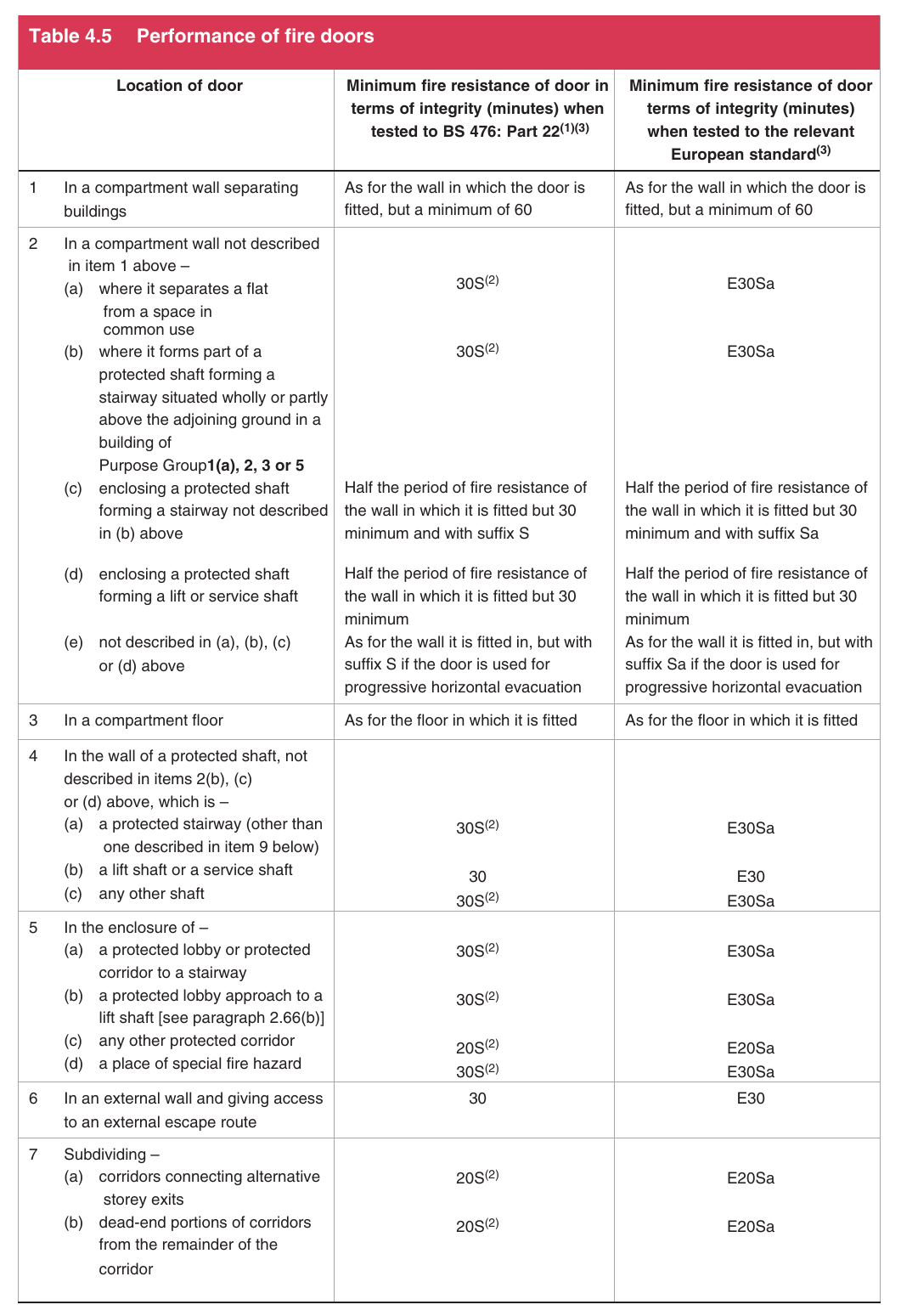
Page 113
#Source page 113
Table 4.5 Performance of fire doors (cont’d)
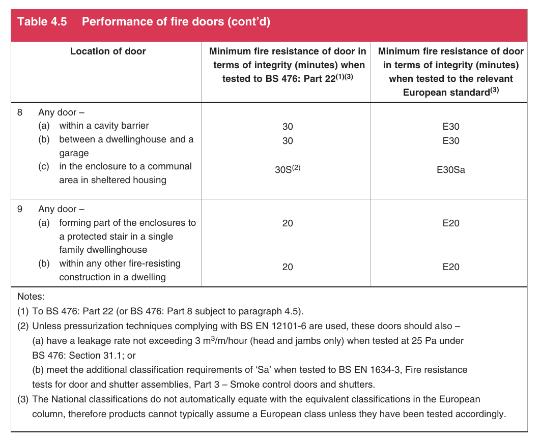
4.31The method of test exposure is from each side of the door separately, except in the case of lift doors, which are tested from the landing side only.
Any test evidence used to substantiate the fire resistance rating of a door or shutter should be carefully checked to ensure that it adequately demonstrates compliance and is applicable to the complete installed assembly. Small differences in detail (such as glazing aperatures, intumescent strips, door frames and ironmongery etc.) may significantly affect the rating.
4.32A fire door should only be held open by –
(a)a fusible link, provided that the provisions of paragraph 4.34 are complied with where the door opening is provided for means of escape;
(b)an automatic release mechanism complying with BS 5839-3 provided that –
(i)the release mechanism is activated by an automatic fire detection and fire alarm system to BS 5839-1 of at least Category L5 standard with a smoke detector located on either side of the door;
(ii)the door can be closed manually; and
(iii)the door does not give access to a firefighting stairway; or
Page 114
#Source page 114
(c)a door co-ordinator device which co-ordinates the closing sequence of rebated double leaf swing doors.
4.33Unless shown to be satisfactory when tested as part of a fire door assembly, the hinges on which a fire door is hung should be made from material having a melting point of at least 800ºC.
4.34Where an opening is provided for, or opens onto, a means of escape and it is intended that the door should be held open by a fusible link, a second door having 30 minutes fire resistance should be provided. This second door should be capable of closing the opening and be easily opened by hand.
Where two fire doors are fitted in the same opening and each door is capable of closing that opening, the total fire resistance may be taken as the sum of their individual fire resistance.
4.35All fire doors, other than those listed below, should be marked with an appropriate fire safety sign complying with BS 5499: Part 1 indicating whether the door is –
(a)to be kept closed when not in use;
(b)to be kept locked shut when not in use; or
(c)held open by an automatic release mechanism.
Signs should be provided on both sides of the door except for doors to cupboards and service ducts which should be marked on the outside only.
The following fire doors do not require to be marked –
(i)doors within dwellinghouses;
(ii)doors to and within flats;
(iii) bedroom doors in Purpose Group 2 buildings; and
(iv) lift doors.
Provision of cavity barriers
#Source page 115
4.36To restrict the spread of smoke and flame through concealed spaces in the construction of a building, cavity barriers should be provided –
(a) in a building of any purpose group –
(i)at the intersection of fire-resisting construction and an element containing a cavity as shown in Diagram 4.4; and
(ii)as set out in Table 4.6 for the appropriate purpose group of the building and the specified locations.
[Note – alternative arrangements for items 1, 3 and 4 are shown in Diagram 4.5 and for item 2 in Diagram 4.6. Notes (3) and (4) to Table 4.6 are supported by Diagrams 4.7 and 4.8 respectively]; and
(b) in a building of Purpose Group 2, 3, 4, 5, 6 or 7 – so that the maximum dimension of a cavity, (other than one described in paragraph 4.40 or 4.41) should be not greater than that given in Table 4.7 for the appropriate location of the cavity.
4.37A cavity barrier should not be used above a compartment wall to complete the line of compartmentation, i.e. a compartment wall should be carried up to a compartment floor or to a roof.
Table 4.6 Provision of cavity barriers
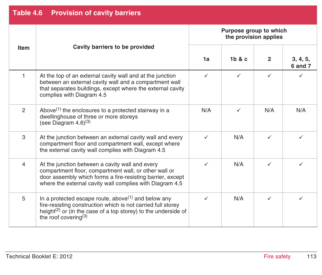
Page 116
#Source page 116
Table 4.6 Provision of cavity barriers (cont’d)
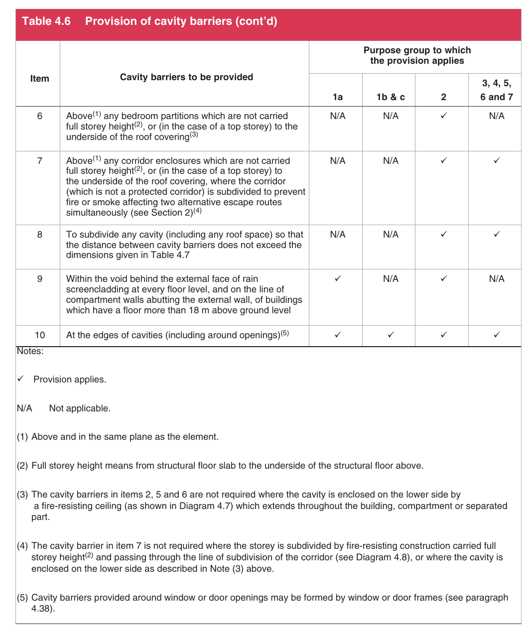
Page 117
#Source page 117
Diagram 4.4 Cavity barriers at intersections
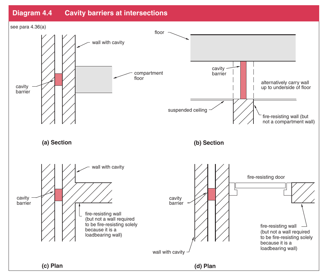
Page 118
#Source page 118
Diagram 4.5 Cavity walls excluded from certain provisions for cavity barriers
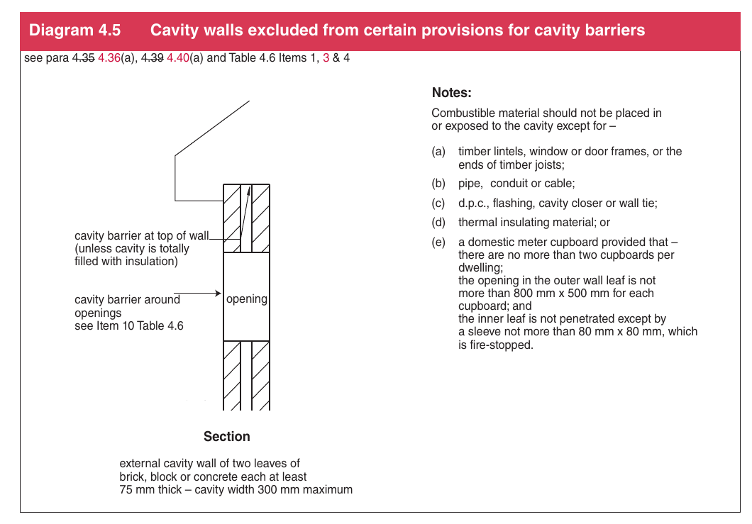
Diagram 4.6 Alternative arrangement of cavity barriers in roof space over a protected stairway in a dwellinghouse of three or more storeys
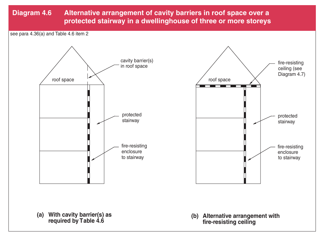
Page 119
#Source page 119
Diagram 4.7 Fire-resisting ceiling below a cavity
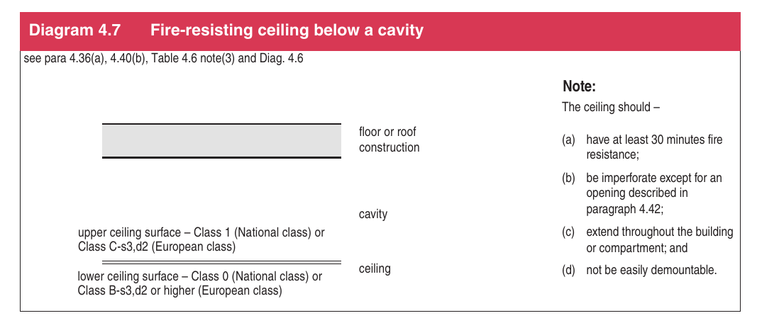
Diagram 4.8 Alternative arrangements for corridor enclosure
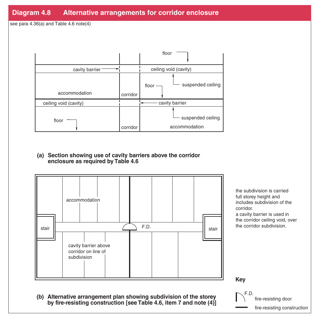
Page 120
#Source page 120
Construction of cavity barriers
4.38A cavity barrier should be constructed to provide fire resistance of not less than 30 minutes in respect of integrity and 15 minutes in respect of insulation (see item 15 of Table 4.1), however, a cavity barrier in a stud partition or wall may be formed of –
(a)steel at least 0.5 mm thick;
(b)timber at least 38 mm thick;
(c)polyethylene sleeved mineral wool or mineral wool slab, in either case under compression when installed in the cavity; or
(d)calcium silicate, cement based or gypsum based boards at least 12 mm thick.
A cavity barrier may be formed by any construction provided for another purpose if that construction meets the provisions for a cavity barrier.
4.39A cavity barrier should be tightly fitted and fixed in position. Where this is not possible, e.g. in the case of a junction with slates or profiled sheeting, the junction should be fire-stopped in accordance with paragraphs 4.45 to 4.47.
The fixing of a cavity barrier should be such that the performance of the cavity barrier is unlikely to be made ineffective by –
(a)the movement of the building due to subsidence, shrinkage or thermal change and movement of the external envelope due to wind;
(b)the collapse in a fire of any service which penetrates it;
(c)the failure in a fire of its fixings or supporting structure; and
(d)the failure in a fire of any material or construction which the cavity barrier abuts, e.g. if a cavity barrier is connected to a suspended ceiling, collapse of the ceiling should not cause premature failure of the cavity barrier.
Cavities not requiring subdivision
4.40The provisions of paragraph 4.36(b) should not apply to a cavity which is –
(a)in a masonry or concrete external cavity wall complying with Diagram 4.5;
(b)in a floor void or in a roof void where the cavity does not exceed 30 m in extent and is enclosed on its lower side by a fire-resisting ceiling (complying with Diagram 4.7) which extends throughout the building or compartment;
(c)below a floor next to the ground where the cavity is not greater than 1 m in height or is not normally accessible by people. However, this should not apply where there is any opening in the floor such that it is possible for combustible material to accumulate in the cavity (in this case cavity barriers and access for cleaning should be provided);
(d)formed behind the external skin in rain-screen external wall construction, or by over-cladding an existing masonry or concrete external wall or an existing concrete roof, provided that the cavity does not contain combustible insulation and the provisions of Table 4.6 Item 9 are complied with; and
Page 121
#Source page 121
(e)between double-skinned, profiled, insulated, roof sheeting provided that –
(i)the sheeting is a material of limited combustibility;
(ii)both surfaces of the insulation layer have a surface spread of flame classification not lower than Class 1 (National class) or Class C-s3,d2 (European class); and
Diagram 4.9 Provision of cavity barriers in double-skinned profiled insulated roof sheeting
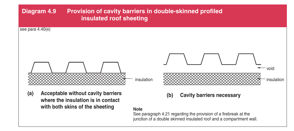
(iii) the insulation is in contact with the inner and outer skins of sheeting as shown in Diagram 4.9(a).
4.41Where the cavity is over an undivided room which –
(a)exceeds the appropriate maximum dimension for a cavity in Table 4.7, cavity barriers need only be provided on the line of the enclosing walls of that room, provided that they are not more than 40 m apart and that the surfaces exposed in the cavity are not lower than Class 1 (National class) or Class C-s3,d2 (European class); or
(b)exceeds 40 m (in either direction on plan), cavity barriers need not be provided where –
(i)the room and the cavity together are compartmented from the rest of the building;
(ii)an automatic fire detection and fire alarm system complying with BS 5839-1 is fitted in the building;
(iii) the surface of the ceiling exposed in the cavity is of Class 0 (National class) or Class B-s3,d2 or higher (European class) and the ceiling supports and fixings in the cavity are of non-combustible construction;
(iv)the surface spread of flame classification of any pipe insulation in the cavity is not lower than Class 1 (National class) or Class C-s3,d2 (European class);
(v)any electrical wiring in the cavity is laid in metal trays or in metal conduit;
(vi)any other material in the cavity is a material of limited combustibility; and
Page 122
#Source page 122
(vii) where the cavity is used as a plenum – the relevant recommendations of BS 9999 5588-9 in relation to recirculating air distribution systems are complied with.
Table 4.7 Maximum dimension of a cavity in Purpose Group 2, 3, 4, 5, 6 and 7 buildings (1)
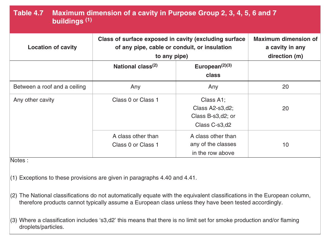
Openings in cavity barriers
4.42There should be no openings in a cavity barrier other than those for –
(a)a fire door which has not less than 30 minutes fire resistance and complies with paragraphs 4.29 to 4.35;
(b)the passage of a pipe which complies with paragraph 4.43;
(c)the passage of a cable, a conduit or tray containing one or more cables;
(d)an opening fitted with a suitably mounted automatic fire damper; and
(e)a duct which (unless it is fire-resisting) is fitted with a suitably mounted automatic fire damper where it passes through the cavity barrier.
Page 123
#Source page 123
Pipes penetrating fire separating elements
4.43Where a pipe passes through a fire separating element it should be –
(a)provided with a suitable proprietary sealing system which has been shown by test to maintain the fire resistance of the fire separating element; or
(b)where a proprietary sealing system is not used –
(i)of a diameter not more than the relevant nominal internal diameter given in Table 4.8, with the opening as small as is practicable and fire-stopped around the pipe; or
(ii)of lead, aluminium, aluminium alloy, fibre-cement or uPVC, having a maximum internal diameter not more than 160 mm and be within a non-combustible sleeve [see Table 4.8 Note (1)] as shown in Diagram 4.10.
Ventilation ducts penetrating fire separating elements
4.44Where a ventilation or air conditioning duct passes through a fire separating element it should comply with an appropriate method for maintaining the fire resistance of the wall, floor or barrier given in BS 5588-9 the relevant recommendations of BS 9999.
Fire dampers should be tested to BS EN 1366-2 and be classified to BS EN 13501-3. They should have an E classification not less than 60 minutes. Fire and smoke dampers should also be tested to BS EN 1366-2 and be classified to BS EN 13501-3. They should have an ES classification not less than 60 minutes.
Diagram 4.10 Pipes penetrating fire separating elements
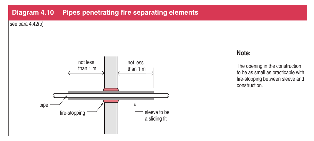
Page 124
#Source page 124
Table 4.8 Maximum nominal internal diameter of pipes passing through fire separating elements
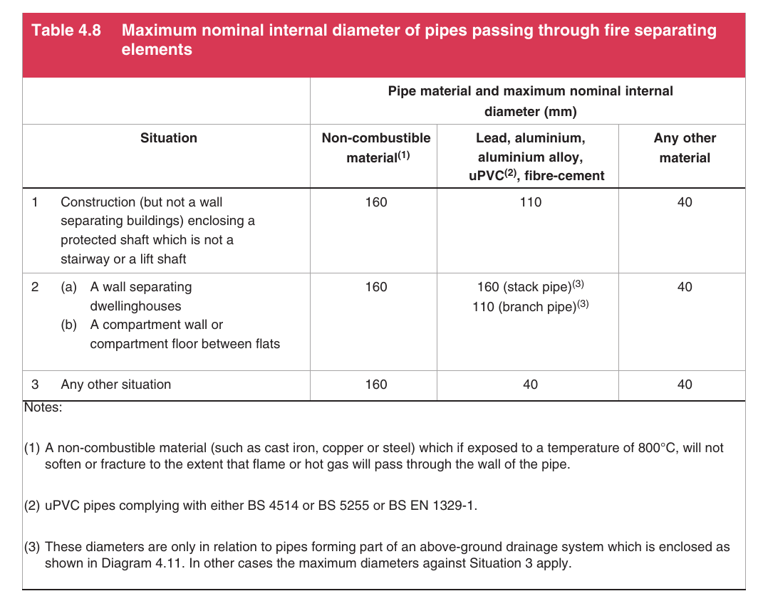
Fire-stopping
4.45In addition to any other provision in this Technical Booklet for fire-stopping, fire-stopping should be provided at –
(a)all joints and imperfections of fit between elements which serve as a barrier to the passage of fire; and
(b)all openings for pipes, ducts, cables, conduits or trays which pass through any fire separating element, and such openings should be –
(i)as few in number as possible; and
(ii)as small as is practicable.
4.46To prevent the displacement of fire-stopping it should be supported by, or reinforced with, a material of limited combustibility –
(a)where it is a non-rigid material (unless it has been shown by test not to require such support or reinforcement); and
(b)in all locations where its unsupported span is more than 100 mm.
4.47In addition to proprietary fire-stopping and sealing systems, which have been shown by test to be suitable, the following materials may be suitable as fire-stopping in situations appropriate to the particular material –
(iii) cement or gypsum based vermiculite/perlite mixes;
#Source page 125
(i)cement mortar;
(ii)gypsum based plaster;
(iii) cement or gypsum based vermiculite/perlite mixes;
(iv)glass fibre, crushed rock, blast furnace slag or ceramic based products (with or without resin binders); and
(v)intumescent mastics.
Flues and heating appliance ventilation ducts penetrating compartment walls and compartment floors
4.48 Where a flue, a duct containing more than one flue, or an appliance ventilation duct –
(a)passes through a compartment floor or compartment wall; or
(b)is built into a compartment wall,
the walls enclosing the flue or duct should have a period of fire resistance of not less than half that required for the compartment wall or compartment floor and be of non-combustible construction, as shown in Diagram 4.12.
Diagram 4.11 Enclosure for drainage or water supply pipes
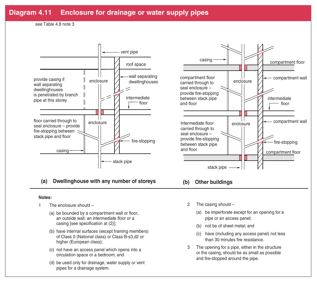
Page 126
#Source page 126
Diagram 4.12 Flues in compartment walls and compartment floors
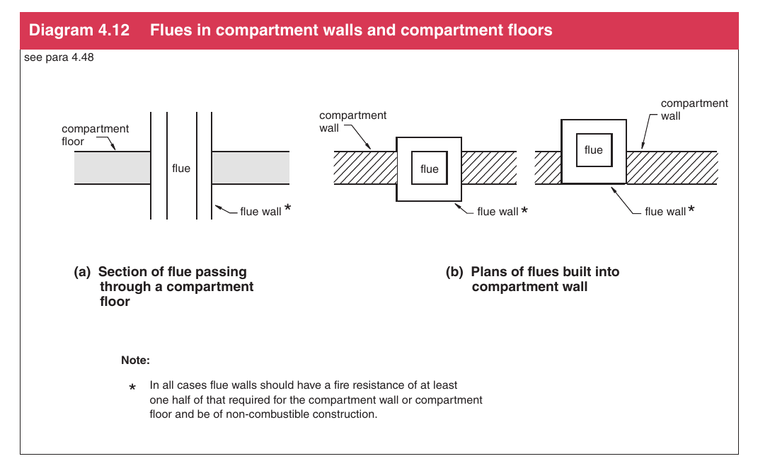
Page 127
#Source page 127
Car parks for light vehicles
4.49All materials used in the construction of a building, separated part or compartment used for car parking should be non-combustible other than –
(a)a surface finish which meets the relevant provisions of Sections 3 and 5 which –
(i)is applied to a floor or roof of the car park; and
(ii)is applied within any adjoining building, separated part or compartment – to the structure enclosing the car park;
(b)a fire door;
(c)an attendant’s kiosk which does not exceed 15 m2 in area; and
(d)any shop mobility facility which does not exceed 30 m2 in floor area.
Open-sided car parks
4.50A car park may be regarded as an open-sided car park for the purposes of Table 4.2 [i.e. Purpose Group 7(b)(i)] where, in addition to complying with paragraph 4.49 –
(a)it has no basement storeys;
(b)it is naturally ventilated by permanent openings, at each car parking level, having an aggregate ventilation area of not less than 5% of the floor area at that level, with not less than half that ventilation area equally divided in two opposing walls and distributed to provide effective cross-ventilation; and
(c)where the building is also used for any other purpose – that part forming the car park is a separated part.
Car parks which are not open-sided
4.51Where a car park does not comply with the provisions of paragraph 4.50 it should not be regarded as open-sided for the purposes of Table 4.2 [i.e. it falls in Purpose Group 7(b)(ii)]. However, there is a need for ventilation in such a car park, therefore in addition to the provisions of paragraph 4.49 it should have either –
(a)natural ventilation at each storey –
(i)by permanent openings at each car parking level, having an aggregate ventilation area of not less than 2.5% of the floor area at that level, with not less than half that ventilation area equally divided in two opposing walls and distributed to provide effective cross-ventilation; or
(ii)by suitable vents at ceiling level on each car parking level having an aggregate area of permanent opening not less than 2.5% of the floor area and so arranged as to have a through flow of air; or
Page 128
#Source page 128
(b)a system of mechanical ventilation where –
(i)the system is independent of any other ventilation system and designed to operate at 6 air changes per hour for normal extraction and at 10 air changes per hour in a fire condition;
(ii)the system is designed to operate in two parts, each capable of extracting 50% of the rates set out in (i) above and designed so that each part may operate singly or simultaneously; each part of the system should have an independent power supply which will operate in the event of failure of the main supply;
(iii) extract points are arranged so that 50% are at high level and 50% at low level; and
(iv) the fans are rated to run at 300ºC for not less than 60 minutes, and the ductwork and fixings are constructed of materials having a melting point of not less than 800ºC.
(See Technical Booklet K for guidance on normal ventilation of car parks.)
Page 129
#Source page 129
Shopping complexes
4.52Whilst the provisions in this Technical Booklet about shops should generally be capable of application in cases where a shop is contained in a single separated building, the provisions may not be appropriate where a shop forms part of a complex. These may include covered malls providing access to a number of shops and common servicing areas. In particular, the provisions about maximum compartment size may be difficult to meet, bearing in mind that it would generally not be practical to compartment a shop from a mall serving it. (To a lesser extent, the provisions about fire resistance, walls separating shop units, surfaces and boundary distances may also pose problems.)
4.53To ensure a satisfactory standard of fire safety in shopping complexes, alternative measures and additional compensatory features to the provisions set out in this Section are needed. Such features are set out in Sections 5 and 6 of BS 5588-10 and the relevant recommendations of BS 9999 those sections and should be followed.
Page 130
#Source page 130
Insulating core panels used for internal structures
4.54Insulating core panel systems are used for external cladding as well as for internal structures. However, whilst both types of panel system have unique fire behaviour characteristics, it is those used for internal structures that can present particular problems with regard to fire spread.
The most common use of insulating core panels, when used for internal structures, is to provide an enclosure in which a chilled or sub zero environment can be generated for the production, preservation, storage and distribution of perishable foodstuffs. However, this type of construction is also used in many other applications, particularly where the maintenance of a hygienic environment is essential.
These panels typically consist of an inner core sandwiched between, and bonded to facings of galvanised steel, often with a PVC facing for hygiene purposes. The panels are then formed into a structure by jointing systems, usually designed to provide an insulating and hygienic performance. The panel structure can be free standing, but is usually attached to the building structure by lightweight fixings or hangers in the case of ceilings.
The most common forms of insulation in present use are polyisocyanurate, mineral fibre, phenolic, polystyrene (cold stores), extruded polystyrene and composite polymers such as syntactic phenolic.
Fire behaviour of the core materials and fixing systems
4.55The degradation of polymeric materials can be expected when exposed to radiated/conducted heat from a fire, with the resulting production of large quantities of smoke. It is recognised that the potential for problems in fires involving mineral fibre cores is less than those for polymeric core materials.
In addition, irrespective of the type of core material, the panel, when exposed to the high temperatures of a developed fire, will tend to delaminate between the facing and core material, due to a combination of expansion of the metal facing and softening of the bond line.
Therefore once it is involved, either directly or indirectly in a fire, the panel will have lost most of its structural integrity. Stability will then be dependant on the method of fixing to the structure. For systems that are not fixed through both facings the stability of the system will then depend on the residual structural strength of the non-exposed facing, the interlocking joint between panels and the fixing system.
Most jointing or fixing systems for these systems have an extremely limited structural integrity performance in developed fire conditions. If the fire starts to heat up the support fixings or structure to which they are attached, then there is a real chance of total collapse of the panel system.
Where panels are used as the lining to a building the insulating nature of these panels, together with their sealed joints, means that fire can spread behind the panels, hidden from the occupants of occupied rooms/spaces. With some thermoplastic cores fire can also spread between the panel facings.
Page 131
#Source page 131
This can prove to be a particular problem to firefighters as, due to the insulating properties of the cores, it may not be possible to track the spread of fire, even using infra red detection equipment. This difficulty, together with that of controlling the fire spread within and behind the panels, is likely to have a detrimental effect on the performance of the fixing systems, potentially leading to their complete and unexpected collapse, together with any associated equipment.
Firefighting
4.56When compared with other types of construction techniques, these panel systems therefore provide a unique combination of problems for firefighters, including –
(a)hidden fire spread within panels with thermoplastic cores;
(b)production of large quantities of black toxic smoke and rapid fire spread leading to flashover; and
(c)hidden fire behind lining systems.
These three characteristics are common to both polyurethane and polystyrene cored panels, although the rate of fire spread in polyurethane cores is significantly less than that of polystyrene cores, especially when any external heat source is removed.
In addition, irrespective of the type of panel core, all systems are susceptible to delamination of the steel facing, collapse of the system and hidden fire spread behind the system.
Design recommendations
4.57To identify the appropriate solution, a risk assessment approach should be adopted. This would involve identifying the potential fire risk within the enclosures formed by the panel systems and then adopting one or more of the following at the design stage –
(a)removing the risk;
(b)separating the risk from the panels by an appropriate distance;
(c)providing a fire suppression system for the risk;
(d)providing a fire suppression system for the enclosure;
(e)providing fire-resisting panels; and
(f)specifying appropriate materials/fixing and jointing systems.
In summary the performance of the building structure, including the insulating envelope, the superstructure, the substructure, etc., must be considered in relation to their performance in the event of a fire.
Page 132
#Source page 132
Specifying panel core materials
4.58Where at all possible the specification of panels with core materials appropriate to the application will help ensure an acceptable level of performance for panel systems, when involved in fire conditions. The following are examples in the provision of core materials which may be appropriate to the application concerned–
(a)Mineral fibre cores – cooking areas, hot areas, bakeries, fire breaks in combustible panels, fire stop panels and general fire protection.
(b)All cores – chill stores, cold stores, blast freezers, food factories and clean rooms.
Note – Core materials may be used in other circumstances where a risk assessment has been made and other appropriate fire precautions have been put in place.
Specifying materials/fixing and jointing systems
4.59The following are methods by which the stability of panel systems may be improved in the event of a fire, although they may not all be appropriate in every case.
(a)Insulating envelopes, support systems, and supporting structure should be designed to allow the envelope to remain structurally stable by alternative means such as catenary action following failure of the bond line between insulant core and facing materials. This particularly relates to ceilings and will typically require positive attachment of the lower faces of the insulant panels to supports.
(b)The building superstructure, together with any elements providing support to the insulating envelope, should be protected to prevent early collapse of the structure or the envelope.
•Note – Irrespective of the type of panel provided, it will remain necessary to ensure that the supplementary support method supporting the panels remains stable for an appropriate time period under fire conditions. It is not practical to fire protect light gauge steel members such as purlins and sheeting rails which provide stability to building superstructures and these may be compromised at an early stage of a fire. Supplementary fire-protected heavier gauge steelwork members could be provided at wider intervals than purlins to provide restraint in the event of a fire.
(c)In designated high risk areas, consideration should be given to incorporating non-combustible insulant cored panels into wall and ceiling construction at intervals, or incorporating strips of non- combustible material into specified wall and ceiling panels, in order to provide a barrier to fire propagation through the insulant.
(d)Correct detailing of the insulating envelope should ensure that the combustible insulant is fully encapsulated by non-combustible facing materials which remain in place during a fire.
(e)The panels should incorporate pre-finished and sealed areas for penetration of services.
Page 133
#Source page 133
In addition, the details of construction of the insulating envelope should, particularly in relation to combustible insulant cores, prevent the core materials from becoming exposed to the fire and contributing to the fire load.
General
4.60Generally panels or panel systems should not be used to support machinery or other permanent loads.
Any cavity created by the arrangement of panels, their supporting structure or other building elements should be provided with suitable cavity barriers.
Examples of possible solutions and general guidance on insulating core panels construction can be found in the relevant chapters of the Design, construction, specification and fire management of insulated envelopes for temperature controlled environments published by the International Association of Cold Storage Contractors (European Division).
Page 134
#Source page 134
Section 5 External fire spread
5.1This Section contains provisions relating to the design and construction of –
(a)external walls in order that –
(i)the risk of ignition from an external source to the outside surface of a building; and, the spread of flame over the external surface is restricted; and
(ii)the materials used to construct external walls and attachments to them and how they are assembled do not contribute to the rate of fire spread up the outside of a building; and
(iii)the spread of fire from one building to another is restricted; and
(b)roofs – in order that the risk of spread of flame and of fire penetration from an external source are restricted.
Fire resistance of external walls
5.2The external walls of a building are elements of structure and other than those areas which may be unprotected (as determined in accordance with paragraphs 5.10 to 5.12) should have the appropriate period of fire resistance given in Section 4.
Combustibility of external walls
5.2A The external walls of a building should not provide a medium for fire spread if that is likely to be a risk to health and safety. Combustible materials, cavities in external walls and attachments to external walls can present such a risk, particularly in tall buildings. The guidance in this section is designed to reduce the risk of vertical fire spread in all buildings and the risk of ignition from external sources.
5.2B The external walls of buildings other than those described in Regulation 23(4) of the Building Regulations should achieve all the provisions given in paragraphs 5.3 to 5.4B which provide guidance on all of the following –
(i)external surfaces;
(ii)materials and products; and
(iii) cavities and cavity barriers;
External Surfaces
5.3The external surface of an external wall (i.e. outermost external material) should meet the requirements given in Table 5.1A relevant to the height of the building and the distance between the building and the relevant boundary.
Page 135
#Source page 135
Materials and Products
5.4Where a building has a storey the floor of which is 18 m or more above ground level, any insulation material, and any filler material (such as the core materials of metal composite panels, sandwich panels and window spandrel panels but not including gaskets, sealants and similar) used in the construction of an external wall should be Class A2-s3, d2 or better. This restriction does not apply to masonry cavity wall construction which complies with Diagram 4.5 in Section 4. Where Regulation 23(2) applies, that regulation prevails over all the provisions in this paragraph.
Note 1: Best practice guidance for green walls (also called living walls) can be found in Fire performance of Green Roofs and Walls.
Cavities and cavity barriers
5.4A Cavity barriers should be provided in accordance with paragraphs 4.36 to 4.42.
5.4B In the case of an external wall construction, of a building which, by virtue of paragraph 4.40(d) (external cladding system with a masonry or concrete inner leaf), is not subject to the provisions of Table 4.7, the surfaces which face into cavities should also meet the provisions of Table 5.1A, and provisions for cavity barriers in Section 4, but where Regulation 23(2) applies, that regulation prevails over guidance provided in Table 5.1A and Section 4.
Page 136
#Source page 136
| Table 5.1A Reaction to fire performance of external surface of walls | |||
|---|---|---|---|
| Building Type | Building height | Less than 1m from the relevant boundary | 1m or more from the rele- vant boundary |
| ‘Relevant buildings’ as defined in regulation 23(4) | Class A2-s1,d0 (1) or better | Class A2-s1, d0 (1) or better | |
| Assembly and recreation | More than 18m | Class B-s3, d2 (2) or better | From ground level to 18m: class C-s3, d2 (3) or better From 18m in height and above: class B-s3, d2 (2) or better |
| 18m or less | Class B-s3,d2 (2) or better | Up to 10m above ground level: class C-s3,d2 (3) or better Up to 10m above a roof or any part of the building to which the public have access: class C-s3, d2 (3) or better (4) From 10m in height and above: Class E-d2 or better | |
| Any other building | More than 18m | Class B-s3, d2 (2) or better | From ground level to 18m: class C-s3, d2 (3) or better From 18m in height and above: class B-s3, d2 (2) or better |
| 18m or less | Class B-s3, d2 (2) or better | Class E-d2 or better | |
| Notes: In addition to the requirements within this table, buildings with a top occupied storey above 18m should also meet the provisions of paragraph 5.4. (1) The restrictions for these buildings apply to all the materials used in the external wall and specified attachments (see paragraphs 5.4C to 5.4F for further guidance). (2) Profiled or flat steel sheet at least 0.5mm thick with an organic coating of no more than 0.2mm thickness is also acceptable. (3) Timber cladding at least 9mm thick is also acceptable. (4) 10m is measured from the top surface of the roof. |
.
Page 137
#Source page 137
Regulation 23(2)
Materials
5.4C Regulation 23(1) requires that materials used in building work are appropriate for the circumstances in which they are used. Regulation 23(2) sets requirements in respect of external walls and specified attachments in relevant buildings.
Note: Guidance on Regulation 23(1) can be found in Technical Booklet B.
5.4D Regulation 23(2) applies to any building with a storey at least 18m above ground level and which contains one or more dwellings; an institution; or a room for residential purposes (excluding any room in a hostel, hotel or a boarding house). It requires that all materials which become part of an external wall or specified attachment achieve European Class A2-s1, d0 or Class A1, other than those exempted by Regulation 23(3).
Note 1: The above includes any building with a storey at least 18m above ground level that contains student accommodation, care homes, nursing homes, sheltered housing, hospitals, dormitories in boarding schools and places of lawful detention.
Note 2: The requirement in Regulation 23(2) is limited to materials achieving European classification Class A2-s1, d0 or Class A1. Therefore materials achieving limited combustibility cannot be deemed to meet the requirement using an alternative classification method.
Note 3: Products given in the Commission Decision 96/603/EC as amended by 2000/605/EC and 2003/424/EC can be considered to be class A1 without testing. These products may be deemed to meet the requirement.
5.4E External walls and specified attachments are defined in Regulation 22 and these definitions include any parts of the external wall as well as balconies, solar panels and sun shading.
5.4F Regulation 23(3) provides an exemption for certain components found in external walls and specified attachments.
Material change of use
5.4G Regulation 8 provides that, where the use of a building is changed such that the building becomes a building described in Regulation 23(4), the construction of the external walls, and specified attachments must be investigated and where necessary work must be carried out to ensure they only contain materials achieving European Class A2-s1, d0 or Class A1, other than those exempted by Regulation 23(3).
Further considerations for relevant buildings
5.4H The provisions of Regulation 23 apply in addition to the requirements of regulation 36. Therefore for buildings described in Regulation 23(4), the potential impact of any products incorporated into or onto the external walls should be carefully considered with regard to their number, size, orientation and position. Particular attention is drawn to the following points–
(a) membranes used as part of the external wall construction should achieve a minimum classification of European Class B-s3, d0;
Page 138
#Source page 138
(b)internal linings should comply with the guidance provided in section 3.
(c)any part of a roof should achieve the minimum performance as
detailed in section 5;
(d) as per regulation 23(3), window and door frames and associated glass (including laminated glass) are exempted from regulation 23(2).
Window spandrel panels and infill panels must comply with regulation 23(2);
(e) thermal breaks are small elements used as part of the external wall construction to restrict thermal bridging. There is no minimum performance for these materials. However, they should not span two compartments and should be limited in size to the minimum required to restrict the thermal bridging (the principal insulation layer is not to be regarded as a thermal break);
(f) regulation 23(2) applies to specified attachments. Shop front signs and similar attachments are not covered by the requirements of regulation
23(2), although attention is drawn to paragraph (g); and
(g) whilst regulation 23(2) applies to materials which become part of an external wall or specified attachment, consideration should be given to other attachments to the wall which could impact on the risk of fire spread over the wall.
Portal frames
5.5Frequently, the provisions of Section 4 do not require the portal frames of a single storey building to have fire resistance except where the column members of those frames are within, or support, an external wall, which under paragraph 5.2, is required to have fire resistance. Where this occurs both the column and rafter members should have fire resistance, as the moment-resisting connections mean the portal frame acts as a single element. However, in the case of a steel portal frame which has been designed in accordance with the method set out in Fire and steel construction: Single Storey Steel Framed Buildings in Fire Boundary Conditions, only those members within or supporting an external wall requiring fire resistance, need have fire resistance.
Page 139
#Source page 139
Space separation – External walls
5.6Protection against the external spread of fire from one building to another is related to –
(i)the distance between a building and each of its relevant boundaries (see paragraph 5.9); and
(ii)the extent of the unprotected area in the side of the building which faces that boundary.
The basic provisions are outlined in paragraph 5.13 and methods of meeting those provisions are given in paragraphs 5.14 to 5.19.
The provisions are based on a number of assumptions, and whilst some of these may differ from the circumstances of a particular case, together they enable a reasonable standard of space separation to be achieved.
The provisions limit the extent of openings and other unprotected areas in the sides of a building (including areas with a combustible surface) which would not give adequate protection against the external spread of fire from one building to another.
The assumptions for establishing space separation are –
(a)that the fire will involve a complete compartment but will not spread to other compartments;
(b)that the intensity of a fire is related to the use of the building and will be moderated by a sprinkler system where it is provided;
(c)that a building, which has an identical elevation, is located on the opposite side of, and at the same distance from, the relevant boundary; and
(d)that radiation from that part of the external wall, which has the fire resistance required by Section 4, is discounted unless its external surface is combustible as described in paragraph 5.10.
5.7Where a reduced separation distance is desired it may be advantageous to construct compartments of a smaller size.
Boundaries
5.8The use of the distance to a boundary rather than to another building, in measuring the separation distance, makes it possible to calculate the allowable proportion of unprotected areas, regardless of whether there is a building on an adjoining site, and regardless of the location of that building, and the extent of any unprotected areas that it might have.
Usually only the distance to the actual boundary of the site needs to be considered. But in some circumstances, when the site boundary adjoins a space where further development is unlikely, such as a road, then part of the adjoining space may be included as falling within the relevant boundary for the purposes of this Section.
Page 140
#Source page 140
5.9
For a boundary to be a relevant boundary it should coincide with, be parallel to or be at an angle of not more than 80° to the side of the building (see Diagram 5.2).
A relevant boundary may be –
(a)the actual boundary of the premises on which the building is located;
(b)the centre line of a road, river, canal or railway which adjoins the actual boundary; or
(c)a notional boundary established where two or more buildings (one of which is of Purpose Group 1, 2 or 5) are to share the same site. A notional boundary should be assumed so that both buildings comply with the space separation distances required by this Section.
Where a notional boundary is to be established and one of the buildings is an existing building, that building should be treated as if it were a new building.
Diagram 5.2 Relevant boundaries
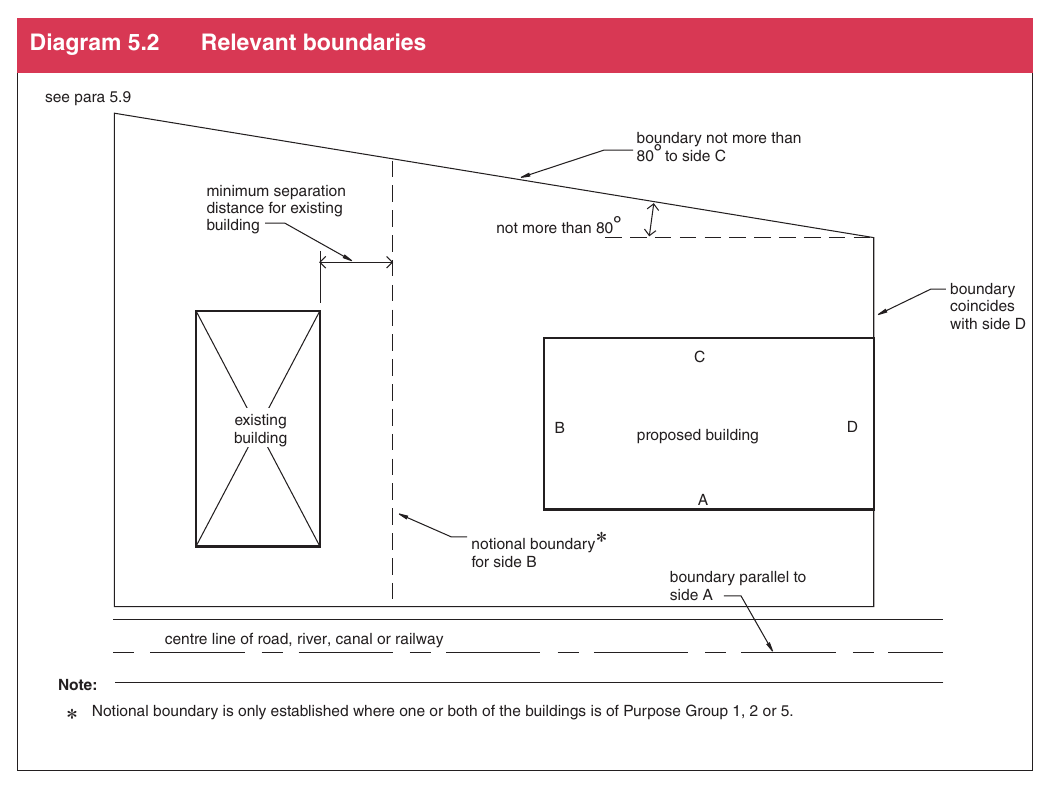
Page 141
#Source page 141
Unprotected areas in external walls
5.10Any part of an external wall which has less fire resistance than that required by Section 4 should be considered to be an unprotected area.
Where an external wall has the appropriate fire resistance but has a combustible material more than 1 mm thick as its external surface, that wall should be considered to be an unprotected area amounting to half the actual area of the combustible material as shown in Diagram 5.3. However, where such a combustible material has a Class 0 (National class) or Class B-s3,d2 or higher (European class) classification it need not be considered to be such an unprotected area.
Any part of the external wall of a protected stairway should be discounted when calculating unprotected areas. (However, Section 2 and Section 6 contain provisions relating to the relationship between the external walls of protected stairways and the unprotected areas of other parts of the building.)
Small unprotected areas may be discounted where they occur in an otherwise protected area of wall, provided that they do not exceed the areas and comply with the minimum spacing shown in Diagram 5.4.
Diagram 5.3 Combustible material on external walls
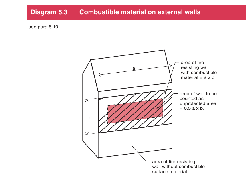
5.11 An external wall situated within 1 m of any point on its relevant boundary should have no unprotected areas other than those shown in Diagram 5.4.
#Source page 142
5.12An external wall situated 1 m or more from any point on its relevant boundary may have unprotected areas provided that their total area does not exceed that given by the most favourable calculation method given in paragraphs 5.13 to 5.19. Where a building is uncompartmented any part of an external wall which is more than 30 m above ground level may be discounted in the calculation.
Diagram 5.4 Unprotected areas which may be discounted
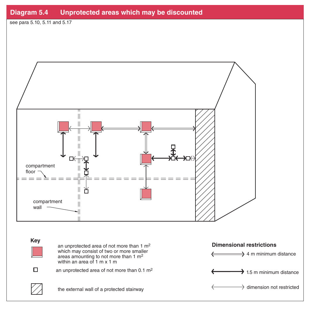
Page 143
#Source page 143
Provisions for and calculation of space separation and unprotected areas
5.13A building should be separated from its relevant boundaries by at least half the distance at which the total thermal radiation intensity received from all unprotected areas in the external walls would be 12.6 kW/m2 (in still air) assuming the radiation intensity at each unprotected area is –
(a)84 kW/m2 where the building is of Purpose Group 1, 2, 3, 5 or 7(b); or
(b)168 kW/m2 where the building is of any other purpose group.
Where a building is compartmented each compartment should be calculated separately.
Where a building or compartment is fitted throughout with a sprinkler system in accordance with Section 8 complying with the relevant provisions of BS 5306-2 or BS EN 12845 for the appropriate occupancy, the thermal radiation intensities in (a) and (b) and the distances calculated using the methods given in paragraphs 5.16 to 5.19 may be halved subject to there being a minimum distance of 1 m. Alternatively, the amount of unprotected area may be doubled if the calculated boundary distance is maintained.
5.14Building Research Establishment Report – External fire spread: building separation and boundary distances (BR 187: 1991) gives the method by which the thermal radiation intensity should be calculated for paragraph
5.13.It also gives detailed explanations, with worked examples, of Method 3 (paragraph 5.18) and Method 4 (paragraph 5.19).
5.15Where a building is compartmented and contains an atrium in accordance with paragraph 4.23(d) the relevant recommendations of BS 9999 BS 5588-
7: Clause 28.2 may be followed for calculation purposes.
Method 1 (Small residential buildings)
5.16This method may only be used for buildings in Purpose Groups 1 and 2(b) which do not exceed three storeys in height and are not more than 24 m in length. The maximum total area of unprotected areas in the side of a building should not exceed that given in Table 5.2 for the relevant minimum distance between that side and its boundary.
| Table 5.2 Unprotected areas in s (Method 1) | mall residential buildings |
|---|---|
| Minimum distance between side of building and relevant boundary (m) | Maximum total area of unprotected areas (m²) |
| 1 | 5.6 |
| 2 | 12 |
| 3 | 18 |
| 4 | 24 |
| 5 | 30 |
| 6 | No limit |
Page 144
#Source page 144
Method 2 (Small buildings and compartments)
5.17This method may be used for buildings and compartments of any purpose group which do not exceed 10 m in height [this height limit does not apply to buildings of Purpose Group 7(b)]. The maximum total percentage of unprotected area in the side of a building should not exceed that given in Table 5.3 for the appropriate purpose group and minimum distance between that side and its relevant boundary. When calculating the unprotected area, any area which complies with paragraph 5.10 and Diagram 5.4 may be discounted.
Table 5.3 Unprotected areas in small buildings and compartments (Method 2)
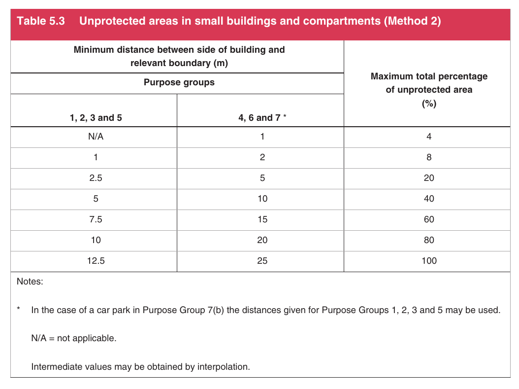
Page 145
#Source page 145
Method 3 (Enclosing rectangle)
5.18This method may be used for buildings and compartments of any purpose group. A building or compartment should be so situated that no point on its relevant boundary is –
(a)between the relevant plane of reference and the side of the building; and
(b)closer to the relevant plane of reference than that given in Table 5.4 for the appropriate purpose group, dimensions of enclosing rectangle and unprotected area percentage.
A plane of reference is a vertical plane which touches the side, or some part of the side, of a building or compartment but which (however, far extended) does not pass within the structure (excluding balconies, copings and similar projections) of that building or compartment. The relevant plane of reference should be chosen to give the least separation distance between it and the relevant boundary. Normally, it is best for the plane of reference to be parallel to the relevant boundary.
The enclosing rectangle is the rectangle, of the least width and height given in Table 5.4, on the relevant plane of reference, which will –
(i)enclose all the outer edges of the unprotected areas in the external wall of the building or compartment (other than any which is at an angle of 80° or more to the plane of reference). The outer edges should be projected to the plane of reference by lines perpendicular to such plane; and
(ii)have two horizontal sides.
The total unprotected area is found by adding the areas, as projected on the plane of reference, of all unprotected areas.
The unprotected percentage is calculated from – unprotected = total unprotected area x 100 percentage enclosing rectangle area
The minimum distance from the plane of reference to the relevant boundary is given in Table 5.4, and where the unprotected percentage is between the values given in the Table the distance may be obtained by linear interpolation.
Page 146
#Source page 146
Table 5.4 Permitted unprotected percentages in relation to enclosing rectangles (Method 3)
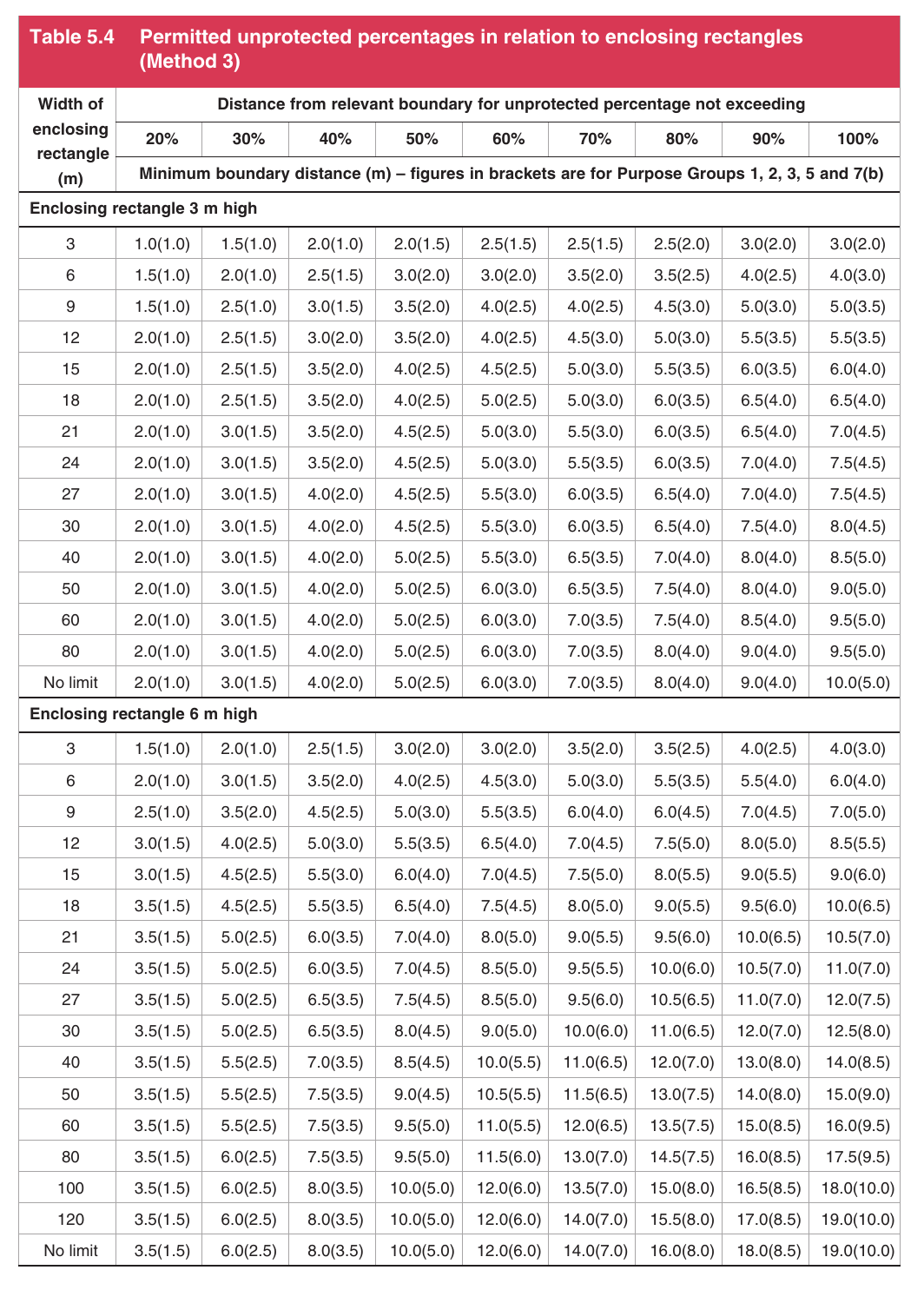
Page 147
#Source page 147
Table 5.4 Permitted unprotected percentages in relation to enclosing rectangles (Method 3) (cont’d)
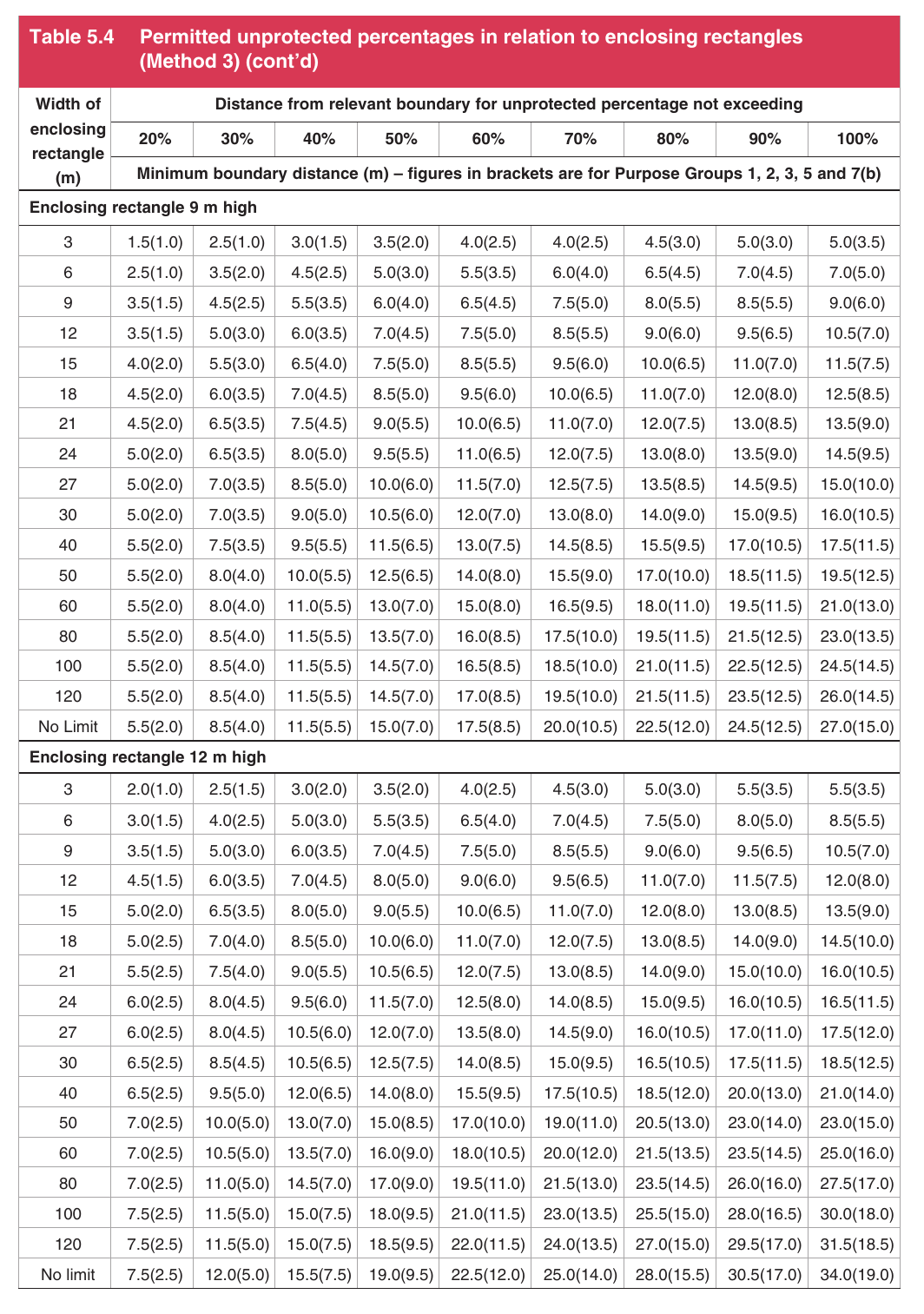
Page 148
#Source page 148
Table 5.4 Permitted unprotected percentages in relation to enclosing rectangles (Method 3) (cont’d)
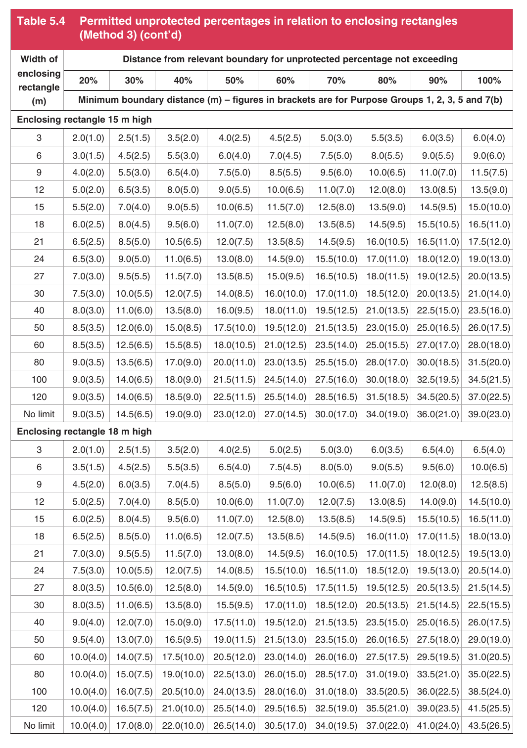
Page 149
#Source page 149
Table 5.4 Permitted unprotected percentages in relation to enclosing rectangles (Method 3) (cont’d)
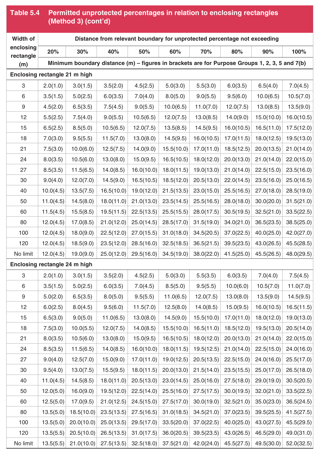
Page 150
#Source page 150
Table 5.4 Permitted unprotected percentages in relation to enclosing rectangles (Method 3) (cont’d)
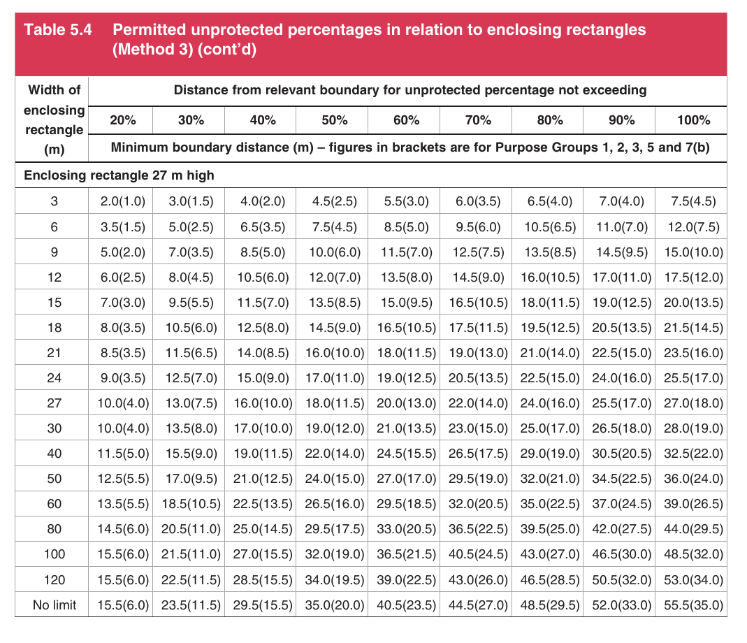
Page 151
#Source page 151
Method 4 (Aggregate notional area)
5.19This method can be used for a building or compartment of any purpose group. A building or compartment should be so situated that the aggregate notional area of the unprotected areas in the side of the building or compartment does not exceed, in the case of –
(a)a building or compartment of Purpose Group 1, 2, 3, 5 or 7(b) – 210 m2; or
(b)a building or compartment of any other purpose group – 90 m2,
when calculated from any vertical datum on its relevant boundary.
The aggregate notional area is the aggregate of the areas of unprotected area in the side of the building or compartment, each such unprotected area being multiplied by the Factor given in Table 5.5 relative to the distance the unprotected area is from the vertical datum.
A vertical datum is a vertical line of unlimited height at any point on the relevant boundary and the datum line is the line joining the vertical datum to the nearest point on the side of the building or compartment.
When calculating the aggregate notional area no account should be taken of any unprotected area which is –
(i)screened from the vertical datum by any part of an external wall which is not an unprotected area;
(ii)outside a horizontal area centred on the vertical datum, having a radius of 50 m and extending 90° on either side of the datum line;
(iii) facing away from the vertical datum; or
(iv) making an angle of less than 10° with a line drawn from it to the vertical datum.
Table 5.5 Multiplication factors for determining aggregate notional areas (Method 4)
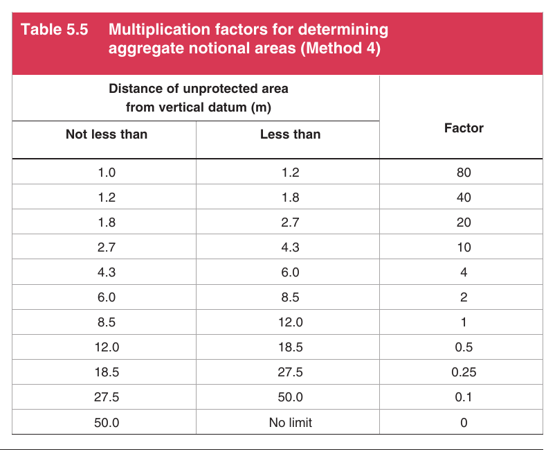
Page 152
#Source page 152
Canopies
5.20The high degree of ventilation and heat dissipation achieved by open sided canopies means that the space separation required by paragraph 5.13 may be onerous.
The provisions of paragraph 5.13 should not apply to –
(a)a free standing single storey, open sided canopy, constructed of non- combustible materials, which is not less than 1 m from its relevant boundaries; and
(b)a covered way, covered yard or a carport, which is open on two or more sides and is not more than 40 m2 in area.
When determining the separation distance an attached single storey canopy which is not less than 2 m from its relevant boundaries and open on all sides other than the attached side may be discounted (see Diagram 5.5).
The provisions regarding roof coverings and roof separation distances should apply (see paragraph 5.21 to 5.26).
Diagram 5.5 The effect of an attached canopy on separation distance
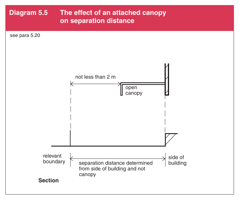
Page 153
#Source page 153
Roofs
Roof covering designations (National tests)
5.21The designation of a roof covering in respect of external fire exposure should be determined by testing in accordance with BS 476: Part 3 and expressed by two letters in the range A to D with an AA classification being the best. The first letter indicates the time to penetration and the second letter indicates a measure of the spread of flame. The notional designations of some generic roof coverings are given in Table 5.6.
Note – The National classifications do not automatically equate with the equivalent European classifications, therefore products cannot typically assume a European class unless they have been tested accordingly.
Roof covering designations (European tests)
5.22Performance in terms of the resistance of roofs to external fire exposure is determined by reference to Commission Decision 2005/823/EC amending Decision 2001/671/EC establishing a classification system for the external fire performance of roofs and roof coverings.
Constructions are classified within the European system as BROOF(t4), CROOF(t4), DROOF(t4), EROOF(t4) or FROOF(t4) in accordance with BS EN 13501-5: Fire classification of construction products and building elements: Classification using data from external fire exposure to roof tests. With BROOF(t4) being the highest performance and FROOF(t4) being the lowest.
BS EN 13501-5 refers to four separate tests. The suffix (t4) used above indicates that test4 is to be used for the purposes of this Technical Booklet.
5.23Where a thermoplastic material cannot be given a designation when tested to BS 476: Part 3 it may be used as a rooflight provided that it can be classified under paragraph 3.5 and is used in accordance with paragraph
5.25.Where unwired glass, not less than 4 mm thick, is used in a rooflight it should be regarded as having an AA (National class) or BROOF(t4) (European class) designation.
Page 154
#Source page 154
Table 5.6 Notional designations of roof coverings
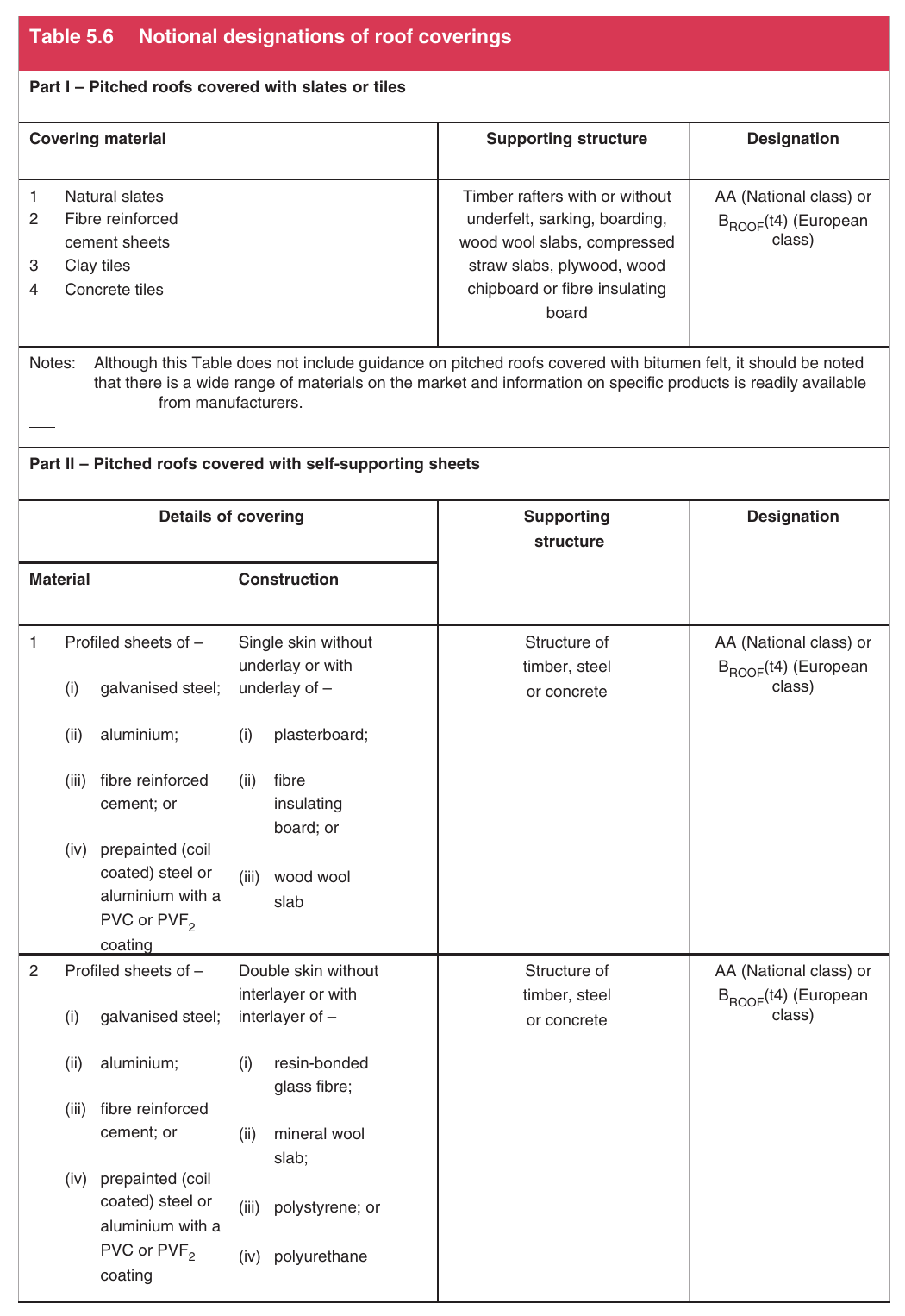
Page 155
#Source page 155
Table 5.6 Notional designations of roof coverings (contd)
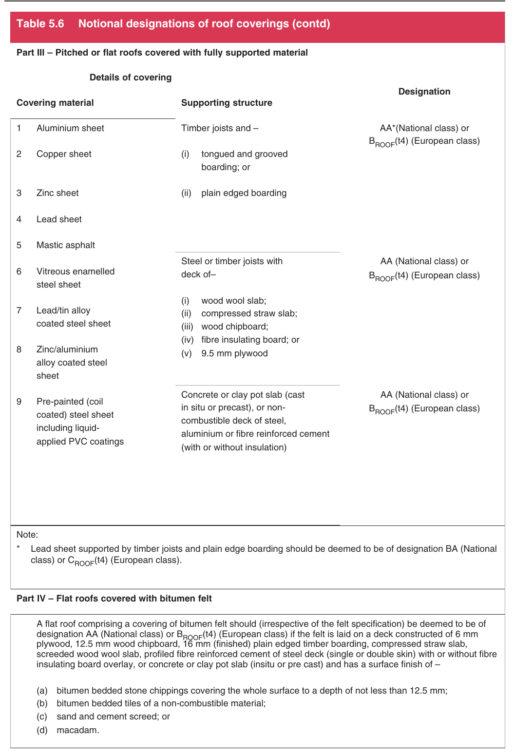
1Aluminium sheet
2Copper sheet
3Zinc sheet
4Lead sheet
5Mastic asphalt
| Timber joists and – (i) tongued and grooved boarding; or | AA*(National class) or B (t4) (European class) ROOF |
|---|---|
| (ii) | plain edged boarding |
6Vitreous enamelled steel sheet
7Lead/tin alloy coated steel sheet
8Zinc/aluminium alloy coated steel sheet
| Steel or timber joists with deck of– | AA (National class) or B (t4) (European class) ROOF |
|---|---|
| (i) (ii) (iii) (iv) (v) | wood wool slab; compressed straw slab; wood chipboard; fibre insulating board; or 9.5 mm plywood |
| Concrete or clay pot slab (cast | AA (National class) or |
| in situ or precast), or non- | B (t4) (European class) ROOF |
| combustible deck of steel, | |
| aluminium or fibre reinforced cement | |
| (with or without insulation) |
* Lead sheet supported by timber joists and plain edge boarding should be deemed to be of designation BA (National class) or CROOF(t4) (European class).
A flat roof comprising a covering of bitumen felt should (irrespective of the felt specification) be deemed to be of designation AA (National class) or BROOF(t4) (European class) if the felt is laid on a deck constructed of 6 mm plywood, 12.5 mm wood chipboard, 16 mm (finished) plain edged timber boarding, compressed straw slab, screeded wood wool slab, profiled fibre reinforced cement of steel deck (single or double skin) with or without fibre insulating board overlay, or concrete or clay pot slab (insitu or pre cast) and has a surface finish of –
(a)bitumen bedded stone chippings covering the whole surface to a depth of not less than 12.5 mm;
(b)bitumen bedded tiles of a non-combustible material;
(c)sand and cement screed; or
(d)macadam.
Page 156
#Source page 156
Space separation - roofs
5.24The minimum distance from any part of a roof, other than a plastic rooflight, to a relevant boundary (see paragraph 5.9) should be not less than that given in Table 5.7 for the relevant designation of roof covering. There are no restrictions on the use of roof coverings designated AA, AB or AC (National class) or BROOF(t4) (European class). In addition, roof covering products (and/or materials) as defined in Commission Decision 2000/553/EC implementing Council Directive 89/106/EEC as regards the external fire performance of roof coverings can be considered to fulfil all of the requirements for performance characteristic “external fire performance” without the need for testing provided that any national provisions on the design and execution of works are fulfilled. That is, the roof covering products (and/or materials) defined in this Commission Decision can be used without restriction.
The boundary formed by the compartment wall separating semi-detached dwellinghouses should be disregarded for the purposes of this paragraph.
Table 5.7 Limitations on roof coverings
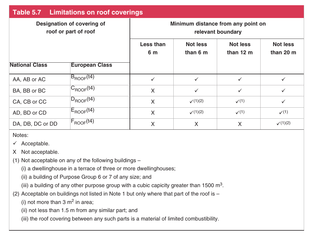
Page 157
#Source page 157
5.25Where a roof incorporates a plastic rooflight, which is not designated AA, AB, AC, BA, BB or BC (National class), or BROOF(t4) or CROOF(t4) (European class), the minimum distance from that rooflight to a relevant boundary should be not less than that given in Tables 5.8 and 5.9 for the appropriate classification of the rooflight and the space over which it is located.
For the purposes of this paragraph and Tables 5.8 and 5.9 a rigid thermoplastic rooflight, made from polycarbonate or unplasticised PVC, which achieves a Class 1 classification for surface spread of flame (see paragraph 3.4) may be regarded as having an AA (National class) or BROOF(t4) (European class) designation (other than for the purposes of paragraph 4.21(a) and Diagram 4.2).
5.26Thatch or wood shingles should be regarded as having an AD, BD or CD (National class) or EROOF(t4) (European class) designation in Table 5.7 where performance under BS 476: Part 3 or ENV 1187, test4 cannot be established.
Table 5.8 Plastic rooflights – Limitations on use and boundary distance
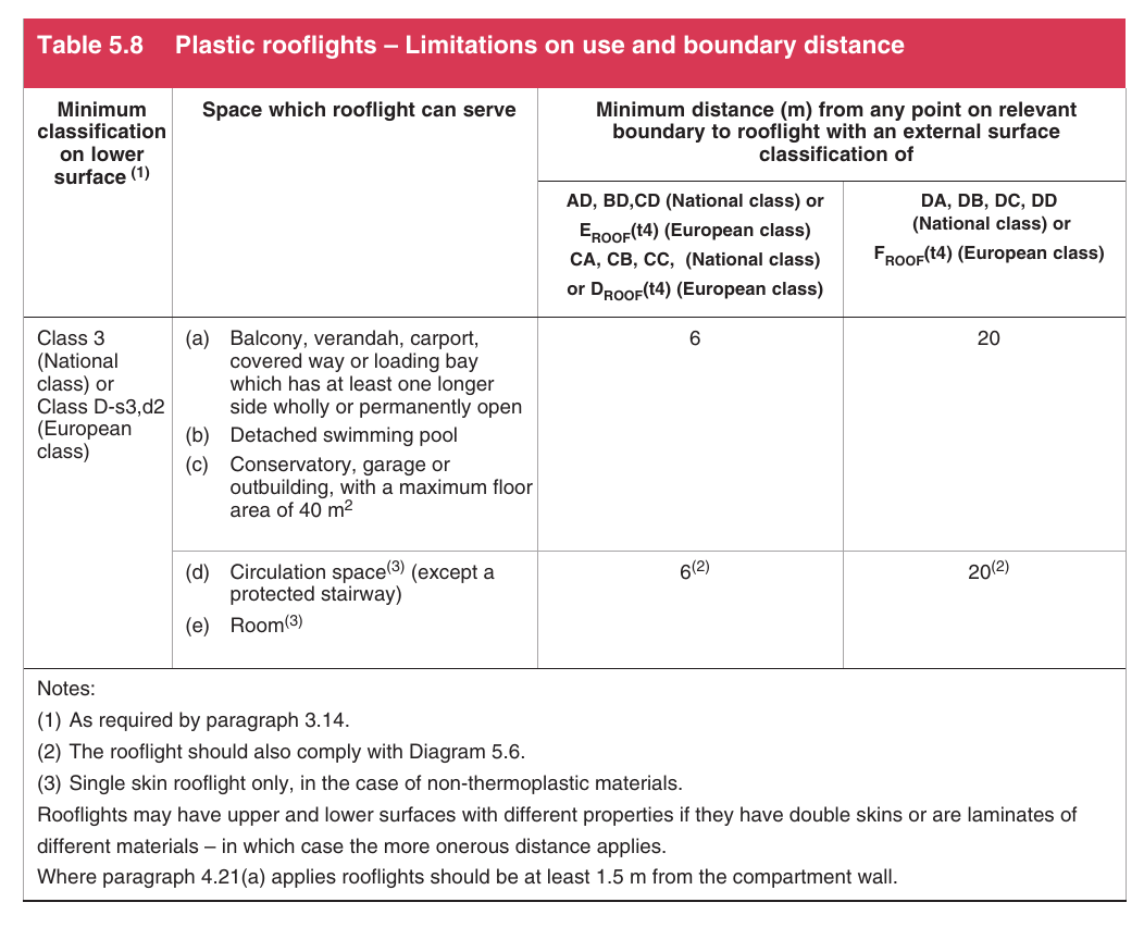
Page 158
#Source page 158
Table 5.9 TP(a) and TP(b) plastic rooflights – Limitations on use and boundary distance
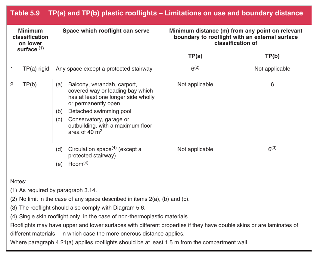
Page 159
#Source page 159
Diagram 5.6 Limitation on areas and spacing of certain thermoplastic rooflights
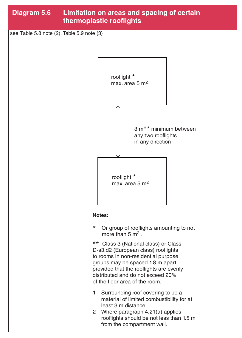
Page 160
#Source page 160
Section 6 Facilities and access for the Fire and Rescue Service
6.1This Section contains provisions to ensure that there is –
(a)sufficient means of access to and within a building for firefighting personnel to effect rescue and fight fire;
(b)sufficient facilities to assist firefighters in their tasks;
(c)adequate means of venting smoke from a fire in a basement; and
(d)adequate external access to enable firefighting appliances to be brought near to a building for effective use.
6.1A The main factor determining the facilities needed to assist the Fire and Rescue Service is the size of the building. Generally, most firefighting is carried out within the building.
6.1B If it is proposed to deviate from the guidance in Section 6, then it would be advisable to seek advice from the Fire and Rescue Service at the earliest opportunity.
Firefighting shafts
6.2In low rise buildings without deep basements fire and rescue personnel access requirements will be met by a combination of the normal means of escape in the building and the measures for vehicle access in accordance with paragraphs 6.19 and 6.20. In other buildings including high rise buildings and those with deep basements the problems of reaching the fire and working inside the building near the fire, necessitate the provision of additional facilities to avoid delay and to provide a sufficiently secure operating base to allow effective action to be taken. These additional facilities include firefighting lifts, firefighting stairs and firefighting lobbies which are combined in a protected shaft known as a firefighting shaft. (See Diagram 6.0)
6.3A shopping complex should be provided with firefighting shafts in accordance with the recommendations of BS 5588-10 Section 3. Any other A building should be provided with a firefighting shaft or shafts, to serve all storeys, where –
(a)it has a storey more than 18 m above fire and rescue access level;
(b)it is a building of Purpose Group 4, 5, 6 or 7(a) and has a storey 900 m2 or more in area at a height of 7.5 m or more above fire and rescue access level;
(c)it has a storey more than 10 m below fire and rescue access level; or
(d)it has two or more basement storeys any of which is 900 m2 or more in area.; or
(e)it is a shopping complex, in accordance with the relevant recommendations of BS 9999.
Page 161
#Source page 161
However, a firefighting shaft provided under (a) or (b) need not serve a basement storey unless (c) or (d) applies and similarly a firefighting shaft provided under (c) or (d) need not serve an upper storey unless (a) or (b) applies.
Diagram 6.1 illustrates the provisions of this paragraph.
Diagram 6.0 New Components of a firefighting shaft
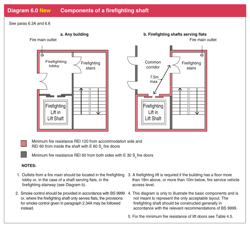
Page 162
#Source page 162
Diagram 6.1 Provision of firefighting shafts
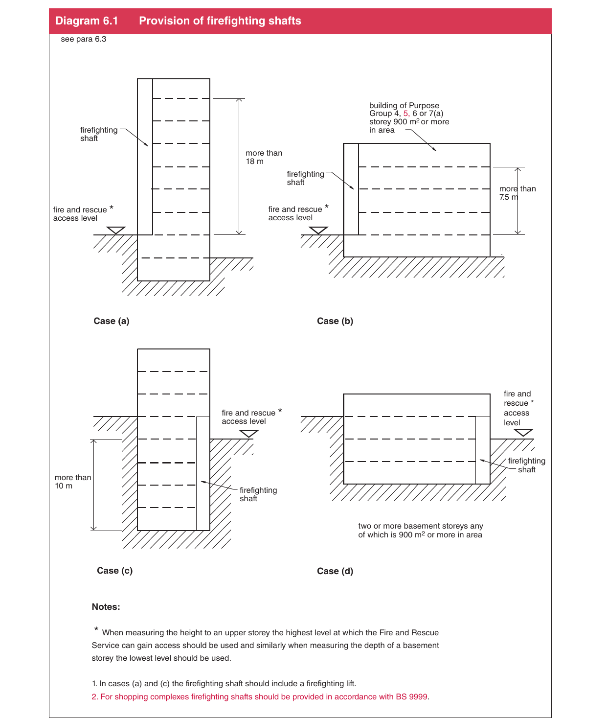
Page 163
#Source page 163
6.3A A minimum of two firefighting shafts (each containing a firefighting lift) should be provided to buildings with a storey that has a floor area of 900 m2 or more and a floor level 18 m or more above fire and rescue service access level.
6.3B A minimum of two firefighting shafts (which do not need to include a firefighting lift) should be provided to buildings where 6.3(b) applies.
Location of firefighting shafts
6.3C Firefighting shafts and protected stairways should be located such that –
(a)If the building is fitted throughout with a sprinkler system in accordance with Section 8, then sufficient fire-fighting shafts should be provided so that every part of every storey is no more than 60 m from a fire main outlet in a firefighting shaft (see Diagram 6.1B a and b).
(b)If the building is not fitted with sprinklers, then every part of every storey should be no more than 60 m from a fire main in a fire-fighting shaft and in addition 45 m from a fire main outlet in a protected stairway (see Diagram 6.1B c, d and e).
Note 1: Distance should be measured from the fire main outlet on a route suitable for laying a hose.
Note 2: If the internal layout is not known, direct distances may be used for assessment. The direct distance is taken as two thirds of the travel hose laying distance.
Note 3: In order to meet the 45 m hose criterion in (b), it might be necessary to provide additional fire mains in protected stairways. This does not imply that these stairways need to be designed as fire-fighting shafts.
6.4Where a building is to be provided with firefighting shafts the minimum number (subject to paragraph 6.5) should be –
(a)where a building is fitted throughout with an automatic sprinkler system complying with the relevant recommendations of BS 5306-2 or BS EN 12845 as given in Table 6.1 for the appropriate floor area; or
(b)where a building is not fitted throughout with such a sprinkler system
– at least one for every 900 m2, (or part thereof) of floor area of the largest storey given in paragraph 6.3(a) to (d) as appropriate.
6.5Firefighting shafts should be located so that every part of every storey (other than fire and rescue access level) is not more than 60 m from a fire main outlet, measured on a route suitable for laying a fire hose (hose route). Where the internal layout is unknown every part of every such storey should be not more than 40 m, in a direct line, from a fire main outlet.
Page 164
#Source page 164
Diagram 6.1B Location of firefighting shafts: hose laying distances
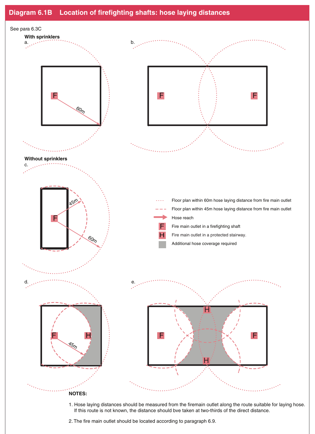
Page 165
#Source page 165
| Table 6.1 | Minimum number of firefighting shafts in a building fitted with a sprinkler system |
|---|---|
| Floor area of the largest storey (m²) | Minimum number of firefighting shafts |
| Less than 900 | 1 |
| 900 to 2000 | 2 |
| Over 2000 | 2 plus 1 for every 1500 m² or part thereof of floor area |
Design and construction of firefighting shafts
6.6Firefighting shafts should be designed and constructed in accordance with the relevant recommendations of BS 5588-5 BS 9999.
Where a building falls within paragraph 6.3(a) or (c) all firefighting shafts should have a firefighting lift complying with the relevant recommendations of BS 5588-5 BS 9999. A firefighting lift installation includes the lift car itself, the lift well and the lift machinery space, together with the lift control system and the lift communication system. The firefighting lift installation should conform with BS EN 81-1 or BS EN 81-2 BS EN 81-72 and BS EN 81-20. as appropriate for the particular type of lift and BS EN 81-72 .
Every firefighting stair and firefighting lift in a firefighting shaft should be approached from the accommodation area through the firefighting lobby.
However, in a Purpose Group 1(a) (flat) building it is not necessary for a firefighting shaft to have firefighting lobbies provided that –
(a)the firefighting stair opens directly into a protected lobby or protected corridor provided for means of escape; and
(b)where the firefighting shaft has a firefighting lift – the lift opens directly into a protected lobby or protected corridor provided for means of escape and the lift landing doors are not more than 7.5 m from the door to the firefighting stair.
Fire mains
6.7Fire mains are installed in a building and equipped with valves, etc., so that the Fire and Rescue Service may connect hoses for water to fight fires inside the building. Rising fire mains serve floors above ground, or upwards from the level at which the Fire and Rescue Service gain access (called the fire and rescue access level) if this is not ground level. Falling mains serve levels below fire and rescue access level.
Page 166
#Source page 166
Fire mains may be of the dry type which are normally empty and are supplied through hose from a fire and rescue pumping appliance. Alternatively, they may be of the wet type where they are kept full of water and supplied from tanks and pumps in the building. There should be a facility to allow a wet system to be replenished from a pumping appliance in an emergency.
6.8A firefighting shaft should be provided with –
(a)a wet fire main where it has a storey more than 60 50 m above fire and rescue access level; or
(b)a wet or a dry fire main in any other case.
6.9The fire main should be located in the firefighting lobbies of the firefighting shaft and should have an outlet connection and valve at every level other than at fire and rescue access level. However, where firefighting lobbies are not provided in a Purpose Group 1(a) building the fire main should be located in the firefighting stairway.
6.10The design and construction of a fire main should be in accordance with the relevant recommendations of BS 9990.
Provisions for vehicle access are given in paragraph 6.19.
Venting of heat and smoke from basements
6.11The build-up of smoke and heat as a result of a fire can seriously inhibit the ability of the Fire and Rescue Service to carry out rescue and firefighting operations in a basement. The problem can be reduced by providing venting facilities to make conditions tenable by providing a route for smoke and heat to escape to the open air from the basement level. These facilities can also be used by the Fire and Rescue Service to let cooler air into the basement.
6.12Venting facilities, connected directly to the external air, should be provided from every basement storey other than –
(a)a basement in a building of Purpose Group 1(b) or (c);
(b)a basement storey which –
(i)has a floor area not more than 200 m2; or
(ii)has a floor not more than 3 m below the lowest adjacent ground level;
(c)a basement storey used for car parking and ventilated in accordance with paragraph 4.50; and
(d)a basement storey or that part of a basement storey used as a strong room.
Page 167
#Source page 167
6.13Where basements have external doors or windows, the compartments containing the rooms with these doors or windows do not need smoke outlets. It is common for basements to be open to the air on one or more elevations. This may be the result of different ground levels on different sides of the building.
Natural venting
6.14A basement storey may be ventilated by smoke outlets which should –
(a)be sited at ceiling level within the space they serve;
(b)have an aggregate free area of not less than 2.5% of the floor area of the space they serve;
(c)be distributed as evenly as possible around the perimeter of the building;
(d)be located so that they do not adversely affect any escape route from the building; and
(e)have a sign stating “smoke outlet from basement” fixed adjacent to each external outlet point.
The smoke outlets from a place of special fire hazard should be separate from the smoke outlets from other areas.
6.15Smoke outlets may discharge by means of windows, stall-board risers or pavement lights which can be opened or knocked out provided such covers are readily accessible to the Fire and Rescue Service.
Shafts enclosing smoke outlets should be of smoke tight non-combustible construction and have the same period of fire resistance as that for elements of structure in the basement storey served.
Shafts from different parts of the same basement storey, or from different basement storeys, should be separated by smoke tight non-combustible fire-resisting construction.
Mechanical venting
6.16A basement may be ventilated by a mechanical air extraction system provided –
(a)the basement has a sprinkler system fitted in accordance with Section 8 complying with the relevant recommendations of Section 8 BS 5306-2 or BS EN 12845; and
(b)the air extraction system has a capacity of not less than 10 air changes per hour and is capable of operating at a temperature of 300°C for not less than 60 minutes.
Page 168
#Source page 168
The air extraction system should come into operation automatically on the activation of either –
(i)the sprinkler system; or
(ii)the fire detection and fire alarm system in the basement where this system complies with BS 5839-1, of at least Category L3 standard.
Rolling shutters in compartment walls
6.17A rolling shutter in a compartment wall should be provided with a suitable operating mechanism so that it can be opened and closed manually by the Fire and Rescue Service.
Vehicle access
6.18For the purposes of this Section vehicle access to the exterior of a building is needed to enable high reach appliances, such as turntable ladders and hydraulic platforms to be used, and to enable pumping appliances to supply water and equipment for firefighting and rescue purposes.
6.19The provisions for vehicle access are related to whether or not the building has a fire main or mains and, where it does not, to the size and height of the building. Where a building –
(a)does not have a fire main and is a block of flats, access for a pump appliance should be provided to within 45 m (hose route) of each door giving access to all points within each individual dwelling;
(b)does not have a fire main, is not a block of flats and is less than 2000 m2 in area and the height to the top storey is less than 11 m, access for a pump appliance should be –
(i)provided to within 45 m (hose route) of the building other than for a dwellinghouse where the 45 m should be to a door giving access to the interior all points within each individual dwelling; or
(ii)provided to 15% of the perimeter;
(c)does not have a fire main and is other than as described in (a) and (b), access should be provided in accordance with Table 6.2;
(d)has dry fire mains, access for a pumping appliance should be provided to within 18 m, and within sight of, each fire main inlet connection point; and
(e)has wet fire mains, access for a pumping appliance should be provided to within 18 m, and within sight of the emergency replenishment inlet of the tank serving each fire main.
In every elevation to which fire and rescue access is provided, there should be a door not less than 750 mm wide, giving access to the interior of the building. Where fire mains are provided a door should give access to each fire main.
[Note – the Building Regulations cannot impose requirements for work to be done beyond the boundary of the premises.]
Page 169
#Source page 169
Vehicle access routes and vehicular hardstandings areas
6.20A vehicle access route and vehicular hardstanding area should be designed and constructed to the standards given in Table 6.3 and, in the case of those for high reach appliances, the dimensions shown in Diagram 6.2.
Table 6.2 Fire and rescue vehicle access to buildings not fitted with fire mains
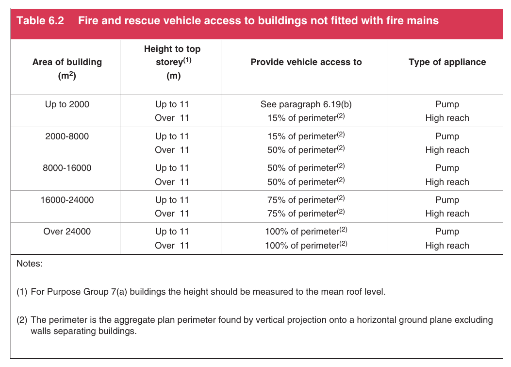
Table 6.3 Fire and rescue vehicle access routes
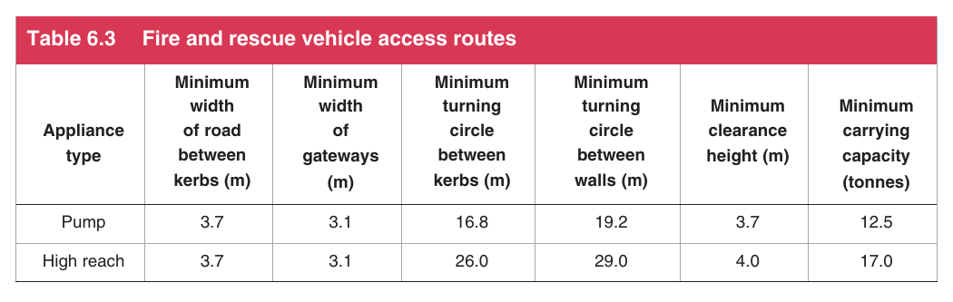
Page 170
#Source page 170
Diagram 6.2 Relationship between a building and a vehicle access route or a vehicular hardstanding area for a high reach appliance
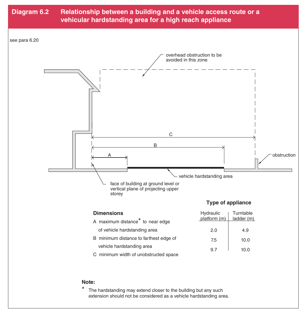
Page 171
#Source page 171
Where the height of the top storey of a building is more than 11 m above the level of the adjoining ground the vehicle access route and the vehicular hardstanding area should be suitable for a high reach appliance. For lower buildings a vehicle access route should be suitable for a pump appliance.
6.21A turning facility should be provided in a dead end vehicle access route which is more than 20 m in length. This should be a hammerhead or turning circle –
(a)designed on the basis of the dimensions given in Table 6.3; and
(b)located so that vehicles do not have to reverse more than 20 m.
Vehicular hardstanding areas should be as level as possible and should not exceed a gradient of 1 in 12.
Evacuation alert systems
6.21A In a building containing flats with a top storey more than 11 m above ground level, an evacuation alert system (EAS) should be provided in accordance with BS 8629.
6.21B The system should enable the fire and rescue service to initiate operation of evacuation alert sounders within each individual dwelling on any single floor, multiple floors and the entire building, according to circumstances.
6.21C An evacuation alert system is not, and should not be confused with, a fire alarm system. The EAS should not be integrated with a fire detection and fire alarm system (or any other system), nor should any devices (such as fire detectors), other than evacuation alert devices, be connected to the EAS.
Wayfinding signage
6.21D To assist the fire and rescue service to identify each floor in a building containing flats with a top storey more than 11 m above ground level, floor identification signs and flat indicator signs should be provided.
6.21E The floor identification signs should meet all of the following—
(a)the signs should be located on every landing of a protected stairway and every protected corridor/lobby (or open access balcony) into which a firefighting lift opens;
(b)the text should be in sans serif typeface with a letter height of at least 50 mm. The height of the numeral that designates the floor number should be at least 75 mm;
(c)the signs should be visible from the top step of a firefighting stair and, where possible, from inside a firefighting lift when the lift car doors open;
(d)the signs should be mounted between 1.7 m and 2 m above floor level and, as far as practicable, all the signs should be mounted at the same height;
(e)the text should be on a contrasting background, easily legible and readable in low level lighting conditions or when illuminated with a torch;
Page 172
#Source page 172
(f)the wording used on each floor identification sign should take the form Floor X, with X designating the number of the storey, as intended for reference by residents.
6.21F The floor number designations should meet all of the following conditions—
(a)The floor closest to the mean ground level should be designated as either Floor 0 or Ground Floor;
(b)Each floor above the ground floor should be numbered sequentially beginning with Floor 1;
(c)A lower ground floor should be designated as either Floor -1 or Lower Ground Floor;
(d)Each floor below the ground floor should be numbered sequentially beginning with Floor -1 or Basement 1.
6.21G All floor identification signs should be supplemented by flat indicator signs, which provide information relating to the flats accessed on each storey. The flat indicator signs should meet all of the following—
(a)The signs should be sited immediately below the floor identification signs, such that the top edge of the sign is no more than 50 mm below the bottom edge of the floor identification sign;
(b)The wording should take the form Flats X-Y, with the lowest flat number first;
(c)The text should be in sans serif typeface with a letter height of at least half that of the floor indicator sign;
(d)The wording should be supplemented by arrows when flats are in more than one direction;
(e)The text and arrows should be on a contrasting background, easily legible and readable in low level lighting conditions or when illuminated with a torch.
Note: In the case of multi-storey flats with two or more entrances, the flat number should only be indicated on the normal access storey
Secure Information Boxes
6.21H A secure information box provides a secure facility to store information about a building for use by the fire and rescue service during an incident.
6.21J A building containing flats with a top storey more than 11 m above ground level should be provided with a secure information box.
Note – Consideration should also be given to other buildings with large, complex or uncommon layouts where the provision of a secure information box may be beneficial.
6.21K The box should meet all of the following conditions—
(a)sized to accommodate all necessary information;
(b)easily located and identified by firefighters
(c)secured to resist unauthorised access but readily accessible by firefighters; and
(d)protected from the weather.
Page 173
#Source page 173
6.21L Best practice guidance can be found in Sections 2 to 4 of the ‘Code of Practice for the Provision of Premises Information Boxes in Residential Buildings’ published by the Fire Industry Association (FIA).
Note: This FIA publication also sets out the information the fire and rescue service would expect to see stored within a secure information box.
Page 174
#Source page 174
Section 7 Fire safety information
Introduction
7.1Regulation 37A requires that the person carrying out the work must provide sufficient fire safety information for persons to operate and maintain the building in reasonable safety. This information should be given at the completion of the work or when the building is first occupied (whichever is earlier).
Note 1 - A building should not be occupied prior to all relevant fire safety measures in the building are completed.
Note 2 - In buildings containing one or more flats, the person with fire safety duties will ordinarily be the landlord, the freeholder or management agent for the building.
7.2For existing buildings which are relevant premises or buildings containing one or more flats, subject to extension and/or alteration work, the information required should only relate to the work involved where it has an impact on the fire safety strategy of the building.
7.3The “Details of information” in this section is not a check list but is intended as a guide to the kind of information that should be provided. Each design should be considered on a case by case basis to establish the level of detail required.
Details of information
7.4For most buildings, basic information on the location of fire protection measures may be sufficient. An as-built plan of the building should be provided showing —
a)escape routes – this should include exit capacity (i.e. the maximum allowable number of people for each storey and for the building);
b)fire-resisting construction and location of fire-separating elements (including cavity barriers in walk-in spaces);
c)fire doorsets, fire doorsets fitted with a self-closing device and other doors equipped with relevant hardware;
d)locations of fire and/or smoke detector heads, alarm call-points, detection/alarm control boxes, alarm sounders, fire safety signage, emergency lighting, fire extinguishers, dry or wet fire mains and other firefighting equipment and hydrants outside the building;
e)any sprinkler system provided (whether as a compensatory feature or otherwise), including isolating valves and control equipment;
f)any smoke control system(s) or ventilation system with a smoke control function, including mode of operation and control systems; and
g)any high risk areas (e.g. heating machinery);
h)any power supplies or power generating installations;
i)the location of secure information boxes.
Page 175
#Source page 175
7.5Details should be provided of all of the following –
a)specifications of any fire safety equipment provided, including routine maintenance schedules;
b)any assumptions regarding the management of the building in the design of the fire safety arrangements; and
c)any provision enabling the evacuation of disabled people, which can be used when designing suitable personal emergency evacuation plans.
7.6For more complex buildings, a detailed record should be provided for both the fire safety strategy and the procedures for operating and maintaining any fire protection measures. This should include an outline cause and effect matrix/strategy for the building.
Further guidance is available in the relevant recommendations of BS 9999.
The records should include details of all of the following –
a)the fire safety strategy, including all assumptions in the design of the fire safety systems (such as fire load). Any risk assessments or risk analysis;
b)all assumptions in the design of the fire safety arrangements for the management of the building;
c)all of the following -
i.escape routes (including occupant load and capacity of escape routes);
ii.any provision to enable the evacuation of disabled people;
iii.escape strategy (e.g. simultaneous or phased) and
iv.assembly and muster points.
d)all passive fire safety measures, including all of the following -
i.compartmentation;
ii.fire-separating elements;
iii.fire-separating construction;
iv.cavity barriers;
v.fire doorsets, including fire doorsets fitted with a self-closing device and other doors relevant to the fire safety strategy, such as doors equipped with relevant hardware (e.g. electronic security locks
vi.fire dampers, fire and smoke dampers and smoke control dampers; and
vii.fire shutters.
e)all of the following -
i.fire detector heads;
ii.smoke detector heads;
iii.alarm call points;
iv.detection/alarm control boxes;
v.alarm sounders;
vi.emergency communications systems;
Page 176
#Source page 176
vii.cctv;
viii.fire safety signage;
ix.emergency lighting;
x.fire extinguishers;
xi.dry or wet fire mains and other firefighting equipment;
xii.other interior facilities for the fire and rescue service;
xiii.emergency control rooms;
xiv.location of hydrants outside the building;
xv.other exterior facilities for the fire and rescue service;
xvi.any evacuation alert sounder system; and xvii.location of secure information boxes.
f)all active fire safety measures, including both of the following
g)any high risk areas (e.g. heating machinery) and particular hazards;
h)plans of the building as built, showing the locations of the above;
i)both of the following -
| i. | Sprinkler system(s) design (whether as a compensatory feature or otherwise), including isolating valves and control equipment; and |
| ii. | Smoke control system(s) (or heating, ventilation and air conditioning system with a smoke control function) design, including mode of operation and control systems. |
i. specifications of any fire safety equipment provided, including all of the following -
• operational details •operators manual
•software
•system zoning
•routine inspection, testing and maintenance schedules
ii. records of any acceptance or commissioning tests j) any other details appropriate for the specific building.
Sprinklers
#Source page 177
Section 8 Automatic Fire Suppression Systems
Sprinklers
8.1For the purpose of guidance to satisfy Regulation 37B, sprinklers are the only suitable form of automatic fire suppression system referenced in this Technical Booklet.
8.2Sprinkler systems installed in buildings can reduce the risk to life and significantly reduce the degree of damage caused by fire within a building.
8.3This Technical Booklet requires automatic sprinkler provision –
(a)where phased evacuation is employed in a building with a storey more than 30 m above ground level (see paragraph 2.66);
(b)in certain buildings with a top storey over 30 m above ground level (see Table 4.2); and
(c)in certain buildings as listed in paragraph 8.5.
8.4This Technical Booklet gives further recommendations for the provision of sprinklers as a compensatory feature in relation to –
(a)shop store-rooms (see paragraph 2.103);
(b)raised storage floors (see paragraph 4.14);
(c)maximum floor areas and volumes of buildings or compartments (see Table 4.4);
(d)provisions for and calculation of space separation and unprotected areas (see paragraph 5.13);
(e)location of firefighting shafts (see paragraph 6.3C); and
(f)mechanical venting of basements (see paragraph 6.16).
Regulation 37B
8.5To satisfy the requirements of Regulation 37B, an automatic sprinkler system should be provided in –
(a)a building, containing one or more flats, with a storey more than 11 m above ground level;
(b)a purpose built student accommodation building with a storey more than 11 m above ground level; and
(c)residential care premises.
8.6Regulation 37B applies when any of the above buildings in paragraph 8.5 are newly erected or formed after a material change of use. It also applies to certain alterations and/or extensions where Regulation 37B has been applied.
8.7Where an existing building is already provided with an automatic sprinkler system, the building as a whole should be no less compliant after an alteration and/or extension. The automatic sprinkler system should be extended and recertified to include any altered, extended and additional controlled areas.
Page 178
#Source page 178
8.8Where an existing building is not curently provided with an automatic sprinkler system and an alteration and/or extension is undertaken, then the introduction of a sprinkler system to the new or existing areas of the building is not required.
Design of sprinkler systems
8.9Where required, sprinkler systems should be provided throughout the building (or part of the building) or separated part, unless acting as a compensatory feature to address a specific risk.
8.10Automatic sprinkler systems should be designed and installed in accordance with the following –
(a)For residential buildings, the requirements of BS 9251; and
(b)For non-residential buildings, or residential buildings outside the scope of BS 9251, the requirements of BS EN 12845 including the relevant hazard classification together with additional measures to improve system reliability and availability as described in the relevant recommendations of the standard.
Note 1: Any sprinkler system installed to satisfy the requirements of Part E of the Building Regulations should be provided with additional measures to improve system reliability and availability and is therefore to be regarded as a life safety system. However, there may be some circumstances in which additional measures to improve system reliability and availability specified in the relevant recommendations of BS EN 12845 are inappropriate or unnecessary.
Note 2: BS 9251 makes additional recommendations when sprinklers are proposed as compensatory features.
Water supplies and pumps
8.11For non-residential sprinkler systems designed and installed to BS EN 12845, water supplies and pumps should be in accordance with the relevant recommendations of that standard.
8.12For a sprinkler system to be effective it is essential that there is an appropriate water supply. It is recognised that pressures will vary during the day and night and over the year. Therefore, it is imperative that the system is designed on the basis of what minimum pressure and flow is likely to be. If there is any doubt, a tank and pump arrangement should be used.
8.13It is strongly recommended that developers and designers should discuss project specific details with Northern Ireland Water and the suppression system provider early in the design process, to determine what supply is likely to be available and what pressure can be expected.
Other automatic fire suppression systems
#Source page 179
8.14There are many other and innovative automatic fire suppression systems available. Where these are proposed, it is necessary to ensure such systems have been designed, performance tested and approved for use in buildings and are fit for their intended purpose.
8.15Where another system other than sprinklers is proposed, designers should demonstrate any such system gives an equivalent or better level of performance to that of an automatic sprinkler system.
Page 180
#Source page 180
Appendix A Purpose Groups
A.1 The provisions of this Section should apply when using Sections 2 to 6 8 of this Technical Booklet.
Purpose groups
A.2 As many of the provisions in this Technical Booklet are related to the use of a building or compartment it is necessary to classify each building and compartment, according to its use, into a purpose group.
A building may have a single use or it may have many uses. Sub-paragraphs (b) and (c) describe the circumstances where it is appropriate to treat a different use as a purpose group in its own right. (Note that the provisions of paragraph 4.17 require compartmentation between different purpose groups.)
Every building and compartment should be classified according to its use, or intended use, into the most appropriate of those purpose groups given in Table A.1 and –
(a)where the use of a building or compartment will vary from time to time, it should be classified as the purpose group to which the more or most onerous provisions in Section 4 apply;
(b)where a building or compartment has one or more uses which are not ancillary to the main use of that building or compartment, each portion given over to a separate use should be classified separately; and
(c)where the building or compartment has one or more uses which are ancillary to the main use of that building or compartment, each portion given over to an ancillary use should be classified separately when –
(i)it is a flat;
(ii)in a Purpose Group 4 building or compartment more than 280 m2 in floor area – it is storage occupying more than one third of the total floor area of the building or compartment; or
(iii) in a building or compartment of any purpose group more than 280 m2 in floor area – it is a use [other than in (i) and (ii)] occupying more than one fifth of the total floor area of the building or compartment.
Page 181
#Source page 181
Table A.1 Classification of purpose groups
Title
Residential*+ (Dwellings)
Residential (Institutional)
(Other)
Office
Shop and Commercial
Assembly and Recreation
Industrial
Storage and other non-residential+
Group
1(a)
1(b)
1(c)
2(a)
2(b)
3
4
5
6
7(a)
7(b)
Purpose for which the building or compartment of a building is intended to be used
Flat
Dwellinghouse which contains a habitable storey with a floor level which is more than
4.5m above ground level
Dwellinghouse which does not contain a habitable storey with a floor level which is more than 4.5 m above ground level
Hospital, nursing home, home for old people or for children, school or other similar establishment used as living accommodation or for the treatment, care or maintenance of people suffering from illness or mental or physical disability, place of detention, where such people sleep on the premises
Hotel, boarding house, residential college, hall of residence, hostel, house in multiple occupation, and any other residential purpose not described above
Offices or premises used for the purpose of administration, clerical work (including writing, book keeping, sorting papers, filing, typing, duplicating, machine calculating, drawing and the editorial preparation of matter for publication, police and fire service work), handling money (including banking and building society work), and communications (including postal, telegraph and radio communications) or radio, television, film, audio or video recording, or performance (not open to the public) and their control
Shops or premises used for a retail trade or business (including the sale to members of the public of food or drink for immediate consumption and retail by auction, self-selection and over-the-counter wholesale trading, the business of lending books or periodicals for gain and the business of a barber or hairdresser) and premises to which the public is invited to deliver or to collect goods in connection with their hire, repair or other treatment, or (except in the case of repair of motor vehicles) where they themselves may carry out such repairs or other treatments
Place of assembly, entertainment or recreation, including bingo halls, broadcasting, recording and film studios open to the public, casinos, dance halls, entertainment, conference, exhibition and leisure centres, funfairs and amusement arcades, museums and art galleries, non-residential clubs, theatres, cinemas and concert halls, educational establishments, dancing schools, gymnasia, swimming pool buildings, riding schools, skating rinks, sports pavilions, sports stadia, law courts, churches and other buildings for worship, crematoria, libraries open to the public, non-residential day centres, clinics, health centres and surgeries, passenger stations and termini for air, rail, road or sea travel, public toilets, zoos and menageries
Factories and other premises used for manufacturing, altering, repairing, cleaning, washing, breaking-up, adapting or processing any article, generating power, or slaughtering livestock
Place for the storage or deposit of goods or materials [other than described under 7(b)] and any building not within any of the Purpose Groups 1 to 6
Car parks designed to admit and accommodate only cars, motorcycles and passenger or light goods vehicles weighing no more than 2500 kg gross
Notes:
* Purpose Group 1 includes –
(a)any surgeries, consulting rooms, offices or similar accommodation not more than 50 m2 in total floor area, forming part of a dwelling and used by an occupant of the dwelling in a professional or business capacity; and
(b)an attached garage not more than 40 m2 in floor area.
+ A detached garage or open carport not more than 40 m2 in floor area is included in Purpose Group 1(c); as is a detached building which consists of a garage and open carport where neither the garage nor open carport exceeds 40 m2 in area.
Page 182
#Source page 182
Appendix B Rules for measurement
Rules for measurement
B.1 In this Technical Booklet the following rules for measurement apply –
(a)The area of a roof, rooflight or floor should be measured as shown in Diagram B.1.
(b)The cubic capacity of a building, separated part or compartment should be measured (as shown in Diagram B.2) from –
(i)the upper surface of the lowest floor;
(ii)the under surface of roof or ceiling surface as appropriate; and
(iii) the inner surfaces of the enclosing walls or, where there is no enclosing wall, the outermost edge of the floor.
The volume of internal floors, walls and partitions should be included for calculation purposes.
(c)The number of storeys in a building or a separated part of a building should be counted as shown in Diagram B.3, and should exclude basement storeys.
•In a building of Purpose Group 5 a gallery (other than a loading gallery, fly gallery, stage grid, lighting bridge, or any gallery used for similar purposes, or provided for the purposes of maintenance or repair) should be counted as a storey. In a building of any other purpose group a gallery should not be counted as a storey.
(d)The height of a building should be measured as shown in Diagram B.4.
(e)The height to a storey (other than when measuring for firefighting shaft purposes) should be measured from the lowest ground level adjacent to the building to the upper surface of the floor in that storey, as shown in Diagram B.5.
(f)The depth of a basement (other than when measuring for firefighting shaft purposes) should be measured from the highest ground level adjacent to the building to the upper surface of the floor of the lowest basement storey as shown in Diagram B.5.
(g)The width of a doorway should be measured as the clear width when the door is open as shown in Diagram B.6.
(h)The width of an escape route should be measured at 1.5 m above floor level or pitch line. The projection of handrails, if less than 100 mm, and stringers, skirtings and architraves if less than 30 mm, on either or both sides should be ignored.
Page 183
#Source page 183
Diagram B.1 Areas see para B.1(a) A B A B (i) Lean-to roof (ii) Flat or monopitch roof A B (iii) Double pitch roof B A (iv) Rooflight (a) Surface area – roofs and rooflights – in each case measure the visible area door or window (i) Building or room measure to the outermost edge of the floor where there is no enclosing wall (ii) Storey, separated part or compartment (b) Floor area – in each case measure to the internal surface of enclosing walls and include internal walls and partitions
Page 184
#Source page 184
Diagram B.2 Cubic capacity see para B.1(b) section (a) Building section (b) Separated part or compartment of a building
Diagram B.3 Number of storeys see para. B.1(c) whole building three storeys 2 1 x G basement this separated part this separated part three storeys two storeys 2 1 compartment wall x G basement Notes: 1 Count at the position which gives the greatest number of storeys. 2 Where X exceeds 1.2 m the building or separated part is considered to have two basement storeys and therefore be a two storey building.
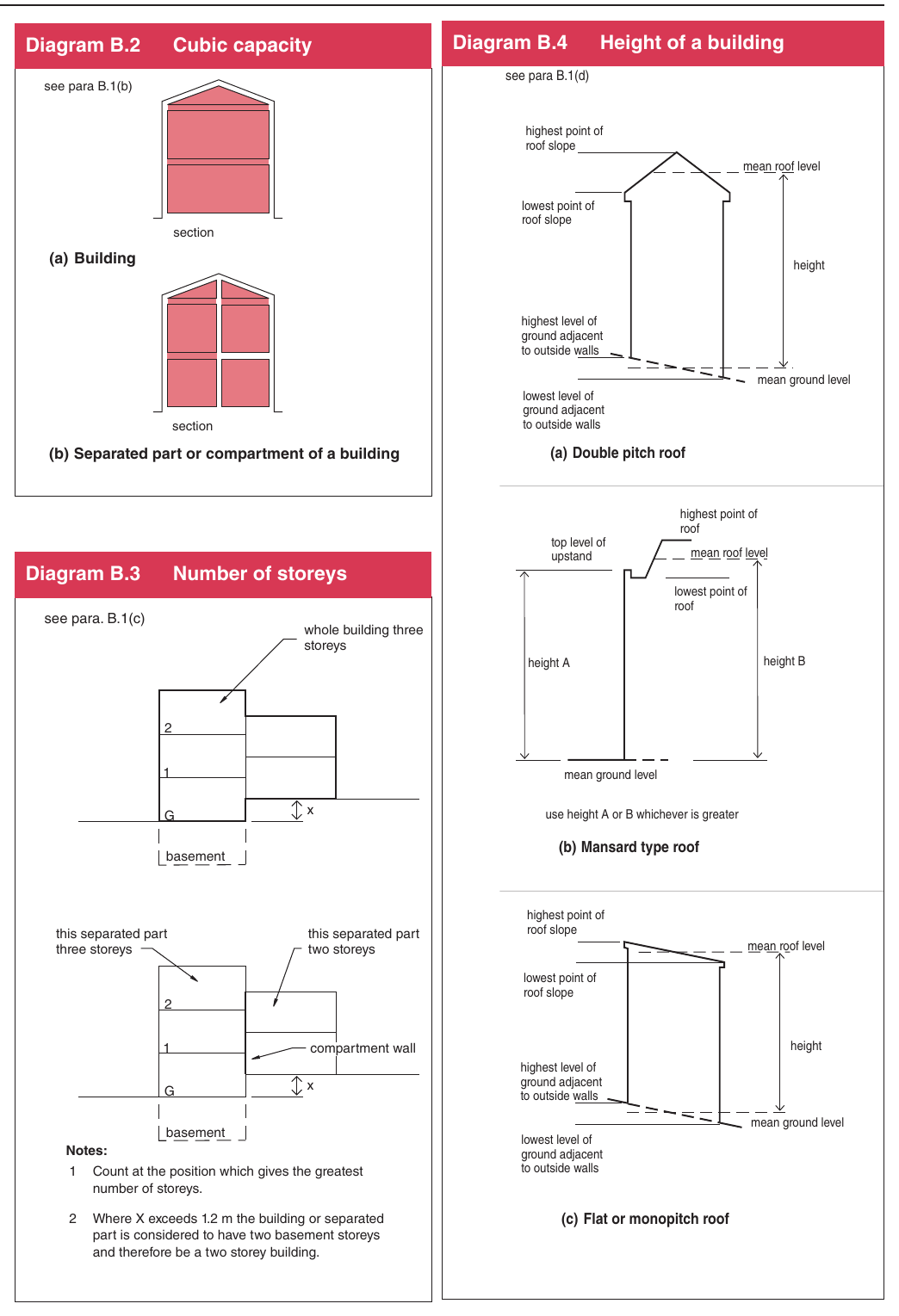
Page 185
#Source page 185
| Diagram B.5 Height to a storey and dept | h of a basement | |
|---|---|---|
| see para B.1(e) and B.1(f) height to top storey excludes roof top plant areas and any top storeys consisting exclusively of plant rooms roof height to a storey lowest level of ground adjacent to outside walls | plant | highest level of ground adjacent to outside walls depth of a basement |
| Diagram B.6 Width of a doorway | |
| see paras 2.92 and B.1(g) effective clear width when door opens to 90º | effective clear width when door opens more than 90 º |
Page 186
#Source page 186
Appendix C Publications referred to
BS EN ISO 306: 2004 Plastics. Thermoplastic materials. Determination of Vicat softening temperature (VST).
BS EN ISO 1182: 2002 2020 Reaction to fire tests for building products. Non-combustibility test.
BS EN ISO 1716: 2002 2018 Reaction to fire tests for building products. Determination of the gross heat of combustion (calorifc value).
BS EN ISO 11925 Reaction to fire tests. Ignitability of building products subjected to direct impingement of flame
Part 2: 2002 2020 Single-flame source test.
BS EN 54-11: 2001 Fire detection and fire alarm systems
Part 11: 2001 Manual call points AMD 16126 June 2006 AMD 16487 June 2006.
BS EN 81-1: 1998 Safety rules for the construction and installation of lifts
Part 1: Electric lifts.
BS EN 81-2: 1998 Safety rules for the construction and installation of lifts
Part 2: Hydraulic lifts.
BS EN 81-20: 2020 Safety rules for the construction and installation of lifts
Part 20: Lifts for the transport of persons and goods. Passenger and goods passenger lifts
BS EN 81-58: 2003 2022 Safety rules for the construction and installation of lifts. Examination and tests.
Part 58: Landing doors fire resistance test.
BS EN 81-70: 2020 Safety rules for the construction and installation of lifts
Part 70: Particular applications for passenger and goods passenger lift. Accessibility to lifts for persons including persons with disability. A1:2022
BS EN 81-72: 2003 2020 Safety rules for the construction and installation of lifts. Particular applications for passenger and goods passenger lifts
Part 72: Firefighters lifts.
Page 187
#Source page 187
BS EN 771-3: 2003 2011Specification for masonry units
Part 3: 2003 2011 Aggregate concrete masonry units (dense and lightweight aggregates) AMD 16001 February 2006. A1; 2015
BS EN 1125: 2008 Building hardware. Panic exit devices operated by a horizontal bar, for use on escape routes. Requirements and test methods.
BS EN 1363 Fire resistance tests
Part 1: 1999 2020 General requirements Part 2: 1999 Alternative and additional procedures.
BS EN 1364 Fire resistance tests for non-loadbearing elements
Part 1: 1999 2015 Walls Part 2: 1999 2018 Ceilings.
BS EN 1365 Fire resistance tests for loadbearing elements
Part 1: 1999 2012 Walls Part 2: 2000 2014 Floors and roofs Part 3: 2000 Beams Part 4: 1999 Columns.
BS EN 1366 Fire resistance tests for service installations
Part 1: 1999 2014 Ventilation ducts Ducts Part 2: 1999 2015 Fire dampers.
BS EN 1634: 2004 Fire resistance and smoke control tests for door and shutter assemblies, openable windows and elements of building hardware
Part 3: Smoke control test for door and shutter assemblies.
BS EN 1634: 2008 Fire resistance and smoke control tests for door, shutter and openable window assemblies and elements of building hardware
Part 1: 2014 Fire resistance tests for doors, shutters and openable windows.
A1:2018
Part 2: Fire resistance characterisation test for elements of building hardware.
BS EN 1993-1-2: 2005 Eurocode 3. Design of steel structures. General rules.
BS EN 12101-6: 2005 2022 Smoke and heat control systems
Part 6: Specification for pressure differential systems. Kits.
Page 188
#Source page 188
BS EN 12101-8: 2011 Smoke and heat control systems
Part 8: Smoke control dampers
BS EN 12845: 2004 2015 Fixed firefighting systems. Automatic sprinkler systems. Design, installation and maintenance.
A1:2019
BS EN 13238: 2001 Reaction to fire tests for building products. Conditioning procedures and general rules for selection of substrates.
BS EN 13501 Fire classification of construction products and building elements
Part 1: 2007 2018 Classification using test data from reaction to fire tests
Part 2: 2007 Classification using data from fire resistance and/or smoke control tests, excluding ventilation services
Part 3: 2005 Classification using data from fire resistance tests on products and elements used in building service installations: fire resisting ducts and fire dampers
A1:2009
Part 5: 2005 2016 Classification using data from external fire exposure to roofs tests.
BS EN 13823: 2002 2020 Reaction to fire tests for building products. Building products excluding floorings exposed to the thermal attack by a single burning item.
A1:2022
BS EN 14604: 2005 Smoke alarm devices.
BS EN 15725:2010 Extended application reports on fire performance of construction products and building elements
BS EN 50200: 2006 Method of test for resistance to fire of unprotected small cables for use in emergency circuits.
DD ENV 1187: 2002, test 4 Test methods for external fire exposure to roofs
AMD 16344 May 2006.
BS 476: Fire tests on building materials and structures
Part 3: 1958 External fire exposure roof test Part 3: 2004 Classification and method of test for external fire exposure to roofs
Part 4: 1970 (1984) Non-combustibility test for materials AMD 2483 March 1978 AMD 4390 September 1983
Part 6: 1981 Method of test for fire propagation for products AMD 4329 Part 6: 1989 Method of test for fire propagation for products
Page 189
#Source page 189
Part 7: 1971 Surface spread of flame tests for materials Part 7: 1987 (1993) Method for classification of the surface spread of flame of products
AMD 6249 January 1990 AMD 7030 January 1992 AMD 7612 April 1993
Part 7: 1997 Method of test to determine the classification of the surface spread of flame of products Part 8: 1972 Test methods and criteria for the fire resistance of elements of building construction AMD 1873 January 1976 AMD 3816 November 1981 AMD 4822 May 1985 Part 11: 1982 (1988) Method for assessing the heat emission from building materials Part 20: 1987 Method for determination of the fire resistance of elements of construction (general principles) AMD 6487 April 1990 Part 21: 1987 Methods for determination of the fire resistance of loadbearing elements of construction Part 22: 1987 Methods for determination of the fire resistance of non-loadbearing elements of construction Part 23: 1987 Methods for determination of the contribution of components to the fire resistance of a structure Part 24: 1987 Method for determination of the fire resistance of ventilation ducts Section 31.1: 1983 Methods for measuring smoke penetration through doorsets and shutter assemblies. AMD 8366
BS 747: 1977 (1986) Specification for roofing felts
AMD 3775 November 1981 AMD 4609 February 1985 AMD 5101 February 1986.
BS 2782: Method of testing plastic
Part 0: 2004 Introduction.
BS 4514: 2001 Unplasticized PVC soil and ventilating pipes of 82.4mm minimum mean outside diameter, and fittings and accessories of 82.4mm and of other sizes. Specification. 1983 Specification for unplasticized PVC soil and ventilating pipes, fittings and accessories
AMD 4517 June 1984 AMD 5584 November 1987.
BS 5255: 1989 Specification for thermoplastics waste pipe and fittings.
Page 190
#Source page 190
BS 5266: Emergency lighting
Part 1: 2005 2016 Code of practice for the emergency lighting of premises.
BS 5306: Fire extinguishing installations and equipment on premises
Part 1: 1976 (1988) Hydrant systems, hose reels and foam inlets
AMD 4649 August 1984
AMD 5756 February 1988
Part 2: 1990 Specification for sprinkler systems
AMD 9809 January 1998
AMD 9985 April 1998.
BS 5395: Stairs, ladders and walkways
Part 2: 1984 Code of practice for the design of helical and spiral stairs AMD 6076 July 1989.
BS 5438: 1989 Methods of test for flammability of textile fabrics when subjected to a small igniting flame applied to the face or bottom edge of vertically oriented specimens
AMD 6509 June 1990 AMD 8308 December 1994.
BS 5446: Fire detection and fire alarm devices for dwellings
Part 1: 2000 Specifications for smoke alarms
Part 2: 2003 Specification for heat alarms.
BS 5499: Graphical symbols and signs – Safety signs, including fire safety signs
Part 1: 2002 Specification for geometric shapes, colours and layout Part 4: 2000 2013 Code of practice for escape route signing AMD 12082 November 2000.
BS 5588: Fire precautions in the design, construction and use of buildings
Part 1: 1990 Code of practice for residential buildings
AMD 7840 September 1993
AMD 14988 December 2004
Part 4: 1998 Code of practice for smoke control using pressure differentials
AMD 10019 April 1998
AMD 13868 December 2002
AMD 14989 December 2004
Part 5: 2004 Access and facilities for fire-fighting
Part 6: 1991 Code of practice for places of assembly
AMD 10212 December 1998
AMD 10443 August 1999
AMD 14990 December 2004
Page 191
#Source page 191
Part 7: 1997 Code of practice for the incorporation of atria in buildings AMD 10546 August 1999 AMD 14991 December 2004
Part 8: 1999 Code of practice for means of escape for disabled people AMD 14992 December 2004 Part 9: 1999 Code of practice for ventilation and air conditioning ductwork AMD 14993 December 2004 Part 10: 1991 Code of practice for shopping complexes AMD 14994 December 2004.
BS 5839: Fire detection and fire alarm systems for buildings
Part 1: 2017 Code of practice for design, installation, commissioning and maintenance of systems in non-domestic premises 2002 + A2: 2008 Code of practice for system design, installation, commissioning and maintenance
AMD 15447 December 2004 A2 March 2008 Part 3: 1988 Specification for automatic release mechanisms for certain fire protection equipment AMD 10207 November 1998 AMD 17256 July 2007
Part 6: 2004 2019 Code of practice for the design, installation and maintenance of fire detection and fire alarm systems in dwellings
A1October 2020
Part 8: 1998 2023 Design, installation, commissioning and maintenance of voice alarm systems. Code of practice Code of practice for the design, installation, commissioning and maintenance of voice alarm systems
Part 9: 2003 2021 Code of practice for the design, installation, commissioning and maintenance of emergency voice communication systems.
BS 5867: Specification for fabrics for curtains and drapes
Part 2: 1980 (1993) Flammability requirements AMD 4319 July 1983.
BS 5950: Structural use of steelwork in building
Part 8: 2003 Code of practice for fire resistant design.
BS 6387: 1994 2013 Test method for resistance to fire of cables required to maintain circuit integrity under fire conditions Specification for performance requirements for cables required to maintain circuit integrity under fire conditions.
BS 7346: Components for smoke and heat control systems
Part 6: 2005 Specification for cable systems.
BS 7974: 2001 2019 Application of fire safety engineering principles to the design of buildings – Code of practice.
Page 192
#Source page 192
BS 8629: 2019 Code of practice for the design, installation, commissioning and maintenance of evacuation alert systems for use by fire and rescue services in buildings containing flats.
A1March 2023
BS 9990: 2006 2015 Code of practice for non-automatic fire-fighting systems in buildings.
BS 9251: 2021 Fire sprinkler systems for domestic and residential occupancies Code of practice.
BS 9991: 2015 Fire safety in the design, management and use of residential buildings. Code of practice.
BS 9999: 2008 2017 Code of practice for fire safety in the design, management and use of buildings.
BR 128: 1988 Guidelines for the construction of fire-resisting structural elements.
BR 135: 1988 2013 Third edition Fire performance of external thermal insulation for walls of multi-storey buildings.
BR 187: 1991 External fire spread: building separation and boundary distances.
BR 368: 1999 Design methodologies for smoke and heat exhaust ventilation.
Building Bulletin 100: Design for fire safety in schools: published by the Department for Children, schools and families.
Code of Practice for the Provision of Premises Information Boxes in Residential Buildings’ published by the Fire Industry Association (FIA).
DOE Circular 12/92 Houses in multiple occupation.
Fire performance of Green roofs and walls 2013 published by MHCLG.
Houses in multiple Occupation, Fire Safety Guide v2 2020, published by Northern Ireland Fire and Rescue Service.
HTM 05-02 Firecode – guidance in support of functional provisions (fire safety in the design of healthcare premises) published by Department of Health England.
The Fire and Rescue Services (Northern Ireland) Order 2006.
The Fire Safety Regulations (Northern Ireland) 2010.
Guide to fire precautions in premises used as hotels and boarding houses which require a fire certificate: published by the Home Office.
Guide to undertaking technical assessments of fire performance of construction products based on fire test evidence: published by Passive Fire Protection Forum 2021.
Page 193
#Source page 193
The International Association of Cold Storage Contractors (European Division): Design, construction, specification and fire management of insulated envelopes for temperature controlled environments: Second Edition 2008.
The Northern Ireland Guide to safety at sports grounds: 2007 published by the Department of Culture, Arts and Leisure.
Northern Ireland Firecode: November 2010.
Safety signs and signals: guidance on regulations: Second edition 2009: published by Health and Safety Executive.
The Steel Construction Institute 2002: Fire and steel construction: Single Storey Steel Framed Buildings in Fire Boundary Conditions.
DFP Technical Booklet B: 2012 Materials and workmanship
Page 194
#Source page 194
Commission decisions
Commission Decision 96/603/EC of 4th October 1996 implementing Council Directive 89/106/EEC.
Commission Decision 94/611/EC implementing Article 20 of the Council Directive 89/106/EEC.
Commission Decision 200/147/EC of 8 Feb 2000 implementing Council Directive 89/106/EEC.
Commission Decision 2000/367/EC OF 3 May 2000 implementing Council Directive 89/106/EEC.
European Parliament Council Directive 95/16/EC of 29 June 1995 implementing the Lifts Regulations 1997.
Commission Decision 2005/823/EC amending Decision 2001/671/EC establishing a classification system for the external fire performance of roofs and roof coverings.
Commission Decision 2000/553/EC implementing Council Directive 89/106/EEC as regards the external fire performance of roof coverings.
Commission Decision 2003/424/EC and 2000/605/EC amending decision 96/603/EC establishing the list of products belonging to class A1 ‘Nocontribution to fire’ provided for in the Decision 94/611/EC implementing Article 20 of the Council Directive 89/106/EEC on construction products.
Commission Decision 2005/823/EC amending Decision 2001/671/EC implementing Council Directive 89/106/EEC as regards the classification system for the external fire performance of roofs and roof coverings.
Commission Decision 2000/553/EC implementing Council Directive 89/106/EEC as regards the external fire performance of roof coverings.
Page 195
#Source page 195
Technical Booklets
The following list comprises the series of Technical Booklets prepared by the Department for the purpose of providing practical guidance with respect to the technical requirements of the Building Regulations (Northern Ireland)
2012.
Technical Booklet B Technical Booklet C
Technical Booklet D Technical Booklet E Technical Booklet F1 Technical Booklet F2
Technical Booklet G Technical Booklet H
Technical Booklet J Technical Booklet K Technical Booklet L
Technical Booklet M
Technical Booklet N Technical Booklet P
Technical Booklet R Technical Booklet V Materials and workmanship
Preparation of site and resistance to contaminants and moisture Structure Fire safety Conservation of fuel and power in dwellings Conservation of fuel and power in buildings other than dwellings Resistance to the passage of sound Stairs, ramps, guarding and protection from impact Solid waste in buildings Ventilation Combustion appliances and fuel storage systems
Physical infrastructure for high-speed electronic communications network
Drainage
Sanitary appliances, unvented hot water storage systems and reducing the risk of scalding Access to and use of buildings Glazing
Any person who intends to demonstrate compliance with the Building Regulations by following the guidance given in a Technical Booklet is advised to ensure that the guidance is current on the date when plans are deposited or notice given to the district council.