Northern Ireland Technical booklet G
Technical booklet G - Resistance to the passage of sound - October 2012
Library captured 10 September 2026 · Source updated 25 August 2026
● Finance and ● Personnel
#Source page 1
Department of
● Finance and ● Personnel
G u i d a n c e
Te c h n i c a l B o o k l e t
G
Resistance to the passage of sound
October 2012
Page 2
#Source page 2
Contents page Introduction 2
Part G Regulations 6
Guidance Performance and introduction to provisions 8
Section 2 Separating walls and associated flanking constructions for new buildings 25
Section 3 Separating floors and associated flanking constructions for new buildings 62
Section 4 Dwellings formed by material change of use 89
Section 5 Internal walls and floors for new buildings 100
Section 6 Rooms for residential purposes 105
Section 7 Reverberation in the common internal parts of buildings containing flats, maisonettes or rooms for residential purposes 108
Appendix A Method for calculating mass per unit area 113
Appendix B Procedures for sound insulation testing 117
Appendix C Publications referred to 123
Appendix D Design details approved by Robust Details Ltd 125
Technical Booklets
#Source page 3
Introduction
Technical Booklets
This Technical Booklet, which takes effect on 31st October 2012, is one of a series that has been prepared by the Department of Finance and Personnel (the Department) for the purpose of providing practical guidance with respect to the technical requirements of the Building Regulations (Northern Ireland) 2012 (the Building Regulations).
At the back of each Technical Booklet is a list of all the Technical Booklets that have been prepared and published by the Department for this purpose.
The guidance given in a Technical Booklet includes performance standards and design provisions relating to compliance with specific aspects of the Building Regulations for the more common building situations.
If the guidance in a Technical Booklet is followed there will be a presumption of compliance with the requirements of those Building Regulations covered by that guidance. However, this presumption can be overturned, so simply following the guidance does not guarantee compliance. For example, if a particular circumstance is not one of the more common building situations the design provisions given in the Technical Booklet may not be appropriate.
There are likely to be alternative ways of demonstrating compliance with the relevant requirements of the Building Regulations other than by following a design provision given in a Technical Booklet. There is therefore no obligation to adopt any particular provision set out in a Technical Booklet, should you decide to comply in some other way. However, you will have to demonstrate that your alternative solution meets the relevant requirements of the Building Regulations by those other means.
This Technical Booklet
Requirements
The guidance contained in this Technical Booklet relates only to the requirements of regulations 49, 50, 51, 52 and 53. The work will also have to comply with all other relevant requirements of the Building Regulations.
Materials and workmanship
Any building work which is subject to requirements imposed by Part A of the Building Regulations should be carried out in accordance with regulation 23 of those regulations. Guidance on meeting these requirements for materials and workmanship is given in Technical Booklet B which supports Part B.
The Building Regulations are made for specific purposes, primarily securing the health, safety, welfare and convenience of people and for the conservation of fuel and power. Standards and technical approvals are relevant guidance to the extent that they relate to these purposes. However, they may also address other aspects of performance such as serviceability, or aspects which although they relate to health and safety are not covered by the Building Regulations.
Named standards
#Source page 4
Where this Technical Booklet makes reference to a named standard, the relevant version of the standard is the one listed in Appendix C. However, if this version has been replaced or updated by the issuing standards body, the new version may be used as a source of guidance provided that it continues to address the relevant requirements of the Building Regulations.
Diagrams
The diagrams in this Technical Booklet supplement the text. They do not show all the details of construction and are not intended to illustrate compliance with any other requirement of the Building Regulations. They are not necessarily to scale and should not be used as working details.
Protected buildings
District councils have a duty to take account of the desirability to preserve the character of protected buildings when carrying out their functions under Building Regulations. Therefore, where work is to be carried out to a protected building to comply with Part G or any other Part of the Building Regulations, special consideration may be given to the extent of such work for compliance where it would unacceptably alter the character or appearance of the building. Protected buildings are defined in Article 3A(2) of the Building Regulations (Northern Ireland) Order 1979 (as amended).
Other legislation
The provisions of this Technical Booklet relate to the requirements of Building Regulations and do not include measures which may be necessary to meet the requirements of other legislation. Such other legislation may operate during the design or construction stages or when a building is brought into use and can extend to cover aspects which are outside the scope of the Building Regulations.
The Workplace (Health, Safety and Welfare) Regulations (Northern Ireland) 1993
The Workplace (Health, Safety and Welfare) Regulations (Northern Ireland) 1993 (the Workplace Regulations) contain some requirements which affect building design. The main requirements are now covered by the Building Regulations, but for further information see – The Workplace Regulations and the Workplace Health, Safety and Welfare Approved Code of Practice.
The Workplace Regulations apply to the common parts of flats and similar buildings if people such as cleaners, wardens and caretakers are employed to work in these common parts. Where the requirements of the Building Regulations that are covered by Part G do not apply to dwellings, the provisions may still be required in the situations described above in order to satisfy the Workplace Regulations.
Environmental noise
#Source page 5
The requirements of Part G do not address environmental noise through the building facade from sources such as aircraft, trains, road traffic or industry. Other legislation covers these areas.
The EU Directive 2002/49/EC relating to assessment and management of environmental noise, commonly referred to as the Environmental Noise Directive (END), was published in July 2002. The END was implemented in Northern Ireland by the Environmental Noise Regulations (Northern Ireland) 2006.
Environmental Noise Regulations (Northern Ireland) 2006 (the Regulations)
The Environmental Noise Regulations came into force on 20 October 2006. They apply to environmental noise in builtup areas, public parks or other quiet areas in agglomerations (large urban areas) and other noise sensitive buildings and areas. The Regulations apply to noise from road, railway and airport sources, as well as industrial noise. They do not apply to noise caused by the person exposed, from domestic or work activities or from neighbours.
Under the Regulations and Directive certain authorities (for Northern Ireland DOENI) are required to compile noise maps showing the noise occurring in a particular area, whether from particular stretches of road or rail or airports or industrial sources.
Following the analysis of the noise maps the authorities identify the noise pollution priorities and develop Action Plans which can require the implementation of measures to reduce or preserve noise in a given area.
Page 6
#Source page 6
Technical Booklet G: 2012 Resistance to the passage of sound 5
PART G
#Source page 7
Part G Regulations
Part G (comprising regulations 48 – 53) of the Building Regulations which sets out the requirements for the resistance to the passage of sound in buildings, has been replicated below for the convenience of the user of this Technical Booklet and is taken directly from the Building Regulations (Northern Ireland) 2012.
Any person who intends to demonstrate compliance with the Building Regulations by following the guidance given in this Technical Booklet is advised to ensure that the regulations below are current on the date when plans are deposited or notices given to the district council.
As Part A (comprising regulations 1 – 21) of the Building Regulations sets out the interpretation along with the procedural requirements relating to the application of the regulations, the Department advises that all Parts of the Building Regulations be read in conjunction with Part A of those regulations.
The Building Regulations (Northern Ireland) 2012 and any subsequent amendment may be viewed by following the links from the Department’s website at “www.buildingregulationsni.gov.uk”.
PART G
Resistance to the passage of sound
Application and interpretation
48.—(1) Regulation 50 shall not apply to—
(a)an internal wall that contains a door;
(b)an internal wall that separates an ensuite toilet from the associated bedroom; or
(c)existing walls and floors in a building that is subject to material change of use.
(2)Regulation 51 applies only to corridors, stairwells, hallways or entrance halls that give access to a flat or to a room for residential purposes.
(3)Regulation 53—
(a)applies only where regulation 49 imposes a requirement; and
(b)shall not apply where the walls and floors are designed and constructed to comply with regulation 49 using design details approved by the Department.
(4)In this Part—
“Reverberation” means the persistence of sound in a space after the sound source has been stopped; and
“School building” means any building forming a school or part of a school.
Protection against sound from other parts of the building and from adjoining buildings
49.A dwelling or room for residential purposes shall be designed and constructed in such a way so as to provide reasonable resistance to the passage of sound from other parts of the same building outside the dwelling or room for residential purposes and from adjoining buildings.
Page 8
#Source page 8
Protection against sound within a dwelling or room for residential purposes
50.Within a dwelling or room for residential purposes reasonable resistance to the passage of airborne sound shall be provided by—
(a) internal walls that separate—
(i)a bedroom; and
(ii)a room containing a water closet,
from any other room; and
(b) all internal floors.
Reverberation in the common internal parts of buildings containing flats or rooms for residential purposes
51.Any common internal part of a building that contains a flat or a room for residential purposes shall be designed and constructed in such a way as to limit reverberation around those common parts to a reasonable level.
Acoustic conditions in schools
52.Each room or space in a school building shall be designed and constructed in such a way that it has—
(a) acoustic conditions; and
(b) reasonable resistance to the passage of sound, appropriate to its intended use.
Sound insulation testing and notice of results
53.Where this regulation applies, the person carrying out the work shall for the purposes of ensuring compliance with regulation 49—
(a)ensure that appropriate sound insulation testing is carried out in accordance with a procedure approved by the Department; and
(b)not more than 5 days after completion of the testing give a notice in writing to the district council stating the results of the sound insulation testing referred to in subparagraph (a).
Relevant definitions in regulation 2 in Part A of the Building Regulations
“Dwelling” “Flat” “Room for residential purposes” “School”
Protection against sound from other parts of the building and from adjoining buildings
#Source page 9
Guidance Performance and introduction to provisions
Protection against sound from other parts of the building and from adjoining buildings
Performance
0.1It is the view of the Department that the requirements of regulation 49 will be met in a dwelling or room for residential purposes where adequate provisions are made in the design and construction of separating walls, separating floors and stairs that have a separating function, together with their associated flanking construction, to limit the passage of sound –
(a)from other parts of the same building; and
(b)from adjoining buildings.
Introduction to provisions in Sections 2, 3, 4 and 6 of this Technical Booklet
0.2Section 2 – Separating walls and associated flanking constructions for new buildings, gives a range of wall constructions which, if properly designed and constructed, should provide reasonable resistance to the passage of airborne and flanking sound.
Section 3 – Separating floors and associated flanking constructions for new buildings, gives a range of floor constructions which, if properly designed and constructed, should provide reasonable resistance to the passage of airborne, impact and flanking sound.
Section 4 – Dwellings formed by material change of use, gives one wall treatment, two alternative floor treatments and one stair treatment which, if properly designed and constructed, should provide reasonable resistance to the passage of airborne, impact and flanking sound.
Section 6 – Rooms for residential purposes, gives a range of wall and floor constructions which, if properly designed and constructed, should provide reasonable resistance to the passage of airborne, impact and flanking sound.
Protection against sound within a dwelling or room for residential purposes
Performance
0.3It is the view of the Department that the requirements of regulation 50 will be met in a dwelling or room for residential purposes where reasonable provisions are made in the design and construction of internal walls and floors to limit the passage of sound –
(a)through internal walls between a bedroom or a room containing a water closet, and other rooms; and
(b)through internal floors.
Introduction to provisions in Section 5 of this Technical Booklet
#Source page 10
0.4Section 5 – Internal walls and floors for new buildings, gives a range of wall and floor constructions which, if properly designed and constructed, should provide reasonable resistance to the passage of sound within the dwelling or room for residential purposes.
Reverberation in the common internal parts of buildings containing flats, maisonettes and rooms for residential purposes
Performance
0.5It is the view of the Department that the requirements of regulation 51 will be met in a flat, maisonette or room for residential purposes where reasonable provisions are made to limit the reverberation of sound in any common internal parts of the building.
Introduction to provisions in Section 7 of this Technical Booklet
0.6Section 7 – Reverberation in the common internal parts of buildings containing flats, maisonettes and rooms for residential purposes, gives guidance on how to determine the amount of additional absorption that needs to be provided in corridors, hallways, stairwells and entrance halls that give access to flats, maisonettes and rooms for residential purposes.
Acoustic conditions in schools
Performance
0.7It is the view of the Department that the requirements of regulation 52 will be met in each room or space in a school building where reasonable provisions are made to provide acoustic conditions and adequate resistance to the passage of airborne, impact and flanking sound appropriate to the intended use of the room or space in the school.
Introduction to acoustic conditions in schools
0.8Acoustic conditions in schools is a specialist area and guidance on addressing sound insulation, reverberation time and indoor ambient noise in schools is given in Section 1 of Building Bulletin 93: Acoustic Design of Schools produced by the Department for Education and Skills (DfES) in England and Wales.
Testing for sound insulation
Performance
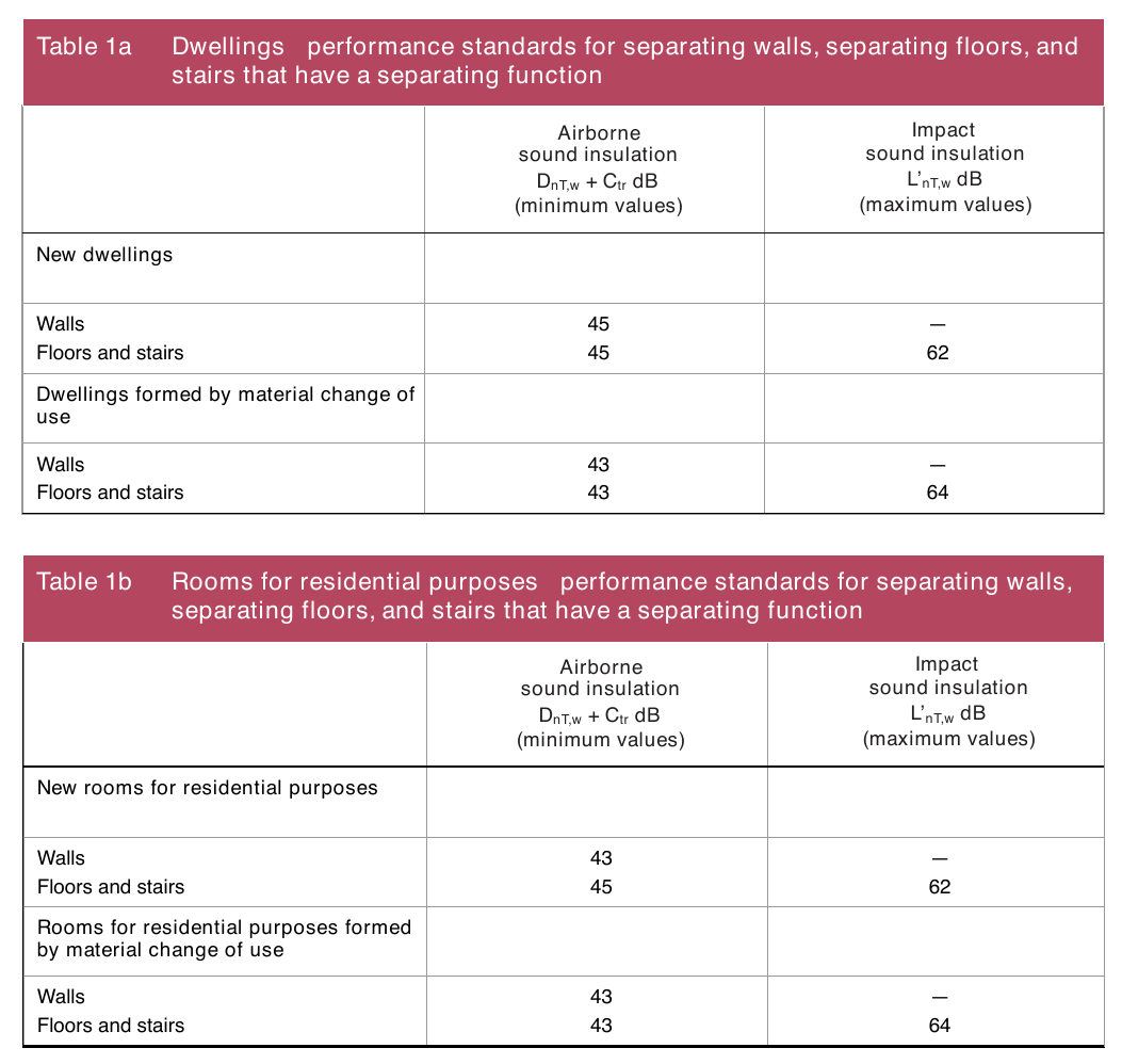
0.9It is the view of the Department that the requirements of regulation 53 will be met for a dwelling or room for residential purposes where sound insulation testing demonstrates that the sound insulation standards given in Table 1a and Table 1b in this Technical Booklet have been achieved.
Introduction to precompletion testing
#Source page 11
Table 1a Dwellings performance standards for separating walls, separating floors, and
| Airborne sound insulation DnT,w + C tr dB (minimum values) s ( A | D ( Impact sound insulation L’ nT,w dB (maximum values) | |
| New dwellings | ||
| Walls Floors and stairs | 45 45 | — 62 |
| Dwellings formed by material change of use | ||
| Walls Floors and stairs | 43 43 | — 64 |
| Airborne sound insulation D nT,w + C tr dB (minimum values) s ( A | D ( Impact sound insulation L’ nT,w dB (maximum values) | |
| New rooms for residential purposes | ||
| Walls Floors and stairs | 43 45 | — 62 |
| Rooms for residential purposes formed by material change of use | ||
| Walls Floors and stairs | 43 43 | — 64 |
Introduction to precompletion testing
0.10Precompletion testing, for new dwellings and rooms for residential purposes (including those formed as a result of material change of use) gives the standards to be achieved, the test procedures, the grouping of properties by type and the manner of recording the results of the sound insulation test.
Notice of sound insulation test
Performance
0.11It is the view of the Department that the requirements of regulation 53 will be met for a dwelling or room for residential purposes where notice of any sound insulation test is given to the district council in writing not more than 5 days after completion of the test.
Introduction to the sound insulation test
#Source page 12
Performance
0.12Precompletion testing, together with Appendix B: Procedures for sound insulation testing, defines the procedures that should be followed to conduct a sound insulation test of the dwelling or room for residential purposes. Paragraph 1.42 sets the approved manner of recording the results of the precompletion test that must be notified to the district council in writing not more than 5 days after completion of the test.
0.13It is the view of the Department that the requirements of Part G will be met if separating walls, separating floors, and stairs that have a separating function, together with the associated flanking construction, are built in such a way that they achieve the sound insulation values for dwellings set out in Table 1a, and the values for rooms for residential purposes set out in Table 1b.
For walls that separate rooms for residential purposes from adjoining dwellings, the performance standards given in Table 1a should be achieved.
0.14The Building Regulations Northern Ireland 2012 apply to building work to which Part G applies, and require appropriate sound insulation testing to be carried out. The exception is that, in the case of newbuild houses and buildings containing flats and maisonettes, testing will not apply to any relevant part of the building where the design embodies a design detail or details from the set approved and published by Robust Details Ltd; a valid notification is given to the district council; and the actual work complies with the detail or details specified in the notification. Subject to this exception, which is further explained in Appendix D: Design details approved by Robust Details Ltd, it is the view of the Department that where testing applies it will be met through the implementation of a programme of sound insulation testing according to the guidance set out in Section1: Precompletion testing, of this Technical Booklet.
It is possible for a builder to opt to use design details approved by Robust Details Ltd in only some of the relevant separating structures in a new house or building containing flats and maisonettes, with the other relevant separating structures remaining subject to testing.
It is recommended that expert advice is sought to ensure compatibility of constructions where Robust Details Ltd design details are used in conjunction with details designed by others.
0.15The sound insulation testing should be carried out in accordance with the procedure described in Appendix B of this Technical Booklet. The results of the testing must be recorded in the manner described in paragraph 1.42 of this Technical Booklet. The test results must be given to the district council in accordance with the time limits set by the regulations.
0.16Sound insulation testing should be carried out by a person who is registered to test the specific class of building concerned. Sound insulation testing is to be carried out by a test body with appropriate third party accreditation. Test bodies conducting testing should preferably have UKAS accreditation (or a European equivalent) for field measurements. The Department also regards members of the Association of Noise Consultants Registration Scheme as suitably qualified to carry out precompletion testing.
Page 13
#Source page 13
0.17Sections 2 and 3 of this Technical Booklet give examples of constructions which, if built correctly, should when tested achieve the sound insulation values for dwellings and rooms for residential purposes set out in Tables 1a and 1b. The guidance in these sections is not exhaustive and other designs, materials or products may be used to achieve the required performance.
0.18Buildings constructed from subassemblies that are delivered newly made or selected from stock are no different from any other new building and must comply with all requirements in the Building Regulations (Northern Ireland) 2012. In some applications, such as buildings that are constructed to be temporary dwellings, rooms for residential purposes, or school buildings, the provision of reasonable resistance to the passage of sound may vary depending upon the circumstances in the particular case. For example, a building created by dismantling, transporting and reerecting the sub assemblies on the same premises would normally be considered to meet the requirements.
0.19In the case of some historic buildings undergoing material change of use, it may not be practical to improve the sound insulation to the standards set out in Tables 1a and 1b. The need to conserve the special characteristics of such historic buildings needs to be recognised, and in such work, the aim should be to improve sound insulation to the extent that is practically possible, always provided that the work does not prejudice the character of the historic building, or increase the risk of longterm deterioration to the building fabric or fittings. In arriving at an appropriate balance between historic building conservation and improving sound insulation it would be appropriate to take into account the advice of the Northern Ireland Environment Agency Built Heritage conservation officer. In such cases it will be reasonable to improve the sound insulation as much as is practical, and to supply a notice showing the sound insulation value(s) obtained by testing to the building owner upon completion.
0.20The performance standards set out in Tables 1a and 1b are appropriate for walls, floors and stairs that separate spaces used for normal domestic purposes. Specialist advice may be needed to establish if a higher standard of sound insulation is required between spaces used for normal domestic purposes and communal or nondomestic purposes. In these situations the appropriate level of sound insulation will depend on the noise generated in the communal or nondomestic space.
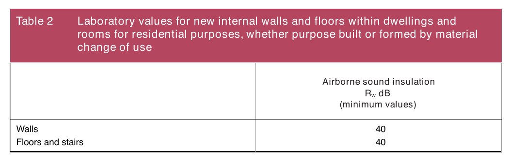
0.21It is the view of the Department that the requirements of regulation 50 will be met by the use of constructions for new walls and floors within a dwelling or room for residential purposes that provide the laboratory sound insulation values set out in Table 2. Test bodies conducting testing should preferably have UKAS accreditation (or a European equivalent) for laboratory measurements. It is not intended that performance should be verified by testing on site.
0.22Section 5 gives examples of constructions that should achieve the laboratory values set out in Table 2. The guidance in these sections is not exhaustive and other designs, materials or products may be used to achieve the required performance.
Page 14
#Source page 14
Table 2 Laboratory values for new internal walls and floors within dwellings and
0.23It is the view of the Department that the requirements of regulation 51 will be met by the use of sound absorption measures described in Section 7 of this Technical Booklet, or other measures of similar effectiveness.
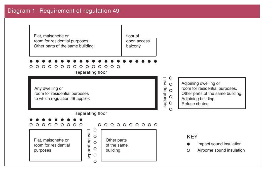
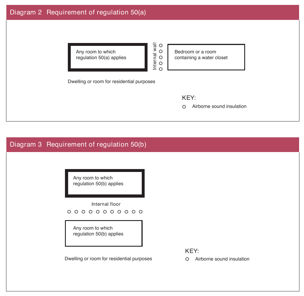
0.24Diagrams 1 to 3 illustrate the relevant parts of the building that should be protected from airborne and impact sound in order to satisfy regulations 49 and 50.
Diagram 1 Requirement of regulation 49
Page 15
#Source page 15
Diagram 2 Requirement of regulation 50(a)
0.25It is the view of the Department that the requirements of regulation 52 will be met by demonstrating compliance with the values for sound insulation, reverberation time and indoor ambient noise which are given in Section 1 of Building Bulletin 93: Acoustic Design of Schools, produced by DfES and published by The Stationery Office (ISBN 9780112711056).
Definitions
#Source page 16
Section 1 General
Definitions
1.1In this Technical Booklet the following definitions apply –
Absorption – conversion of sound energy to heat, often by the use of a porous material.
Absorption coefficient – a quantity characterising the effectiveness of a sound absorbing surface. The proportion of sound energy absorbed is given as a number between zero (for a fully reflective surface) and one (for a fully absorptive surface). Note that sound absorption coefficients determined from laboratory measurements may have values slightly larger than one. See BS EN 20354.
Absorptive material – material that absorbs sound energy.
Airborne sound – sound propagating through the air.
Airborne sound insulation – sound insulation that reduces transmission of airborne sound between buildings or parts of buildings.
Air path – a direct or indirect air passage from one side of a structure to the other.
Caulking – Process of sealing joints.
Cavity stop – a proprietary product or a material such as mineral wool used to close the gap in a cavity wall to control flanking transmission.
Ctr – the correction to a sound insulation quantity (such as DnT,w) to take account of a specific sound spectrum. See BS EN ISO 7171.
Decibel (dB) – the unit used for many acoustic quantities to indicate the level with respect to a reference level.
Density – mass per unit volume, expressed in kilograms per cubic metre (kg/m3).
Direct transmission – the process in which sound that is incident on one side of a building element is radiated by the other side.
DnT – the difference in sound level between a pair of rooms, in a stated frequency band, corrected for the reverberation time. See BS EN ISO 1404.
DnT,w – a singlenumber quantity which characterises the airborne sound insulation between rooms. See BS EN ISO 7171.
DnT,w + Ctr – a singlenumber quantity which characterises the airborne sound insulation between rooms using noise spectrum no. 2 as defined in BS EN ISO 7171.
Dwelling – is defined in regulation 2 in Part A of the Building Regulations.
Page 17
#Source page 17
Dwellinghouse – means a dwelling on one or more storeys which is detached or forms part of a building from other parts of which it is divided only vertically and does not include a flat or maisonette.
Dynamic stiffness – a parameter used to describe the ability of a resillient material or wall tie to transmit vibration. Specimens with high dynamic stiffness (dynamically “stiff”) transmit more vibration than specimens with low dynamic stiffness (dynamically “soft”). See BS EN 290521 for resillient materials. See BRE Information Paper IP 3/01 for wall ties.
Flanking element – any building element that contributes to sound transmission between rooms in a building other than a separating wall or separating floor.
Flanking transmission – sound transmitted between rooms via flanking elements instead of directly through separating elements or along any path other than a direct path.
Flat – is defined in regulation 2 in Part A of the Building Regulations.
Floating floor – a floating floor consists of a floating layer and resilient layer (see also resilient layer and floating layer).
Floating layer – a surface layer that rests on a resilient layer and is therefore isolated from the base floor and the surrounding walls (see also resilient layer).
Framed wall – a partition consisting of board or boards connected to both sides of a wood or metal frame.
Frequency – the number of pressure variations (or cycles) per second that gives a sound its distinctive tone. The unit of frequency is the Hertz (Hz).
Frequency band – a continuous range of frequencies between stated upper and lower limits (see also octave band and onethird octave band).
Hertz (Hz) – the unit of the frequency of a sound.
Impact sound – sound resulting from direct impact on a building element.
Impact sound insulation – sound insulation which reduces impact sound transmission from direct impacts such as footsteps on a building element.
Independent ceiling – a ceiling which is fixed independently of a separating floor or an internal floor (see separating floor and internal floor).
Internal floor – any floor that is not a separating floor (see separating floor).
Intermediate landing – a landing between two floors (see landing).
Internal wall – any wall that does not have a separating function.
Isolation – the absence of rigid connections between two or more parts of a structure.
Landing – a platform or part of floor structure at the end of a flight of stairs or ramp.
L’nT – the impact sound pressure level in a stated frequency band, corrected for the reverberation time. See BS EN ISO 1407.
Page 18
#Source page 18
L’nT,w – a singlenumber quantity used to characterise the impact sound insulation of floors. See BS EN ISO 7172.
Mass per unit area – mass per unit area is expressed in terms of kilograms per square metre (kg/m2).
Noise – noise is unwanted sound.
Octave band – a frequency band in which the upper limit of the band is twice the frequency of the lower limit.
Onethird octave band – a frequency band in which the upper limit of the band is 21/3 times the frequency of the lower limit.
Open access balcony means a balcony which –
(a)gives access to dwellings or a common service area; and
(b)ignoring structural columns is open to the external air for more than onethird of its floor to ceiling height and throughout the length of the dwellings or rooms for residential purposes.
R w – a singlenumber quantity which characterises the airborne sound insulation of a material or building element in the laboratory. See BS EN ISO 7171.
Resilient layer – a layer that isolates a floating layer from a base floor and surrounding walls.
Reverberation – is defined in regulation 48 in Part G of the Building Regulations.
Reverberation time – the time, in seconds, taken for the sound to decay by 60 dB after a sound source has been stopped.
Room for residential purposes – is defined in regulation 2 in Part A of the Building Regulations.
School – is defined in regulation 2 in Part A of the Building Regulations.
School building – is defined in regulation 48 in Part G of the Building Regulations.
Separating wall and separating floor means respectively a wall or floor (including a stair) separating a dwelling or room for residential purposes from –
(a)another dwelling or another building; or
(b)another part of the same building which is not used exclusively with that dwelling.
Sound pressure level – a quantity related to the physical intensity of a sound.
Sound reduction index (R) – a quantity, measured in a laboratory, which characterises the sound insulating properties of a material or building element in a stated frequency band. See BS EN ISO 1403.
Spectrum – the composition of a particular sound in terms of separate frequency bands.
General
#Source page 19
Structureborne sound – sound which is carried via the structure of a building.
UKAS – United Kingdom Accreditation Service.
Δ Lw – the measured improvement of impact sound insulation resulting from the installation of a floor covering or floating floor on a test floor in a laboratory. See BS EN ISO 7172.
Note – The area of separating walls and separating floors should be kept to the minimum possible as it is easier to achieve reasonable sound insulation standards in small separating elements and becomes more difficult as the area of the separating element increases.
Note – Fuller definitions of the various acoustical terms used in this Technical Booklet are to be found in the relevant British Standards listed in Appendix C.
PRECOMPLETION TESTING
General
1.2This section provides guidance on an appropriate programme of sound insulation testing to demonstrate compliance with the requirement of Part G. Compliance can also be demonstrated through application of the Robust Details scheme (see para 0.14 – 0.24 and Appendix D) or a combination of precompletion testing and Robust Details.
1.3The testing procedure approved by the Department is described in Appendix B: Procedures for sound insulation testing.
1.4Sound insulation testing to demonstrate compliance should be carried out on site as part of the construction process, and in this Technical Booklet it is referred to as precompletion testing. The duty of ensuring that appropriate sound insulation testing is carried out falls on the person responsible for carrying out the building work, who is also responsible for the cost of the testing. Therefore, the guidance in this section is addressed in the first place to persons carrying out the work (and to testing bodies employed by them). However, it is also addressed to district councils to determine, for each relevant development, the properties selected for testing.
1.5Testing should be carried out for –
(a)new build dwellings;
(b)dwellings formed by material change of use;
(c)new build rooms for residential purposes; and
(d)rooms for residential purposes formed by material change of use.
1.6The normal programme of testing is described in paragraphs 1.30 to 1.32.
1.7The performance standards that should be demonstrated by precompletion testing are set out in Tables 1a and 1b. The sound insulation values in these tables have a builtin allowance for measurement uncertainty, so if any test shows one of these values not to have been achieved by any margin, the test has been failed.
Grouping
#Source page 20
1.8The person carrying out the building work should ensure that the guidance on construction given in this Technical Booklet, or in another suitable source, is followed properly to minimise the chances of a failed test. Where additional guidance is required, specialist advice on the building design should be sought at an early stage.
1.9Tests should not be carried out between living spaces and corridors, stairwells or hallways.
1.10Tests should be carried out between rooms or spaces that share a common area of separating wall or separating floor.
1.11Tests should be carried out once the dwellings or rooms for residential purposes either side of a separating element are essentially complete, except for decoration. Impact sound insulation tests should be carried out without a soft floor finish such as carpet or foam backed vinyl on the floor. For exceptions and further information on floor coverings and testing (see Appendix B: paragraphs B2.13 and B2.14).
Grouping
1.12The results of tests only apply to the particular constructions tested but can be indicative of the performance of others of the same type in the same development. Therefore, in order for meaningful inferences to be made from tests, it is essential that developments are considered as a number of notional groups, with the same construction type within each group.
1.13Grouping should be carried out according to the following criteria. Houses, flats, maisonettes and rooms for residential purposes should be considered as four separate groups. In addition, if significant differences in construction type occur within any of these groups, subgroups should be established accordingly.
1.14The following guidance should allow suitable subgrouping in most circumstances.
Subgrouping for new buildings
1.15For dwellinghouses, subgrouping should be by type of separating wall. For flats and maisonettes, subgrouping should be by type of separating floor and type of separating wall. Rooms for residential purposes should be grouped using similar principles.
1.16The construction of flanking elements (e.g. walls, floors, cavities) and their junctions are also important. Where there are significant differences between flanking details, further subgrouping will be necessary.
1.17Subgrouping may not be necessary for dwellings and rooms for residential purposes that have the same separating wall and/or separating floor construction, with the same associated flanking construction(s), and where the room dimensions and layouts are broadly similar.
Subgrouping for material change of use
#Source page 21
1.18Some dwellings or rooms for residential purposes may be considered to have unfavourable features: an example could be flats or maisonettes with large areas of flanking wall without a window at the gable end. It would be inappropriate for these to be included as part of a group and these should form their own subgroup(s).
Subgrouping for material change of use
1.19The same principles as for new buildings apply, but in practice significant differences are more likely to occur between separating wall and/or separating floor constructions as well as the associated flanking construction(s) in a development. More subgroups may therefore be required, and group sizes may be smaller. District councils should exercise judgement when setting up subgroups.
Sets of tests in dwellinghouses
1.20Normally, one set of tests should comprise two individual sound insulation tests (two airborne tests) –
(a)a test of insulation against airborne sound between one pair of rooms (where possible suitable for use as living rooms) on opposite sides of the separating wall; and
(b)a test of insulation against airborne sound between another pair of rooms (where possible suitable for use as bedrooms) on opposite sides of the separating wall.
Sets of tests in flats and maisonettes with separating floors but without separating walls
1.21Normally, one set of tests should comprise four individual sound insulation tests (two airborne tests, two impact tests) –
(a)tests of insulation against both airborne and impact sound between one pair of rooms (where possible suitable for use as living rooms) on opposite sides of the separating floor; and
(b)tests of insulation against both airborne and impact sound between another pair of rooms (where possible suitable for use as bedrooms) on opposite sides of the separating floor.
Sets of tests in flats and maisonettes with a separating floor and a separating wall
1.22Normally, one set of tests should comprise six individual sound insulation tests (four airborne tests, two impact tests) –
(a)a test of insulation against airborne sound between one pair of rooms (where possible suitable for use as living rooms) on opposite sides of the separating wall;
(b)a test of insulation against airborne sound between another pair of rooms (where possible suitable for use as bedrooms) on opposite sides of the separating wall;
Types of rooms for testing
#Source page 22
(c)tests of insulation against both airborne and impact sound between one pair of rooms (where possible suitable for use as living rooms) on opposite sides of the separating floor; and
(d)tests of insulation against both airborne and impact sound between another pair of rooms (where possible suitable for use as bedrooms) on opposite sides of the separating floor.
1.23To conduct a full set of tests, access to at least three flats and maisonettes will be required.
Types of rooms for testing
1.24It is preferable that each set of tests contains individual tests in bedrooms and living rooms.
1.25Where pairs of rooms on either side of the separating element are different
(e.g. a bedroom and a study, a living room and a bedroom), at least one of the rooms in one of the pairs should be a bedroom and at least one of the rooms in the other pair should be a living room.
1.26Where the layout has only one pair of rooms on opposite sides of the entire area of separating wall or floor between two dwellings or rooms for residential purposes then the number of airborne and impact sound insulation tests set out in paragraphs 1.20 to 1.22 may be reduced accordingly.
1.27The approved procedure described in Appendix B includes requirements relating to rooms.
Sets of tests in rooms for residential purposes
1.28To conduct a set of tests, the sound insulation between the main rooms should be measured according to the principles set out in this section for new buildings and material change of use, but adapting them to suit the circumstances.
Properties sold before fitting out
1.29Some properties, e.g. loft apartments, may be sold before being fitted out with internal walls and other fixtures and fittings. Measurements of sound insulation should be made between the available spaces, according to the principles set out in this section. Steps should be taken to ensure that fitting out will not adversely affect the sound insulation. Some guidance on internal wall and floor constructions is given in Section 5. Junction details between these internal walls and floors and separating walls and floors are described in Sections 2 and 3.
Normal programme of testing
1.30District councils should consult with developers on likely completion times on site, and ask for one set of tests to be carried out between the first dwellings or rooms for residential purposes scheduled for completion and/or sale in each group or subgroup. This applies regardless of the intended size of the group or subgroup. Therefore if a site comprises only one pair of dwellings or rooms for residential purposes, they should be tested.
Action following a failed set of tests
#Source page 23
1.31As further properties on a development become ready for testing, district councils should indicate at what point(s) they wish any further set(s) of tests to be conducted. Assuming no tests are failed, district councils should stipulate at least one set of tests for every ten dwellings or rooms for residential purposes in a group or subgroup.
1.32Tests should be conducted more frequently at the beginning of a series of completions than towards the end, to allow any potential problems to be addressed at an early stage. However, on large developments testing should be carried out over a substantial part of the construction period.
Action following a failed set of tests
1.33A set of tests is failed if any of its individual tests of airborne or impact sound insulation do not show sound insulation values equal to or better than those set out in Tables 1a and 1b.
1.34In the event of a failed set of tests, appropriate remedial treatment should be applied to the rooms that failed the test.
1.35A failed set of tests raises questions over the sound insulation between other rooms sharing the same separating element in the dwellings or rooms for residential purposes in which the tests were conducted. The developer should demonstrate to the district council's satisfaction that these rooms meet the performance standards. Normally this would be done by –
(a)additional testing; and/or
(b)applying the appropriate remedial treatment to the other rooms; and/or
(c)demonstrating that the cause of failure does not occur in other rooms.
1.36A failed set of tests raises questions over properties between which tests have not been carried out. The developer should demonstrate to the district council's satisfaction that such properties meet the performance standards. Once a dwelling or room for residential purposes is occupied, any action affecting it should be a matter for local negotiation.
1.37After a failed set of tests, the rate of testing should be increased until the district council is satisfied that the problem has been solved.
Remedial treatment
1.38Appropriate remedial treatment should be applied following a failed set of tests. It is essential that remedial work is appropriate to the cause of failure. Guidance is available in BRE Information Paper IP 14/02.
1.39Where the cause of failure is attributed to the construction of the separating and/or associated flanking elements, other rooms that have not been tested may also fail to meet the performance standards. Therefore, remedial treatment may be needed in rooms other than those in which the tests were conducted.
1.40Where remedial treatment has been applied, the district council should be satisfied with its efficacy. Normally this will be assessed through additional sound insulation testing.
Material change of use
#Source page 24
1.41In the case of some historic buildings undergoing material change of use, it may not always be practical to achieve the sound insulation values set out in Tables 1a and 1b. However, in such cases the district council should be satisfied that everything reasonable has been done to improve the sound insulation. Tests should be carried out, and the results displayed as indicated in paragraph 0.19.
Approved manner of recording precompletion testing results
1.42The test report of a set of tests must contain at least the following information, in the order below –
(a)Address of the building.
(b)Type(s) of property.
•Use the definitions in Part A of the Building Regulations: dwelling, flat, room for residential purposes. State if the building is of historic or architectural merit where the building would warrant sympathetic treatment and where advice from specialists (Northern Ireland Environment Agency) would be beneficial.
(c)Date(s) of testing.
(d)Organisation carrying out testing, including –
(i)name and address;
(ii)third party accreditation number (e.g. UKAS or European equivalent);
(iii)name(s) of person(s) in charge of test; and
(iv)name(s) of client(s).
(e)A statement (preferably in a table) giving the following information –
(i)the rooms used for each test within the set of tests;
(ii)the measured singlenumber quantity (D nT,w + Ctr for airborne sound insulation and L’ nT,w for impact sound insulation) for each test within the set of tests;
(iii)the sound insulation values that should be achieved according to the values given in Tables 1a or 1b; and
(iv)an entry stating “Pass” or “Fail” for each test within the set of tests according to the sound insulation values given in Tables 1a or 1b.
(f)Brief details of test, including –
(i)equipment;
(ii)a statement that the test procedures in Appendix B have been followed. If the procedure could not be followed exactly then the exceptions should be described and reasons given;
(iii) source and receiver room volumes (including a statement on which rooms were used as source rooms); and
Page 25
#Source page 25
(iv) results of tests shown in tabular and graphical form for third octave bands according to the relevant part of the BS EN ISO 140 series and BS EN ISO 717 series, including –
(a)singlenumber quantities and the spectrum adaptation terms; and
(b)DnT and L’nT data from which the single number quantities are calculated.
General
#Source page 26
Section 2 Separating walls and associated flanking constructions for new buildings
General
2.1This section gives examples of wall types which, if built correctly, should achieve the performance standards set out in Table 1a of the section entitled “Guidance Performance and introduction to provisions”. Precompletion testing will establish the compliance of the constructions built.
2.2The guidance in this section is not exhaustive and other designs, materials or products may be used to achieve the performance standards set out in Table 1a of the section entitled “Guidance Performance and introduction to provisions”. Advice should be sought from the manufacturer or other appropriate source.
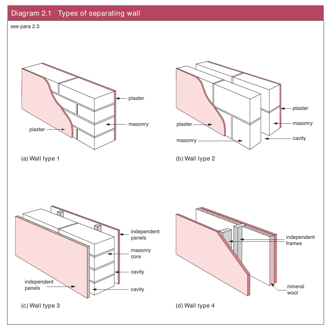
2.3The walls are grouped into four main types (see Diagram 2.1).
Wall type 1: Solid masonry
2.4The resistance to airborne sound depends mainly on the mass per unit area of the wall.
Wall type 2: Cavity masonry
2.5The resistance to airborne sound depends on the mass per unit area of the leaves and on the degree of isolation achieved. The isolation is affected by connections (such as wall ties and foundations) between the wall leaves and by the cavity width.
Wall type 3: Masonry between independent panels
2.6The resistance to airborne sound depends partly on the type and mass per unit area of the core, and partly on the isolation and mass per unit area of the independent panels.
Wall type 4: Framed walls with absorbent material
2.7The resistance to airborne sound depends on the mass per unit area of the leaves, the isolation of the frames, and the absorption in the cavity between the frames.
2.8Within each wall type the constructions are ranked, as far as possible, with constructions providing higher sound insulation given first.
Junctions between separating walls and other building elements
#Source page 27
Diagram 2.1 Types of separating wall
Junctions between separating walls and other building elements
2.9In order for the construction to be fully effective, care should be taken to correctly detail the junctions between the separating wall and other elements, such as floors, roofs, external walls and internal walls. Recommendations are also given for the construction of these elements, where it is necessary to control flanking transmission. Notes and diagrams explain the junction details for each of the separating wall types.
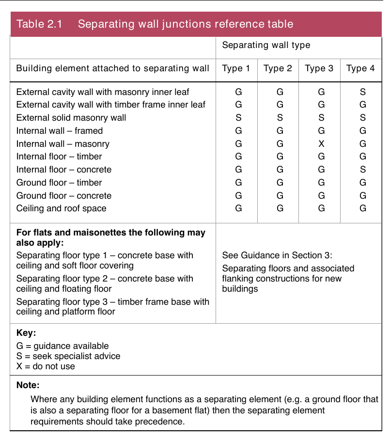
2.10Table 2.1 indicates the inclusion of guidance in this document on the junctions that may occur between each of the four separating wall types and various attached building elements.
Mass per unit area of walls
#Source page 28
Table 2.1 Separating wall junctions reference table
| Separating wall type | ||||
|---|---|---|---|---|
| Building element attached to separating wall | Type 1 | Type 2 | Type 3 | Type 4 |
| External cavity wall with masonry inner leaf | G | G | G | S |
| External cavity wall with timber frame inner leaf | G | G | G | G |
| External solid masonry wall | S | S | S | S |
| Internal wall – framed | G | G | G | G |
| Internal wall – masonry | G | G | X | G |
| Internal floor – timber | G | G | G | G |
| Internal floor – concrete | G | G | G | S |
| Ground floor – timber | G | G | G | G |
| Ground floor – concrete | G | G | G | G |
| Ceiling and roof space | G | G | G | G |
| For flats and maisonettes the following may also apply: Separating floor type 1 – concrete base with ceiling and soft floor covering Separating floor type 2 – concrete base with ceiling and floating floor Separating floor type 3 – timber frame base with ceiling and platform floor | See Guidance in Section 3: Separating floors and associated flanking constructions for new buildings | |||
| Key: G = guidance available S = seek specialist advice X = do not use | ||||
| Note: Where any building element functions as a separating element (e.g. a ground floor that is also a separating floor for a basement flat) then the separating element requirements should take precedence. |
Mass per unit area of walls
2.11The mass per unit area of a wall is expressed in kilograms per square metre (kg/m2). The method for calculating mass per unit area is given in Appendix A.
2.12The density of the materials used (and on which the mass per unit area of the wall depends) is expressed in kilograms per cubic metre (kg/m 3). When calculating the mass per unit area for bricks and blocks use the density at the standard moisture content from Section 3 of CIBSE Guide A (2006).
2.13The guidance describes constructions that use blocks without voids. For blocks with voids, seek advice from the manufacturer.
Plasterboard linings on separating and external masonry walls
2.14The guidance describes some constructions with only wet finishes. For dry finishes, seek advice from the manufacturer.
2.15Wherever plasterboard is recommended, or the finish is not specified, a drylining laminate of plasterboard with mineral wool may be used. For other drylining laminates, seek advice from the manufacturer.
Cavity widths in separating cavity masonry walls
#Source page 29
2.16Plasterboard linings should be fixed according to manufacturer's instructions.
Cavity widths in separating cavity masonry walls
2.17Recommended cavity widths are minimum values.
Wall ties in separating and external cavity masonry walls
2.18Suitable wall ties for use in masonry cavity walls are indicated in the guidance by reference to either tie type A or B.
Tie type A
2.19Connect the leaves of a cavity masonry wall only where necessary by wire type (butterfly) ties as described in BS EN 8451 and spaced as required for structural purposes, see BS 56283 which limits this tie type and spacing to cavity widths of 50 mm to 75 mm with a minimum masonry leaf thickness of 90 mm. Alternatively, use wall ties with an appropriate measured dynamic stiffness for the cavity width. The specification for wall ties of dynamic stiffness, k Xmm in MN/m with a cavity width of X mm and n ties/m2 is n.kXmm<4.8 MN/m3.
Tie type B (for use only in external masonry cavity walls where tie type A does not satisfy the requirements of Part D: Structure, of the Building Regulations).
2.20Connect the leaves of a cavity masonry wall only where necessary by wire type (doubletriangle) ties as described in BS EN 8451 and spaced as required for structural purposes, see BS 56283 which limits this tie type and spacing to cavity widths of 50 mm to 75 mm with a minimum masonry leaf thickness of 90 mm. Alternatively, use wall ties with an appropriate measured dynamic stiffness for the cavity width. The specification for wall ties of dynamic stiffness, k Xmm in MN/m with a cavity width of X mm and n ties/m2 is n.kXmm<113 MN/m3.
Note – In external cavity masonry walls, tie type B may decrease the airborne sound insulation due to flanking transmission via the external wall leaf compared to tie type A.
2.21Measurements of the wall tie dynamic stiffness, k Xmm, should be carried out according to BRE Information Paper, IP 3/01.
2.22The number of ties per square metre, n, is calculated from the horizontal and vertical tie spacing distances, Sx and Sy in metres using n = 1 / (Sx.Sy). Example: for horizontal and vertical tie spacing distances of 0.9 m and
0.45m, n is 2.5 ties/m2.
2.23If k Xmm is not available for the required cavity width, it is acceptable to use available k Xmm data for X mm values less than the required cavity width to calculate n.k Xmm.
Corridor walls and doors
#Source page 30
2.24The separating walls described in this section should be used between corridors and flats and maisonettes, in order to control flanking transmission and to provide the required sound insulation. However, it is likely that the sound insulation of the separating wall will be reduced by the presence of a door.
2.25Ensure that any door in a separating wall has good perimeter sealing (including the threshold where practical) and a minimum mass per unit area of 25 kg/m2 or a minimum sound reduction index of 29 dB Rw (measured according to BS EN ISO 1403 and rated according to BS EN ISO 7171.
2.26Noisy parts of the building should preferably have a lobby, double door or high performance doorset to contain the noise. Where this is not possible, nearby flats and maisonettes should have a similar level of protection.
Services
2.27The design of building services, their position in the building structure relative to habitable rooms and kitchens should be considered at an early stage in the design process as services noise and structure borne sound are the most common cause of complaint.
The most effective approach to structure borne sound is to decouple service installations and equipment from separating walls and separating floors through the use of, e.g. resilient mountings.
Refuse chutes
2.28A wall separating a habitable room or kitchen and a refuse chute should have a mass per unit area (including any finishes) of at least 1320 kg/m2. A wall separating a nonhabitable room from a refuse chute should have a mass per unit area (including any finishes) of at least 220 kg/m2.
WALL TYPE 1 – SOLID MASONRY
#Source page 31
2.29The resistance to airborne sound depends mainly on the mass per unit area of the wall.
Constructions
2.30Three wall type 1 constructions (types 1.1, 1.2, and 1.3) are described in this guidance.
2.31Details of how junctions should be made to limit flanking transmission are also described in this guidance.
2.32Points to watch –
Do
(a)Do fill and seal all masonry joints with mortar.
(b)Do lay bricks frog up to achieve the required mass per unit area and avoid air paths.
(c)Do use bricks/blocks that extend to the full thickness of the wall.
(d)Do ensure that an external cavity wall is stopped with a cavity stop at the junction with a separating wall, unless the cavity is fully filled with mineral wool or expanded polystyrene beads (seek manufacturer's advice for other suitable materials).
(e)Do control flanking transmission from walls and floors connected to the separating wall as described in the guidance on junctions.
(f)Do stagger the position of electrical sockets and switches on opposite sides of the separating wall.
(g)Do ensure that flue blocks will not adversely affect the sound insulation and that a suitable finish is used over the flue blocks (see BS EN 1858 and seek manufacturer's advice).
Do not
(h)Do not try and convert a cavity separating wall to a type 1 (solid masonry) separating wall by inserting mortar or concrete into the cavity between the two leaves.
(i)Do not use deep sockets and chases in the separating wall, and do not place electrical sockets or switches back to back.
(j)Do not create a junction between a solid wall type 1 and a cavity wall type 2 in which the cavity wall is bridged by the solid wall.
Wall type 1.1
#Source page 32
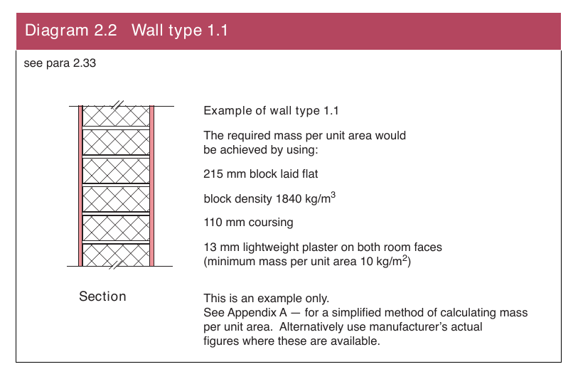
2.33Dense aggregate concrete block, plaster on both room faces (see Diagram 2.2) – minimum mass per unit area including plaster 415 kg/m2;
13mm plaster on both room faces; use blocks that are laid flat to the full thickness of the wall.
Diagram 2.2 Wall type 1.1
Wall type 1.2
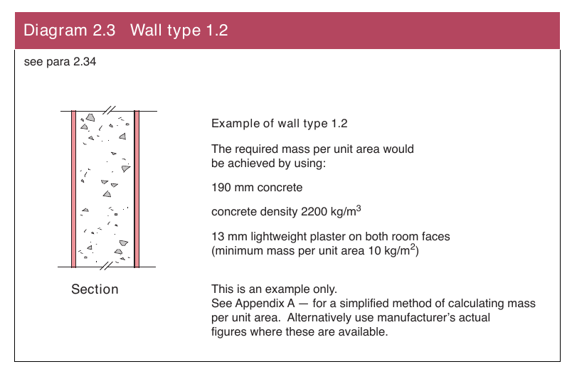
2.34Dense aggregate concrete cast insitu, plaster on both room faces (see Diagram 2.3) – minimum mass per unit area including plaster 415 kg/m2; plaster on both room faces.
Diagram 2.3 Wall type 1.2
Wall type 1.3
#Source page 33
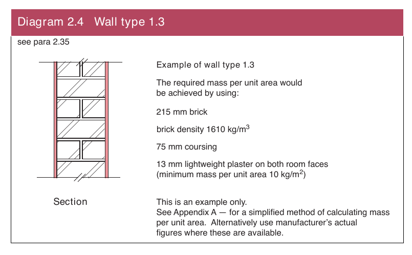
2.35Brick, plaster on both room faces (see Diagram 2.4) – minimum mass per unit area including plaster 375 kg/m2; 13 mm plaster on both room faces; bricks to be laid frog up, coursed with headers.
Diagram 2.4 Wall type 1.3
Junction requirements for wall type 1
Junctions with an external cavity wall with masonry inner leaf
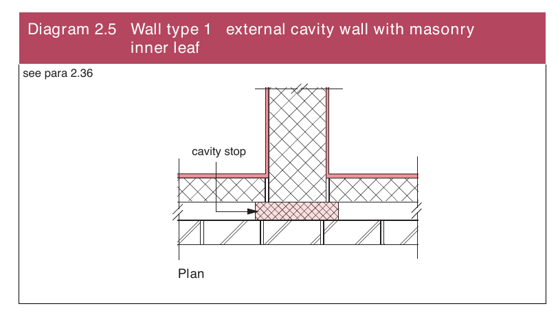
2.36Where the external wall is a cavity wall –
(a)the outer leaf of the wall may be of any construction; and
(b)the cavity should be closed with a cavity stop (see Diagram 2.5) unless the cavity is fully filled with mineral wool or expanded polystyrene beads (seek manufacturer's advice for other suitable materials).
Diagram 2.5 Wall type 1 external cavity wall with masonry
Page 34
#Source page 34
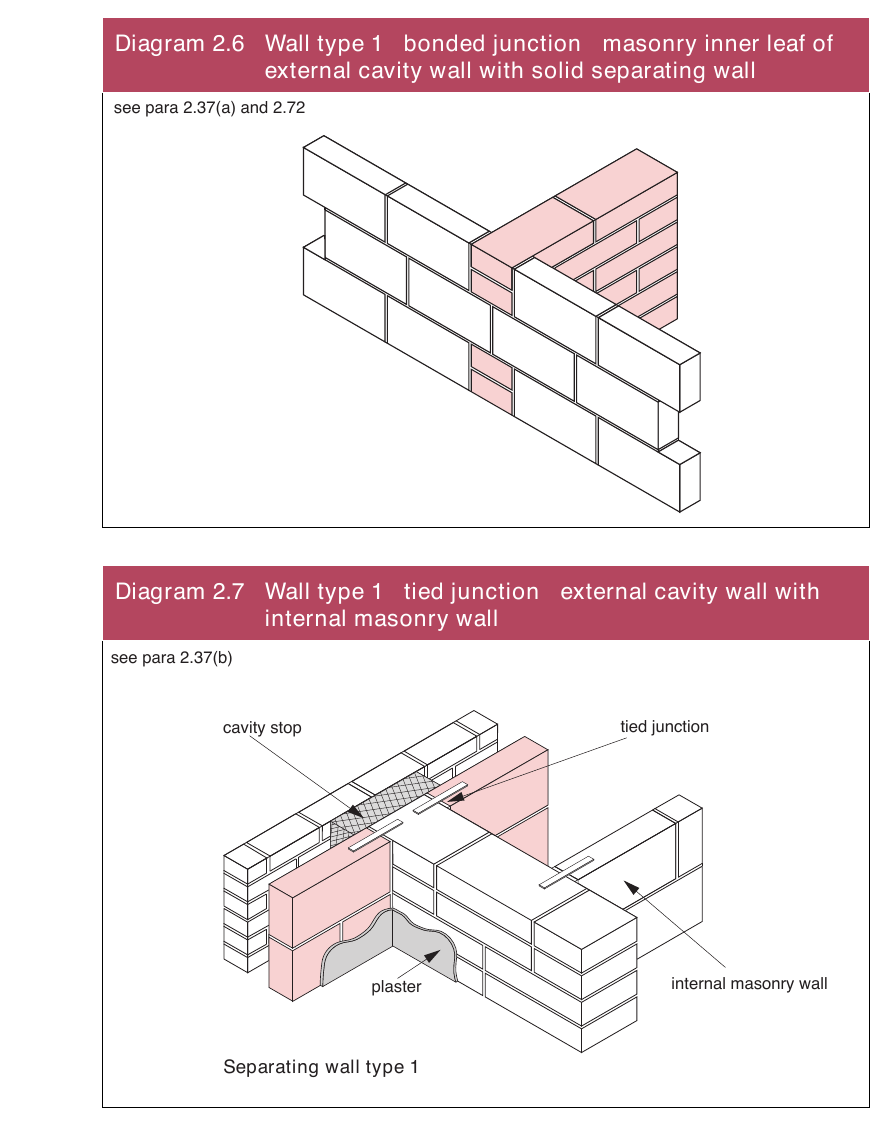
2.37The separating wall should be joined to the inner leaf of the external cavity wall by one of the following methods –
(a)Bonded. The separating wall should be bonded to the external wall in such a way that the separating wall contributes at least 50% of the bond at the junction (see Diagram 2.6).
(b)Tied. The external wall should abut the separating wall and be tied to it (see Diagram 2.7).
Diagram 2.6 Wall type 1 bonded junction masonry inner leaf of
Page 35
#Source page 35
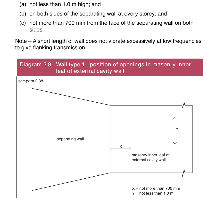
2.38The masonry inner leaf should have a mass per unit area of at least 120 kg/m2 excluding finish. However, there is no minimum mass requirement where there are openings in the external wall (see Diagram 2.8) that are –
(a)not less than 1.0 m high; and
(b)on both sides of the separating wall at every storey; and
(c)not more than 700 mm from the face of the separating wall on both sides.
Note – A short length of wall does not vibrate excessively at low frequencies to give flanking transmission.
2.39Where there is also a separating floor then the requirement for a minimum mass per unit area of 120 kg/m2 excluding finish should always apply, irrespective of the presence or absence of openings.
Junctions with an external cavity wall with timber frame inner leaf
#Source page 36
2.40Where the external wall is a cavity wall –
(a)the outer leaf of the wall may be of any construction; and
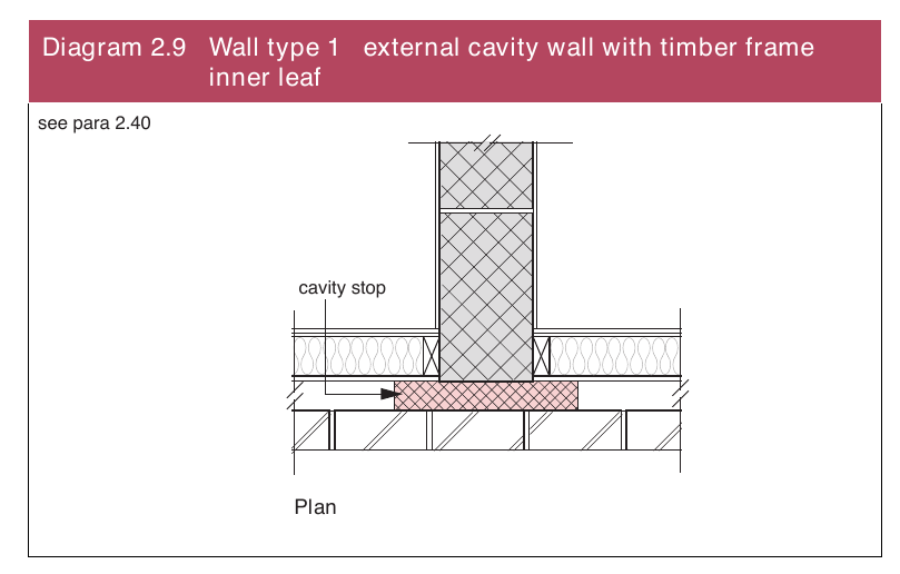
(b)the cavity should be closed with a cavity stop (see Diagram 2.9).
Diagram 2.9 Wall type 1 external cavity wall with timber frame
2.41Where the inner leaf of an external cavity wall is of framed construction, the framed inner leaf should –
(a)abut the separating wall; and
(b)be tied to it with ties at not more than 300 mm centres vertically.
The wall finish of the framed inner leaf of the external wall should be –
(c)one layer of plasterboard; or
(d)two layers of plasterboard with staggered joints where there is a separating floor; and
(e)each sheet of plasterboard to be of minimum mass per unit area 10 kg/m2; and
(f)all joints should be sealed with tape or caulked with sealant.
Junctions with an external solid masonry wall
2.42Seek specialist advice.
Junctions with internal framed walls
2.43There are no restrictions on internal framed walls meeting a type 1 separating wall.
Junctions with internal masonry walls
2.44Internal masonry walls that abut a type 1 separating wall should have a mass per unit area of at least 120 kg/m2 excluding finish.
Junctions with internal timber floors
#Source page 37
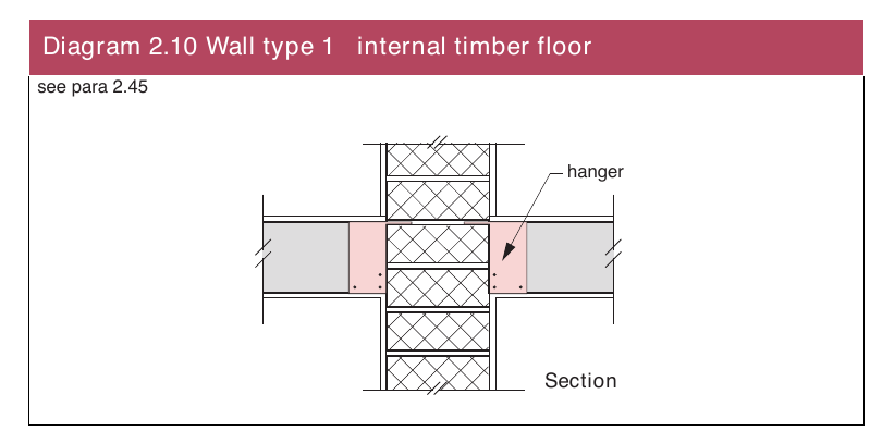
2.45If the floor joists are to be supported on a type 1 separating wall then they should be supported on hangers and should not be built in (see Diagram 2.10).
Diagram 2.10 Wall type 1 internal timber floor
Junctions with internal concrete floors
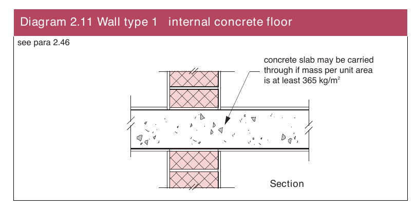
2.46An internal concrete floor slab may only be carried through a type 1 separating wall if the floor base has a mass per unit area of at least 365 kg/m2 (see Diagram 2.11).
Diagram 2.11 Wall type 1 internal concrete floor
2.47Internal hollowcore concrete plank floors and concrete beams with infilling block floors should not be continuous through a type 1 separating wall.
2.48For internal floors of concrete beams with infilling blocks, beams built in to the separating wall should be avoided unless the blocks in the floor fill the space between the beams where they penetrate the wall.
Junctions with timber ground floors
2.49If the floor joists are to be supported on a type 1 separating wall then they should be supported on hangers and should not be built in.
Junctions with concrete ground floors
#Source page 38
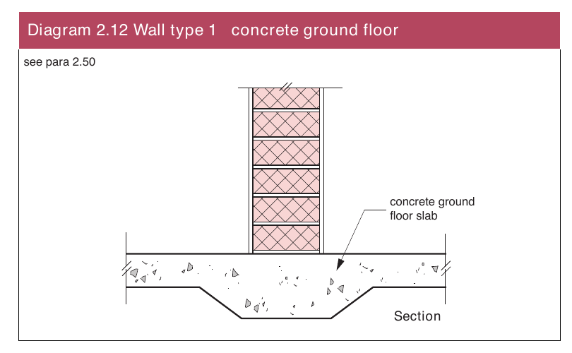
2.50The ground floor may be a solid slab, laid on the ground, or a suspended concrete floor. A concrete slab floor on the ground may be continuous under a type 1 separating wall (see Diagram 2.12).
Diagram 2.12 Wall type 1 concrete ground floor
2.51A suspended concrete floor may only pass under a type 1 separating wall if the floor has a mass of at least 365 kg/m2.
2.52Hollow core concrete plank and concrete beams with infilling block floors should not be continuous under a type 1 separating wall.
Junctions with ceiling and roof
2.53Where a type 1 separating wall is used it should be continuous to the underside of the roof.
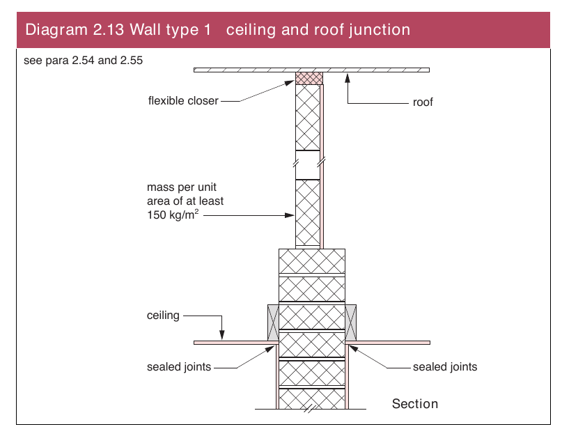
2.54The junction between the separating wall and the roof should be filled with a flexible closer (see Diagram 2.13).
2.55Where the roof or loft space is not a habitable room and there is a ceiling with a minimum mass per unit area of 10 kg/m2 with sealed joints, then the mass per unit area of the separating wall above the ceiling may be reduced to 150 kg/m2 (see Diagram 2.13).
Junctions with separating floors
#Source page 39
Diagram 2.13 Wall type 1 ceiling and roof junction
2.56If lightweight aggregate blocks of density less than 1200 kg/m3 are used above ceiling level, then one side should be sealed with cement paint or plaster skim.
2.57Where there is an external cavity wall, the cavity should be closed at eaves level with a cavity stop e.g. mineral wool (see Diagram 2.14).
Diagram 2.14 External cavity wall at eaves level
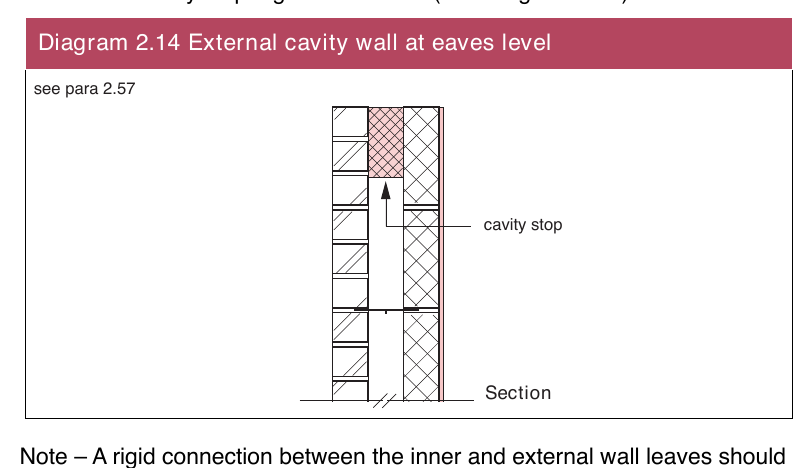
Note – A rigid connection between the inner and external wall leaves should be avoided. If a rigid material is used, then it should only be rigidly bonded to one leaf. See BRE BR 262, Thermal Insulation: avoiding risks, Section 2.3.
Junctions with separating floors
2.58There are important details in Section 3 concerning junctions between wall type 1 and separating floors.
WALL TYPE 2 – CAVITY MASONRY
#Source page 40
2.59The resistance to airborne sound depends on the mass per unit area of the leaves and on the degree of isolation achieved. The isolation is affected by connections (such as wall ties and foundations) between the wall leaves and by the cavity width.
Air movement in a cavity masonry separating wall can be a source of significant heat loss. This is known as the party wall thermal bypass and is addressed by Part F of the Building Regulations. Any measures taken for compliance with Part F, such as filling and sealing of the cavity, should not conflict with the requirements of Part G.
Constructions
2.60Four wall type 2 constructions (types 2.1, 2.2, 2.3 and 2.4) are described in this guidance.
2.61Two of these wall constructions (types 2.3 and 2.4) are only suitable when a step in elevation and/or a stagger in plan is incorporated at the separating wall. The step/stagger should be at least 300 mm.
2.62Details of how junctions should be made to limit flanking transmission are also described in this guidance.
2.63Points to watch –
Do
(a)Do fill and seal all masonry joints with mortar.
(b)Do keep the cavity leaves separate below ground floor level.
(c)Do ensure that any external cavity wall is stopped with a cavity stop at the junction with the separating wall, unless the cavity is fully filled with mineral wool (seek manufacturer's advice for other suitable materials).
(d)Do control flanking transmission from walls and floors connected to the separating wall as described in the guidance on junctions.
(e)Do stagger the position of electrical sockets and switches on opposite sides of the separating wall.
(f)Do ensure that flue blocks will not adversely affect the sound insulation and that a suitable finish is used over the flue blocks (see BS EN 1858 and seek manufacturer's advice).
Do not
(g)Do not try and convert a cavity separating wall to a type 1 (solid masonry) separating wall by inserting mortar or concrete into the cavity between the two leaves.
(h)Do not change to a solid wall construction in the roof space as a rigid connection between the leaves will reduce wall performance.
(i)Do not build cavity walls off a continuous solid concrete slab floor.
(j)Do not use deep sockets and chases in the separating wall, do not place them back to back.
Wall ties in separating cavity masonry walls
#Source page 41
2.64The wall ties used to connect the leaves of a cavity masonry wall should be tie type A.
Cavity widths in separating cavity masonry walls
2.65Recommended cavity widths are minimum values.
Blocks with voids
2.66The guidance describes constructions that use blocks without voids. For blocks with voids, seek advice from the manufacturer.
Wall type 2.1
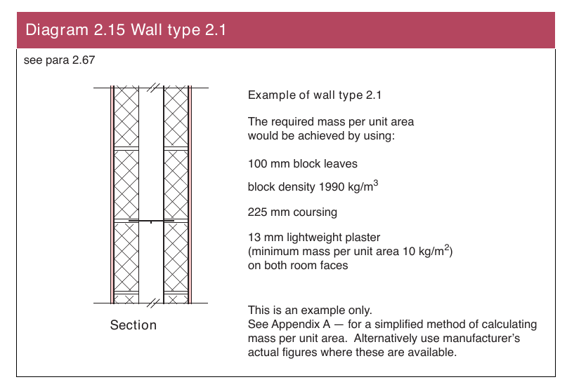
2.67Two leaves of dense aggregate concrete block with 50 mm cavity, plaster on both room faces (see Diagram 2.15) – minimum mass per unit area including plaster 415 kg/m2;
minimum cavity width of 50 mm; 13 mm plaster on both room faces.
Diagram 2.15 Wall type 2.1
Wall type 2.2
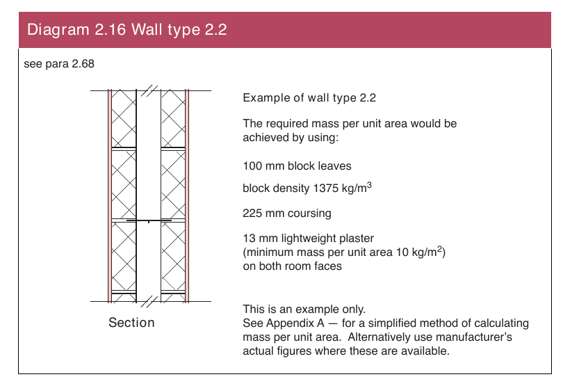
2.68Two leaves of lightweight aggregate block with 75 mm cavity, plaster on both room faces (see Diagram 2.16) – minimum mass per unit area including plaster 300 kg/m2;
minimum cavity width of 75 mm; 13 mm plaster on both room faces.
Additional construction – wall type 2.3 should only be used where there is a step and/or stagger of at least 300 mm.
#Source page 42
Diagram 2.16 Wall type 2.2
Additional construction – wall type 2.3 should only be used where there is a step and/or stagger of at least 300 mm.
Wall type 2.3
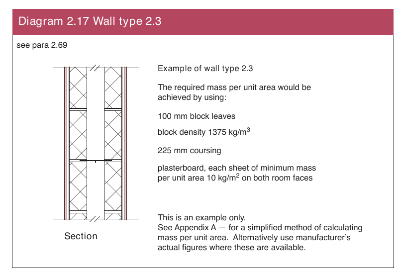
2.69Two leaves of lightweight aggregate block with 75 mm cavity and plasterboard on both room faces (see Diagram 2.17) – minimum mass per unit area including plasterboard 290 kg/m2; lightweight aggregate blocks should have a density in the range 1350 to 1600 kg/m3;
minimum cavity width of 75 mm; plasterboard, each sheet of minimum mass per unit area 10 kg/m2, on both room faces.
Diagram 2.17 Wall type 2.3
Additional construction – wall type 2.4 should only be used in constructions without separating floors and where there is a step and/or stagger of at least 300 mm
#Source page 43
Note 1 – The composition of the lightweight aggregate blocks contributes to the performance of this construction with a plasterboard finish. Using denser blocks may not give an equivalent performance.
Note 2 – Increasing the size of the step or stagger in the separating wall tends to improve the airborne sound insulation.
Additional construction – wall type 2.4 should only be used in constructions without separating floors and where there is a step and/or stagger of at least 300 mm
Wall type 2.4
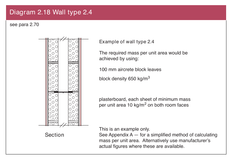
2.70Two leaves of aircrete block with 75 mm cavity and plasterboard or plaster on both room faces (see Diagram 2.18) – minimum mass per unit area including finish 150 kg/m2;
minimum cavity width of 75 mm;
plasterboard, each sheet of minimum mass per unit area 10 kg/m2, on both room faces; or
13mm plaster on both room faces.
Diagram 2.18 Wall type 2.4
Note – Increasing the size of the step or stagger in the separating wall tends to improve the airborne sound insulation.
Junction requirements for wall type 2
#Source page 44
Junctions with an external cavity wall with masonry inner leaf
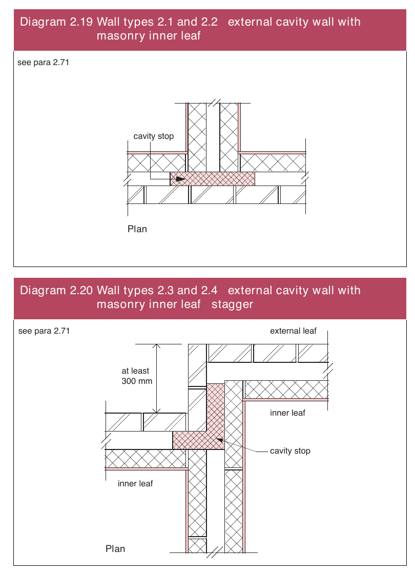
2.71Where the external wall is a cavity wall –
(a)the outer leaf of the wall may be of any construction; and
(b)the cavity should be closed with a cavity stop (for wall types 2.1 and
2.2see Diagram 2.19, for wall types 2.3 and 2.4 see Diagram 2.20) unless the cavity is fully filled with mineral wool or expanded polystyrene beads (seek manufacturer's advice for other suitable materials).
Diagram 2.19 Wall types 2.1 and 2.2 external cavity wall with
Junctions with an external cavity wall with timber frame inner leaf
#Source page 45
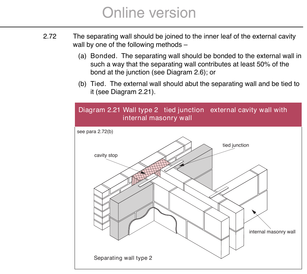
2.72The separating wall should be joined to the inner leaf of the external cavity wall by one of the following methods –
(a)Bonded. The separating wall should be bonded to the external wall in such a way that the separating wall contributes at least 50% of the bond at the junction (see Diagram 2.6); or
(b)Tied. The external wall should abut the separating wall and be tied to it (see Diagram 2.21).
2.73The masonry inner leaf should have a mass per unit area of at least 120 kg/m2 excluding finish. However, there is no minimum mass requirement where separating wall type 2.1, 2.3 or 2.4 is used.
2.74Where there is also a separating floor then the requirement for a minimum mass per unit area of 120 kg/m2 excluding finish should always apply, even when wall type 2.1, 2.3 or 2.4 is used.
Junctions with an external cavity wall with timber frame inner leaf
2.75Where the external wall is a cavity wall –
(a)the outer leaf of the wall may be of any construction; and
(b)the cavity should be closed with a cavity stop (see Diagram 2.22).
Junctions with an external solid masonry wall
#Source page 46
Diagram 2.22 Wall type 2 external cavity wall with timber frame
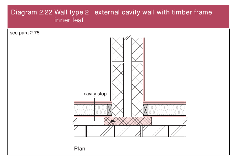
2.76Where the inner leaf of an external cavity wall is of framed construction, the framed inner leaf should –
(a)abut the separating wall; and
(b)be tied to it with ties at not more than 300 mm centres vertically.
The wall finish of the inner leaf of the external wall should be –
(c)one layer of plasterboard; or
(d)two layers of plasterboard with staggered joints where there is a separating floor; and
(e)each sheet of plasterboard to be of minimum mass per unit area 10 kg/m2; and
(f)all joints should be sealed with tape or caulked with sealant.
Junctions with an external solid masonry wall
2.77Seek specialist advice.
Junctions with internal framed walls
2.78There are no restrictions on internal framed walls meeting a type 2 separating wall.
Junctions with internal masonry walls
2.79Internal masonry walls that abut a type 2 separating wall should have a mass per unit area of at least 120 kg/m2 excluding finish.
2.80Where there is a separating floor, internal masonry walls should have a mass per unit area of at least 120 kg/m2 excluding finish.
2.81When there is no separating floor with separating wall type 2.3 or 2.4 there is no minimum mass per unit area for internal masonry walls.
Junctions with internal timber floors
#Source page 47
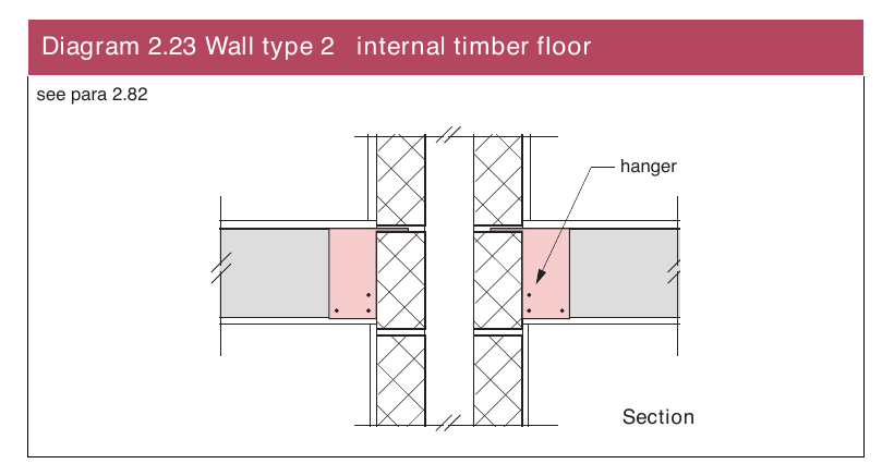
2.82If the floor joists are to be supported on the separating wall then they should be supported on hangers and should not be built in (see Diagram 2.23).
Diagram 2.23 Wall type 2 internal timber floor
Junctions with internal concrete floors
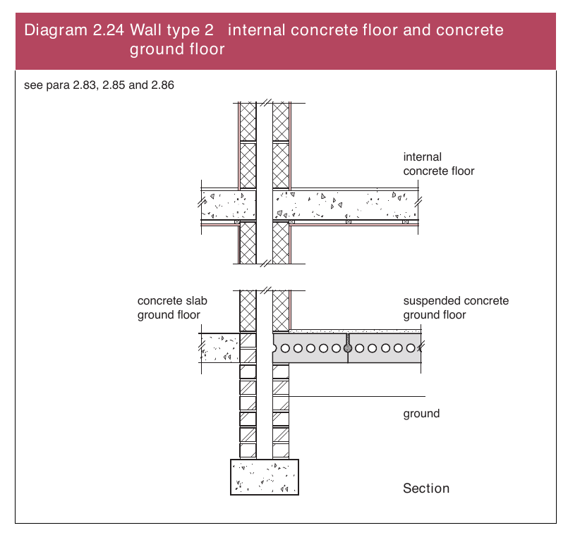
2.83Internal concrete floors should generally be built into a type 2 separating wall and carried through to the cavity face of the leaf. The cavity should not be bridged (see Diagram 2.24).
Diagram 2.24 Wall type 2 internal concrete floor and concrete
Junctions with timber ground floors
#Source page 48
2.84If the floor joists are to be supported on the separating wall then they should be supported on hangers and should not be built in.
Junctions with concrete ground floors
2.85The ground floor may be a solid slab, laid on the ground, or a suspended concrete floor. A concrete slab floor on the ground should not be continuous under a type 2 separating wall (see Diagram 2.24).
2.86A suspended concrete floor should not be continuous under a type 2 separating wall, and should be carried through to the cavity face of the leaf. The cavity should not be bridged (see Diagram 2.24).
Junctions with ceiling and roof space
2.87Where a type 2 separating wall is used it should be continuous to the underside of the roof.
2.88The junction between the separating wall and the roof should be closed with a flexible closer (see Diagram 2.25).
Diagram 2.25 Wall type 2 ceiling and roof junction
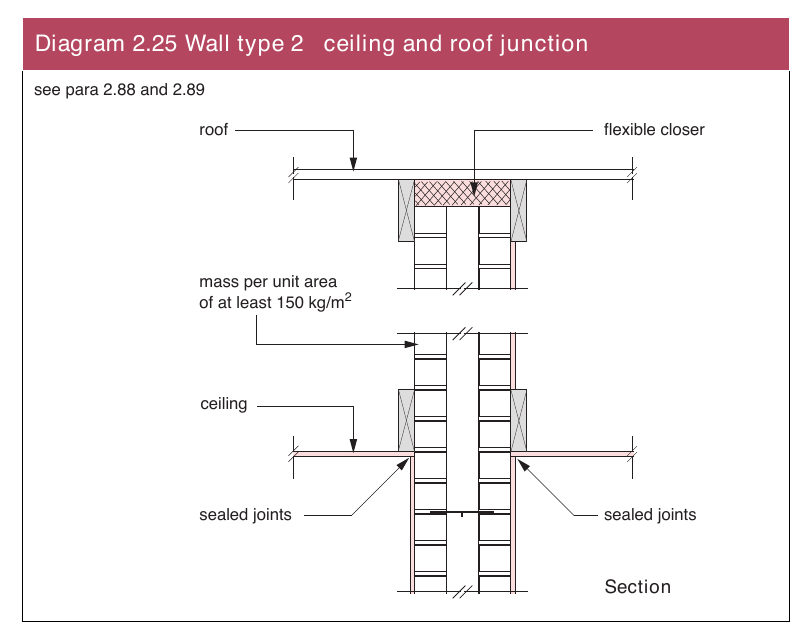
2.89Where the roof or loft space is not a habitable room and there is a ceiling with a minimum mass per unit area of 10 kg/m2 with sealed joints, then the mass per unit area of the separating wall above the ceiling may be reduced to 150 kg/m2, but it should still be a cavity wall (see Diagram 2.25).
2.90If lightweight aggregate blocks of density less than 1200 kg/m3 are used above ceiling level, then one side should be sealed with cement paint or plaster skim.
Junctions with separating floors
#Source page 49
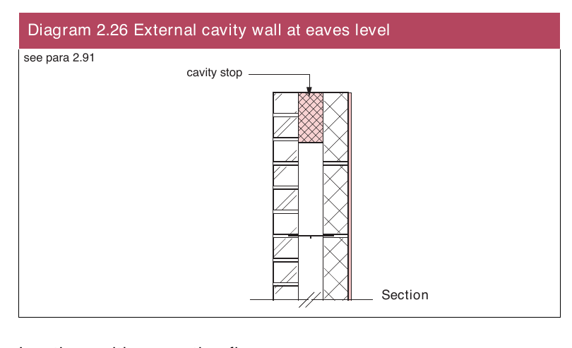
2.91Where there is an external cavity wall, the cavity should be closed at eaves level with a cavity stop e.g. mineral wool (see Diagram 2.26).
A rigid connection between the inner and external wall leaves should be avoided. If a rigid material is used, then it should only be rigidly bonded to one leaf.
Diagram 2.26 External cavity wall at eaves level
Junctions with separating floors
2.92There are important details in Section 3 concerning junctions between wall type 2 and separating floors.
WALL TYPE 3 – MASONRY BETWEEN INDEPENDENT PANELS
#Source page 50
2.93The resistance to airborne sound depends partly on the type and mass per unit area of the core, and partly on the isolation and mass per unit area of the independent panels.
Note – Wall type 3 can give high resistance to the transmission of both airborne sound and impact sound on the wall.
Constructions
2.94Three wall type 3 constructions (types 3.1, 3.2 and 3.3) are described in this guidance.
2.95The construction consists of either a solid or cavity masonry core wall with independent panels on both sides. These panels and any frame should not be in contact with the core wall.
2.96Details of how junctions should be made to limit flanking transmission are also described in this guidance.
2.97Points to watch –
Do
(a)Do fill and seal all masonry joints with mortar.
(b)Do control flanking transmission from walls and floors connected to the separating wall as described in the guidance on junctions.
(c)Do fix the panels or the supporting frames to the ceiling and floor only.
(d)Do tape and seal all joints.
(e)Do ensure that flue blocks will not adversely affect the sound insulation and that a suitable finish is used over the flue blocks (see BS EN 1858 and seek manufacturer's advice).
Do not
(f) Do not fix, tie or connect the free standing panels or the frame to the masonry core.
Wall ties in cavity masonry cores
2.98The wall ties used to connect the leaves of a cavity masonry core should be tie type A.
Cavity widths in separating cavity masonry cores
2.99Recommended cavity widths are minimum values.
Wall type 3.1
#Source page 51
Independent panels.
2.100These panels should meet the following specification – minimum mass per unit area of panel (excluding any supporting framework) 20 kg/m2; panels should consist of either –
(a)at least 2 layers of plasterboard with staggered joints; or
(b)a composite panel consisting of 2 sheets of plasterboard separated by a cellular core;
if the panels are not supported on a frame they should be at least 35 mm from the masonry core; or if the panels are supported on a frame there should be a gap of at least 10 mm between the frame and the masonry core.
Wall type 3.1
2.101Solid masonry core (dense aggregate concrete block), independent panels on both room faces (see Diagram 2.27 and 2.28) – minimum mass per unit area of core 300 kg/m2;
minimum core width is determined by structural requirements; independent panels on both room faces.
Diagram 2.27 Wall type 3.1 with independent composite panels
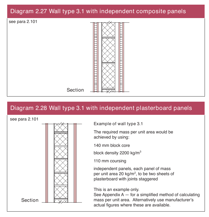
Wall type 3.2
#Source page 52
2.102Solid masonry core (lightweight concrete block), independent panels on both room faces (see Diagram 2.29) – minimum mass per unit area of core 150 kg/m2;
minimum core width is determined by structural requirements ; independent panels on both room faces.
Diagram 2.29 Wall type 3.2 with independent composite panels
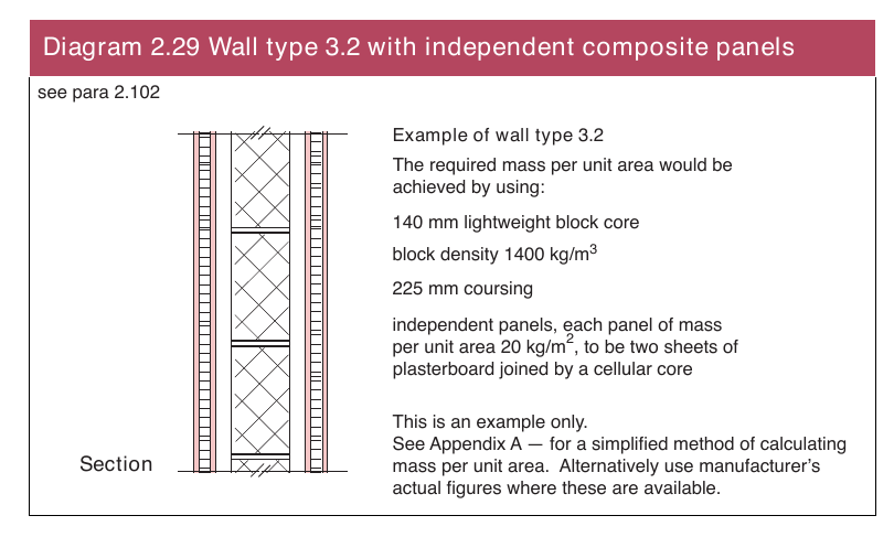
Wall type 3.3
2.103Cavity masonry core (brickwork or blockwork), 50 mm cavity, independent panels on both room faces (see Diagram 2.30) – the core can be of any mass per unit area; minimum cavity width of 50 mm;
minimum core width is determined by structural requirements; independent panels on both room faces.
Diagram 2.30 Wall type 3.3 with independent composite panels
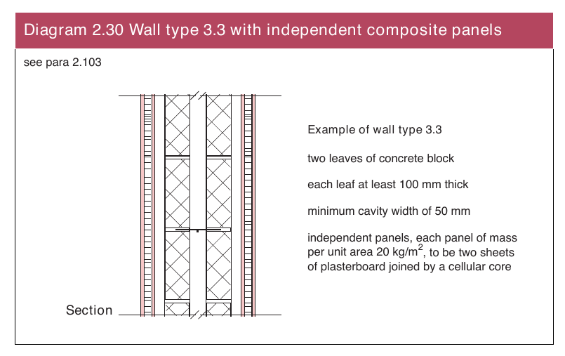
Junction requirements for wall type 3
#Source page 53
Junctions with an external cavity wall with masonry inner leaf
2.104Where the external wall is a cavity wall –
(a)the outer leaf of the wall may be of any construction; and
(b)the cavity should be closed with a cavity stop (see Diagram 2.31) unless the cavity is fully filled with mineral wool or expanded polystyrene beads (seek manufacturer's advice for other suitable materials).
Diagram 2.31 Wall type 3 external cavity wall with masonry inner
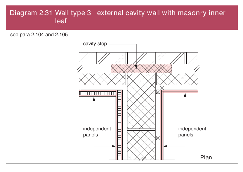
2.105Where the inner leaf of an external cavity wall is masonry –
(a)the inner leaf of the external wall should be bonded or tied to the masonry core; and
(b)the inner leaf of the external wall should be lined with independent panels in the same manner as the separating walls (see Diagram 2.31).
2.106Where there is a separating floor the masonry inner leaf of the external wall should have a minimum mass per unit area of at least 120 kg/m2 excluding finish.
2.107Where there is no separating floor and the masonry inner leaf of the external wall is lined with independent panels in the same manner as the separating walls, there is no minimum mass requirement on the masonry inner leaf.
2.108Where there is no separating floor with separating wall type 3.1 or 3.3, and the masonry inner leaf of the external wall has a mass of at least 120 kg/m2 excluding finish, then the inner leaf of the external wall may be finished with plaster or plasterboard of minimum mass per unit area 10 kg/m2.
Junctions with an external cavity wall with timber frame inner leaf
#Source page 54
2.109Seek specialist advice.
Junctions with an external solid masonry wall
2.110Seek specialist advice.
Junctions with internal framed walls
2.111Loadbearing framed internal walls should be fixed to the masonry core through a continuous pad of mineral wool (see Diagram 2.32).
Diagram 2.32 Wall type 3 external cavity wall with internal timber
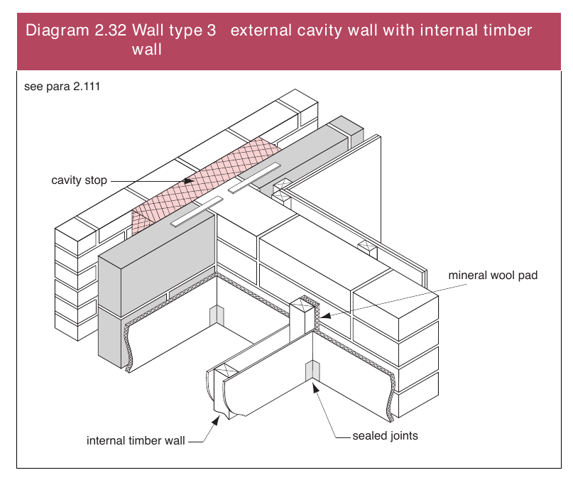
2.112Non loadbearing internal walls should be butted to the independent panels.
2.113All joints between internal walls and panels should be sealed with tape or caulked with sealant.
Junctions with internal masonry walls
2.114Internal walls that abut a type 3 separating wall should not be of masonry construction.
Junctions with internal timber floors
#Source page 55
2.115If the floor joists are to be supported on the separating wall then they should be supported on hangers and should not be built in (see Diagram 2.33).
Diagram 2.33 Wall type 3 internal timber floor
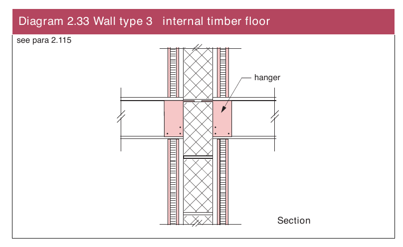
2.116Spaces between the floor joists should be sealed with full depth timber blocking. Any voids to be filled with flexible caulking.
Junctions with internal concrete floors
Wall types 3.1 and 3.2 (solid masonry core)
2.117An internal concrete floor slab may only be carried through a solid masonry core if the floor base has a mass per unit area of at least 365 kg/m2 (see Diagram 2.34).
Diagram 2.34 Wall types 3.1 and 3.2 internal concrete floor
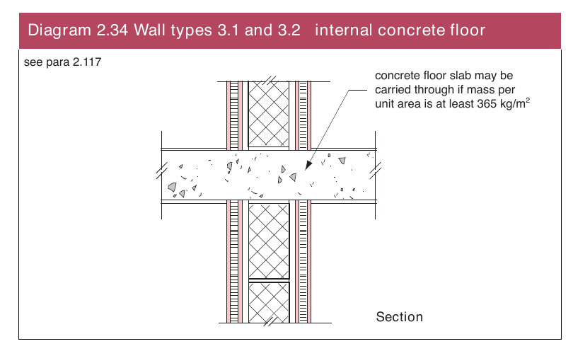
Wall type 3.3 (cavity masonry core)
#Source page 56
2.118Internal concrete floors should generally be built into a cavity masonry core and carried through to the cavity face of the leaf. The cavity should not be bridged.
Junctions with timber ground floors
2.119If the floor joists are to be supported on the separating wall then they should be supported on hangers and should not be built in.
2.120Spaces between the floor joists should be sealed with full depth timber blocking. Any voids to be filled with flexible caulking.
Junctions with concrete ground floors
2.121The ground floor may be a solid slab, laid on the ground, or a suspended concrete floor.
Wall type 3.1 and 3.2 (solid masonry core)
2.122A concrete slab floor on the ground may be continuous under the solid masonry core of a type 3.1 or 3.2 separating wall.
2.123A suspended concrete floor may only pass under the solid masonry core of a type 3.1 or 3.2 separating wall if the floor has a mass per unit area of at least 365 kg/m2.
2.124Hollow core concrete plank and concrete beams with infilling block floors should not be continuous under the solid masonry core of a type 3.1 or 3.2 separating wall.
Wall type 3.3 (cavity masonry core)
2.125A concrete slab floor on the ground should not be continuous under the cavity masonry core of a type 3.3 separating wall.
2.126A suspended concrete floor should not be continuous under the cavity masonry core of a type 3.3 separating wall and should be carried through to the cavity face of the leaf. The cavity should not be bridged.
Junctions with ceiling and roof space
#Source page 57
2.127The masonry core should be continuous to the underside of the roof.
2.128The junction between the separating wall and the roof should be filled with a flexible closer (see Diagram 2.35).
Diagram 2.35 Wall types 3.1 and 3.2 ceiling and roof junction
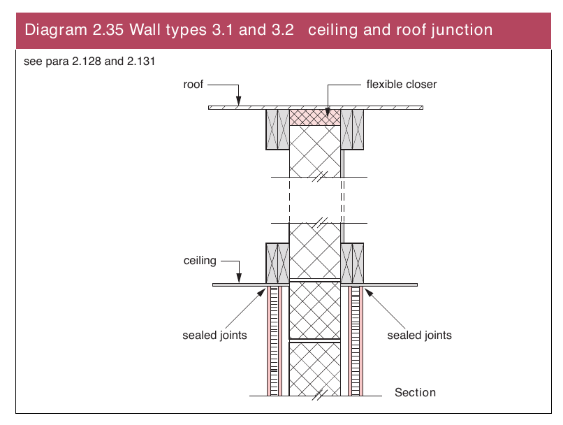
2.129The junction between the ceiling and independent panels should be sealed with tape or caulked with sealant.
2.130Where there is an external cavity wall, the cavity should be closed at eaves level with a cavity stop e.g. mineral wool (see Diagram 2.36).
Diagram 2.36 External cavity wall at eaves level
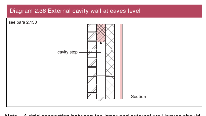
Note – A rigid connection between the inner and external wall leaves should be avoided. If a rigid material is used, then it should only be rigidly bonded to one leaf.
Wall types 3.1 and 3.2 (solid masonry core)
#Source page 58
2.131Where the roof or loft space is not a habitable room and there is a ceiling with a minimum mass per unit area of 10 kg/m2 and with sealed joints, the independent panels may be omitted in the roof space and the mass per unit area of the separating wall above the ceiling may be a minimum of 150 kg/m2 (see Diagram 2.35).
2.132If lightweight aggregate blocks of density less than 1200 kg/m3 are used above ceiling level, then one side should be sealed with cement paint or plaster skim.
Wall type 3.3 (cavity masonry core)
2.133Where the roof or loft space is not a habitable room and there is a ceiling with a minimum mass per unit area of 10 kg/m2 and with sealed joints, the independent panels may be omitted in the roof space but the cavity masonry core should be maintained to the underside of the roof.
Junctions with separating floors
2.134There are important details in Section 3 concerning junctions between wall type 3 and separating floors.
WALL TYPE 4 – FRAMED WALLS WITH ABSORBENT MATERIAL
#Source page 59
2.135
2.136
2.137
2.138
2.139
2.140
In this guidance only a timber framed wall is described. For steel framed walls, seek advice from the manufacturer.
The resistance to airborne sound depends on the mass per unit area of the leaves, the isolation of the frames, and the absorption in the cavity between the frames.
Constructions
The construction consists of timber frames, with plasterboard linings on room surfaces and with absorbent material between the frames.
One wall type 4 construction (type 4.1) is described in this guidance.
Details of how junctions should be made to limit flanking transmission are also described in this guidance.
Points to watch –
Do
(a)Do ensure that where cavity stops are needed in the cavity between frames they are either flexible or fixed to only one frame.
(b)Do stagger the position of electrical sockets and switches on opposite sides of the separating wall, and use a similar thickness of cladding behind the socket box.
(c)Do ensure that each layer of plasterboard is independently fixed to the stud frame.
(d)Do control flanking transmission from walls and floors connected to the separating wall as described in the guidance on junctions.
(e)Where it is necessary to connect the two leaves together for structural reasons, do use resilient connectors where possible.
Do not
(f)Where it is necessary to connect the two leaves together for structural reasons, do not use ties of greater cross section than 40 mm x 3 mm fixed to the studwork at or just below ceiling level and do not set them at closer than 1.2 m centres.
(g)Do not locate electrical sockets or switches back to back. A minimum edge to edge stagger of 150 mm is recommended. Do not chase plasterboard.
Wall type 4.1
#Source page 60
2.141Double leaf frames with absorbent material (see Diagram 2.37) – minimum distance between inside lining faces of 200 mm; plywood sheathing may be used in the cavity as necessary for structural reasons;
each lining to be two or more layers of plasterboard, each sheet of minimum mass per unit area 10 kg/m2, with staggered joints; absorbent material to be unfaced mineral wool batts or quilt (which may be wire reinforced), minimum density 10 kg/m3; minimum thickness of absorbent material –
(a)25 mm if suspended in the cavity between frames;
(b)50 mm if fixed to one frame; or
(c)25 mm per batt (or quilt) if one is fixed to each frame.
Diagram 2.37 Wall type 4.1
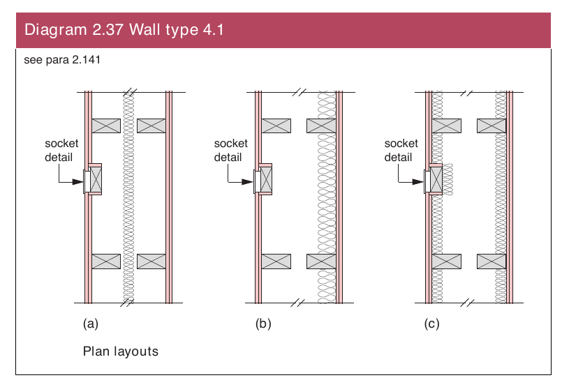
Note – A masonry core may be used where required for structural purposes, but the core should be connected to only one frame.
Junction requirements for wall type 4
#Source page 61
Junctions with an external cavity wall with masonry inner leaf
2.142Seek specialist advice.
Junctions with an external cavity wall with timber frame inner leaf
2.143Where the external wall is a cavity wall –
(a)the outer leaf of the wall may be of any construction; and
(b)the cavity should be closed between the ends of the separating wall and the outer leaf with a cavity stop (see Diagram 2.38).
Diagram 2.38 Wall type 4 external cavity wall with timber frame
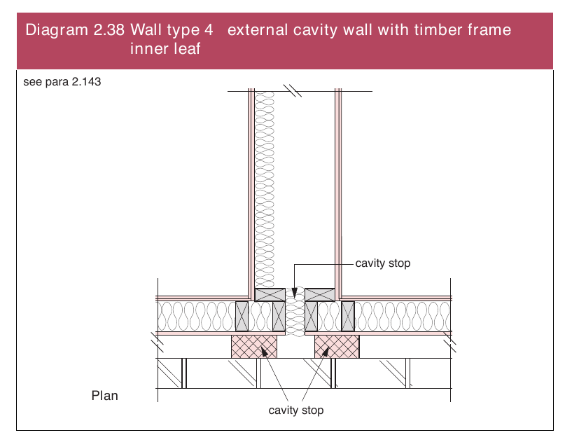
2.144The wall finish of the inner leaf of the external wall should be –
(a)one layer of plasterboard; or
(b)two layers of plasterboard with staggered joints where there is a separating floor; and
(c)each sheet of plasterboard of minimum mass per unit area 10 kg/m2; and
(d)all joints should be sealed with tape or caulked with sealant.
Junctions with an external solid masonry wall
2.145Seek specialist advice.
Junctions with internal framed walls
2.146There are no restrictions on internal framed walls meeting a type 4 separating wall.
Junctions with internal masonry walls
#Source page 62
2.147There are no restrictions on internal masonry walls meeting a type 4 separating wall.
Junctions with internal timber floors
2.148Block the air paths through the wall into the cavity by using solid timber blockings or a continuous ring beam or joists.
Junctions with internal concrete floors
2.149Seek specialist advice.
Junctions with timber ground floors
2.150Block the air paths through the wall into the cavity by using solid timber blockings or a continuous ring beam or joists.
Junctions with concrete ground floors
2.151The ground floor may be a solid slab, laid on the ground, or a suspended concrete floor. A concrete slab floor on the ground may be continuous under a type 4 separating wall. A suspended concrete floor may only pass under a wall type 4 if the floor has a mass per unit area of at least 365 kg/m2.
Junctions with ceiling and roof space
2.152The wall should preferably be continuous to the underside of the roof.
2.153The junction between the separating wall and the roof should be filled with a flexible closer.
2.154The junction between the ceiling and the wall linings should be sealed with tape or caulked with sealant.
Where the roof or loft space is not a habitable room and there is a ceiling with a minimum mass per unit area of 10 kg/m2 and with sealed joints, either –
(a)the linings on each frame may be reduced to two layers of plasterboard, with staggered joints, each sheet with a minimum mass per unit area of 10 kg/m2; or
(b)the cavity may be closed at ceiling level without connecting the two frames rigidly together and then one frame may be used in the roof space provided there is a lining of two layers of plasterboard, with staggered joints, each sheet with a minimum mass per unit area of 10 kg/m2, on both sides of the frame.
2.155Where there is an external wall cavity, the cavity should be closed at eaves level with a suitable material.
Junctions with separating floors
2.156There are important details in Section 3 concerning junctions between wall type 4 and separating floors.
General
#Source page 63
Section 3 Separating floors and associated flanking constructions for new buildings
General
3.1This Section gives examples of floor types which, if built correctly, should achieve the performance standards set out in Table 1a of the section entitled “Guidance Performance and introduction to provisions”. Precompletion testing will establish the compliance of the constructions built.
3.2The guidance in this section is not exhaustive and other designs, materials or products may be used to achieve the performance standards set out in Table 1a of the section entitled “Guidance Performance and introduction to provisions”. Advice should be sought from the manufacturer or other appropriate source.
3.3The floors are grouped into three main types (see Diagram 3.1).
Diagram 3.1 Types of separating floor
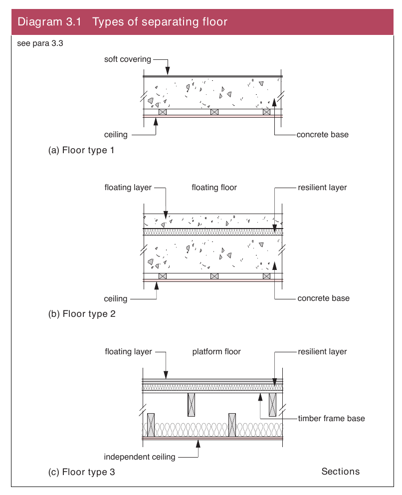
Junctions between separating floors and other building elements
#Source page 64
Floor type 1
3.4Concrete base with ceiling and soft floor covering
The resistance to airborne sound depends mainly on the mass per unit area of the concrete base and partly on the mass per unit area of the ceiling. The soft floor covering (see para 3.28) reduces impact sound at source.
Floor type 2
3.5Concrete base with ceiling and floating floor
The resistance to airborne and impact sound depends on the mass per unit area of the concrete base, as well as the mass per unit area and isolation of the floating layer and the ceiling. The floating floor reduces impact sound at source.
Floor type 2
3.6Floating floor
Floor type 2 requires one of the floating floors described in this section. The description of floor type 2 contains a suffix (a), (b) or (c) which refers to the floating floor used.
Floor type 3
3.7Timber frame base with ceiling and platform floor
The resistance to airborne and impact sound depends on the structural floor base and the isolation of the platform floor and the ceiling. The platform floor reduces impact sound at source.
Ceiling treatment
3.8Each floor type requires one of the ceiling treatments described in this section. The description of each floor type contains a suffix A, B or C that refers to the ceiling treatment used.
3.9Within each floor type the constructions are ranked, as far as possible, with constructions providing better sound insulation given first.
Junctions between separating floors and other building elements
3.10In order for the floor construction to be fully effective, care should be taken to correctly detail the junctions between the separating floor and other elements such as external walls, separating walls and floor penetrations. Recommendations are also given for the construction of these other elements where it is necessary to control flanking transmission. Notes and diagrams explain the junction details for each of the separating floor types.
3.11Table 3.1 indicates the inclusion of guidance in this document on the junctions that may occur between each of the separating floor types and various attached building elements.
Beam and block floors
#Source page 65
| Table 3.1 Separating floor junctions reference table | |||
|---|---|---|---|
| Separating floor type | |||
| Building element attached to separating wall | Type 1 | Type 2 | Type 3 |
| External cavity wall with masonry inner leaf External cavity wall with timber frame inner leaf External solid masonry wall Internal wall – framed Internal wall – masonry | G G S G G | G G S G G | G G S G S |
| Floor penetrations | G | G | G |
| For flats and maisonettes the following may also apply: Separating wall type 1 – solid masonry Separating wall type 2 – cavity masonry Separating wall type 3 – masonry between independent panels Separating wall type 4 – framed wall with absorbent material | G G G S | G G G S | G G G G |
| Key: G = guidance available S = seek specialist advice | |||
| Note: Where any building element functions as a separating element (e.g. a ground floor that is also a separating floor for a basement flat) then the separating element requirements should take precedence. |
Beam and block floors
3.12For beam and block separating floors, seek advice from the manufacturer.
Mass per unit area of floors
3.13The mass per unit area of a floor is expressed in kilograms per square metre (kg/m2). The mass per unit area of floors should be obtained from manufacturer's data or calculated using the method shown in Appendix A.
3.14The density of the materials used (and on which the mass per unit area of the floor depends) is expressed in kilograms per cubic metre (kg/m3).
3.15Where appropriate, the mass per unit area of a bonded screed may be included in the calculation of the mass per unit area of the floor.
3.16The mass per unit area of a floating screed should not be included in the calculation of the mass per unit area of the floor.
Ceiling treatments
#Source page 66
3.17Each floor type should use one of the following three ceiling treatments, A, B or C, (see Diagram 3.2).
Diagram 3.2 Ceiling treatments A, B and C
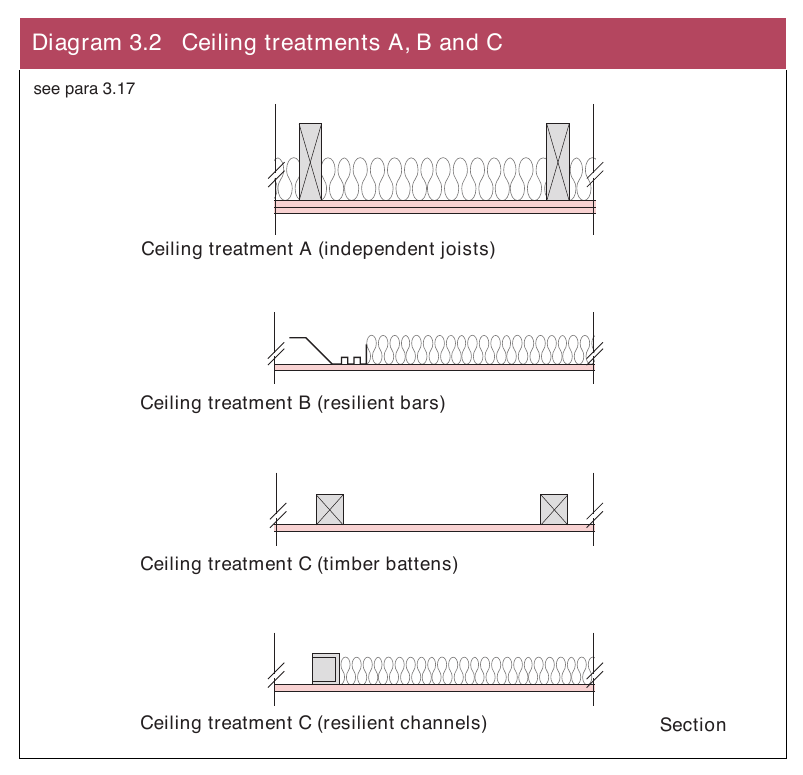
3.18The ceiling treatments are ranked, in order of sound insulation performance from A to C, with constructions providing higher sound insulation given first.
Note – Use of a better performing ceiling than that described in the guidance should improve the sound insulation of the floor provided there is no significant flanking transmission.
Ceiling treatment A
3.19Independent ceiling with absorbent material –
Ceiling treatment A should meet the following specification –
(a)at least 2 layers of plasterboard with staggered joints;
(b)minimum total mass per unit area of plasterboard 20 kg/m2; and
(c)an absorbent layer of mineral wool (minimum thickness 100 mm, minimum density 10 kg/m3) laid in the cavity formed above the ceiling.
The ceiling should be supported by one of the following methods –
(d)Floor types 1, 2 and 3. Use independent joists fixed only to the surrounding walls. A clearance of at least 100 mm should be left between the top of the plasterboard forming the ceiling and the underside of the base floor.
Page 67
#Source page 67
(e)Floor type 3. Use independent joists fixed to the surrounding walls with additional support provided by resilient hangers attached directly to the floor. A clearance of at least 100 mm should be left between the top of the ceiling joists and the underside of the base floor.
3.20Points to watch –
Do
(a) Do seal the perimeter of the independent ceiling with tape or sealant.
Do not
(b)Do not create a rigid or direct connection between the independent ceiling and the floor base.
(c)Do not install recessed light fitting in ceiling treatments A to C unless it can be demonstrated that they will not reduce the resistance to airborne and impact sound.
Ceiling treatment B
3.21Plasterboard on proprietary resilient bars with absorbent material –
Ceiling treatment B should meet the following specification –
(a)single layer of plasterboard, minimum mass per unit area of plasterboard 10 kg/m2;
(b)fixed using proprietary resilient metal bars. On concrete floors, these resilient metal bars should be fixed to timber battens. For fixing details, seek advice from the manufacturer; and
(c)an absorbent layer of mineral wool (minimum density 10 kg/m3) that fills the ceiling void.
Ceiling treatment C
3.22Plasterboard on timber battens or proprietary resilient channels with absorbent material –
Ceiling treatment C should meet the following specification –
(a)single layer of plasterboard, minimum mass per unit area 10 kg/m2;
(b)fixed using timber battens or proprietary resilient channels; and
(c)if resilient channels are used, incorporate an absorbent layer of mineral wool (minimum density 10 kg/m3) that fills the ceiling void.
Note – Electrical cables give off heat when in use and they may overheat if covered by thermal insulation. The risks are greatest with cables carrying heavy loads such as those to immersion heaters and electric showers. BRE BR 262, Thermal Insulation: avoiding risks: Section 2.4 gives advice on addressing the risks associated with electrics.
FLOOR TYPE 1 – CONCRETE BASE WITH CEILING AND SOFT FLOOR COVERING
#Source page 68
3.23The resistance to airborne sound depends mainly on the mass per unit area of the concrete base and partly on the mass per unit area of the ceiling. The soft floor covering reduces impact sound at source.
Constructions
3.24The construction consists of a concrete floor base with a soft floor covering and a ceiling.
3.25Two floor type 1 constructions (types 1.1C and 1.2B) are described in this guidance which should be combined with the appropriate ceiling and soft floor covering.
3.26Details of how junctions should be made to limit flanking transmission are also described in this guidance.
3.27Points to watch –
Do
(a)Do fix or glue the soft floor covering to the floor (N.B. allow for future replacement).
(b)Do ensure that the soft floor covering is sufficiently durable.
(c)Do fill all joints between parts of the floor to avoid air paths.
(d)Do give special attention to workmanship and detailing at the perimeter and wherever a pipe or duct penetrates the floor in order to reduce flanking transmission and to avoid air paths.
(e)Do build a separating concrete floor into the walls around its entire perimeter where the walls are masonry.
(f)Do fill with mortar any gap that may form between the head of a masonry wall and the underside of the concrete floor.
(g)Do control flanking transmission from walls connected to the separating floor as described in the guidance on junctions.
Do not
(h)Do not allow the floor base to bridge a cavity in a cavity masonry wall.
(i)Do not use nonresilient floor finishes that are rigidly connected to the floor base.
Soft floor covering
3.28The soft floor covering should meet the following specification – any resilient material, or material with a resilient base, with an overall uncompressed thickness of at least 4.5 mm; or any floor covering with a weighted reduction in impact sound pressure level (� .L w) of not less than 17 dB when measured in accordance with BS EN ISO 1408 and calculated in accordance with BS EN ISO 7172.
The soft floor covering should be bonded to the floor.
Floor type 1.1C
#Source page 69
3.29Solid concrete slab (cast in situ, with or without permanent shuttering), soft floor covering, ceiling treatment C (see Diagram 3.3) – minimum mass per unit area of 365 kg/m2 (including shuttering only if it is solid concrete or metal) and including any bonded screed;
soft floor covering (see para 3.28) essential; ceiling treatment C (or better) essential.
Diagram 3.3 Floor type 1.1C floor type 1.1 with ceiling treatment C
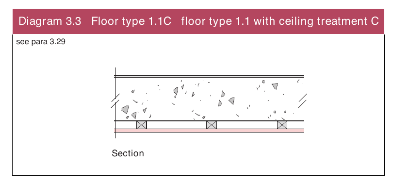
Floor Type 1.2B
3.30Concrete planks (solid or hollow), soft floor covering, ceiling treatment B
(see Diagram 3.4) – minimum mass per unit area of planks and any bonded screed of 365 kg/m2;
use a regulating floor screed; all floor joints fully grouted to ensure air tightness; soft floor covering (see para 3.28) essential; ceiling treatment B (or better) essential.
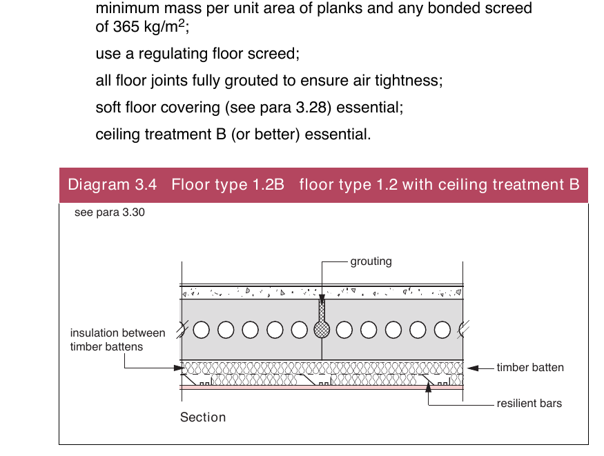
Junction requirements for floor type 1
#Source page 70
Junctions with an external cavity wall with masonry inner leaf
3.31Where the external wall is a cavity wall –
(a)the outer leaf of the wall may be of any construction; and
(b)the cavity should be closed with a cavity stop (see Diagram 3.5) ensuring adequate drainage, unless the cavity is fully filled with mineral wool or expanded polystyrene beads (seek manufacturer's advice for other suitable materials).
3.32The masonry inner leaf of an external cavity wall should have a mass per unit area of at least 120 kg/m2 excluding finish.
3.33The floor base (excluding any screed) should be built into a cavity masonry external wall and carried through to the cavity face of the inner leaf. The cavity should not be bridged.
Floor type 1.2B
3.34Where floor type 1.2B is used and the planks are parallel to the external wall the first joint should be a minimum of 300 mm from the cavity face of the inner leaf (see Diagram 3.5).
Diagram 3.5 Floor type 1.2B external cavity wall with masonry
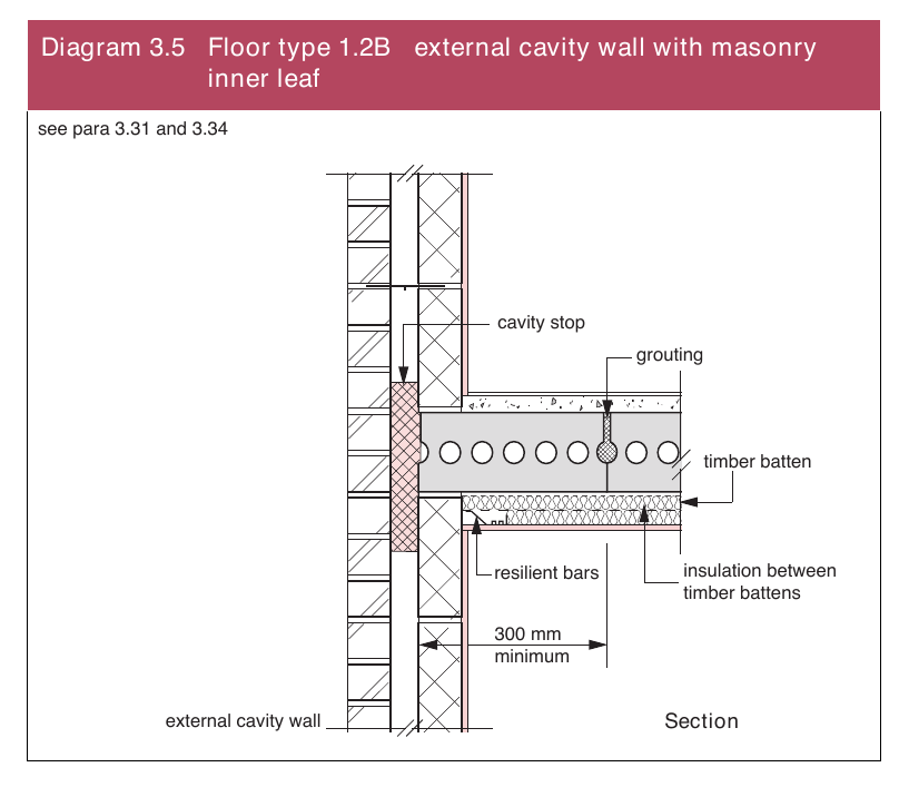
3.35See details in Section 2 concerning the use of wall ties in external masonry cavity walls.
Junctions with external cavity walls with timber frame inner leaf
#Source page 71
3.36Where the external wall is a cavity wall –
(a)the outer leaf of the wall may be of any construction;
(b)the cavity should be closed with a cavity stop; and
(c)the wall finish of the inner leaf of the external wall should be two layers of plasterboard, each sheet of plasterboard to be of minimum mass per unit area 10 kg/m2, and all joints should be sealed with tape or caulked with sealant.
Junctions with external solid masonry walls
3.37Seek specialist advice.
Junctions with internal framed walls
3.38There are no restrictions on internal framed walls meeting a type 1 separating floor.
Junctions with internal masonry walls
3.39The floor base should be continuous through, or above, an internal masonry wall.
3.40The mass per unit area of any loadbearing internal wall or any internal wall rigidly connected to a separating floor should be at least 120 kg/m2 excluding finish.
Junctions with floor penetrations (excluding gas pipes)
3.41Pipes and ducts that create a hole that penetrates a floor separating habitable rooms in different flats and maisonettes should be enclosed for the full height in each flat and maisonette (see Diagram 3.6).
Diagram 3.6 Floor type 1 floor penetrations
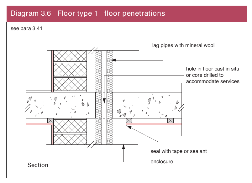
Junctions with separating wall type 1 – solid masonry
#Source page 72
3.42The enclosure should be constructed of material having a mass per unit area of at least 15 kg/m2. Either line the enclosure or wrap the duct or pipe within the enclosure with 25 mm unfaced mineral fibre.
3.43Penetrations through a separating floor by ducts and pipes should have fire protection.
Note – There are requirements for ventilation of ducts at each floor where they contain gas pipes. Gas pipes may be contained in a separate ventilated duct or they can remain unenclosed.
For flats and maisonettes where there are separating walls the following may also apply –
Junctions with separating wall type 1 – solid masonry
Floor type 1.1C
3.44A separating floor type 1.1C base (excluding any screed) should pass through a separating wall type 1 (see Diagram 3.7).
Diagram 3.7 Floor type 1.1C wall type 1
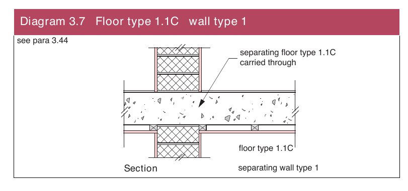
Floor type 1.2B
3.45A separating floor type 1.2B base (excluding any screed) should not be continuous through a separating wall type 1 (see Diagram 3.8).
Diagram 3.8 Floor type 1.2B wall type 1
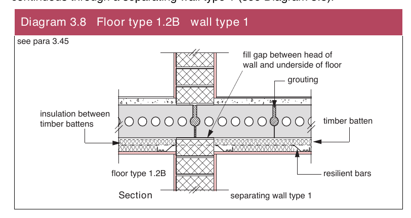
Junctions with separating wall type 2 – cavity masonry
#Source page 73
3.46The mass per unit area of any leaf that is supporting or adjoining the floor should be at least 120 kg/m2 excluding finish.
3.47The floor base (excluding any screed) should be carried through to the cavity face of the leaf. The wall cavity should not be bridged (see Diagram 3.9).
Floor type 1.2B
3.48Where floor type 1.2B is used and the planks are parallel to the separating wall the first joint should be a minimum of 300 mm from the inner face of the adjacent cavity leaf (see Diagram 3.9).
Diagram 3.9 Floor types 1.1C and 1.2B wall type 2
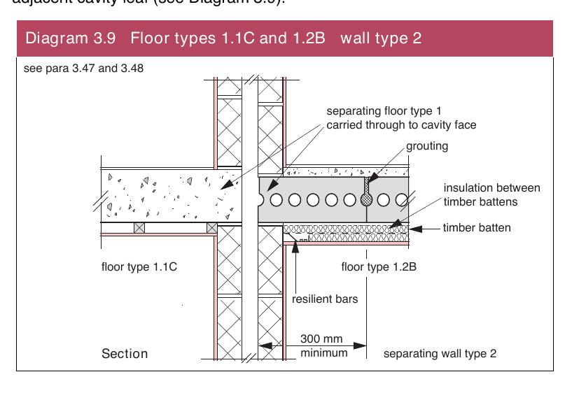
Junctions with separating wall type 3 – masonry between independent panels
#Source page 74
Junctions with separating wall type 3.1 and 3.2 (solid masonry core)
Floor type 1.1C
3.49A separating floor type 1.1C base (excluding any screed) should pass through separating wall types 3.1 and 3.2 (see Diagram 3.10).
Diagram 3.10 Floor type 1.1C wall types 3.1 and 3.2
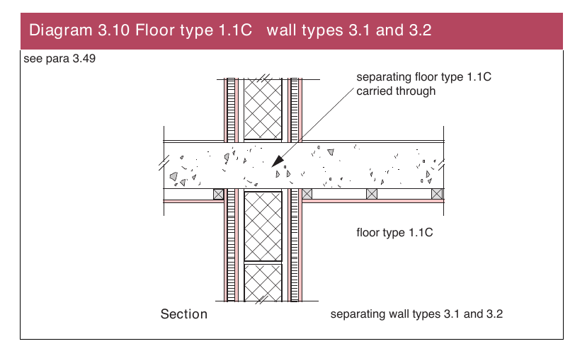
Floor type 1.2B
3.50A separating floor type 1.2B base (excluding any screed) should not be continuous through a separating wall type 3.
3.51Where separating wall type 3.2 is used with floor type 1.2B and the planks are parallel to the separating wall the first joint should be a minimum of 300 mm from the centreline of the masonry core.
Junctions with separating wall type 3.3 (cavity masonry core)
3.52The mass per unit area of any leaf that is supporting or adjoining the floor should be at least 120 kg/m2 excluding finish.
3.53The floor base (excluding any screed) should be carried through to the cavity face of the leaf of the core. The cavity should not be bridged.
Floor type 1.2B
3.54Where floor type 1.2B is used and the planks are parallel to the separating wall the first joint should be a minimum of 300 mm from the inner face of the adjacent cavity leaf of the masonry core.
Junctions with separating wall type 4 – timber frames with absorbent material
#Source page 75
3.55Seek specialist advice.
FLOOR TYPE 2 – CONCRETE BASE WITH CEILING AND FLOATING FLOOR
3.56The resistance to airborne and impact sound depends on the mass per unit area of the concrete base, as well as the mass per unit area and isolation of the floating layer and the ceiling. The floating floor reduces impact sound at source.
Constructions
3.57The construction consists of a concrete floor base with a floating floor and a ceiling. The floating floor consists of a floating layer and a resilient layer.
3.58Two floor type 2 constructions (types 2.1C and 2.2B) are described in this guidance (see paragraphs 3.67 and 3.68), which should be combined with the appropriate ceiling and any one of the three floating floor options (a), (b) or (c), (see paragraphs 3.62 to 3.66).
3.59Details of how junctions should be made to limit flanking transmission are also described in this guidance.
Limitations
3.60Where resistance to airborne sound only is required the full construction should still be used.
3.61Points to watch –
Do
(a)Do fill all joints between parts of the floor to avoid air paths.
(b)Do give special attention to workmanship and detailing at the perimeter and wherever a pipe or duct penetrates the floor in order to reduce flanking transmission and to avoid air paths.
(c)Do build a separating concrete floor base into the walls around its entire perimeter where the walls are masonry.
(d)Do fill with mortar any gap that may form between the head of a masonry wall and the underside of the concrete floor.
(e)Do control flanking transmission from walls connected to the separating floor as described in the guidance on junctions.
Do not
(f) Do not allow the floor base to bridge a cavity in a cavity masonry wall.
Floating floors (floating layers and resilient layers)
#Source page 76
3.62The floating floor consists of a floating layer and resilient layer (see Diagram 3.11).
Diagram 3.11 Floating floors (a) and (b)
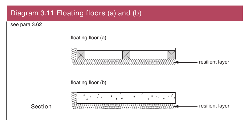
3.63Points to watch –
Do
(a)Do leave a small gap (as advised by the manufacturer) between the floating layer and wall at all room edges and fill with a flexible sealant.
(b)Do leave a small gap (approximately 5 mm) between skirting and floating layer and fill with a flexible sealant.
(c)Do lay resilient materials in rolls or sheets with lapped joints or with joints tightly butted and taped.
(d)Do use paper facing on the upper side of fibrous materials to prevent screed entering the resilient layer.
Do not
(e)Do not bridge between the floating layer and the base or surrounding walls (e.g. with services or fixings that penetrate the resilient layer).
(f)Do not let the floating screed create a bridge (e.g. through a gap in the resilient layer) to the concrete floor base or surrounding walls.
Floating floor (a)
3.64Timber raft floating layer with resilient layer
Floating floor (a) should meet the following specification – timber raft of board material (with bonded edges, e.g. tongued and grooved) of minimum mass per unit area 12 kg/m2, fixed to 45 mm x 45 mm battens;
timber raft to be laid loose on the resilient layer, battens should not be laid along any joints in the resilient layer;
resilient layer of mineral wool with density 36 kg/m3 and minimum thickness 25 mm. The resilient layer may be paper faced on the underside.
Page 77
#Source page 77
Floating floor (b)
3.65Sand cement screed floating layer with resilient layer
Floating floor (b) should meet the following specification – floating layer of 65 mm sand cement screed or a suitable proprietary screed product with a mass per unit area of at least 80 kg/m2. Ensure that the resilient layer is protected while the screed is being laid. A 2050 mm wire mesh may be used for this purpose;
resilient layer consisting of either –
(a)a layer of mineral wool of minimum thickness 25 mm with density 36 kg/m3, paper faced on the upper side to prevent the screed entering the resilient layer; or
(b)an alternative type of resilient layer which meets the following two requirements –
(i)maximum dynamic stiffness (measured according to BS EN 290521) of 15 MN/m3; and
(ii)minimum thickness of 5 mm under the load specified in the measurement procedure of BS EN 290521, 1.8 kPa to 2.1 kPa.
Note – For proprietary screed products, seek advice from the manufacturer.
Floating floor (c)
3.66Performance based approach
Floating floor (c) should meet the following specification – rigid boarding above a resilient and/or damping layer(s); with weighted reduction in impact sound pressure level (� .L w) of not less than 29 dB when measured according to BS EN ISO 1408 and rated according to BS EN ISO 7172 (see Appendix B). The performance value (� .Lw) should be achieved when the floating floor is both loaded and unloaded as described in BS EN ISO 1408 for category II systems.
Note – For details on the performance and installation of proprietary floating floors, seek advice from the manufacturer.
Floor type 2.1C
3.67Solid concrete slab (cast insitu, with or without permanent shuttering), floating floor, ceiling treatment C (see Diagrams 3.12 and 3.13) – minimum mass per unit area of 300 kg/m2 (including shuttering only if it is solid concrete or metal), and including any bonded screed;
regulating floor screed optional; floating floor (a), (b) or (c) essential; ceiling treatment C (or better) essential.
Page 78
#Source page 78
Diagram 3.12 Floor type 2.1C(a) floor type 2.1 with ceiling
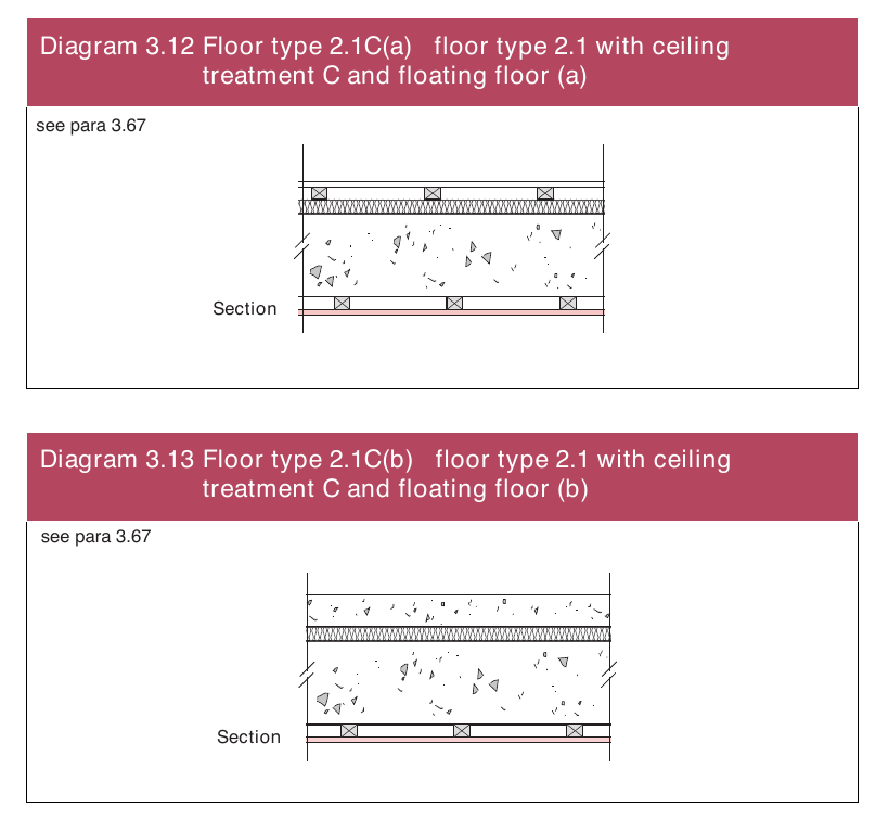
Floor type 2.2B
3.68Concrete planks (solid or hollow), floating floor, ceiling treatment B (see
Diagrams 3.14 and 3.15) – minimum mass per unit area of planks and any bonded screed of 300 kg/m2;
use a regulating floor screed; all floor joints fully grouted to ensure airtightness; floating floor (a), (b) or (c) essential; ceiling treatment B (or better) essential.
Diagram 3.14 Floor type 2.2B(a) floor type 2.2 with ceiling
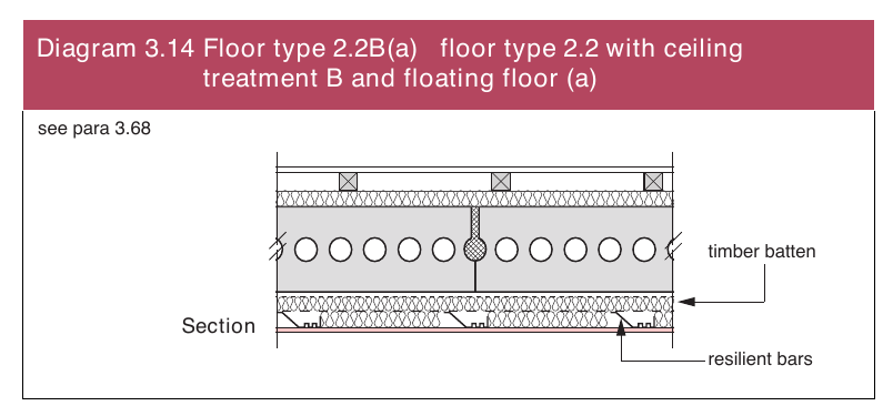
Junction requirements for floor type 2
#Source page 79
Diagram 3.15 Floor type 2.2B(b) floor type 2.2 with ceiling
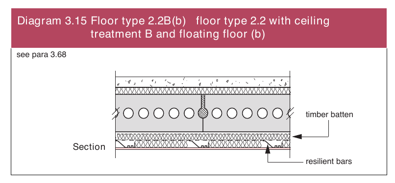
Junction requirements for floor type 2
Junctions with an external cavity wall with masonry inner leaf
3.69Where the external wall is a cavity wall –
(a)the outer leaf of the wall may be of any construction; and
(b)the cavity should be closed with a cavity stop (see Diagram 3.16) ensuring adequate drainage, unless the cavity is fully filled with mineral wool or expanded polystyrene beads (seek manufacturer's advice for other suitable materials).
Diagram 3.16 Floor type 2 external cavity wall with masonry
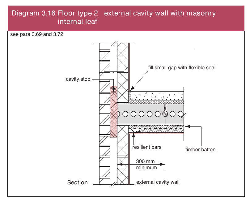
3.70The masonry inner leaf of an external cavity wall should have a mass per unit area of at least 120 kg/m2 excluding finish.
Floor 2.2B
#Source page 80
3.71The floor base (excluding any screed) should be built into a cavity masonry external wall and carried through to the cavity face of the inner leaf. The cavity should not be bridged.
Floor 2.2B
3.72Where floor 2.2B is used and the planks are parallel to the external wall the first joint should be a minimum of 300 mm from the cavity face of the inner leaf (see Diagram 3.16).
3.73See details in Section 2 concerning the use of wall ties in external masonry cavity walls.
Junctions with an external cavity wall with timber frame inner leaf
3.74Where the external wall is a cavity wall –
(a)the outer leaf of the wall may be of any construction;
(b)the cavity should be closed with a cavity stop; and
(c)the wall finish of the inner leaf of the external wall should be two layers of plasterboard, each sheet of plasterboard to be of minimum mass per unit area 10 kg/m2, and all joints should be sealed with tape or caulked with sealant.
Junctions with an external solid masonry wall
3.75Seek specialist advice.
Junctions with internal framed walls
3.76There are no restrictions on internal framed walls meeting a type 2 separating floor.
Junctions with internal masonry walls
3.77The floor base should be continuous through, or above an internal masonry wall.
3.78The mass per unit area of any loadbearing internal wall or any internal wall rigidly connected to a separating floor should be at least 120 kg/m2 excluding finish.
Junctions with floor penetrations (excluding gas pipes)
#Source page 81
3.79Pipes and ducts that penetrate a floor separating habitable rooms in different flats and maisonettes should be enclosed for the full height in each flat and maisonette (see Diagram 3.17).
Diagram 3.17 Floor type 2 floor penetrations
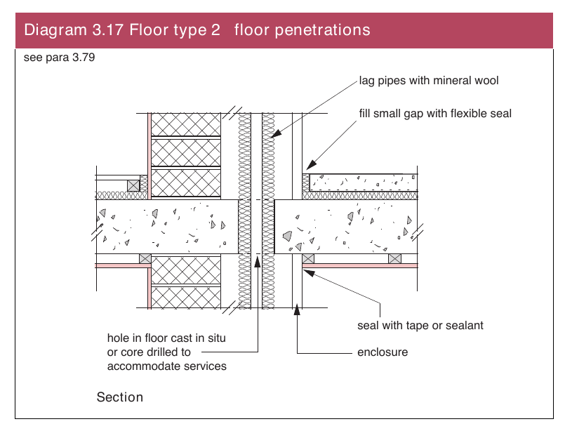
3.80The enclosure should be constructed of material having a mass per unit area of at least 15 kg/m2. Either line the enclosure, or wrap the duct or pipe within the enclosure, with 25 mm unfaced mineral wool.
3.81Leave a small gap (approximately 5 mm) between the enclosure and floating layer and seal with sealant or neoprene. Where floating floor (a) or
(b) is used the enclosure may go down to the floor base, but ensure that the enclosure is isolated from the floating layer.
3.82Penetrations through a separating floor by ducts and pipes should have fire protection.
For flats and maisonettes where there are separating walls the following may also apply –
Junctions with a separating wall type 1 – solid masonry
Floor type 2.1C
3.83A separating floor type 2.1C base (excluding any screed) should pass through a separating wall type 1.
Floor type 2.2B
#Source page 82
3.84A separating floor type 2.2B base (excluding any screed) should not be continuous through a separating wall type 1 (see Diagram 3.18).
Diagram 3.18 Floor types 2.2B(a) and 2.2B(b) wall type 1
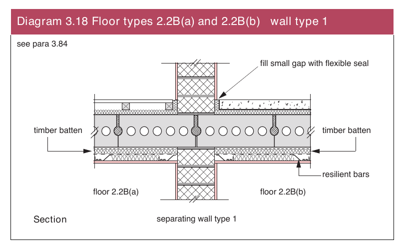
Junctions with a separating wall type 2 – cavity masonry
3.85The floor base (excluding any screed) should be carried through to the cavity face of the leaf. The cavity should not be bridged.
Floor type 2.2B
3.86Where floor type 2.2B is used and the planks are parallel to the separating wall the first joint should be a minimum of 300 mm from the cavity face of the leaf.
Junctions with a separating wall type 3 – masonry between independent panels
Junctions with separating wall type 3.1 and 3.2 (solid masonry core)
Floor type 2.1C
3.87A separating floor type 2.1C base (excluding any screed) should pass through separating wall types 3.1 and 3.2 (see Diagram 3.19).
Floor type 2.2B
#Source page 83
Diagram 3.19 Floor type 2.1C wall types 3.1 and 3.2
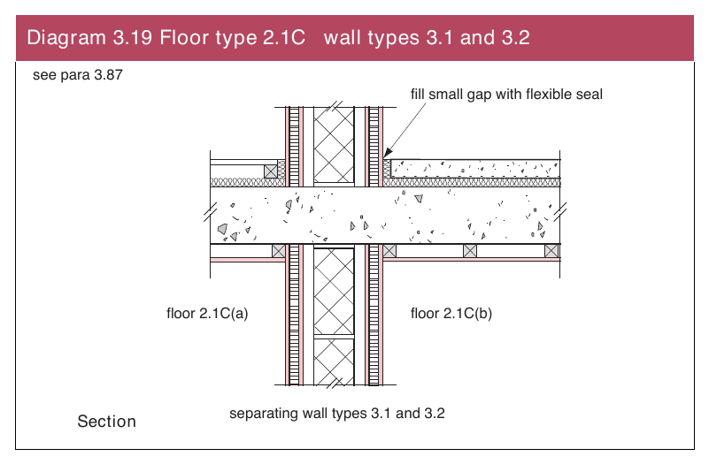
Floor type 2.2B
3.88A separating floor type 2.2B base (excluding any screed) should not be continuous through a separating wall type 3.
3.89Where separating wall type 3.2 is used with floor type 2.2B and the planks are parallel to the separating wall the first joint should be a minimum of 300 mm from the centreline of the masonry core.
Junctions with separating wall type 3.3 (cavity masonry core)
3.90The mass per unit area of any leaf that is supporting or adjoining the floor should be at least 120 kg/m2 excluding finish.
3.91The floor base (excluding any screed) should be carried through to the cavity face of the leaf of the core. The cavity should not be bridged.
Floor type 2.2B
3.92Where floor type 2.2B is used and the planks are parallel to the separating wall the first joint should be a minimum of 300 mm from the inner face of the adjacent cavity leaf of the masonry core.
Junctions with separating wall type 4 – timber frames with absorbent material
3.93Seek specialist advice.
FLOOR TYPE 3 – TIMBER FRAME BASE WITH CEILING AND PLATFORM FLOOR
#Source page 84
3.94The resistance to airborne and impact sound depends on the structural floor base and the isolation of the platform floor and the ceiling. The platform floor reduces impact sound at source.
Construction
3.95The construction consists of a timber frame structural floor base with a deck, platform floor and ceiling treatment A. The platform floor consists of a floating layer and a resilient layer.
3.96One floor type 3 construction (type 3.1A) is described in this guidance.
3.97Details of how junctions should be made to limit flanking transmission are also described in this guidance.
Limitations
3.98Where resistance to airborne sound only is required the full construction should still be used.
3.99Points to watch –
Do
(a)Do give special attention to workmanship and detailing at the perimeter and wherever the floor is penetrated, to reduce flanking transmission and to avoid air paths.
(b)Do control flanking transmission from walls connected to the separating floor as described in the guidance on junctions.
Platform floor
(c)Do use the correct density of resilient layer and ensure it can carry the anticipated load.
(d)Do use an expanded or extruded polystyrene strip (or similar resilient material) around the perimeter which is approximately 4 mm higher than the upper surface of the floating layer to ensure that during construction a gap is maintained between the wall and the floating layer. This gap may be filled with a flexible sealant.
(e)Do lay resilient materials in sheets with joints tightly butted and taped.
Do not
(f) Do not bridge between the floating layer and the base or surrounding walls (e.g. with services or fixings that penetrate the resilient layer).
Floor type 3.1A
#Source page 85
3.100Timber frame base with ceiling treatment A and platform floor (see Diagram 3.20) – timber joists with a deck; the deck should be of any suitable material with a minimum mass per unit area of 20 kg/m2;
platform floor (including resilient layer) essential; ceiling treatment A essential.
Diagram 3.20 Floor type 3.1A
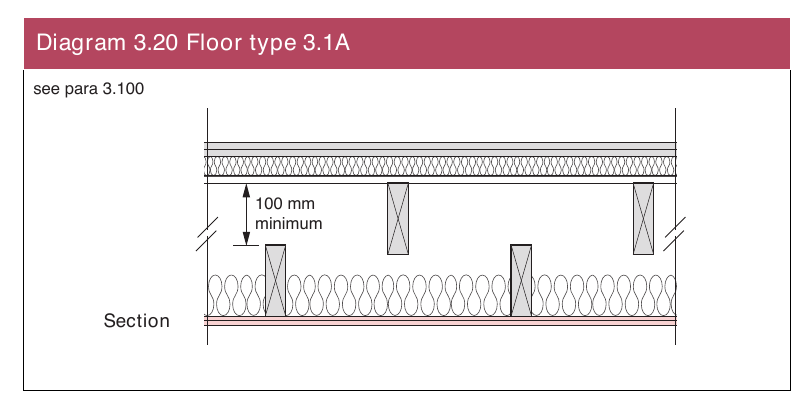
Platform floor
3.101The floating layer should be – a minimum of two layers of board material; a minimum total mass per unit area 25 kg/m2; each layer of minimum thickness 8 mm; and fixed together (e.g. spot bonded with a resilient adhesive or glued/screwed) with joints staggered.
The floating layer should be laid loose on a resilient layer.
Example 1 –
18mm timber or wood based board tongued and grooved edges and glued joints spot bonded to a substrate of 19 mm plasterboard with joints staggered minimum total mass per unit area 25 kg/m2.
Example 2 – two layers of cement bonded particle board with staggered joints total thickness 24 mm boards glued and screwed together minimum total mass per unit area 25 kg/m2.
Resilient layer
#Source page 86
3.102The resilient layer specification is – mineral wool, minimum thickness 25 mm, density 60 to 100 kg/m3; the mineral wool may be paper faced on the underside.
Note – The lower figure of density for the resilient layer gives a higher resistance to impact sound but a "softer" floor. In such cases additional support can be provided around the perimeter of the floor by using a timber batten with a foam strip along the top attached to the wall.
Junction requirements for floor type 3
Junctions with an external cavity wall with masonry inner leaf
3.103Where the external wall is a cavity wall –
(a)the outer leaf of the wall may be of any construction; and
(b)the cavity should be closed with a cavity stop unless the cavity is fully filled with mineral wool or expanded polystyrene beads (seek manufacturer's advice for other suitable materials).
3.104The masonry inner leaf of a cavity wall should be lined with an independent panel as described for wall type 3.
3.105The ceiling should be taken through to the masonry. The junction between the ceiling and the independent panel should be sealed with tape or caulked with sealant.
3.106Use any normal method of connecting floor base to wall but block air paths between floor and wall cavities.
3.107Where the mass per unit area of the inner leaf is greater than 375 kg/m2 the independent panels are not required.
3.108See details in Section 2 concerning the use of wall ties in external masonry cavity walls.
Junctions with an external cavity wall with timber frame inner leaf
3.109Where the external wall is a cavity wall –
(a)the outer leaf of the wall may be of any construction; and
(b)the cavity should be closed with a cavity stop.
3.110The wall finish of the inner leaf of the external wall should be –
(a)two layers of plasterboard;
(b)each sheet of plasterboard of minimum mass per unit area 10 kg/m2; and
(c)all joints should be sealed with tape or caulked with sealant.
3.111Use any normal method of connecting floor base to wall. Where the joists are at right angles to the wall, spaces between the floor joists should be sealed with full depth timber blocking. Any voids to be filled with flexible caulking.
Junctions with an external solid masonry wall
#Source page 87
3.112The junction between the ceiling and wall lining should be sealed with tape or caulked with sealant.
Junctions with an external solid masonry wall
3.113Seek specialist advice.
Junctions with internal framed walls
3.114Where the joists are at right angles to the wall, spaces between the floor joists should be sealed with full depth timber blocking. Any voids to be filled with flexible caulking.
3.115The junction between the ceiling and the internal framed wall should be sealed with tape or caulked with sealant.
Junctions with internal masonry walls
3.116Seek specialist advice.
Junctions with floor penetrations (excluding gas pipes)
3.117Pipes and ducts that penetrate a floor separating habitable rooms in different flats and maisonettes should be enclosed for their full height in each flat and maisonette (see Diagram 3.21).
Diagram 3.21 Floor type 3 floor penetrations
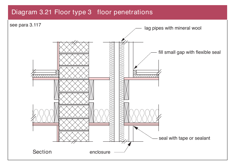
3.118The enclosure should be constructed of material having a mass per unit area of at least 15 kg/m2. Either line the enclosure, or wrap the duct or pipe within the enclosure, with 25 mm unfaced mineral wool.
3.119Leave a small gap (approximately 5 mm) between enclosure and floating layer and seal with sealant or neoprene. The enclosure may go down to the floor base, but ensure that the enclosure is isolated from the floating layer.
For flats and maisonettes where there are separating walls the following may also apply –
#Source page 88
3.120Penetrations through a separating floor by ducts and pipes should have fire protection.
For flats and maisonettes where there are separating walls the following may also apply –
Junctions with a separating wall type 1 – solid masonry
3.121If floor joists are to be supported by the separating wall then they should be supported on hangers and should not be built in (see Diagram 3.22).
3.122The junction between the ceiling and wall should be sealed with tape or caulked with sealant.
Diagram 3.22 Floor type 3 wall type 1
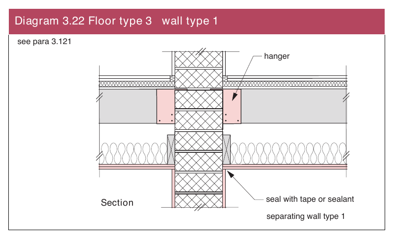
Junctions with a separating wall type 2 – cavity masonry
3.123If floor joists are to be supported by the separating wall then they should be supported on hangers and should not be built in (see Diagram 3.23).
3.124The adjacent leaf of a cavity separating wall should be lined with an independent panel as described in wall type 3.
3.125The ceiling should be taken through to the masonry. The junction between the ceiling and the independent panel should be sealed with tape or caulked with sealant.
3.126Where the mass per unit area of the adjacent leaf is greater than 375 kg/m2 the independent panels are not required.
Junctions with a separating wall type 3 – masonry between independent panels
#Source page 89
Diagram 3.23 Floor type 3 wall type 2
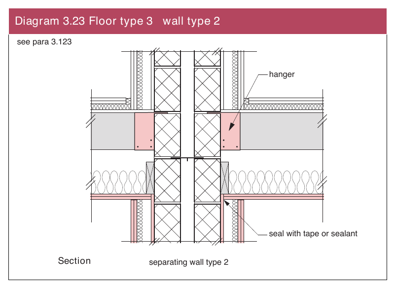
Junctions with a separating wall type 3 – masonry between independent panels
3.127If floor joists are to be supported by the separating wall then they should be supported on hangers and should not be built in.
3.128The ceiling should be taken through to the masonry. The junction between the ceiling and the independent panel should be sealed with tape or caulked with sealant.
Junctions with a separating wall type 4 – timber frames with absorbent material
3.129Where the joists are at right angles to the wall, spaces between the floor joists should be sealed with full depth timber blocking. Any voids to be filled with flexible caulking.
3.130The junction of the ceiling and wall lining should be sealed with tape or caulked with sealant.
General
#Source page 90
Section 4 Dwellings formed by material change of use
General
4.1This Section gives guidance on dwellings formed by material change of use. For rooms for residential purposes formed by material change of use see Section 6. Precompletion testing will establish the compliance of the constructions with Part G.
4.2It may be that an existing wall, floor or stair in a building that is to undergo material change of use will achieve the performance standards set out in Table 1a of the section entitled “Guidance Performance and introduction to provisions” without the need for remedial work. This would be the case if the construction was generally similar (including flanking constructions) to one of the constructions in Sections 2 and 3 (e.g. concerning the mass requirement, the structure under consideration should be within 15% of the mass per unit area of a construction listed in the relevant section).
4.3In other circumstances it may be possible to use the guidance in Section 2 or 3 (including flanking constructions) to determine the appropriate remedial treatment which will result in the construction achieving the performance standards set out in Table 1a of the section entitled “Guidance Performance and introduction to provisions”.
4.4For situations where it cannot be shown that the existing construction achieves the performance standards set out in Table 1a of the section entitled “Guidance Performance and introduction to provisions”, this section describes one wall treatment, two floor treatments and one stair treatment as shown in Diagram 4.1. These constructions can be used to improve the sound insulation of the existing constructions.
4.5The guidance in this section is not exhaustive and other designs, materials or products may be used to achieve the performance standards set out in Table 1a of the section entitled “Guidance Performance and introduction to provisions”. Advice should be sought from the manufacturer or other appropriate source.
Wall treatment 1 – Independent panel(s) with absorbent material
4.6The resistance to airborne sound depends on the form of the existing construction, the mass of the independent panel(s), the isolation of the panel(s) and the absorbent material.
Floor treatment 1 – Independent ceiling with absorbent material
4.7The resistance to airborne and impact sound depends on the combined mass of the existing floor and the independent ceiling, the absorbent material, the isolation of the independent ceiling and the airtightness of the whole construction.
Floor treatment 2 – Platform floor with absorbent material
4.8
The resistance to airborne and impact sound depends on the total mass of the floor, the effectiveness of the resilient layer and the absorbent material.
Page 91
#Source page 91
Stair treatment 1 – Stair covering and independent ceiling with absorbent material
4.9To be used where a timber stair performs a separating function. The resistance to airborne sound depends mainly on the mass of the stair, the mass and isolation of any independent ceiling and the airtightness of any cupboard or enclosure under the stairs. The stair covering reduces impact sound at source.
4.10In all cases it may be necessary to control flanking transmission in order to achieve the performance standards set out in Table 1a of the section entitled “Guidance Performance and introduction to provisions” (see Section 4: Junction requirements for material change of use).
4.11Special attention needs to be given to situations where flanking walls or floors are continuous across separating walls or floors as a result of the conversion work. In such instances additional treatments may be required to control flanking transmission along these continuous elements. Specialist advice may be needed.
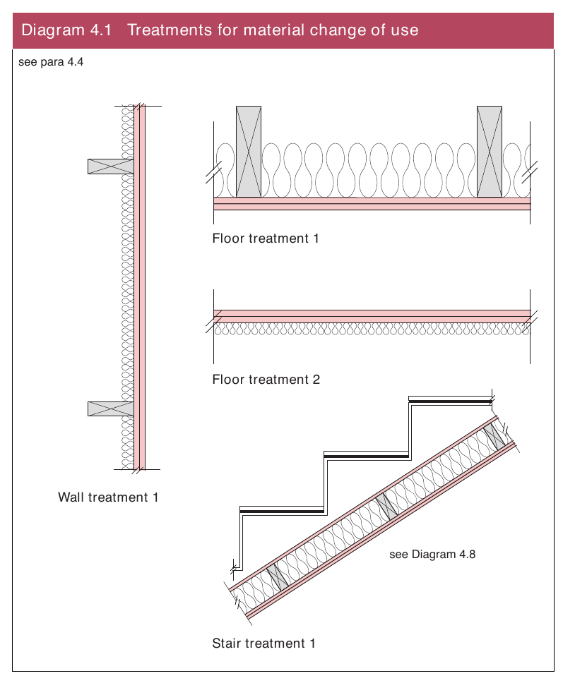
Work to existing construction
#Source page 92
4.12Significant differences may frequently occur between the construction and layout of each converted unit in a development. District councils should have regard to the guidance in Section 1 when deciding on the application of precompletion testing to material change of use.
4.13For some historic buildings undergoing material change of use, it may not be practicable to improve the sound insulation to the performance standards set out in Table 1a of the section entitled “Guidance Performance and introduction to provisions” and in such cases refer to paragraph 0.19 of that section.
4.14Wall and floor treatments will impose additional loads on the existing structure. The structure should be assessed to ensure that the additional loading can be carried safely, with appropriate strengthening applied where necessary.
4.15Floor or wall penetrations, such as ducts or pipes, passing through separating elements in conversions can reduce the level of sound insulation. Guidance on the treatment of floor penetrations is given in paragraphs 4.44 to 4.49 and Diagram 4.9.
Work to existing construction
4.16Before a floor treatment is applied appropriate remedial work to the existing construction should be undertaken as described in paragraphs 4.17 and 4.18.
4.17If the existing floor is timber then gaps in floor boarding should be sealed by overlaying with hardboard or filled with sealant –
(a)Where floor boards are to be replaced, boarding should have a minimum thickness of 12 mm, and mineral wool (minimum thickness 100 mm, minimum density 10 kg/m3) should be laid between the joists in the floor cavity.
(b)If the existing floor is concrete and the mass per unit area of the concrete floor is less than 300 kg/m2, or is unknown, then the mass of the floor should be increased to at least 300 kg/m2. Any air gaps through a concrete floor should be sealed. A regulating screed may also be required.
(c)If there is an existing lath and plaster ceiling it should be retained as long as it satisfies other requirements.
(d)Where the existing ceiling is not lath and plaster it should be upgraded as necessary to provide at least two layers of plasterboard with joints staggered, total mass per unit area 20 kg/m2.
4.18Extensive remedial work to reduce flanking transmission may also be necessary to achieve the performance standards set out in Table 1a of the section entitled “Guidance Performance and introduction to provisions”. This may involve wall linings, see Section 4: Junction requirements for material change of use, paragraphs 4.42 and 4.43.
Corridor walls and doors
#Source page 93
4.19The separating walls described in this section should be used between dwellings formed by material change of use, and corridors in order to control flanking transmission and to provide the required sound insulation. However, it is likely that the sound insulation will be reduced by the presence of a door.
4.20Ensure that any door in a separating wall has good perimeter sealing (including the threshold where practical) and a minimum mass per unit area of 25 kg/m2 or a minimum sound reduction index of 29 dB Rw (measured according to BS EN ISO 1403 and rated according to BS EN ISO 7171).
4.21Noisy parts of the building should preferably have a lobby, double door or high performance doorset to contain the noise. Where this is not possible, nearby flats and maisonettes should have similar protection.
Wall treatment 1 – independent panel(s) with absorbent material
4.22The resistance to airborne sound depends on the form of existing construction, the mass of independent panel(s), the isolation of the panel(s) and the absorbent material.
Construction
4.23The independent panel may be used on one side of the existing wall only where the existing wall is masonry, and has a thickness of at least 100 mm and is plastered on both faces. With other types of existing wall the independent panels should be built on both sides.
4.24Independent panel(s) with absorbent material (see Diagram 4.2) should consist of – a minimum mass per unit area of panel (excluding any supporting framework) 20 kg/m2;
each panel having at least two layers of plasterboard with staggered joints;
where the panels are freestanding, they should be at least 35 mm from the masonry core;
where the panels are supported on a frame, there should be a gap of at least 10 mm between the frame and the face of the existing wall; and mineral wool, minimum density 10 kg/m3 and minimum thickness 35 mm, in the cavity between the panel and the existing wall.
4.25 Points to watch –
#Source page 94
Do
(a)Do ensure that the independent panel and its supporting frame are not in contact with the existing wall.
(b)Do seal the perimeter of the independent panel with tape or sealant.
Do not
(c)Do not tightly compress the absorbent material as this may bridge the cavity.
Floor treatment 1 – independent ceiling with absorbent material
4.26The resistance to airborne and impact sound depends on the combined mass of the existing floor and the independent ceiling, the absorbent material, the isolation of the independent ceiling and the airtightness of the whole construction.
4.27Independent ceiling with absorbent material (see Diagram 4.3) –
having at least 2 layers of plasterboard with staggered joints, minimum total mass per unit area 20 kg/m²; and
an absorbent layer of mineral wool laid on the ceiling, minimum thickness 100 mm, minimum density 10 kg/m³.
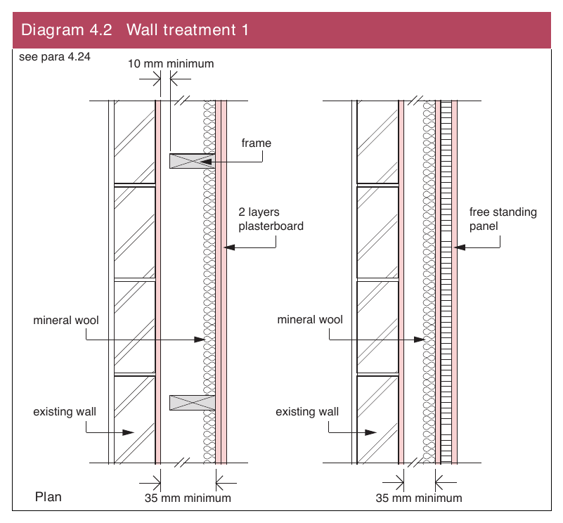
Page 95
#Source page 95
The ceiling should be supported by one of the following methods –
(a)independent joists fixed only to the surrounding walls. A clearance of at least 25 mm should be left between the top of the independent ceiling joists and the underside of the existing floor construction; or
(b)independent joists fixed to the surrounding walls with additional support provided by resilient hangers attached directly to the existing floor base.
Note – This construction involves a separation of at least 125 mm between the upper surface of the independent ceiling and the underside of the existing floor construction. However, structural considerations determining the size of ceiling joists will often result in greater separation. Care should be taken at the design stage to ensure that adequate ceiling height is available in all rooms to be treated.
Diagram 4.3 Floor treatment 1
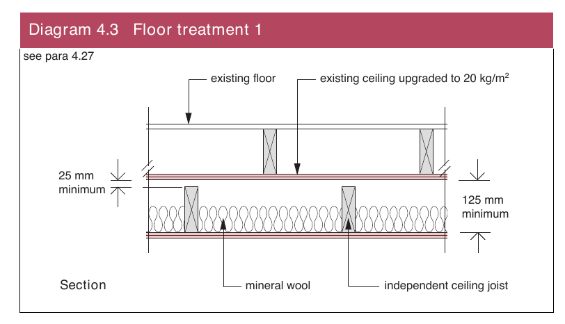
4.28Where a window head is near to the existing ceiling, the new independent ceiling may be raised to form a pelmet recess (see Diagram 4.4).
Diagram 4.4 Floor treatment 1 high window head detail
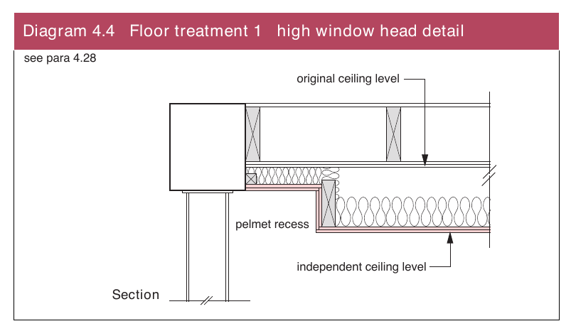
Do not
#Source page 96
4.29For the junction detail between floor treatment 1 and wall treatment 1
(see Diagram 4.5).
Diagram 4.5 Floor treatment 1 wall treatment 1
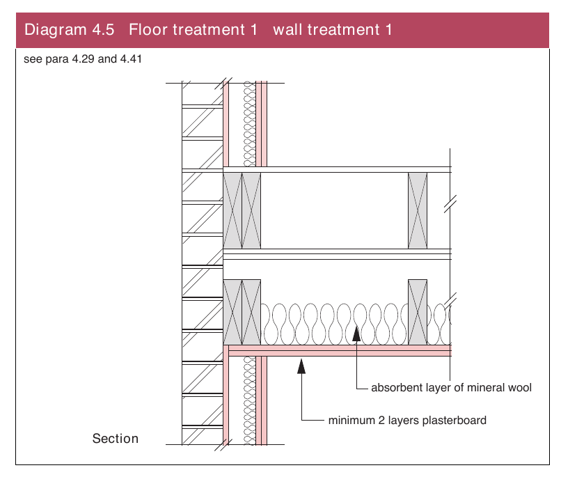
4.30Points to watch –
Do
(a)Do remember to apply appropriate remedial work to the existing construction.
(b)Do seal the perimeter of the independent ceiling with tape or sealant.
Do not
(c)Do not create a rigid or direct connection between the independent ceiling and the floor base.
(d)Do not tightly compress the absorbent material as this may bridge the cavity.
Floor treatment 2 – platform floor with absorbent material
#Source page 97
4.31The resistance to airborne and impact sound depends on the total mass of the floor, the effectiveness of the resilient layer and the absorbent material.
4.32Platform floor with absorbent material (see Diagram 4.6)
Diagram 4.6 Floor treatment 2
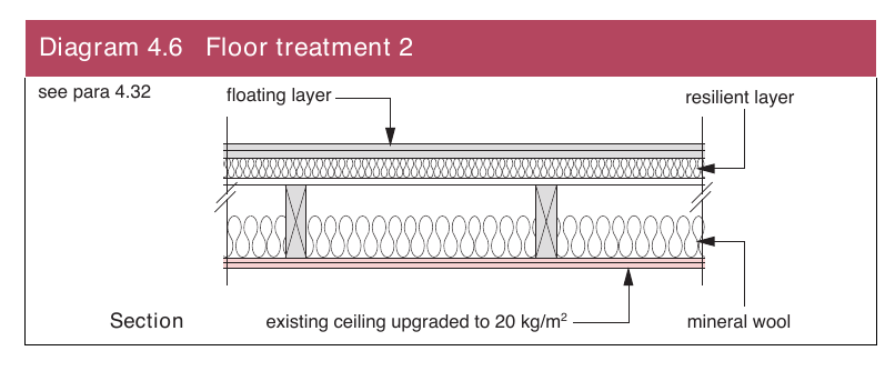
Where this treatment is used to improve an existing timber floor, a layer of mineral wool (minimum thickness 100 mm, minimum density 10 kg/m3) should be laid between the joists in the floor cavity.
The floating layer should be – a minimum of two layers of board material;
minimum total mass per unit area 25 kg/m2;
each layer of minimum thickness 8 mm; and fixed together (e.g. spot bonded or glued/screwed) with joints staggered.
The floating layer should be laid loose on a resilient layer.
The resilient layer specification is – mineral wool, minimum thickness 25 mm, density 60 to 100 kg/m3; and the mineral wool may be paper faced on the underside.
Note – The lower figure of density for the resilient layer gives the best insulation but a "softer" floor. In such cases additional support can be provided around the perimeter of the floor by using a timber batten with a foam strip along the top attached to the wall.
Diagram 4.7 Floor treatment 2 wall treatment 1
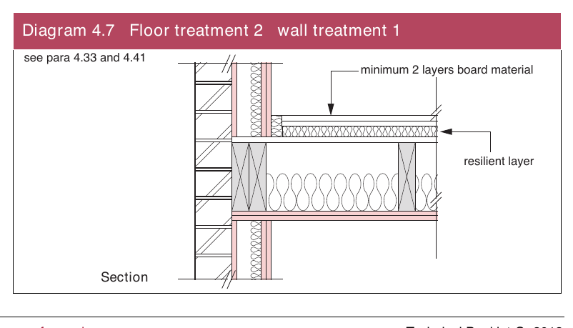
Do not
#Source page 98
4.33For the junction detail between floor treatment 2 and wall treatment 1 (see Diagram 4.7).
4.34Points to watch –
Do
(a)Do remember to apply appropriate remedial work to the existing construction.
(b)Do use the correct density of resilient layer and ensure it can carry the anticipated load.
(c)Do allow for movement of materials e.g. expansion of chipboard after laying (to maintain isolation).
(d)Do carry the resilient layer up at all room edges to isolate the floating layer from the wall surface.
(e)Do leave a small gap (approximately 5 mm) between skirting and floating layer and fill with a flexible sealant.
(f)Do lay resilient materials in sheets with joints tightly butted and taped.
(g)Do seal the perimeter of any new ceiling with tape or sealant.
Do not
(h) Do not bridge between the floating layer and the base or surrounding walls (e.g. with services or fixings that penetrate the resilient layer).
Stair treatment 1 – stair covering and independent ceiling with absorbent material
4.35Stairs are subject to the same sound insulation requirements as floors where they perform a separating function.
4.36The resistance to airborne sound depends mainly on the mass of the stair, the mass and isolation of any independent ceiling and the airtightness of any cupboard or enclosure under the stairs. The stair covering reduces impact sound at source.
4.37Stair covering and independent ceiling with absorbent material (see Diagram 4.8).
Lay soft covering of at least 6 mm thickness over the stair treads. Ensure it is securely fixed (e.g. glued) so it does not become a safety hazard.
If there is a cupboard under all, or part, of the stair –
(a)line the underside of the stair within the cupboard with plasterboard of minimum mass per unit area 10 kg/m2 and an absorbent layer of mineral wool (minimum density 10 kg/m3), within the space above the lining; and
(b)build cupboard walls from two layers of plasterboard (or equivalent) with staggered joints, each sheet of minimum mass per unit area 10 kg/m2; and
(c)use a small, heavy, well fitted door for the cupboard.
Where there is no cupboard under the stair, construct an independent ceiling below the stair (see para 4.26 Floor treatment 1).
Junction requirements for material change of use
#Source page 99
Diagram 4.8 Stair treatment (without cupboard)
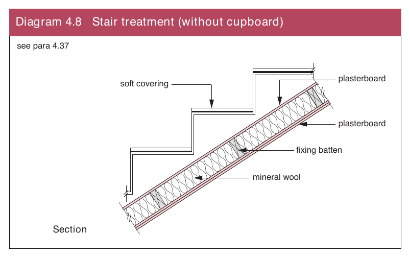
Junction requirements for material change of use
Junctions with abutting construction
4.38For floating floors, carry the resilient layer up at all room edges to isolate the floating layer from the wall surface.
4.39For floating floors, leave a small gap (approximately 5 mm) between the skirting and floating layer and fill with a flexible sealant.
4.40The perimeter of any new ceiling should be sealed with tape or caulked with sealant.
4.41Relevant junction details are shown in Diagrams 4.5 and 4.7.
Junctions with external or loadbearing walls
4.42Where there is significant flanking transmission along adjoining walls then improved sound insulation can be achieved by lining all adjoining masonry walls with either –
(a)an independent layer of plasterboard; or
(b)a laminate of plasterboard and mineral wool. For other drylining laminates, seek advice from the manufacturer.
4.43Where the adjoining masonry wall has a mass per unit area greater than 375 kg/m2 then such lining may not be necessary, as it may not give a significant improvement.
Note – Specialist advice may be needed on the diagnosis and control of flanking transmission.
Junctions with floor penetrations
#Source page 100
4.44Piped services (excluding gas pipes) and ducts which pass through separating floors in conversions should be surrounded with sound absorbent material for their full height and enclosed in a duct above and below the floor.
Do
(a)Do seal the joint between casings and ceiling with tape or sealant.
(b)Do leave a nominal gap (approximately 5 mm) between the casing and any floating layer and fill with sealant.
Construction
4.45Pipes and ducts that penetrate a floor separating habitable rooms in different flats and maisonettes should be enclosed for their full height in each flat and maisonette (see Diagram 4.9).
4.46The enclosure should be constructed of material having a mass per unit area of at least 15 kg/m2.
4.47Either line the enclosure, or wrap the duct or pipe within the enclosure, with 25 mm unfaced mineral wool.
4.48The enclosure may go down to the floor base if floor treatment 2 is used but ensure isolation from the floating layer.
4.49Penetrations through a separating floor by ducts and pipes should have fire protection.
Diagram 4.9 Floor penetrations
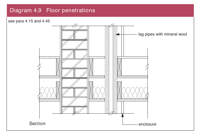
General
#Source page 101
Section 5 Internal walls and floors for new buildings
General
5.1This Section gives examples of internal wall and floor constructions that meet the laboratory sound insulation values set out in Table 2 of the section entitled “Guidance Performance and introduction to provisions”. Precompletion testing is not a requirement for internal walls and floors.
5.2These constructions have been designed to give insulation against airborne sound. For internal floors, insulation against impact sound could be improved by adding a bonded soft covering.
5.3They are grouped in four main types as shown below.
Internal wall type A or B: Timber or metal frame
5.4The resistance to airborne sound depends on the mass per unit area of the leaves, the cavity width, frame material and the absorption in the cavity between the leaves.
Internal wall type C or D: Concrete or aircrete block
5.5The resistance to airborne sound depends mainly on the mass per unit area of the wall.
Internal floor type A or B: Concrete planks or concrete beams with infilling blocks
5.6The resistance to airborne sound depends on the mass per unit area of the concrete base or concrete beams and infilling blocks. A soft covering will reduce impact sound at source.
Internal floor type C: Timber or metal joist
5.7The resistance to airborne sound depends on the structural floor base, the ceiling and the absorbent material. A soft covering will reduce impact sound at source.
5.8For both internal walls and internal floors the constructions are ranked, as far as possible, with constructions giving better sound insulation given first.
Doors
5.9Lightweight doors with poor perimeter sealing provide a lower standard of sound insulation than walls. This will reduce the effective sound insulation of the internal wall. Ways of improving sound insulation include ensuring that there is good perimeter sealing or by using a doorset.
Layout
5.10If the stair is not enclosed, then the potential sound insulation of the internal floor will not be achieved; nevertheless, the internal floor should still satisfy Part G.
Junction requirements for internal walls
#Source page 102
5.11It is good practice to consider the layout of rooms at the design stage to avoid placing noise sensitive rooms next to rooms in which noise is generated. Guidance on layout is provided in BS 8233.
Junction requirements for internal walls
5.12Section 3: Separating Floors contains important guidance on junctions of separating floors with internal walls.
5.13Fill all gaps around internal walls to avoid air paths between rooms.
Junction requirements for internal floors
5.14Section 2: Separating Walls contains important guidance on junctions of separating walls with internal floors.
5.15Fill all gaps around internal floors to avoid air paths between rooms.
Internal wall type A:
5.16Timber or metal frames with plasterboard linings on each side of frame (see Diagram 5.1) each lining to be two or more layers of plasterboard with staggered joints, each sheet of minimum mass per unit area 10 kg/m2;
linings fixed to timber frame with a minimum distance between linings of 75 mm, or metal frame with a minimum distance between linings of 45 mm;
all joints well sealed.
Diagram 5.1 Internal wall type A
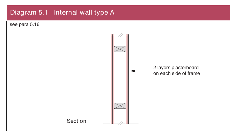
Internal wall type B:
#Source page 103
5.17Timber or metal frames with plasterboard linings on each side of frame and absorbent material (see Diagram 5.2) – single layer of plasterboard of minimum mass per unit area 10 kg/m2;
linings fixed to timber frame with a minimum distance between linings of 75 mm, or metal frame with a minimum distance between linings of 45 mm;
an absorbent layer of unfaced mineral wool batts or quilt (minimum thickness 25 mm, minimum density 10 kg/m3) which may be wire reinforced, suspended in the cavity;
all joints well sealed.
Diagram 5.2 Internal wall type B
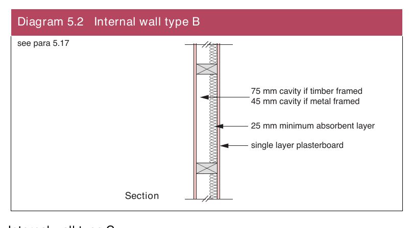
Internal wall type C:
5.18Concrete block wall, plaster or plasterboard finish on both sides (see Diagram 5.3) – minimum mass per unit area, excluding finish 120 kg/m2;
all joints well sealed; plaster or plasterboard finish on both sides.
Diagram 5.3 Internal wall type C
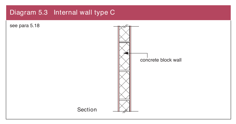
Internal wall type D:
#Source page 104
5.19Aircrete block wall, plaster or plasterboard finish on both sides (see Diagram 5.4) – for plaster finish, minimum mass per unit area, including finish 90 kg/m2;
for plasterboard finish, minimum mass per unit area, including finish 75 kg/m2;
all joints well sealed;
internal wall type D should only be used with the separating walls described in this Technical Booklet where there is no minimum mass requirement on the internal masonry walls (see guidance in Section 2);
internal wall type D should not be used as a loadbearing wall connected to a separating floor, or be rigidly connected to the separating floors described in this Technical Booklet (see guidance in Section 3).
Diagram 5.4 Internal wall type D
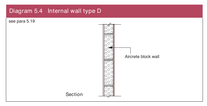
Internal floor type A:
5.20Concrete planks (see Diagram 5.5) – minimum mass per unit area 180 kg/m2; regulating screed optional; ceiling finish optional.
Diagram 5.5 Internal floor type A
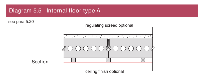
Note – Insulation against impact sounds can be improved by adding a soft floor finish such as a carpet.
Internal floor type B:
#Source page 105
5.21Concrete beams with infilling blocks, bonded screed and ceiling (see Diagram 5.6) – minimum mass per unit area of beams and blocks 220 kg/m2;
bonded screed required. Sand cement screeds should have a minimum thickness of 40 mm. For proprietary bonded screed products, seek manufacturer's advice on the appropriate thickness;
ceiling finish required. Use ceiling treatment C or better from Section 3.
Diagram 5.6 Internal floor type B
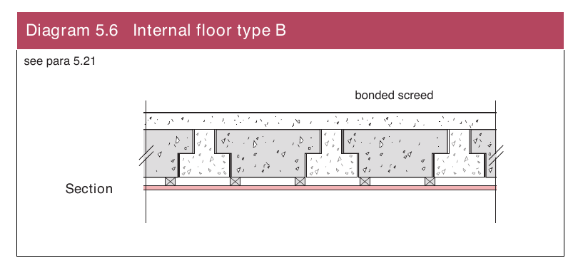
Note – Insulation against impact sounds can be improved by adding a soft floor finish such as a carpet.
Internal floor type C:
5.22Timber or metal joist, with woodbased board and plasterboard ceiling, and absorbent material (see Diagram 5.7) – floor surface of timber or woodbased board, minimum mass per unit area 15 kg/m2;
ceiling treatment of single layer of plasterboard, minimum mass per unit area 10 kg/m2, fixed using any normal fixing method;
an absorbent layer of mineral wool (minimum thickness 100 mm, minimum density 10 kg/m3) laid in the cavity.
Diagram 5.7 Internal floor type C
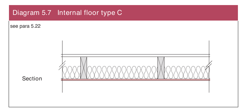
Note – Insulation against impact sounds can be improved by adding a soft floor finish such as a carpet.
General
#Source page 106
Section 6 Rooms for residential purposes
General
6.1Rooms for residential purposes are defined in Part A of the Building Regulations 2012.
6.2This Section gives examples of wall and floor types, which, if built correctly, should achieve the performance standards set out in Table 1b of the section entitled “Guidance Performance and introduction to provisions”. Precompletion testing will establish the compliance of the constructions built.
6.3The guidance in this section is not exhaustive and other designs, materials or products may be used to achieve the performance standards set out in Table 1b of the section entitled “Guidance Performance and introduction to provisions”. Advice should be sought from the manufacturer or other appropriate source.
Separating walls in new buildings containing rooms for residential purposes
6.4Of the separating walls described in Section 2 the following types are most suitable for use in new buildings containing rooms for residential purposes –
Wall type 1 – Solid masonry
Wall type 1.1, Dense aggregate concrete block, plaster on both room faces;
Wall type 1.2, Dense aggregate concrete in situ, plaster on both room faces;
Wall type 1.3, Brick, plaster on both room faces.
Note – Plasterboard may be used as an alternative wall finish, provided a sheet of minimum mass per unit area 10 kg/m2 is used on each room face.
Wall type 3 – Masonry between independent panels
Wall type 3.1, Solid masonry core (dense aggregate concrete block), independent panels on both room faces;
Wall type 3.2, Solid masonry core (lightweight concrete block), independent panels on both room faces.
Note – Wall types 2 and 4 can be used provided that care is taken to maintain isolation between the leaves. Specialist advice may be needed.
Corridor walls and doors
#Source page 107
6.5Separating walls described in 6.4 should be used between rooms for residential purposes and corridors in order to control flanking transmission and to provide the required sound insulation between the dwelling and the corridor. However, it is likely that the sound insulation will be reduced by the presence of a door.
6.6Ensure any door in a separating wall has good perimeter sealing (including the threshold where practical) and a minimum mass per unit area of 25 kg/m2. Alternatively, use a doorset with a minimum sound reduction index of 29 dB Rw (measured in the laboratory according to BS EN ISO 1403 and rated according to BS EN ISO 7171).
6.7Noisy parts of the building (e.g. function rooms or bars) should preferably have a lobby, double door or high performance doorset to contain the noise. Where this is not possible, nearby rooms for residential purposes should have a similar level of protection.
Separating floors in new buildings containing rooms for residential purposes
6.8Of the separating floors described in Section 3 the following types are most suitable for use in new buildings containing rooms for residential purposes:
Floor type 1. Concrete base with soft covering
Floor type 1.1C, Solid concrete slab (cast in situ, with or without permanent shuttering), soft floor covering (see para 3.28), ceiling treatment C;
Floor type 1.2B, Concrete planks (solid or hollow), soft floor covering
(see para 3.28), ceiling treatment B.
Note – Floor types 2 and 3 can be used provided that floating floors and ceilings are not continuous between rooms for residential purposes. Specialist advice may be needed.
Rooms for residential purposes resulting from material change of use
6.9It may be that an existing wall, floor or stair in a building that is to undergo material change of use will achieve the performance standards set out in Table 1b of the section entitled “Guidance Performance and introduction to provisions” without the need for remedial work. This would be the case if the construction was similar (including flanking constructions) to one of the constructions in paragraphs 6.4 and 6.8 (e.g. for solid walls and floors the mass requirement should be within 15% of the mass per unit area of a construction listed in the relevant section).
6.10For situations where it cannot be shown that the existing construction will achieve the performance standards set out in Table 1b of the section entitled “Guidance Performance and introduction to provisions”, Section 4 describes wall, floor and stair treatments to improve the level of sound insulation in dwellings formed by material change of use. These treatments may be used in buildings containing rooms for residential purposes. Specialist advice may be needed.
Junction details
#Source page 108
6.11In order for the construction to be fully effective, care should be taken to detail correctly the junctions between the separating wall and other elements, such as floors, roofs, external walls and internal walls.
6.12In the case of new buildings containing rooms for residential purposes, refer to the guidance in Sections 2 and 3 which describes the junction and flanking details for each of the new build separating wall and floor types.
6.13When rooms for residential purposes are formed by material change of use, refer to the notes and diagrams in Section 4 that describe the junction and flanking details for the wall and floor treatments.
6.14In the case of the junction between a solid masonry separating wall type 1 and the ceiling void and roof space, the solid wall need not be continuous to the underside of the structural floor or roof provided that –
(a)there is a ceiling consisting of two or more layers of plasterboard, of minimum total mass per unit area 20 kg/m2;
(b)there is a layer of mineral wool (minimum thickness 200 mm, minimum density 10 kg/m3) in the roof void; and
(c)the ceiling is not perforated. The ceiling joists and plasterboard sheets should not be continuous between rooms for residential purposes (see Diagram 6.1).
Diagram 6.1 Ceiling void and roof space
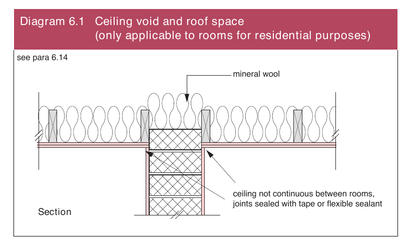
Room layout and building services design considerations
6.15Internal noise levels are affected by room layout, building services and sound insulation.
6.16The layout of rooms should be considered at the design stage to avoid placing noise sensitive rooms next to rooms in which noise is generated.
6.17Additional guidance is provided in BS 8233.
General
#Source page 109
Section 7 Reverberation in the common internal parts of buildings containing flats, maisonettes or rooms for residential purposes
General
7.1This Section describes how to determine the amount of additional absorption to be used in corridors, hallways, stairwells and entrance halls that give access to flats, maisonettes and rooms for residential purposes.
7.2For the purposes of this Section, a corridor or hallway is a space for which the ratio of the longest to the shortest floor dimension is greater than three.
7.3For the purposes of this Section, an entrance hall is a space for which the ratio of the longest to the shortest floor dimension is three or less.
7.4When an entrance hall, corridor, hallway or stairwell opens directly into another of these spaces, the guidance should be followed for each space individually.
7.5Two methods are described to satisfy regulation 51, Method A and Method B.
7.6Method A: Cover a specified area with an absorber of an appropriate class that has been rated according to BS EN ISO 11654.
7.7Method B: Determine the minimum amount of absorptive material using a calculation procedure in octave bands. Method B is intended only for corridors, hallways and entrance halls as it is not well suited to stairwells.
7.8Where additional guidance is required, specialist advice should be sought at an early stage.
Method A
7.9For entrance halls, corridors or hallways, cover an area equal to or greater than the floor area, with a Class C absorber or better. It will normally be convenient to cover the ceiling area with the additional absorption.
7.10For stairwells or a stair enclosure, calculate the combined area of the stair treads, the upper surface of the intermediate landings, the upper surface of the landings (excluding ground floor) and the ceiling area on the top floor. Either cover at least an area equal to this calculated area with a Class D absorber, or cover an area of at least 50% of this calculated area with a Class C absorber or better. The absorptive material should be equally distributed between all floor levels. It will normally be convenient to cover the underside of intermediate landings, the underside of the other landings, and the ceiling area on the top floor.
7.11Method A can generally be satisfied by the use of proprietary acoustic ceilings. However, the absorptive material can be applied to any surface that faces into the space.
Method B
#Source page 110
7.12In comparison with Method A, Method B takes account of the existing absorption provided by all surfaces. In some cases Method B should allow greater flexibility in meeting regulation 51 and require less additional absorption than Method A.
7.13For an absorptive material of surface area, S in m2, and sound absorption coefficient, αα,, the absorption area A is equal to the product of S and αα.
7.14The total absorption area, AT, in square metres is defined as the hypothetical area of a totally absorbing surface, which if it were the only absorbing element in the space would give the same reverberation time as the space under consideration.
7.15For n surfaces in a space, the total absorption area, AT, can be found using the following equation –
AT = αα1S1 + αα2S2 + ... + ααnSn
7.16For entrance halls, provide a minimum of 0.20 m2 total absorption area per cubic metre of the volume. The additional absorptive material should be distributed over the available surfaces.
7.17For corridors or hallways, provide a minimum of 0.25 m2 total absorption area per cubic metre of the volume. The additional absorptive material should be distributed over one or more of the surfaces.
7.18Absorption areas should be calculated for each octave band. Regulation 51 will be satisfied when the appropriate amount of absorption area is provided for each octave band between 250 Hz and 4000 Hz inclusively.
7.19Absorption coefficient data (to two decimal places) should be taken from the following –
(a)for specific products, use laboratory measurements of absorption coefficient data determined using BS EN 20354. The measured third octave band data should be converted to practical sound absorption coefficient data, ααp in octave bands, according to BS EN ISO 11654; or
(b)for generic materials, use Table 7.1. This contains typical absorption coefficient data for common materials used in buildings. These data may be supplemented by published octave band data for other generic materials.
7.20In Method B, each calculation step is to be rounded to two decimal places.
Report format
#Source page 111
Table 7.1 Absorption coefficient buildingsdata for common materialsin
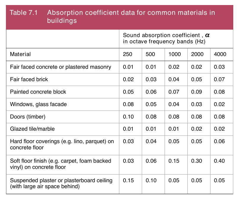
Report format
7.21Evidence that regulation 51 has been satisfied should be presented, (e.g. on a drawing or in a report), which should include –
(a)a description of the enclosed space (entrance hall, corridor, stairwell, etc.);
(b)the approach used to satisfy regulation 51, Method A or B –
(i)with Method A, state the absorber class and the area to be covered; or
(ii)with Method B, state the total absorption area of additional absorptive material used to satisfy the requirement; and
(c)Plans indicating the assignment of the absorptive material in the enclosed space.
Worked example
7.22Example: Entrance hall
The entrance hall has dimensions 3.0 m (width) x 4.0 m (length) x 2.5 m (height). The concrete floor is covered with carpet, the walls are painted concrete blocks and there are four timber doors (1.0 m x 2.4 m).
To satisfy regulation 51, either use –
(a)Method A: Cover at least 3.0 x 4.0 = 12 m2 with a Class C absorber or better; or
(b)Method B: Provide a minimum of 0.2 m2 absorption area per cubic metre of the volume.
Page 112
#Source page 112
| Table 7.2 Example calculation for an entrance hall (Method B) | ||||||
|---|---|---|---|---|---|---|
| Step 1 Calculate the surface area related to each absorptive material (i.e. for the floor, walls, doors and ceiling). | ||||||
| Surface | Surface finish | Area m² | ||||
| Floor Doors Walls (excluding door area) Ceiling | Carpet on concrete base Timber Concrete block, painted To be determined from this calculation | 12.00 9.60 25.40 12.00 | ||||
| Step 2 Obtain values of absorption coefficients for the carpet, painted concrete block walls and the timber doors. In this case, the values are taken from Table 7.1. | ||||||
| Absorption coefficient (αα) in octave frequency bands | ||||||
| Surface | Area m ² | 250 Hz | 500 Hz | 1000 Hz | 2000 Hz | 4000 Hz |
| Floor Doors Walls Ceiling | 12.00 9.60 25.40 12.00 | 0.03 0.10 0.05 To be determined | 0.06 0.08 0.06 from this calculati | 0.15 0.08 0.07 on | 0.30 0.08 0.09 | 0.40 0.08 0.08 |
| Step 3 Calculate the absorption area (m²) related to each absorption surface (i.e. for the floor, walls and doors) in octave frequency bands (Absorption area = surface area x absorption coefficient). | ||||||
| Absorption area (m²) | ||||||
| Surface | 250 Hz | 500 Hz | 1000 Hz | 2000 Hz | 4000 Hz | |
| Floor Doors Walls | 0.36 (12.0 x 0.03) 0.96 (9.60 x 0.10) 1.27 (25.40 x 0.05) | 0.72 0.77 1.52 | 1.80 0.77 1.78 | 3.60 0.77 2.29 | 4.80 0.77 2.03 | |
| Step 4 Calculate the sum of the absorption areas (m²) obtained in Step 3. | ||||||
| 250 Hz | 500 Hz | 1000 Hz | 2000 Hz | 4000 Hz | ||
| Total absorption area (m²) | 2.59 (0.36 + 0.96 +1.27) | 3.01 | 4.35 | 6.66 | 7.60 | |
| Step 5 Calculate the total absorption area (AT) required for the entrance hall. The volume is 30 m³ and therefore 0.20 x 30.0 = 6.00 m² of absorption area is required. | ||||||
| A (m²) T | 6.00 | |||||
| Step 6 Calculate additional absorption area (A) to be provided by ceiling (m²). If any values of minimum absorption area are negative, e.g. see 2000 Hz and 4000 Hz, then there is sufficient absorption from the other surfaces to meet the requirement without any additional absorption in this octave band: (Additional absorption = AT – total absorption area (from Step 5)). | ||||||
| 250 Hz | 500 Hz | 1000 Hz | 2000 Hz | 4000 Hz | ||
| Additional absorption area (m²) | 3.41 (6.00 – 2.59) | 2.99 | 1.65 | – 0.66 | – 1.60 | |
| N.B. Negative values indicate that no additional absorption is necessary. | ||||||
| Step 7 Calculate required absorption coefficient (αα) to be provided by ceiling: (Required absorption coefficient αα = Additional absorption area ÷ area of ceiling). | ||||||
| 250 Hz | 500 Hz | 1000 Hz | 2000 Hz | 4000 Hz | ||
| Required absorption coefficient (αα ) | 0.28 (3.41 ÷ 12.00) | 0.25 | 0.14 | Any value | Any value | |
| Step 8 Identify a ceiling product from manufacturer’s laboratory measurement data that provides absorption coefficients that exceed the values calculated in Step 7. |
Page 113
#Source page 113
7.23Method B is described in steps 1 to 8 in Table 7.2. In this example, the designer considers that covering the entire ceiling is a convenient way to provide the additional absorption. The aim of the calculation is to determine the absorption coefficient, ααceiling, needed for the entire ceiling.
7.24In this example, the absorption coefficients from Method B indicate that a Class D absorber could be used to cover the ceiling. This can be compared against the slightly higher absorption requirement of Method A, which would have used a Class C absorber or better to cover the ceiling.
A1 Wall mass
#Source page 114
Appendix A Method for calculating mass per unit area
A1 Wall mass
A1.1Where a mass is specified it is expressed as mass per unit area in kilograms per square metre (kg/m2).
A1.2The mass may be obtained from the manufacturer or it may be calculated by the method given in this Appendix. To calculate the mass per unit area of a masonry leaf use the formula below. This formula is not exact but is sufficient for this purpose.
A2 Formula for calculation of wall leaf mass per unit area
A2.1Mass per unit area of a brick/block leaf = mass of coordinating area / coordinating area
Mass per unit area of a brick/block leaf = Where Note – This formula provides the mass per unit area of the brick/block construction without surface finish. Note – See Diagram A.1 for block and mortar dimensions. MB is brick/block mass (kg) at the standard moisture content pm is density of mortar (kg/m3) at the standard moisture content T is the brick/block thickness without surface finish (m) d is mortar thickness (m) L is the co-ordinating length (m) H is the co-ordinating height (m) V is the volume of any frog/void filled with mortar (m3 ) Formula for calculation of wall leaf mass per unit area mass of co-ordinating area co-ordinating area MB + pm ( Td ( L + H - d ) + V ) LH = kg/m2
A2.2When calculating the mass per unit area for bricks and blocks use the density at the standard moisture content from Table 3.2, CIBSE Guide A (1999).
A2.3For cavity walls the mass per unit area of each leaf is calculated and added together.
A2.4Where surface finishes are used the mass per unit area of the finish is added to the mass per unit area of the wall.
Page 115
#Source page 115
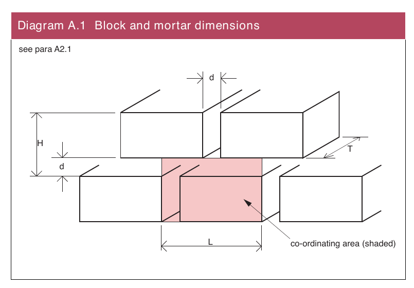
A3Simplified equations
A3.1Two examples are given (see Table A.1 and A.2) using the formula in A2.1. For each of these examples a simplified equation is obtained for that type of construction.
| Table A.1 Blocks laid flat for a wall thickness of 215 mm | |
|---|---|
| Example of single leaf wall, blocks laid flat | |
| d = 0.010 m T = 0.215 m L = 0.450 m H = 0.110 m V = 0 m³ p = 1800 kg/m³ m No surface finish Mass per unit area = (20.20 x M) + 43.00 kg/m² B Substituting for M in this formula gives the following values: B | |
| Block mass M (kg) B | Mass per unit area (kg/m²) |
| 6 | 164 |
| 8 | 205 |
| 10 | 245 |
| 12 | 285 |
| 14 | 326 |
| 16 | 366 |
| 18 | 407 |
| 20 | 447 |
Page 116
#Source page 116
| Table A.2 Blocks laid on edge for a wall thickness of 100 mm | ||
|---|---|---|
| Example of single leaf wall, blocks laid on edge | ||
| d = 0.010 m T = 0.100 m L = 0.450 m H = 0.225 m V = 0 m³ p = 1800 kg/m³ m No surface finish Single leaf wall: Mass per unit area = (9.90 x M ) + 11.80 kg/m² B Cavity wall: Mass per unit area = (19.80 x M ) + 23.60 kg/m² B Substituting for M in this formula gives the following values: B | ||
| Block mass M (kg) B | Mass per unit area (kg/m²) | |
| Single leaf | Cavity | |
| 6 | 71 | 142 |
| 8 | 91 | 182 |
| 10 | 111 | 222 |
| 12 | 131 | 261 |
| 14 | 150 | 301 |
| 16 | 170 | 340 |
| 18 | 190 | 380 |
| 20 | 210 | 420 |
A4Mass per unit area of surface finishes
A4.1The mass per unit area of surface finishes should be obtained from manufacturer's data.
A5Mass per unit area of floors
A5.1The mass of a solid and homogeneous floor (without hollows, beams or ribs) can be calculated from – where MF is mass per unit area of floor (kg/m 2 ) pc is density of concrete (kg/m 3 ) T is thickness of floor (m) MF = pc x T
Page 117
#Source page 117
A5.2The mass of a beam and block floor can be calculated from – where M F is the mass per unit area of floor (kg/m 2 ) Mblock, 1m is the mass of a 1m length of blocks (kg) LB is the distance between the beam centre lines i.e. the repetition interval (m) MF = LB M beam, 1m is the mass of a 1m length of beam (kg) ( Mbeam, 1m + Mblock,1m)
Note – See Diagram A.1 for block and mortar dimensions. Note – See Diagram A.2 for beam and block floor dimensions.
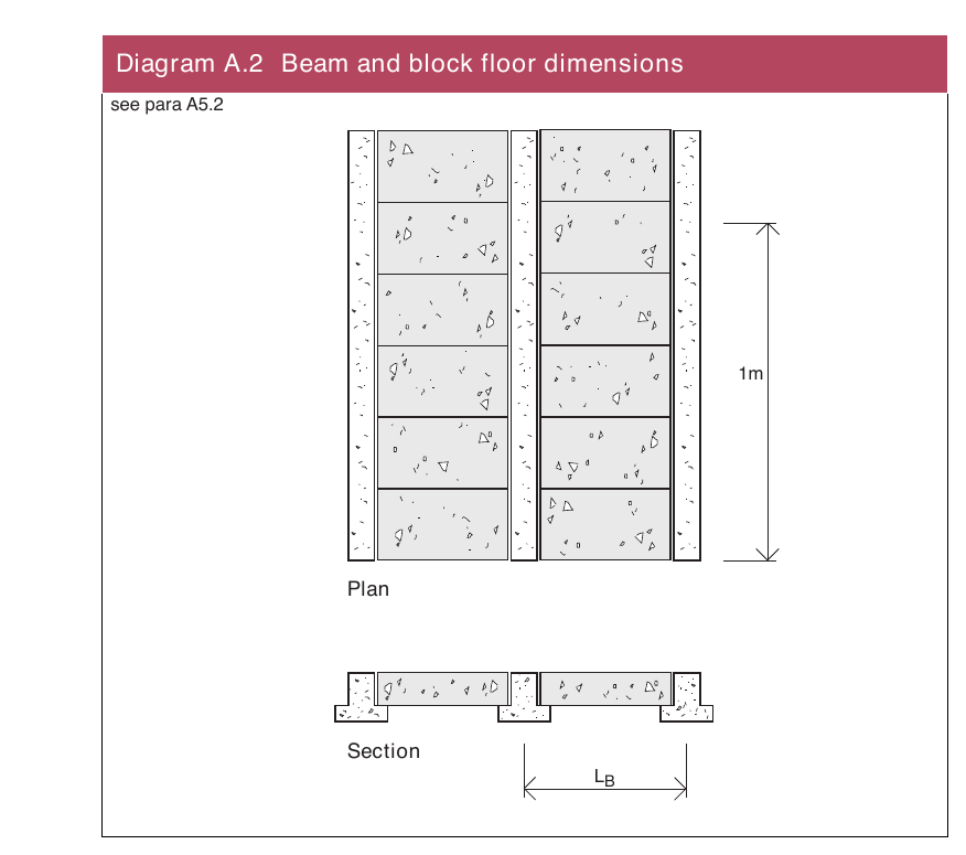
A5.3For other floor types (including floors with variable thickness), seek advice from the manufacturer on mass per unit area and performance.
Page 118
#Source page 118
Appendix B Procedures for sound insulation testing
B1Introduction
B1.1Section B.2 of this Appendix describes the sound insulation testing procedure approved by the Department. The approved procedure is that set out in Section B.2 and the Standards referred to in that Section.
B1.2Section B.3 of this Appendix provides guidance on laboratory testing in connection with achieving compliance with regulation 53 of the Building Regulations, and in connection with evaluation of components to be used in constructions subject to regulation 49.
B1.3Section B.4 of this Appendix gives guidance on test reports.
B1.4The person carrying out the building work should arrange for sound insulation testing to be carried out by a test body with appropriate third party accreditation. Test bodies conducting testing should preferably have UKAS accreditation (or a European equivalent) for field measurements. The Department also regards members of the ANC Registration Scheme as suitably qualified to carry out precompletion testing. The measurement instrumentation used should have a valid, traceable certificate of calibration, and should have been tested within the past two years.
B2Field measurement of sound insulation of separating walls and floors
Introduction
B2.1Sound insulation testing for the Building Regulations must be done in accordance with: BS EN ISO 1404; BS EN ISO 140 7; BS EN ISO 7171; BS EN ISO 717 2; BS EN 20354. When calculating sound insulation test results, no rounding should occur in any calculation until required by the relevant Standards, the BS EN ISO 140 series and the BS EN ISO 717 series.
Airborne sound insulation of a separating wall or floor
B2.2The airborne sound insulation of a separating wall or floor should be measured in accordance with BS EN ISO 1404. All measurements and calculations should be carried out using onethird octave frequency bands. Performance should be rated in terms of the weighted standardised level difference, DnT,w, and spectrum adaptation term, Ctr, in accordance with BS EN ISO 7171.
Measurements using a single sound source
B2.3For each source position, the average sound pressure level in the source and receiving rooms is measured in onethird octave bands using either fixed microphone positions (and averaging these values on an energy basis) or a moving microphone.
Measurements using multiple sound sources operating simultaneously
#Source page 119
For the source room measurements, the difference between the average sound pressure levels in adjacent onethird octave bands should be no more than 6 dB. If this condition is not met, the source spectrum should be adjusted and the source room measurement repeated. If the condition is met, the average sound pressure level in the receiving room, and hence a level difference, should be determined.
It is essential that all measurements made in the source and receiving rooms to determine a level difference should be made without moving the sound source or changing the output level of the sound source, once its spectrum has been correctly adjusted (where necessary).
The sound source should now be moved to the next position in the source room and the above procedure repeated to determine another level difference. At least two positions should be used for the source. The level differences obtained from each source position should be arithmetically averaged to determine the level difference, D as defined in BS EN ISO 1404.
Measurements using multiple sound sources operating simultaneously
For multiple sound sources operating simultaneously, the average sound pressure level in the source and receiving rooms is measured in onethird octave bands using either fixed microphone positions (and averaging these values on an energy basis) or a moving microphone.
For the source room measurements, the difference between the average sound pressure levels in adjacent onethird octave bands should be no more than 6 dB. If this condition is not met, the source spectrum should be adjusted and the source room measurement repeated. If the condition is met, determine the average level in the receiving room, and hence the level difference, D as defined in BS EN ISO 1404.
Impact sound transmission of a separating floor
The impact sound transmission of a separating floor should be measured in accordance with BS EN ISO 1407. All measurements and calculations should be carried out using onethird octave frequency bands. Performance should be rated in terms of the weighted standardised impact sound pressure level (L’nT,w) in accordance with BS EN ISO 7172.
Measurement of reverberation time
BS EN ISO 1404 and BS EN ISO 1407 refer to the ISO 354 (BS EN 20354) method for measuring reverberation time. However, for the approved procedure, the guidance in BS EN ISO 1407 relating to the source and microphone positions, and the number of decay measurements required, should be followed.
Room requirements
Section 1 gives guidance on the room types that should be used for testing. These rooms should have volumes of at least 25 m3. If this is not possible then the volumes of the rooms used for testing should be reported.
B2.4
B2.5
B2.6
B2.7
B2.8
B2.9
B2.10
B2.11
Tests between rooms
#Source page 120
B2.12Tests should be conducted in completed but unfurnished rooms or available spaces in the case of properties sold before fitting out; see Section 1.
B2.13Impact sound insulation tests should be conducted on a floor without a soft floor finish such as a carpet or foam backed vinyl except in the case of –
(a)separating floor type 1, as described in this Technical Booklet, or
(b)a concrete structural floor base which has a soft covering as an integral part of the floor.
B2.14If a soft covering has been installed on any other type of floor, it should be taken up. If that is not possible, at least half of the floor should be exposed and the tapping machine should be placed only on the exposed part of the floor.
B2.15When measuring airborne sound insulation between a pair of rooms of unequal volume, the sound source should be in the larger room.
B2.16Doors and windows should be closed.
B2.17Kitchen units, cupboards, etc. on all walls should have their doors open and be unfilled.
Measurement precision
B2.18Sound pressure levels should be measured to 0.1 dB precision.
B2.19Reverberation times should be measured to 0.01 s precision.
Measurements using a moving microphone
B2.20At least two positions should be used.
B2.21For measurements of reverberation time, discrete positions should be used rather than a moving microphone.
B3 Laboratory measurements
Introduction
B3.1Precompletion testing involves field testing on separating walls and floors (see Section 1 and Appendix B: B2). However, there are applications for laboratory tests to determine the performance of: floor coverings; floating floors; wall ties; resilient layers; internal walls and floors; and flanking laboratory tests to indicate the performance of novel constructions.
B3.2When calculating sound insulation test results, no rounding should occur in any calculation until required by the relevant Standards, i.e. the BS EN ISO 140 series and the BS EN ISO 717 series.
Tests on floor coverings and floating floors
B3.3Floor coverings and floating floors should be tested in accordance with BS EN ISO 1408: 1998 and rated in accordance with BS EN ISO 7172. The test floor should have a thickness of 140 mm.
Dynamic stiffness of resilient layers
#Source page 121
B3.4
B3.5
B3.6
B3.7
B3.8
B3.9
B3.10
B3.11
B3.12
It should be noted that text has been omitted from BS EN ISO 1408. For the purposes of this Technical Booklet, Section 6.2.1 of BS EN ISO 1408 should be disregarded, and Section 5.3.3 of BS EN ISO 1407, respectively, referred to instead.
BS EN ISO 1408 refers to the ISO 354 (BS EN 20354) method for measuring reverberation time, but the guidance in BS EN ISO 1408 relating to the source and microphone positions, and the number of decay measurements required, should be followed.
When assessing category II test specimens (as defined in BS EN ISO 1408) for use with separating floor type 2, the performance value (� .L w) should be achieved when the floating floor is both loaded and unloaded. The loaded measurements should use a uniformly distributed load of 2025 kg/m2 with at least one weight per square metre of the flooring area, as described in BS EN ISO 1408.
Dynamic stiffness of resilient layers
Dynamic stiffness of resilient layers should be measured in accordance with BS EN 290521. The test method using sinusoidal signals should be used. No precompression should be applied to the test specimens before the measurements.
Dynamic stiffness of wall ties
Dynamic stiffness of wall ties should be measured in accordance with BRE Information Paper IP 3/01.
Airborne sound insulation of internal wall and floor elements
The airborne sound insulation of internal wall or floor elements in a laboratory should be measured in accordance with BS EN ISO 140 3, and the performance rated in accordance with BS EN ISO 7171 to determine the weighted sound reduction index, Rw.
Measurements in a flanking laboratory
Tests of sound transmission in a flanking laboratory include both direct and flanking paths, and are a useful means of assessing the likely field performance of novel constructions.
It is not possible to demonstrate compliance using test results from a flanking laboratory.
Flanking laboratory: design
Construction details of a suitable laboratory can be obtained from the Acoustics Centre, BRE, Garston, Watford WD25 9XX.
Note – A CEN standard for the laboratory measurement of flanking transmission between adjoining rooms is currently under development.
Flanking laboratory: indicative airborne sound insulation values
#Source page 122
When a test construction has airborne sound insulation of at least 49 dB DnT,w + Ctr when measured in a flanking laboratory using the procedure given in Appendix B: B2, this can be taken as indicative that the same construction (i.e. identical in all significant details) may achieve at least 45 dB DnT,w + Ctr when built in the field (see paragraph B3.11).
Flanking laboratory: indicative impact sound insulation values
When a test construction has impact sound insulation no more than 58 dB L’ nT,w when measured in a flanking laboratory using the procedure given in Appendix B: B2, this can be taken as indicative that the same construction
(i.e. identical in all significant details) may achieve no more than 62 dB L’nT,w when built in the field (see paragraph B3.11).
Information to be included in test reports
Field test reports
Paragraph 1.42 of this Technical Booklet sets out the manner of recording the results of testing done.
Although not required, it may be useful to have a description of the building including –
(a)sketches showing the layout and dimensions of rooms tested;
(b)description of separating walls, external walls, separating floors, and internal walls and floors including details of materials used for their construction and finishes;
(c)mass per unit area in kg/m2 of separating walls, external walls, separating floors, and internal walls and floors;
(d)dimensions of any step and/or stagger between rooms tested; and
(e)dimensions and position of any windows or doors in external walls.
Laboratory test reports for internal walls and floors
Test reports should include the following information –
(a)Organisation conducting test, including –
(i)name and address;
(ii)third party accreditation number (e.g. UKAS or European equivalent); and
(iii)Name(s) of person(s) in charge of test.
(b)Name(s) of client(s).
(c)Date of test.
(d)Brief details of test, including –
(i)equipment; and
(ii)test procedures.
(e)Full details of the construction under test and the mounting conditions; and
B3.13
B3.14
B4
B4.1
B4.2
Page 123
#Source page 123
(f) Results of test shown in tabular and graphical form for onethird octave bands according to the relevant part of the BS EN ISO 140 series and BS EN ISO 717 series, including –
(i)singlenumber quantity and the spectrum adaptation terms; and
(ii)data from which the singlenumber quantity is calculated.
British Standards
#Source page 124
Appendix C Publications referred to
British Standards
BS EN ISO 1403: 1995 Acoustics. Measurement of sound insulation in buildings and of building elements. Laboratory measurement of airborne sound insulation of building elements.
AMD 15277 2005 (Also known as BS 27503: 1995).
BS EN ISO 1404: 1998 Acoustics. Measurement of sound insulation in buildings and of building elements. Field measurements of airborne sound insulation between rooms.
BS EN ISO 1406: 1998 Acoustics. Measurement of sound insulation in buildings and of building elements. Laboratory measurements of impact sound insulation of floors.
BS EN ISO 1407: 1998 Acoustics. Measurement of sound insulation in buildings and of building elements. Field measurements of impact sound insulation of floors.
BS EN ISO 1408: 1998 Acoustics. Measurement of sound insulation in buildings and of building elements. Laboratory measurements of the reduction of transmitted impact noise by floor coverings on a heavyweight standard floor.
BS EN ISO 7171: 1997 Acoustics. Rating of sound insulation in buildings and of building elements. Airborne sound insulation.
BS EN ISO 7172: 1997 Acoustics. Rating of sound insulation in buildings and of building elements. Impact sound insulation.
BS EN ISO 11654: 1997 Acoustics. Sound absorbers for use in buildings. Rating of sound absorption.
BS EN 8451: 2003 + A1: 2008 Specification for ancillary components for masonry. Ties tension straps, hangers and brackets. AMD 14736 2003
BS EN 1858: 2008 Chimneys. Components. Concrete flue blocks.
BS EN 20354: 1993 Acoustics. Measurement of sound absorption in a reverberation room. AMD 7781 1993, AMD 9974 1998
Withdrawn and superseded by BS EN ISO 354: 2003 Acoustics.
Measurement of Sound absorption in a reverberation room. AMD 14766 2003.
BS EN 290521: 1992 Acoustics. Method for the determination of dynamic stiffness. Materials used under floating floors in dwellings.
BS 56283: 2005 Code of practice for use of masonry. Materials and components, design and workmanship.
BS 8233: 1999 Sound Insulation and noise reduction for buildings. Code of practice.
CIBSE
#Source page 125
BRE
Information Paper IP 3/01 Dynamic stiffness of wall ties used in masonry cavity walls: measurement procedure, 2001. ISBN 1 86081 461 1
Information Paper IP 14/02 Dealing with poor sound insulation between new dwellings, 2002. ISBN 1 86081 549 0
Report BR 262 Thermal insulation: avoiding risks, 2002, ISBN 1 86081 515 4
CIBSE
Guide A Environmental design, 6th edition, 2006.
Department of Education for Northern Ireland (DENI)
Building Bulletin 93: Acoustic design of schools: A design guide, 2003. ISBN 9780112711056.
HSE
Workplace (Health, Safety and Welfare) Regulations (Northern Ireland) 1993.
Workplace Health, Safety and Welfare approved Code of Practice and Guidance, 1993. ISBN 0 337 11222 3.
Legislation Building Regulations (Northern Ireland) Order 1979 as amended Construction Products Regulations 1991, SI 1991/1620. Construction Products (Amendment) Regulations 1994, SI 1994/3051. Construction Products Directive (89/106/EEC). CE marking Directive (93/68/EEC).
Other publications
Technical Booklet B: 2012 – Materials and workmanship
Page 126
#Source page 126
Robust Details Ltd is a nonprofit distributing company, limited by guarantee, set up by the housebuilding industry. Its objectives are broadly to identify, arrange testing and, if satisfied, approve and publish design details that, if correctly implemented in separating structures, should achieve compliance with The Building Regulations (Northern Ireland) 2012 Part G. It also carries out checks on the performance achieved in practice. Compliance can also be demonstrated through the use of precompletion testing (see Section 1 and Appendix B) or a combination of Robust Details and precompletion testing. You can use both in combination if you so wish, however, precompletion testing is required for all constructions outside the Robust Details scheme.
Appendix D Design details approved by Robust Details Ltd
The robust design details are available in a handbook, which may be purchased from Robust Details Ltd. The company can be contacted at: Davy Avenue, Knowlhill, Milton Keynes, Bucks, MK5 8NB; telephone 0870 240 8210; fax 0870 240 8203; email administration@robustdetails.com; website www.robustdetails.com
Although the design details are in the public domain, their use in building work is not authorised unless the builder has registered the particular use of the relevant design detail or details with Robust Details Ltd and obtained a unique number or numbers from the company. Each unique number identifies a dwelling in which one or more of the design details are being used.
The system of unique numbers makes possible an essential part of Robust Details Ltd's procedures for ensuring that design details it has approved deliver reasonable sound insulation performance in practice. Robust Details Ltd carries out a programme of checks on a proportion of cases where approved design details are used.
The requirement for appropriate sound insulation testing does not apply to parts of the building which would otherwise be subject to the testing requirement where all the following apply –
(a)the building work consists of the erection of a new dwelling (i.e. a semidetached or terraced house) or a building containing flats and maisonettes;
(b)the person carrying out the building work notifies the district council before the start of building work on site that, in a specified part or parts of the building, he is using one or more specified design details from those approved by Robust Details Ltd. The notification must be given not later than the date on which notice of commencement and completion of certain stages of work of construction is given;
(c)the notification specifies the unique number or numbers issued by Robust Details Ltd in respect of the specified use of the design detail or details; and
(d)the building work carried out in respect of the part or parts of the building identified in the notification is in accordance with the design detail or details specified in the notification.
Page 127
#Source page 127
If the notification is late, or if it does not specify the relevant part or parts, the design detail or details in question and the unique number or numbers, the part or parts of the building in question are subject to sound insulation testing in the usual way.
If the notification is itself valid but the work is not carried out in accordance with the design detail or details, the relevant separating structures become subject to sound insulation testing. It would be open to the builder to take remedial action such that the district council body was satisfied that the work had been brought into compliance with the specified detail or details. With that exception, testing would be needed on all structures that have been subject to a valid notification but which in the opinion of the district council body have not then been constructed in accordance with the specified detail or details.
It should be noted that the compliance of work with a robust detail, in circumstances where the correct procedures have been followed to attract exemption from precompletion testing, is not a “deemed to satisfy” condition. The underlying requirement remains to achieve compliance with Part G. The guidance in Technical Booklet G is that compliance will usually be established by the measured performance of the structure. Therefore it would be open to anyone, e.g. a homeowner, who considered that a party structure does not comply with Part G, to seek to establish that by the carrying out of tests. It would not be a defence for the builder to claim that he had constructed the building using one or more design details approved by Robust Details Ltd if the structure's measured performance was shown not to meet the performance standards in this Technical Booklet.
Technical Booklets
#Source page 128
The following list comprises the series of Technical Booklets prepared by the Department for the purpose of providing practical guidance with respect to the technical requirements of the Building Regulations (Northern Ireland) 2012.
Technical Booklet B Materials and workmanship
Technical Booklet C Site preparation and resistance to contaminants and moisture Technical Booklet D Structure
Technical Booklet E Fire safety
Technical Booklet F1 Conservation of fuel and power in dwellings
Technical Booklet F2 Conservation of fuel and power in buildings other than dwellings Technical Booklet G Resistance to the passage of sound
Technical Booklet H Stairs, ramps, guarding and protection from impact Technical Booklet J Solid waste in buildings
Technical Booklet K Ventilation
Technical Booklet L Combustion appliances and fuel storage systems Technical Booklet N Drainage
Technical Booklet P Sanitary appliances, unvented hot water storage systems and reducing the risk of scalding Technical Booklet R Access to and use of buildings
Technical Booklet V Glazing
Any person who intends to demonstrate compliance with the Building Regulations by following the guidance given in a Technical Booklet is advised to ensure that the guidance is current on the date when the plans are deposited or notice given to the district council.