Northern Ireland Technical booklet K
Technical booklet K - Ventilation - October 2012
Library captured 10 September 2026 · Source updated 22 August 2026
● Finance and ● Personnel
#Source page 1
Department of
● Finance and ● Personnel
G u i d a n c e
Te c h n i c a l B o o k l e t
K
Ventilation
October 2012
Page 2
#Source page 2
Contents page
Introduction 3
Part K Regulations 6
Guidance Performance and introduction to provisions 8
Section 1 General 10
Definitions 10
Section 2 Ventilation of dwellings 19
NEW DWELLINGS 19
Method 1 – Ventilation rates 19
Method 2(i) – Ventilation systems for dwellings without basements 21
System 1 – Background ventilators and intermittent extract fans 23
System 2 – Passive stack ventilation (PSV) 28
System 3 – Continuous mechanical extract (MEV) 31
System 4 – Continuous mechanical supply and extract with heat recovery (MVHR) 34
Method 2(ii) – Ventilation systems for dwellings with basements 38
Method 3 – Other ventilation systems 39
EXISTING DWELLINGS 41
Section 3 Ventilation of new buildings other than dwellings 43
OFFICES 44
Method 1 – Ventilation rates 44
Method 2 – System guidance 46
Method 3 – Alternative approaches 47
Method 4 – Other ventilation systems 47
OTHER BUILDING TYPES 48
Section 4 Ventilation of replacement windows 52
Section 5 Ventilation of car parks 53
Page 3
#Source page 3
Appendix B Rapid ventilation 62
Appendix C Example calculations for ventilation sizing for dwellings 64
Appendix D Minimising ingress of external pollution into buildings in urban areas 73
Appendix E Publications referred to 76
Appendix A Performancebased ventilation
Technical Booklets
#Source page 4
Introduction
Technical Booklets
This Technical Booklet, which takes effect on 31st October 2012, is one of a series that has been prepared by the Department of Finance and Personnel (the Department) for the purpose of providing practical guidance with respect to the technical requirements of the Building Regulations (Northern Ireland) 2012 (the Building Regulations).
At the back of each Technical Booklet is a list of all the Technical Booklets that have been prepared and published by the Department for this purpose.
The guidance given in a Technical Booklet includes performance standards and design provisions relating to compliance with specific aspects of the Building Regulations for the more common building situations.
If the guidance in a Technical Booklet is followed there will be a presumption of compliance with the requirements of those Building Regulations covered by that guidance. However, this presumption can be overturned, so simply following the guidance does not guarantee compliance. For example, if a particular circumstance is not one of the more common building situations the design provisions given in the Technical Booklet may not be appropriate.
There are likely to be alternative ways of demonstrating compliance with the relevant requirements of the Building Regulations other than by following a design provision given in a Technical Booklet. There is therefore no obligation to adopt any particular provision set out in a Technical Booklet, should you decide to comply in some other way. However, you will have to demonstrate that your alternative solution meets the relevant requirements of the Building Regulations by those other means.
This Technical Booklet
Requirements
The guidance contained in this Technical Booklet relates only to the requirements of regulations 65, 66 and 68. The work will also have to comply with all other relevant requirements of the Building Regulations.
Materials and workmanship
Any building work which is subject to requirements imposed by Part A of the Building Regulations should be carried out in accordance with regulation 23 of those regulations. Guidance on meeting these requirements for materials and workmanship is given in Technical Booklet B which supports Part B.
The Building Regulations are made for specific purposes, primarily securing the health, safety, welfare and convenience of people and for the conservation of fuel and power. Standards and technical approvals are relevant guidance to the extent that they relate to these purposes. However, they may also address other aspects of performance such as serviceability, or aspects which although they relate to health and safety are not covered by the Building Regulations.
Named standards
#Source page 5
Where this Technical Booklet makes reference to a named standard, the relevant version of the standard is the one listed in Appendix E. However, if this version has been replaced or updated by the issuing standards body, the new version may be used as a source of guidance provided that it continues to address the relevant requirements of the Building Regulations.
Diagrams
The diagrams in this Technical Booklet supplement the text. They do not show all the details of construction and are not intended to illustrate compliance with any other requirement of the Building Regulations. They are not necessarily to scale and should not be used as working details.
Protected buildings
District councils have a duty to take account of the desirability to preserve the character of protected buildings when carrying out their functions under Building Regulations. Therefore, where work is to be carried out to a protected building to comply with Part K or any other Part of the Building Regulations, special consideration may be given to the extent of such work for compliance where it would unacceptably alter the character or appearance of the building. Protected buildings are defined in Article 3A(2) of the Building Regulations (Northern Ireland) Order 1979 (as amended).
Other legislation
The provisions of this Technical Booklet relate to the requirements of Building Regulations and do not include measures which may be necessary to meet the requirements of other legislation. Such other legislation may operate during the design or construction stages or when a building is brought into use and can extend to cover aspects which are outside the scope of the Building Regulations.
The Workplace (Health, Safety and Welfare) Regulations (Northern Ireland) 1993
The Workplace (Health, Safety and Welfare) Regulations (Northern Ireland) 1993 (the Workplace Regulations) contain some requirements which affect building design. The main requirements are now covered by the Building Regulations, but for further information see – The Workplace Regulations and the Workplace Health, Safety and Welfare Approved Code of Practice.
The Workplace Regulations apply to the common parts of flats and similar buildings if people such as cleaners, wardens and caretakers are employed to work in these common parts. Where the requirements of the Building Regulations that are covered by Part K do not apply to dwellings, the provisions may still be required in the situations described above in order to satisfy the Workplace Regulations.
The Air Quality Standards Regulations (Northern Ireland) 2010
#Source page 6
The Air Quality Standards Regulations (Northern Ireland) 2010 transpose EU Directive 2008/50/EC on ambient air quality and cleaner air for Europe and include certain provisions of Directive 2004/107/EC relating to arsenic, cadmium, mercury, nickel and polycyclic aromatic hydrocarbons in ambient air, and Council Decision 97/101/EC on the exchange of information.
The objective of this legislation is to ensure government takes appropriate steps to improve air quality by reducing the impact of air pollution on human health and ecosystems by setting standards for key pollutants, and provide air quality plans which demonstrate how air quality standards will be achieved and maintained. The government will make available to the public up to date information on a daily basis of recorded levels of pollutants and annual reports of results.
PART K
#Source page 7
Part K Regulations
Part K (comprising regulations 64 – 68) of the Building Regulations which sets out the requirements for the provision of ventilation of buildings, has been replicated below for the convenience of the user of this Technical Booklet and is taken directly from the Building Regulations (Northern Ireland) 2012.
Any person who intends to demonstrate compliance with the Building Regulations by following the guidance given in this Technical Booklet is advised to ensure that the regulations below are current on the date when plans are deposited or notices given to the district council.
As Part A (comprising regulations 1 – 21) of the Building Regulations sets out the interpretation along with the procedural requirements relating to the application of the regulations, the Department advises that all Parts of the Building Regulations be read in conjunction with Part A of those regulations.
The Building Regulations (Northern Ireland) 2012 and any subsequent amendment may be viewed by following the links from the Department’s website at “www.buildingregulationsni.gov.uk”.
PART K
Ventilation
Application
64.—(1) Regulation 65 shall not apply to a building or a space within a building which is used solely for storage or which is otherwise not intended for use by people.
(2)Regulations 65 and 66 shall not apply to a garage used solely in connection with a single dwelling.
(3)Regulation 65(2) shall not apply to the provision or extension of any fixed mechanical ventilation system or associated controls where testing and adjustment is not possible.
(4)Regulation 67(a) shall apply only to a dwelling being newly erected or created.
Means of ventilation
65.—(1) Adequate means of ventilation shall be provided for people in a building.
(2) Fixed mechanical ventilation systems and any associated controls shall be tested and commissioned to ensure that the requirement of paragraph (1) is met.
Ventilation of car parks
66.Adequate means of ventilation shall be provided for every space in a car park.
Notification of testing and commissioning
67.Where this regulation applies, the person carrying out the work, for the purpose of ensuring compliance with regulation 65(2), shall give, not more than 5 days after completion of the testing and commissioning, a notice in writing to the district council stating—
(a)the results of air flow tests; and
(b)that any fixed mechanical ventilation system and associated controls have been commissioned.
Provision of information
#Source page 8
68.Where regulation 65(1) applies, the person carrying out the work shall give, not more than 5 days after completion of the work, a notice in writing to—
(a)the building owner giving sufficient information about the buildings ventilation system and its maintenance requirements so that the building can be operated, maintained and ventilated in an efficient manner; and
(b)the district council stating that the requirements of subparagraph (a) have been met.
Relevant definitions in regulation 2 in Part A of the Building Regulations
“Garage”
Performance
#Source page 9
Guidance Performance and introduction to provisions
MEANS OF VENTILATION
Performance
0.1It is the view of the Department that the requirements of regulation 65 will be met where a ventilation system is provided that, under normal conditions, is capable of limiting, the accumulation of moisture which could lead to mould growth, and the accumulation of pollutants originating within a building which would otherwise become a hazard to the health of the people in the building. This is achieved by replacing “stale” indoor air from a building with “fresh” outside air.
0.2In general terms, the requirement may be achieved by providing a ventilation system which –
(a)extracts water vapour from areas where it is produced in significant quantities before it becomes widespread (e.g. kitchens, utility rooms and bathrooms);
(b)extracts pollutants which are a hazard to health from areas where they are produced in significant quantities before they become widespread,
•(e.g. rooms containing processes or activities which generate harmful contaminants);
(c)rapidly dilutes pollutants and water vapour produced in habitable and occupiable rooms and in sanitary accommodation, when necessary;
(d)makes available a minimum supply of outdoor air over long periods for the comfort of occupants and to disperse residual pollutants and water vapour when necessary. Such ventilation should minimise draughts, be reasonably secure, provide protection against rain penetration, limit the amount of heat lost and take account of heat recovery where appropriate;
(e)is designed, installed and commissioned to perform in a way that is not detrimental to the health of the people in the building; and
(f)is installed to facilitate maintenance where necessary.
0.3Ventilation is required for one or more of the following purposes –
(a)provision of outside air for breathing;
(b)dilution and removal of airborne pollutants, including odours;
(c)control of excess humidity (arising from water vapour in the indoor air); and
(d)provision of air for fuel burning appliances (which is controlled under Part L of the Building Regulations).
Airborne pollutants and water vapour include those released from materials and products used in the construction, decoration and furnishing of a building, and as a result of the activities of the building’s occupants. The numerical performance standards are given in Appendix A. Further information about control of emissions from construction products is available in BRE Digest 464.
Introduction to provisions in Section 2, 3 and 4
#Source page 10
0.4The guidance in Section 2 relates to the ventilation of new and existing dwellings. The Section is split into two parts, the first dealing with new dwellings with 3 ventilation methods suggested which if used would give the required levels of ventilation and the second dealing with providing adequate levels of ventilation to existing dwellings.
0.5The guidance in Section 3 relates to the ventilation of buildings other than dwellings. The Section is split into two parts, the first dealing specifically with offices with four ventilation methods suggested which if used would give the required levels of ventilation and the second, giving guidance documents which can be referred to for the other building types listed.
0.6The guidance in Section 4 relates to the replacement of windows to existing buildings.
VENTILATION OF CAR PARKS
Performance
0.7It is the view of the Department that the requirements of regulation 66 will be met by making adequate provisions of ventilation to extract pollutants which are hazardous to health from the area where they are produced in significant quanity before they become widespread. This can be done either by (a) natural ventilation or (b) mixed mode or (c) mechanical ventilation.
Introduction to provisions in Section 5
0.8The guidance in Section 5 relates to the natural ventilation, mixed mode and mechanical ventilation of car parks. In addition, it includes an alternative design approach which can be used if predicted pollutant levels are calculated.
NOTIFICATION OF TESTING AND COMMISSIONING AND PROVISION OF INFORMATION
Performance
0.9It is the view of the Department that the requirements of regulations 67 and 68 will be met where not more than 5 days after completion of the testing or commissioning sufficient information about the building ventilation system is provided to the building owner and where notice in writing of any mechanical ventilation commissioning and tests is given to the district council.
Introduction to provisions in Section 1
0.10Section 1 provides general guidance for Part K and additional guidance addressing the provision of information for dwellings in paragraph 1.28 and for the provision of information for buildings other than dwellings in paragraph 1.29.
DEFINITIONS
#Source page 11
Section 1 General
DEFINITIONS
1.1For the purposes of this Technical Booklet the following definitions apply –
Air permeability – the air leakage rate in cubic metres per hour per square metre of envelope area (m3/(h.m2)) at a pressure difference of 50 Pascals.
Air tightness – a general descriptive term for the resistance of the building envelope to infiltration with ventilators closed. The greater the air tightness at a given pressure difference across the envelope, the lower the infiltration.
Automatic control – where a ventilation device is opened and closed, switched on and off, or its performance adjusted by a mechanical or electronic controller which responds to a relevant stimulus. That stimulus is usually related to the humidity of the air in a room, pollutant levels
(e.g. carbon dioxide concentration in a room), occupancy of the space
(e.g. using a passive infrared motion detector) or pressure difference across the device (e.g. due to the wind outside).
•Background ventilation – is ventilation by means of a small ventilation opening designed to provide low rate controllable whole building ventilation
(e.g. a trickle ventilator), usually not less than 1.7 m above floor level. (See Diagram 1.1).
Basement (in relation to dwellings) – a dwelling, or a usable part of a dwelling (i.e. a habitable room) that is situated partly or entirely below ground level.
Bathroom – a room containing a bath or shower whether or not it also contains other sanitary appliances.
Cellar – part of a building that is situated partly or entirely below ground level and that is used solely for storage, heating plant or other purposes but not for habitation.
Closable opening – a ventilation opening which may be opened and closed under either manual or automatic control.
Common space – a space in a nondomestic building where people are expected to gather in large numbers such as shopping malls, foyers and similar common spaces but does not include spaces used solely for circulation.
Continuous operation – a mechanical ventilation device that runs all the time (e.g. mechanical extract ventilation (MEV) and mechanical ventilation with heat recovery (MVHR)). The air flow rate provided by the mechanical ventilation need not be constant but may be varied, under either manual or automatic control, in response to the demand for pollutant or water vapour removal.
Design air permeability – the value for air permeability selected by the designer for calculating the Dwelling carbon dioxide Emission Rate (DER).
Page 12
#Source page 12
District council – is defined in regulation 2 in Part A of the Building Regulations.
Domestic building – means a building or part of a building used for residential purposes such as a house, flat, maisonette, student accommodation, room for residential purposes or residential care premises but does not include a hotel, hostel or similar building where people reside only temporarily.
Dwelling – is defined in regulation 2 in Part A of the Building Regulations.
Equivalent area – a measure of the aerodynamic performance of a ventilator. It is the area of a sharpedged orifice which air would pass at the same volume flow rate, under an identical applied pressure difference, as the opening under consideration.
Extract ventilation – the removal of air directly from a space or spaces to outside. Extract ventilation may be by natural means (e.g. by passive stack ventilation) or by mechanical means (e.g. by an extract fan or central system).
Free area – the geometric open area of a ventilator.
Gross internal volume – the total internal volume of the heated space, including the volume of all furniture, internal walls, internal floors, etc.
Habitable room – is a room used for dwelling purposes but which is not solely a kitchen, utility room, bathroom, cellar or sanitary accommodation.
Infiltration – the uncontrolled exchange of air between inside a building and outside through cracks, porosity and other unintentional openings in a building, caused by pressure difference effects of the wind and/or stack effect.
Intermittent operation – a mechanical ventilator that does not run all the time, usually running only when there is a particular need to remove pollutants or water vapour (e.g. during cooking or bathing). Intermittent operation may be under either manual control or automatic control.
Manual control – where a ventilation device is opened and closed or switched on and off, or its performance is adjusted by the occupants of a room or building.
Mechanical extract ventilation – a system of ventilation operated by a power driven mechanism which extracts air from a room and discharges it only to the external air.
Nondomestic building – means a building or part of a building which is not a domestic building.
Occupiable room – a room in a building other than a dwelling that is occupied by people, such as an office, workroom, classroom, hotel bedroom, etc. but not a bathroom, sanitary accommodation, utility room or rooms or spaces used solely or principally for circulation, building services plant or storage purposes.
Page 13
#Source page 13
Passive stack ventilation (PSV) – a ventilation system using a duct from the ceiling of a room to a terminal on or above the roof, which operates by a combination of the natural stack effect (i.e. the movement of air due to the difference in temperature between the inside and outside) and the effect of wind passing over the terminal.
Permanent ventilation opening – a ventilation opening which is permanently fixed in the open position.
Rapid ventilation – ventilation by either natural means, using a large adjustable ventilation opening (e.g. a window) some part of which is not less than 1.75 m above floor level, or by mechanical means (e.g. a fan) and which allows the movement of a substantial volume of air in a short period of time.
Purposeprovided ventilation – that part of the ventilation of a building provided by ventilation devices designed into the building (e.g. via background ventilators, PSV, extract fans, mechanical ventilation or air conditioning systems).
Sanitary accommodation – is defined in regulation 84 in Part P of the Building Regulations.
Stack effect – the pressure differential between inside and outside a building caused by differences in the density of the air due to an indoor/outdoor temperature difference.
Surface water activity – a measure of the availability of water to micro organisms and is determined from the ratio of the vapour pressure of the water in the substrate to that of pure water at the same temperature and pressure. This ratio is in steadystate conditions numerically equal to the equilibrium relative humidity of the air except that the latter is commonly expressed as a percentage.
Utility room – a room used primarily for laundry purposes which may contain a sink, washing machine, tumble drier or similar moisture producing equipment and which is not entered solely from outside the building.
Ventilation – the supply and removal of air (by natural and/or mechanical means) to and from a space or spaces in a building. It normally comprises a combination of purpose provided ventilation and infiltration.
Ventilation opening – any part of a window, or any hinged panel, adjustable louvre or other means of ventilation which opens directly to the external air or to an enclosed place, but does not include any opening associated with a means of mechanical ventilation.
Wet room – a room used for domestic activities (e.g. such as cooking, clothes washing and bathing) which give rise to significant production of airborne moisture (e.g. a kitchen, utility room or bathroom). For the purposes of Part K, sanitary accommodation is regarded as a wet room.
Whole building ventilation (general ventilation) – nominally continuous ventilation of rooms or spaces at a relatively low rate to dilute and remove pollutants and water vapour not removed by the operation of extract ventilation, rapid ventilation or infiltration, as well as supplying outdoor air into the building. For an individual dwelling this is referred to as whole dwelling ventilation.
GENERAL
#Source page 14
Diagram 1.1 Provision for background ventilation
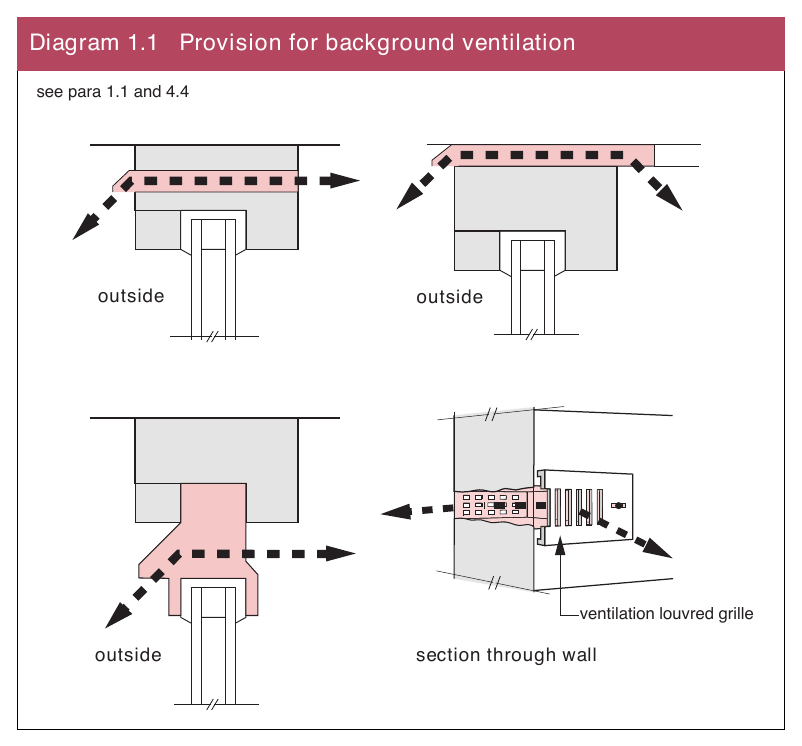
GENERAL
1.2The guidance in this Technical Booklet has not been formulated to deal with the products of tobacco smoking.
1.3Consideration should be given to the mitigation of ventilation energy use, where applicable, by employing heat recovery devices, efficient types of fan motors and/or energy saving control devices in the ventilation system.
1.4Exposure to house dust mite (HDM) allergens can lead to allergic sensitization and to exacerbation of allergic conditions. The moisture criteria needed to avoid HDM are more complex and demanding than those needed to avoid mould. The reduction of mite growth may be feasible in dwellings via appropriate ventilation, heating and moisture control as part of an integrated approach that involves the removal of existing mite allergens.
1.5It can be anticipated that there will be a continual trend towards more airtight buildings due to drivers for higher energy efficiency and lower carbon emissions. Through good design and construction, buildings can achieve an air permeability down to around 2 – 4 m3/(h.m2) of envelope area at 50 Pascal (Pa) pressure difference.
Page 15
#Source page 15
1.6
The ventilation provisions recommended for new dwellings in this Technical Booklet have been specified according to two standard designs of air permeability –
(a)in the default option, the guidance assumes no air permeability and therefore no infiltration, resulting in the building’s ventilation being reliant only on the installed ventilation provisions. This should provide adequate ventilation provisions for dwellings at all levels of air permeability and be particularly suitable when intending to construct a more airtight dwelling or where the person carrying out the building work does not have previous experience of closely matching design with asconstructed air permeability levels and therefore may achieve a significantly better performance than designed. If the building’s performance is likely to be substantially better than the design figure the default option should be used; and
(b)in the alternative option, the guidance assumes an infiltration of 0.15 air changes per hour (ach). The recommended ventilation provisions are therefore less than in option (a) as infiltration contributes to the total amount of ventilation required. This option is most appropriate when designing to an air permeability greater than 5 m3/(h.m2) at 50 Pa.
1.7Where a building contains both living accommodation and space to be used for commercial purposes (e.g. a workshop or office), the whole building should be treated as a dwelling as long as the commercial part could revert to domestic use.
1.8When constructing a dwelling as part of a larger building that contains other types of accommodation, Section 2 of this Technical Booklet should be used for guidance in relation to each individual dwelling. Section 3 gives guidance relating to the nondwelling parts of such buildings.
THE VENTILATION STRATEGY ADOPTED IN THIS TECHNICAL BOOKLET
1.9This Technical Booklet adopts the following strategy (systems that comply with the strategy are described in Sections 2 and 3) –
(a)using either intermittent or continuous extract ventilation from rooms where most water vapour and/or pollutants are generated to provide local control and minimise general spread to other areas
•(e.g. activities such as cooking, bathing or photocopying);
(b)calculating the whole building/dwelling ventilation requirement to provide fresh air to the building and to dilute and disperse residual water vapour and pollutants not dealt with by extract ventilation as well as removing water vapour and other pollutants that are released throughout the building (e.g. by building materials, furnishings, activities and the presence of occupants). Whole building/dwelling ventilation provides nominally continuous air exchange; and
Page 16
#Source page 16
(c)provide rapid ventilation throughout the building to aid removal of high concentrations of pollutants and water vapour released from occasional activities such as painting and decorating or accidental releases such as smoke from burnt food or spillage of water. (Rapid ventilation provisions may also be used to improve thermal comfort such as for summertime cooling, although this is not controlled under the Building Regulations).
1.10This ventilation strategy can be delivered by a natural ventilation system or a mechanical ventilation system or a combination of both (i.e. “a mixed mode” or “hybrid” ventilation system). For mainly naturally ventilated buildings, it is common to use a combination of ventilators to achieve this strategy (e.g. for dwellings it is common to use intermittent extract fans for extract ventilation, trickle ventilators for whole dwelling ventilation and windows for rapid ventilation). For mechanically ventilated or air conditioned buildings, it is common for the same ventilators to provide both local extract and whole building/dwelling ventilation and, for buildings other than dwellings, to provide rapid ventilation as well. Whilst it is not a requirement of the regulations, where fans are installed, it is advisable to fit antibackdraft shutters to the appliance.
PERFORMANCEBASED GUIDANCE
1.11This Technical Booklet focuses on performancebased guidance which suggests to the designer what level of ventilation should be sufficient, rather than how it should be achieved. Therefore, the designer has the freedom to use whatever ventilation provisions suit a particular building, including the use of innovative products and solutions, if it can be demonstrated that they meet the performance standard recommended in this Technical Booklet.
1.12The actual performance criteria for acceptable levels of moisture and pollutants are given in Appendix A. The air flow rates necessary to meet the performance criteria are given in Sections 2 and 3.
1.13Simple guidance in the form of ventilator sizes for the whole dwelling is also provided to make it easier for designers to meet building regulation requirements in common situations.
CONTROL OF VENTILATION
1.14Trickle ventilators are available which “throttle down” the ventilation flow according to the pressure difference across the ventilator so as to reduce draughts during windy weather.
1.15Other types of automatic control may be suitable for regulating ventilation devices (e.g. ventilation fans, dampers and air terminal devices) in dwellings. In such cases, it is important that the device controls the ventilation air supply and/or extract according to the need for ventilation in the space to remove or dilute indoor pollutants and water vapour. Trickle ventilators with automatic controls should also have manual override, so that the occupant can close the ventilator to avoid draughts and fully open the ventilator to provide maximum air flow when required. For pressure controlled trickle ventilators that are fully open at typical conditions (e.g. 1 Pa pressure difference), only a manual close option is recommended.
Page 17
#Source page 17
1.16Demandcontrolled ventilation systems use sensors to detect the level of occupancy, water vapour or other pollutants and adjust the ventilation rate to avoid overventilation. In dwellings, humiditycontrolled devices are available to regulate the humidity of the indoor air and, hence, minimise the risk of condensation and mould growth. In buildings other than dwellings more sophisticated automatic control systems are available. These may be based on sensors located within the building (e.g. occupancy sensors using local passive infrared detectors) or indoor carbon dioxide concentration sensors (using electronic carbon dioxide detectors) as an indicator of occupancy level and, therefore, body odour.
EQUIVALENT AREA OF VENTILATORS
1.17Equivalent area (instead of free area) is used in this Technical Booklet for the sizing of background ventilators (including trickle ventilators) because it is a better measure of the air flow performance of a ventilator. BS EN 131411 (Clause 4), includes a method of calculating the equivalent area of background ventilator openings.
1.18As equivalent area cannot be verified by physical measurement, it is preferable to use ventilators which have the equivalent area (measured in mm2 at 1 Pa pressure difference), or equivalent area per metre (where the equivalent area of the product varies according to length) marked on the product in a visible location. Where it is not practical for the manufacturer to mark the ventilator because it can be used in conjunction with a range of other components, some form of temporary marking for the installed system should be acceptable to the district council.
SUBASSEMBLIES AND PORTABLE BUILDINGS
1.19New buildings constructed from subassemblies must comply with all requirements in the Building Regulations. In some buildings constructed to have a planned time of use of less than two years, the provision of adequate ventilation may vary depending upon the particular circumstances. For example –
(a)a building created by dismantling, transporting and reerecting the subassemblies on the same premises would normally be considered adequate to meet the requirements of Part K; and
(b)a building constructed from subassemblies obtained from other premises or from stock manufactured before this Technical Booklet came into effect should normally be considered adequate to meet the requirements if it continues to satisfy the relevant requirements of the previous Part K.
1.20Portable buildings/subassemblies with a planned service life of greater than 2 years should comply with the ventilation requirements irrespective of how long they are located in a particular place.
Page 18
#Source page 18
INSTALLATION OF VENTILATION SYSTEMS
1.21In any building the priority should always be to provide ventilation through natural means before introducing mechanical ventilation to reach the required ventilation levels.
1.22The Domestic Ventilation Compliance Guide provides guidance on installing ventilation systems in new and existing dwellings. It also has a typical example of an installation checklist for the installer to complete and an inspection sheet for recording the testing and commissioning details.
1.23For buildings other than dwellings, guidance is provided in Section 3 of this Technical Booklet and includes references to other guidance publications.
AIR FLOW TESTING AND COMMISSIONING
1.24Where practicable and possible, all mechanical ventilation systems are to be commissioned and the dwelling air flow rates tested and results recorded. With some systems adjustment is not possible because the only controls are “on/off” switches, in such instances, e.g. stand alone extract fans, the manufacturer’s certification should be adequate.
1.25For dwellings, Sections 2 and 3 of the Domestic Ventilation Compliance Guide contain the procedures for measuring air flow rates and for the commissioning of mechanical systems. The guide also includes pro formas for recording the results in Section 5.
1.26For buildings other than dwellings, the procedure for commissioning ventilation systems is CIBSE Code M available from “www.cibse.org”.
PROVISION OF INFORMATION
1.27Information about how to operate the ventilation system and its maintenance requirements should be given to the building owner not more than 5 days after completion.
1.28For dwellings, the Domestic Ventilation Compliance Guide lists the documents which should be given to the building owner and includes samples of the inspection checklist and an air flow measurement test and commissioning record sheet, which should form part of the information pack.
1.29For buildings other than dwellings, CIBSE Code M available from “www.cibse.org” gives guidance on the procedures to follow and the documents for recording the results of testing and commissioning.
1.30The district council should be notified in writing, not more than 5 days after completion of the commissioning works, of the results of testing confirming that the testing and commissioning has been carried out and the system is operating adequately.
1.31Where the Domestic Ventilation Compliance Guide refers to Part F (Ventilation) of the building regulations for England & Wales and associated Approved Document F, it should be read as referring to the corresponding references in Part K (Ventilation) of the Building Regulations (Northern Ireland) 2012 and this Technical Booklet.
Page 19
#Source page 19
BUILDINGS OF HISTORIC OR ARCHITECTURAL MERIT
1.32Special considerations may apply where the building on which the work is to be carried out has historic or architectural merit and compliance with Part K of the Building Regulations would unacceptably alter the character or appearance of the building.
1.33When undertaking work on or in connection with a building of historic or architectural merit, the aim should be to follow the guidance in this Technical Booklet to the extent that it is practicable. Particular issues in relation to work in buildings that warrant sympathetic treatment and where specialist advice from conservation experts would be beneficial include –
(a)restoring the historic character of a building that has been subject to inappropriate alteration (e.g. replacement windows, doors and rooflights);
(b)rebuilding a building (e.g. following a fire or filling in a gap site in an historic terrace); and
(c)making provisions for the fabric of historic buildings to “breathe” to control moisture and long term decay problems.
NEW DWELLINGS
#Source page 20
Section 2 Ventilation of dwellings
GENERAL
2.1
This Section gives three methods of ventilating dwellings, by –
Method 1 – providing the ventilation rates set out in paragraphs 2.5 to 2.7; or
Method 2 – following the system guidance set out –
(i)for dwellings without basements (paragraphs 2.8 to 2.105); or
(ii)for dwellings with basements (paragraphs 2.106 to 2.108); or
Method 3 – using other ventilation systems (paragraph 2.109).
2.2There should be reasonable access provision for maintenance. This should include access for the purpose of changing filters, replacing defective components and cleaning duct work.
2.3Extract fans and ventilation systems lower the pressure in a building, which can cause the spillage of combustion products from openflued appliances. This can occur even if the appliance and the fan are in different rooms. Ceiling sweep fans produce air currents and hence local depressurisation which can also cause the spillage of flue gases from openflued gas appliances or from solid fuel open fires. In buildings where it is intended to install openflued combustion appliances and extract fans, the combustion appliance should be able to operate safely whether or not the fans are running. Refer to Part L, Combustion appliances and fuel storage systems.
NEW DWELLINGS
METHOD 1 – VENTILATION RATES
2.4The performance will be achieved by providing the air flow rates set out in paragraphs 2.5 to 2.7. The air flow rates specified are for the performance of the complete installation. The performance of the ventilation devices (and associated components such as ducting for fans) should be tested according to the standards listed under “Performance test methods” in paragraph 2.105. All natural and mechanical systems should be fully commissioned in accordance with the guidance given in the Domestic Ventilation Compliance Guide.
2.5
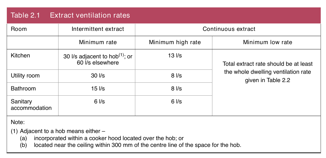
Extract ventilation to outside is required in each kitchen, utility room, bathroom and sanitary accommodation. The extract can be either intermittent or continuously operating. The intermittent rate and the minimum extract air flow rates at the highest and lowest settings for continuous systems, should be not less than that specified in Table 2.1.
Page 21
#Source page 21
Table 2.1 Extract ventilation rates
| Room | Intermittent extract | Continuous extract | |
|---|---|---|---|
| Minimum rate | Minimum high rate | Minimum low rate | |
| Kitchen | 30 l/s adjacent to hob(1); or 60 l/s elsewhere | 13 l/s | Total extract rate should be at least the whole dwelling ventilation rate given in Table 2.2 |
| Utility room | 30 l/s | 8 l/s | |
| Bathroom | 15 l/s | 8 l/s | |
| Sanitary accommodation | 6 l/s | 6 l/s | |
| Note: (1) Adjacent to a hob means either – (a) incorporated within a cooker hood located over the hob; or (b) located near the ceiling within 300 mm of the centre line of the space for the hob. |
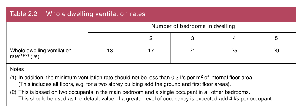
2.6The whole dwelling ventilation rate for the supply of air to the habitable rooms in a dwelling should be not less than that specified in Table 2.2.
2.7Rapid ventilation provision is required in each habitable room and should be capable of extracting a minimum of four air changes per hour (ach) per room directly to outside. In normal circumstances, openable windows or doors can provide this function in accordance with Appendix B. However where they cannot, a mechanical extract system should be provided. In other rooms (e.g. kitchens and bathrooms) the mechanical or passive stack extract provisions should provide adequate ventilation, although passive stack ventilation will take longer to purge the room.
Table 2.2 Whole dwelling ventilation rates
| Number of bedrooms in dwelling | |||||
|---|---|---|---|---|---|
| 1 | 2 | 3 | 4 | 5 | |
| Whole dwelling ventilation rate(1)(2) (l/s) | 13 | 17 | 21 | 25 | 29 |
| Notes: (1) In addition, the minimum ventilation rate should not be less than 0.3 l/s per m² of internal floor area. (This includes all floors, e.g. for a two storey building add the ground and first floor areas). (2) This is based on two occupants in the main bedroom and a single occupant in all other bedrooms. This should be used as the default value. If a greater level of occupancy is expected add 4 l/s per occupant. |
Page 22
#Source page 22
METHOD 2 (i) – VENTILATION SYSTEMS FOR DWELLINGS WITHOUT BASEMENTS
2.8The performance required for dwellings without basements could be achieved by following one of the four systems listed in paragraph 2.11. Worked examples for each system are given in Appendix C.
2.9For each system, guidance is given for dwellings to cover all design air permeabilities. Therefore, for ventilation purposes, it is not necessary for the asbuilt permeability to be close to the design permeability.
2.10In addition to this guidance, for each system, alternative guidance is provided for dwellings with asbuilt air permeabilities greater than 3 m3/(h.m2) at 50 Pa. It is recommended that this option is only selected if designing to an air permeability greater than 5 m3/(h.m2) at 50 Pa (e.g. such as 15 m3/(h.m2) at 50 Pa, allowed by Part F to avoid air pressure testing) and where the person carrying out the building work does not have previous experience of closely matching design with asbuilt air permeability levels. Where the alternative guidance is followed, and it is subsequently found that either –
(a)the tested air permeability for that dwelling is equal to or less than 3 m3/(h.m2) at 50 Pa, or
(b)where the dwelling is not tested, but another dwelling of the same dwelling type is tested and found to be equal to or less than 3 m3/(h.m2) at 50 Pa,
the district council using Part F guidance may require more air permeability testing to be carried out to ensure that all dwellings in the sample are provided with adequate ventilation provision.
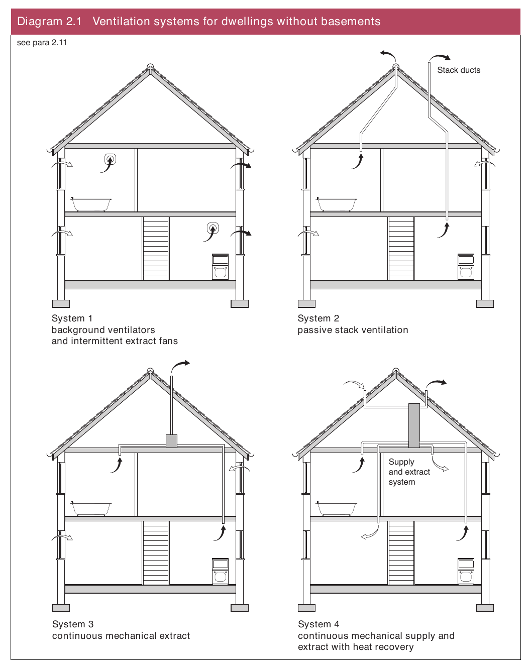
2.11Select one of the following four ventilation systems (see Diagram 2.1) –
System 1 – Background ventilators and intermittent extract fans. Guidance on minimum provisions for extract and whole dwelling ventilation is set out in paragraphs 2.12 to 2.40. Note that it includes separate guidance for dwellings with habitable rooms with only a single exposed façade.
System 2 – Passive stack ventilation (PSV). Guidance on minimum provisions for extract and whole dwelling ventilation is set out in paragraphs 2.41 to 2.64.
System 3 – Continuous mechanical extract (MEV). Guidance on minimum provisions for extract and whole dwelling ventilation is set out in paragraphs 2.65 to 2.84.
System 4 – Continuous mechanical supply and extract with heat recovery (MVHR). Guidance on minimum provisions for extract and whole dwelling ventilation is set out in paragraphs 2.85 to 2.104.
Page 23
#Source page 23
Diagram 2.1 Ventilation systems for dwellings without basements
Page 24
#Source page 24
System 1 – Background ventilators and intermittent extract fans
For additional information see worked examples C1 and C5 in Appendix C.
Design of System 1
2.12The background ventilators have been sized for the winter period. Additional ventilation may be required during warmer months and it has been assumed that the provisions for rapid ventilation (e.g. openable windows) will be used for this purpose.
Intermittent extract
2.13Intermittent extract rates are given in Table 2.1. For sanitary accommodation only, as an alternative, the rapid ventilation provisions (i.e. Windows) given in Appendix B can be used.
2.14Instead of a conventional intermittently used extract fan, a continuously running single room heat recovery ventilator could be used in wet rooms. It should use the minimum high rate given in Table 2.1 and 50% of this value as the minimum low rate. No background ventilator is required in the same room as the single room heat recovery ventilator. Furthermore, the total equivalent background ventilator area described in the tables below may be reduced by 2500 mm2 for each room containing a single room heat recovery ventilator.
Location of intermittent extract fans
2.15Intermittent extract fans should be installed in each wet room.
2.16Intermittent extract fans other than cooker hoods should be installed as high as is practicable and preferably within 400 mm of the ceiling.
2.17Cooker hoods should be 650 mm to 750 mm above the hob surface (or installed in accordance with the manufacturer’s instructions).
2.18Where fans and background ventilators are provided in the same room they should be a minimum of 500 mm apart.
Background ventilators
Follow Steps 1 to 3 –
Step 1 –
2.19Determine the total equivalent ventilator area see Table 2.3 for a dwelling with any design air permeability. As an alternative, the guidance in Table 2.4 may be followed for a dwelling designed to an air permeability greater than 5 m3/(h.m2) at 50 Pa which recommends less ventilation provisions, but see the guidance in paragraph 2.10.
Page 25
#Source page 25
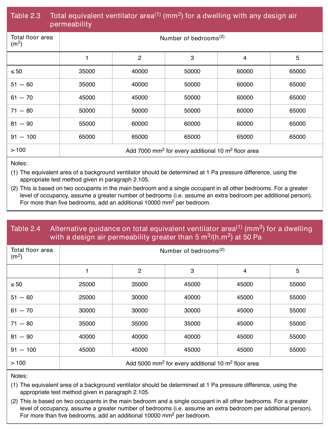
| Total floor area (m²) | Number of bedrooms(2) | ||||
|---|---|---|---|---|---|
| 1 | 2 | 3 | 4 | 5 | |
| ≤ 50 | 35000 | 40000 | 50000 | 60000 | 65000 |
| 51 — 60 | 35000 | 40000 | 50000 | 60000 | 65000 |
| 61 — 70 | 45000 | 45000 | 50000 | 60000 | 65000 |
| 71 — 80 | 50000 | 50000 | 50000 | 60000 | 65000 |
| 81 — 90 | 55000 | 60000 | 60000 | 60000 | 65000 |
| 91 — 100 | 65000 | 65000 | 65000 | 65000 | 65000 |
| > 100 | Add 7000 mm ² for every additional 10 m ² floor area | ||||
| Notes: (1) The equivalent area of a background ventilator should be determined at 1 Pa pressure difference, using the appropriate test method given in paragraph 2.105. (2) This is based on two occupants in the main bedroom and a single occupant in all other bedrooms. For a greater level of occupancy, assume a greater number of bedrooms (i.e. assume an extra bedroom per additional person). For more than five bedrooms, add an additional 10000 mm² per bedroom. |
| Total floor area (m²) | Number of bedrooms(2) | ||||
|---|---|---|---|---|---|
| 1 | 2 | 3 | 4 | 5 | |
| ≤ 50 | 25000 | 35000 | 45000 | 45000 | 55000 |
| 51 — 60 | 25000 | 30000 | 40000 | 45000 | 55000 |
| 61 — 70 | 30000 | 30000 | 30000 | 45000 | 55000 |
| 71 — 80 | 35000 | 35000 | 35000 | 45000 | 55000 |
| 81 — 90 | 40000 | 40000 | 40000 | 45000 | 55000 |
| 91 — 100 | 45000 | 45000 | 45000 | 45000 | 55000 |
| > 100 | Add 5000 mm ² for every additional 10 m ² floor area | ||||
| Notes: (1) The equivalent area of a background ventilator should be determined at 1 Pa pressure difference, using the appropriate test method given in paragraph 2.105. (2) This is based on two occupants in the main bedroom and a single occupant in all other bedrooms. For a greater level of occupancy, assume a greater number of bedrooms (i.e. assume an extra bedroom per additional person). For more than five bedrooms, add an additional 10000 mm ² per bedroom. |
Page 26
#Source page 26
Step 2 –
2.20Follow (a) or (b) as appropriate depending on the number of storeys –
(a)for multistorey dwellings, and single storey dwellings more than four storeys above ground level –
•use the total equivalent ventilator area from Step 1; or
(b)for single storey dwellings up to and including the fourth storey above
ground level – add a further 10000 mm2 to the total equivalent ventilator area from Step 1, preferably shared between several rooms.
Step 3 –
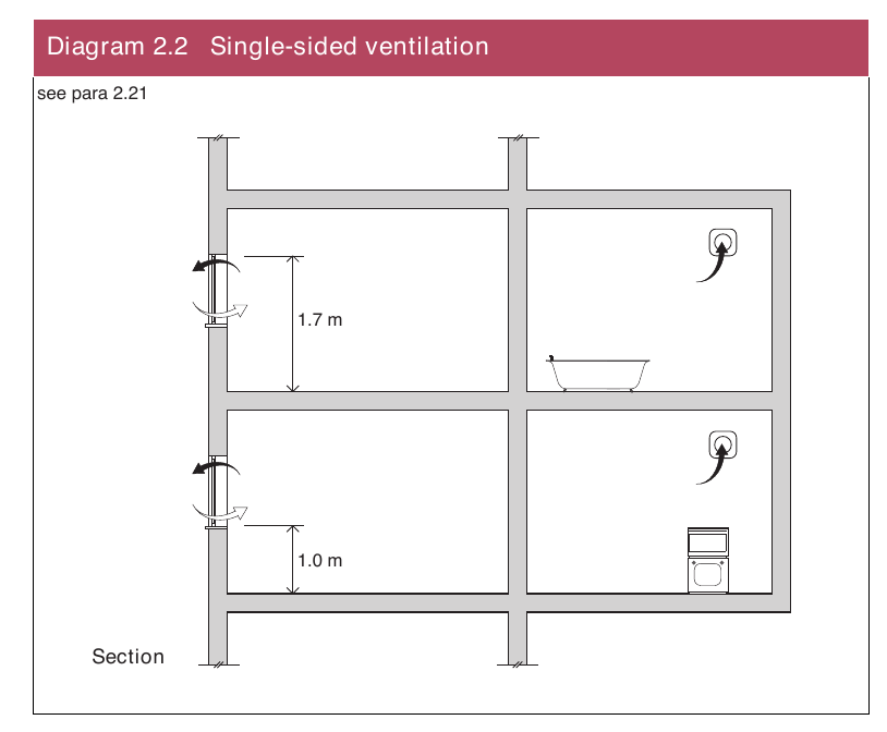
2.21For dwellings that have a single exposed façade, or at least 70% of the equivalent area is designed to be on the same façade, cross ventilation is not possible or is limited and therefore additional ventilation provisions are required. Background ventilators should be located at both high and low positions in the façade to provide enhanced singlesided ventilation.
The total equivalent area as described in Steps 1 and 2 should be provided at the high position (typically 1.7 m above floor level) for all dwelling types and all storey heights. In addition, ventilators having the same total equivalent area should be provided at least 1.0 m below the high ventilators as shown in Diagram 2.2.
2.22Singlesided ventilation is most effective where the dwelling is designed so that the habitable rooms are on the exposed façade, and these rooms are no greater than 6 m in depth.
Diagram 2.2 Singlesided ventilation
Page 27
#Source page 27
Location of background ventilators
2.23Background ventilators should be located to avoid draughts, typically 1.7 m above floor level (except in the singlesided case described in paragraph 2.21).
2.24Background ventilators should be located in all rooms with external walls, with at least 5000 mm2 equivalent area in each habitable room and 2500 mm2 equivalent area in each wet room. If a habitable room has no external walls the guidance in paragraphs 2.110 to 2.112 should be followed. If a wet room has no external walls the guidance for intermittent extract given for rapid ventilation and controls in paragraphs 2.27 to 2.33 should be followed.
2.25If the dwelling has more than one exposed façade, to maximise the air flow through the dwelling by encouraging cross ventilation, it is best to locate similar equivalent areas of background ventilators on opposite (or where this is not possible, adjacent) sides of the dwelling.
Rapid ventilation
2.26For each habitable room with –
(a)external walls, provide rapid ventilation as given in Appendix B for window or external door (including patio door) sizing; or
(b)no external walls, see paragraphs 2.110 to 2.112.
2.27For each wet room with –
(a)external walls, install an openable window (no minimum size); or
(b)no external walls, the normal extract provisions should suffice, although it will take longer to purge the room.
2.28There may be practical difficulties in achieving these provisions for habitable and wet rooms (e.g. if unable to open a window due to excessive noise from outside or where the window is fitted with opening restrictors). As an alternative a mechanical fan extracting at 4 ach to outside could be used. Any device used for rapid ventilation should be manually controlled. The location of the device is not critical for ventilation.
Air transfer
2.29To ensure good transfer of air throughout the dwelling, there should be an undercut of minimum area 7600 mm2 in all doors within the dwelling above the floor finish. For example, this is equivalent to an undercut of 10 mm for a standard 760 mm width door. This should be achieved by making an undercut of 10 mm above the fitted floor finish, or by a 20 mm undercut above the floorboards, or other surface, if the finish has not been fitted. For the purposes of this Guidance an external door is a door opening to the external air.
Controls
2.30Intermittent extract may be operated manually and/or automatically by a sensor (e.g. humidity, occupancy/usage, pollutant release). Humidity controls should not be used for sanitary accommodation as odour is the main pollutant.
Page 28
#Source page 28
2.31In kitchens, any automatic control must provide sufficient flow during cooking with fossil fuel (e.g. gas) to avoid the buildup of combustion byproducts.
2.32Any automatic control should have an override facility to allow the occupant to turn the extract on manually.
2.33In a room with no openable window (i.e. an internal room) an intermittent extract fan should have an overrun of at least 15 minutes except where it is controlled by a humidistat. In rooms with no natural light, the fans could be controlled by the operation of the main room light switch.
2.34Background ventilators may be either manually adjustable or automatically controlled.
2.35Where manual controls are provided, they should be within reasonable reach of the occupants. Where it is considered reasonable, pull cords, operating rods or similar devices should be provided.
Noise
2.36Whilst it is not a requirement of the regulations it is known that people will not use fans which are noisy therefore fans should be quiet so as not to discourage their use by occupants.
Noise from ventilation systems
2.37To ensure good acoustic conditions the average Aweighted sound pressure level in noise sensitive rooms, such as bedrooms and living rooms, should not exceed 30 dB L Aeq,T (see paragraph 2.38). In less sensitive rooms, such as kitchens and bathrooms, a higher level would be acceptable
(e.g. 35 dB LAeq,T). Noise from a continuously running mechanical ventilation system on its minimum low rate should not normally exceed these levels, and should preferably be lower in order to minimise the impact of the ventilation system.
2.38The main issues in minimising the noise impact of the ventilation system are the noise from the fan unit entering the ducts, the attenuation provided by the ducts, bends and junctions, and the characteristics of the room grill. The noise breaking out of the fan unit casing may also be significant in adjacent rooms. Whilst it is not a requirement of the regulations, reasonable provision should be made to limit the noise of mechanical extract fans.
The noise index L Aeq,T is used in BS 8233, where T is the duration of the measurement. If the noise from the sound source is steady
(e.g. fluctuating by up to 3 dB) a measuring time of 1 minute will be adequate and the L Aeq,1 min level will be similar to the dB(A) level used elsewhere. If the noise from the sound source fluctuates more than this a longer measuring time (T) will be required.
Environmental noise
2.39In order to minimise noise entering the building through the ventilation system, it may be appropriate to use sound attenuating ventilation products depending on the noise level and any imposed planning conditions.
Page 29
#Source page 29
Noise from the ventilation system may also disturb people who are outside the building, so externally emitted noise should also be considered, although it is not controlled under the Building Regulations.
Performance Tests
2.40The minimum performance requirements of the products chosen for System 1 should be measured in accordance with the test methods referred to in paragraph 2.105.
System 2 – Passive stack ventilation (PSV)
For additional information see worked examples C2 and C6 in Appendix C.
Design of System 2
2.41The background ventilators have been sized for the winter period. Additional ventilation may be required during warmer months and it has been assumed that the provisions for rapid ventilation (e.g. openable windows) will be used for this purpose.
2.42Ceiling extract grilles should have a free area of not less than the duct crosssectional area (when in the fully open position, if adjustable). The roof terminal design should be as specified by the passive stack ventilation (PSV) manufacturer.
2.43If a dwelling in which PSV is proposed is situated near a significantly taller building (i.e. more than 50% taller), it should be at least five times the difference in height away from the taller building (e.g. if the difference in height is 10 m, PSV should not be installed in a dwelling within 50 m of the taller building).
Size and location of PSV
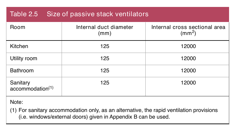
2.44For sizing of passive stack ventilators refer to Table 2.5. For a dwelling with only a single exposed façade, the dwelling should be designed such that the habitable rooms are on the exposed façade so as to achieve cross ventilation.
Table 2.5 Size of passive stack ventilators
| Room | Internal duct diameter (mm) | Internal cross sectional area (mm ²) |
|---|---|---|
| Kitchen | 125 | 12000 |
| Utility room | 125 | 12000 |
| Bathroom | 125 | 12000 |
| Sanitary accommodation(1) | 125 | 12000 |
| Note: (1) For sanitary accommodation only, as an alternative, the rapid ventilation provisions (i.e. windows/external doors) given in Appendix B can be used. |
Page 30
#Source page 30
2.45PSV extract terminals should be located in the ceiling or on a wall but should be not more than 400 mm below the ceiling.
2.46Instead of PSV, an openflued appliance may, when in operation, provide sufficient extract ventilation for the room in which it is located and can be arranged to provide sufficient ventilation when not firing. For instance, the provisions would be adequate where –
(a)a solid fuel openflued appliance provides the primary source of heating, cooking or hot water production; or
(b)an openflued appliance has a flue of free area at least equivalent to a 125 mm diameter duct and the appliance’s combustion air inlet and dilution inlet are permanently open, i.e. there is a path with no control dampers which could block the flow, or the ventilation path can be left open when the appliance is not in use (see also paragraph 2.3).
Background ventilators
Follow Steps 1 to 3 –
Step 1 –
2.47Determine the total equivalent ventilator area see Table 2.3 for a dwelling with any design air permeability. As an alternative, the guidance in Table 2.4 may be followed for a dwelling with a designed air permeability greater than 5 m3/(h.m2) at 50 Pa which recommends less ventilation provisions, but see the cautionary advice in paragraph 2.10.
Step 2 –
2.48Make an allowance for the total air flow through all PSV units. As an approximation assume each PSV unit provides an equivalent area of 3000 mm2.
Step 3 –
2.49The actual equivalent ventilator area required for the dwelling is the value found in Step 1 less that calculated from Step 2.
2.50In addition to this, the total equivalent area of the background ventilators must be at least equal to the total crosssectional area of all the PSV ducts.
Location of background ventilators
2.51Background ventilators should be located in all rooms with external walls except the rooms where a PSV is located, but openflued combustion appliances will still require an air supply to comply with Part L. There should be background ventilation of at least 5000 mm2 equivalent area in each habitable room and 2500 mm2 equivalent area in each wet room not containing a PSV.
2.52If a habitable room has no external walls, follow the guidance in paragraphs 2.110 to 2.112.
2.53Background ventilators should be located to avoid draughts, typically 1.7 m above floor level.
Page 31
#Source page 31
2.54If the dwelling has more than one exposed façade, to maximise the air flow through the dwelling by encouraging cross ventilation, it is best to locate similar equivalent areas of background ventilators on opposite (or where this is not possible, adjacent) sides of the dwelling.
Rapid ventilation
2.55For each habitable room with –
(a)external walls, provide rapid ventilation as given in Appendix B for window or external door (including patio door) sizing; or
(b)no external walls, see paragraphs 2.110 to 2.112.
2.56For each wet room with –
(a)external walls, install an openable window (no minimum size); or
(b)no external walls, the PSV system(s) will be adequate, although it will take longer to purge the room.
2.57There may be practical difficulties in achieving these provisions for habitable and wet rooms (e.g. if unable to open a window due to excessive noise from outside or where the window is fitted with opening restrictors). As an alternative a mechanical fan extracting at 4 ach to outside could be used. Any device used for rapid ventilation should be manually controlled. The location of the device is not critical for rapid ventilation.
Air transfer
2.58To ensure good transfer of air throughout the dwelling, there should be an undercut of minimum area 7600 mm2 in all doors within the dwelling above the floor finish. For example, this is equivalent to an undercut of 10 mm for a standard 760 mm width door. This should be achieved by making an undercut of 10 mm above the fitted floor finish, or by a 20 mm undercut above the floorboards, or other surface, if the finish has not been fitted. For the purposes of this Guidance an external door is a door opening to the external air.
Controls
2.59Controls should be set up to operate without occupant intervention and may use automatic controls with sensors for humidity, occupancy/usage and pollutant release. Humidity controls should not be used for sanitary accommodation as odour is the main pollutant.
2.60In kitchens, any automatic control must provide sufficient flow during cooking with fossil fuel (e.g. gas) to avoid the buildup of combustion by products.
2.61Ensure the system always provides the minimum whole dwelling ventilation rate specified in Table 2.2 for the heating season.
2.62Background ventilators may be either manually adjustable or automatically controlled.
2.63Where manual controls are provided, they should be within reasonable reach of the occupants. Where it is considered reasonable, pull cords, operating rods or similar devices should be provided.
Page 32
#Source page 32
Performance Tests
2.64Refer to paragraph 2.105 for test methods to measure the minimum performance requirements of the products chosen for System 2.
System 3 – Continuous mechanical extract (MEV)
For additional information see worked examples C3 and C7 in Appendix C.
Design of System 3
2.65The rates for continuous mechanical extract systems have been sized for the winter period. Additional ventilation may be required during warmer months and it has been assumed that the provisions for rapid ventilation
(e.g. openable windows) will be used for that purpose.
Step 1 –
2.66Determine the whole dwelling ventilation rate from Table 2.2.
No allowance is made for infiltration as the extract system lowers the pressure in the dwelling and any air flow via infiltration paths does not increase the overall ventilation rate.
Step 2 –
2.67Calculate the whole dwelling extract ventilation rate by adding the individual room rates for “minimum high rate” from Table 2.1.
For sanitary accommodation only, as an alternative, the rapid ventilation provisions given in Appendix B can be used. In this case the “minimum high rate” for the sanitary accommodation should be omitted from the Step 2 calculation.
Step 3 –
2.68The required extract rates are as follows –
(a)The maximum whole dwelling extract ventilation rate (i.e. the boost rate) should be at least the greater of Step 1 and Step 2.
•The maximum individual room extract rates should be not less than those given in Table 2.1 for minimum high rate.
(b)The minimum whole dwelling extract ventilation rate should be not less than the whole dwelling ventilation rate found in Step 1.
This system could comprise either a central extract system or individual room fans (or a combination of both). To ensure that the system provides the intended ventilation rate, measures should be taken to minimise likely wind effects when any extract terminal is located on the prevailing windward façade.
Possible solutions include ducting to another façade, use of constant volume flow rate units or, for central extract systems, follow more detailed guidance which has been prepared by the Energy Saving Trust (EST) and the Building Research Establishment (BRE) in conjunction with The Electric Heating and Ventilation Association (TEHVA) and the Residential Ventilation Association (RVA).
Page 33
#Source page 33
This guidance, entitled Performance Testing of Products for Residential Ventilation should be read in conjunction with the appropriate parts of BS EN 13141 and is available at the SAP Appendix Q website.
If a single room heat recovery ventilator (SRHRV) is used to ventilate a habitable room, with the rest of the dwelling provided by continuous mechanical extract, the air flow rates are determined as follows –
(i)determine the whole dwelling ventilation rate from Table 2.2;
(ii)calculate the room supply rate required for the SRHRV from –
Whole dwelling ventilation rate x Room volume
Total volume of all habitable rooms and
(iii) undertake Steps 1 to 3 above for sizing the continuous mechanical extract for the rest of the dwelling. However, when performing Step 1, the supply rate specified for the SRHRV should be subtracted from the value given in Table 2.2.
Background ventilators
2.69For any design air permeability, controllable background ventilators, having a minimum equivalent area of 2500 mm2, should be fitted in each room other than in rooms from which air is extracted. As an alternative, where the designed air permeability is greater than 5 m3/(h.m2) at 50 Pa background ventilators are not necessary, but see the cautionary advice in paragraph 2.10. Where this approach causes difficulties (e.g. on a noisy site) seek expert advice.
2.70Where background ventilators are fitted they should be –
(a)located to avoid draughts, typically 1.7 m above floor level;
(b)a minimum of 0.5 m away from fans fitted in the same room; and
(c)either manually adjustable or automatically controlled.
Rapid ventilation
2.71For each habitable room with –
(a)external walls, provide rapid ventilation as given in Appendix B for window or external door (including patio door) sizing; or
(b)no external walls, see paragraphs 2.110 to 2.112.
2.72For each wet room with –
(a)external walls, install an openable window (no minimum size); or
(b)no external walls, the normal extract provisions will suffice, although it will take longer to purge the room.
Page 34
#Source page 34
2.73There may be practical difficulties in achieving this (e.g. if unable to open a window due to excessive noise from outside or where the window is fitted with opening restrictors). In such situations, seek expert advice. As an alternative to the provisions given above for habitable and wet rooms, a mechanical fan extracting at 4 ach to outside could be used. Any device used for rapid ventilation should be manually controlled. The location of the device is not critical for rapid ventilation.
Location of ventilation devices
2.74Extract should be from each wet room.
2.75Cooker hoods should be 650 mm to 750 mm above the hob surface (or installed in accordance with the manufacturer instructions).
2.76Mechanical extract terminals and fans should be installed as high as is practical and preferably within 400 mm of the ceiling.
2.77Where ducts, etc. are provided in a dwelling with a protected stairway, precautions should be taken to avoid the possibility of the system allowing smoke or fire to spread into the stairway.
Air transfer
2.78To ensure good transfer of air throughout the dwelling, there should be an undercut of minimum area 7600 mm2 in all doors within the dwelling above the floor finish. For example, this is equivalent to an undercut of 10 mm for a standard 760 mm width door. This should be achieved by making an undercut of 10 mm above the fitted floor finish, or by a 20 mm undercut above the floorboards, or other surface, if the finish has not been fitted. For the purposes of this guidance an external door is a door opening to the external air.
Controls
2.79Controls should be set up to operate without occupant intervention, but may have manual or automatic controls to select the boost rate. Any manual boost controls should be provided locally to the spaces being served (e.g. bathrooms and kitchen), as provision of a single centrally located switch may result in fans being left in an inappropriate mode of operation. Automatic controls could include sensors for humidity, occupancy/usage or pollutant release. Humidity controls should not be used for sanitary accommodation as odour is the main pollutant.
2.80In kitchens, any automatic control must provide sufficient flow during cooking with fossil fuel (e.g. gas) to avoid the buildup of combustion byproducts.
2.81Ensure the system always provides the minimum whole dwelling ventilation rate specified in Table 2.2.
2.82Where manual controls are provided, they should be within reasonable reach of the occupants. Where it is considered reasonable, pull cords, operating rods or similar devices should be provided.
Page 35
#Source page 35
Noise
2.83Any continuously running fans should be quiet so as not to discourage their use by occupants. Guidance on noise is given in paragraphs 2.37 to 2.39.
Performance Tests
2.84Refer to paragraph 2.105 for test methods to measure the minimum performance requirements of the products chosen for System 3.
System 4 – Continuous mechanical supply and extract with heat recovery (MVHR)
For additional information see worked examples C4 and C8 in Appendix C.
Design of System 4
2.85System 4 has been sized for the winter period. Additional ventilation may be required during warmer months and it has been assumed that the provisions for rapid ventilation (e.g. openable windows) will be used for this purpose.
Step 1 –
2.86For any design air permeability, determine the whole dwelling ventilation supply rate from Table 2.2. As an alternative where the designed air permeability is intended to be greater than 5 m3/(h.m2) at 50 Pa, allow for infiltration for all dwelling types by subtracting from the whole dwelling ventilation supply rate from Table 2.2 –
0.04l/(s.m3) x gross internal volume of the dwelling heated space (m3), but see the cautionary advice in paragraph 2.10.
To make the most efficient use of the MVHR system the designed air permeability should be in the range 2 – 4 m3/(h.m2) at 50 Pa.
Step 2 –
2.87Calculate the whole dwelling extract ventilation rate by adding the individual room rates for “minimum high rate” from Table 2.1.
For sanitary accommodation only, as an alternative, the rapid ventilation provisions given in Appendix B can be used. In this case the “minimum high rate” for sanitary accommodation should be omitted from the Step 2 calculation.
Step 3 –
2.88The required air flow rates are as follows –
(a)The maximum whole dwelling extract ventilation rate (i.e. the boost rate) should be at least the greater of Step 1 and Step 2. The maximum individual room extract rates should be not less than those given in Table 2.1 for “minimum high rate”; and
(b)The minimum whole dwelling supply ventilation rate should be not less than the whole dwelling ventilation rate found in Step 1.
Page 36
#Source page 36
Rapid ventilation
2.89For each habitable room –
(a)with external walls, provide rapid ventilation as given in Appendix B for window or external door (including patio door) sizing; or
(b)without external walls, see paragraphs 2.110 to 2.112.
2.90For each wet room –
(a)with external walls, install an openable window (no minimum size); or
(b)without external walls, the normal extract provisions will suffice, although it will take longer to purge the room.
2.91There may be practical difficulties in achieving this (e.g. if unable to open a window due to excessive noise from outside or where the window is fitted with opening restrictors). In such situations, seek expert advice. As an alternative to the provisions given above for habitable and wet rooms, a mechanical fan extracting at 4 ach to outside could be used. Any device used for rapid ventilation should be manually controlled. The location of the device is not critical for rapid ventilation.
Location of ventilation devices
2.92Extract should be from each wet room. Air should normally be supplied to each habitable room. The total supply air flow should normally be distributed in proportion to the habitable room volumes. Recirculation by the system of moist air from the wet rooms to the habitable rooms should be avoided.
2.93Where an extract cooker hood is provided as part of the MVHR system, it should be located 650 mm to 750 mm above the hob surface (or installed in accordance with the manufacturer’s instructions).
2.94Mechanical extract terminals and fans should be installed as high as is practical and preferably within 400 mm of the ceiling.
2.95Mechanical supply terminals should be located and directed to avoid draughts.
2.96Where ducts, etc. are provided in a dwelling with a protected stairway, precautions may be necessary to avoid the possibility of the system allowing smoke or fire to spread into the stairway.
2.97Background ventilators are not required with System 4.
Air transfer
2.98To ensure good transfer of air throughout the dwelling, there should be an undercut of minimum area 7600 mm2 in all doors within the dwelling above the floor finish. For example, this is equivalent to an undercut of 10 mm for a standard 760 mm width door. This should be achieved by making an undercut of 10 mm above the fitted floor finish, or by a 20 mm undercut above the floorboards, or other surface, if the finish has not been fitted. For the purposes of this guidance an external door is a door opening to the external air.
Page 37
#Source page 37
Controls
2.99Controls should be set up to operate without occupant intervention, but may have manual or automatic controls to select the boost rate. Any manual boost controls should be provided locally to the spaces being served
(e.g. bathrooms and kitchen), as provision of a single centrally located switch may result in fans being left in an inappropriate mode of operation. Automatic controls could include sensors for humidity, occupancy/usage, pollutant release. Humidity controls should not be used for sanitary accommodation as odour is the main pollutant.
2.100In kitchens, any automatic control must provide sufficient flow during cooking with fossil fuel (e.g. gas) to avoid the buildup of combustion byproducts.
2.101Ensure the system always provides the minimum whole dwelling ventilation rate specified in Table 2.2.
2.102Where manual controls are provided, they should be within reasonable reach of the occupants. Where it is considered reasonable, pull cords, operating rods or similar devices should be provided.
Noise
2.103All continuously running fans used should be quiet so as not to discourage their use by occupants. Guidance on noise is given in paragraphs 2.37 to 2.39.
Performance Tests
2.104Refer to paragraph 2.105 for test methods to measure the minimum performance requirements of the products chosen for System 4.
Performance test methods
2.105The minimum performance requirements specified in Systems 1 to 4 for each ventilator, should be measured using the test methods contained in the relevant clauses of the following documents –
(a)Intermittent extract fans
•BS EN 131414 Clause 4 “Performance testing of aerodynamic characteristics”. All subclauses are relevant.
(b)Range hoods
•BS EN 131413 Clause 4 “Performance testing of aerodynamic characteristics”. All subclauses are relevant.
(c)Background ventilators (nonRelative Humidity (RH) controlled)
BS EN 131411 Clause 4 “Performance testing of aerodynamic characteristics”. Only the following subclauses are relevant –
(i)4.1 “Flow rate/pressure”; and
(ii)4.2 “Nonreverse flow ability”.
Page 38
#Source page 38
The performance requirement should normally be met for both air flow from outside to inside the dwelling and for inside to outside. To ensure the installed performance of background ventilators is similar to the results achieved when they are tested to this Standard, background ventilators and associated components should be installed according to manufacturer’s instructions. This also applies to nonRelative Humidity controlled soundattenuating background ventilators.
(d)Passive stack ventilators
•For the commissioning of passive stack systems follow the guidance in Domestic Ventilation Compliance Guide.
(e)Continuous mechanical extract (MEV) systems
BS EN 131416 Clause 4 “Performance testing of aerodynamic characteristics”. See Note 2 below.
(f)Continuous supply and extract ventilation MVHR units BS EN 131417 Clause 6 “Test methods”. See Note 2.
(g)Single room heat recovery ventilators
BS EN 131418 Clause 6 “Test methods”. Only the following subclauses are relevant:
(i)6.1 “General”; and
(ii)6.2 “Performance testing of aerodynamic characteristics” subclauses 6.2.1 “Leakages and mixing” and 6.2.2 “Air flow”.
For internal and external leakage and for mixing, the unit should meet at least Class U4 given in Clause 3.2 “Classification”.
Note 1 – For all ventilation devices (e.g. extract fan, cooker hood), fitting ducting, intake/exhaust terminals, filters etc. will impose an additional resistance to the air flow. Where appropriate this should be allowed for when specifying ventilation system components because, e.g. a fan that meets the appropriate requirements when tested on its own may fail to meet the requirement when it is installed and connected to ducting etc. In such cases, the performance of the separate components should be measured according to the relevant parts of BS EN 13141 and other relevant standards. The complete assembly, as installed, should be designed to meet the performance requirement by following good practice such as is given in the Domestic Ventilation Compliance Guide.
Note 2 – Detailed guidance on the tests to be undertaken has been prepared by the Energy Saving Trust (EST) and the Building Research Establishment (BRE) in conjunction with The Electric Heating and Ventilation Association (TEHVA) and the Residential Ventilation Association (RVA). This guidance, entitled Performance Testing of Products for Residential Ventilation should be read in conjunction with the appropriate parts of BS EN 13141 and is available at the SAP Appendix Q website.
Page 39
#Source page 39
METHOD 2 (ii) – VENTILATION SYSTEMS FOR DWELLINGS WITH BASEMENTS
2.106For a dwelling which includes a basement that is connected to the rest of the dwelling above ground by a large permanent opening (e.g. an open stairway), the whole dwelling including the basement should be ventilated in accordance with paragraph 2.8 (for dwellings without basements) and treated as a multistorey dwelling. If the basement has only a single exposed façade, while the rest of the dwelling above ground has more than one exposed façade, ventilation systems 3 and 4 are preferred, following the guidance in paragraph 2.8. If systems 1 or 2 are to be used, seek expert advice.
2.107For a dwelling which includes a basement that is not connected to the rest of the dwelling above ground by a large permanent opening –
(a)the part of the dwelling above ground should be considered separately and ventilated in accordance with paragraph 2.8. If the part of the dwelling above ground has no bedrooms, assume it has one bedroom for the purpose of determining ventilation provisions; and
(b)the basement should be treated separately as a singlestorey dwelling above ground in accordance with paragraph 2.8. If the basement has no bedrooms, assume it has one bedroom for the purpose of determining ventilation provisions. The guidance on natural ventilation given in this Technical Booklet may not be appropriate for this situation and expert advice should be sought.
2.108For a dwelling which comprises only a basement it should be treated as a singlestorey dwelling above ground in accordance with paragraph 2.8. The guidance on natural ventilation given in this Technical Booklet may not be appropriate for this situation and expert advice should be sought.
Page 40
#Source page 40
METHOD 3 – OTHER VENTILATION SYSTEMS
2.109An alternative ventilation system can be used, provided it can be demonstrated to the district council that it satisfies Part K, e.g. by showing that it meets the moisture and performancebased ventilation requirements in Appendix A.
VENTILATION OF A HABITABLE ROOM THROUGH ANOTHER HABITABLE ROOM OR A CONSERVATORY
2.110In a habitable room not containing openable windows (i.e. an internal room) the regulation should be met if the room is either ventilated through another habitable room (see paragraph 2.111) or through a conservatory (see paragraph 2.112).
2.111A habitable room not containing openable windows may be ventilated through another habitable room (see Diagram 2.3) where –
(a)there is, from the habitable rooms to outside, provision for both –
(i)rapid ventilation through one or more ventilation openings, with a total area given in Appendix B based on at least the combined floor area of the habitable rooms; and
(ii)background ventilation, of at least 8000 mm2 equivalent area; and
(b)there is an area of permanent opening between the two rooms given in Diagram 2.3 based on at least the combined floor area of the habitable rooms.
Diagram 2.3 Two habitable rooms treated as a single room for ventilation purposes
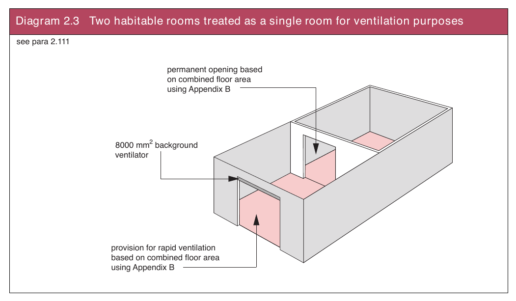
Page 41
#Source page 41
2.112A habitable room not containing openable windows may be ventilated through a conservatory (see Diagram 2.4) where –
(a)there is, from the conservatory to outside, provisions for both –
(i)rapid ventilation through one or more ventilation openings, with a total area given in Appendix B based on at least the combined floor area of the habitable room and conservatory; and
(ii)background ventilation, a ventilation opening (or openings) of at least 8000 mm2 equivalent area; and
(b)there are openings (which must be closable) between the habitable room and the conservatory for –
(i)rapid ventilation equivalent to paragraph 2.112(a)(i) above; and
(ii)background ventilation equivalent to paragraph 2.112(a)(ii) above which should be typically located at least 1.7 m above floor level and need not be within the door frame.
Diagram 2.4 A habitable room ventilated through a conservatory
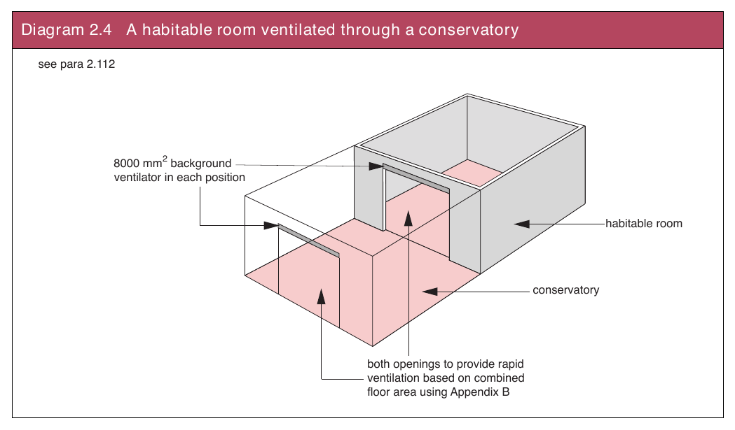
EXISTING DWELLINGS
#Source page 42
ADDITION OF A HABITABLE ROOM (NOT INCLUDING A CONSERVATORY) TO AN EXISTING DWELLING
2.113The requirements should be met by following the guidance in paragraphs
2.114to 2.116.
2.114The general ventilation rate for the additional room and, if necessary, adjoining rooms should be achieved by one of the following options –
(a)background ventilators should be used as follows –
(i)if the additional room is connected to an existing habitable room which now has no windows opening to outside, the guidance in paragraph 2.111 should be followed; or
(ii)if the additional room is connected to an existing habitable room which still has windows opening to outside but with a total background ventilator equivalent area less than 5000 mm2, the guidance in paragraph 2.111 should be followed; or
(iii)if the additional room is connected to an existing habitable room which still has windows opening to outside and with a total background ventilator equivalent area of at least 5000 mm2, there should be background ventilators of at least 8000 mm2 equivalent area between the two rooms and background ventilators of at least 8000 mm2 equivalent area between the additional room and outside; or
(b)a single room heat recovery ventilator should be used to ventilate the additional habitable room. The supply rate to that room should be determined as follows. First, determine the whole building ventilation rate from Table 2.2. Second, calculate the room supply rate required from the formula –
Whole dwelling ventilation rate x Room volume
Total volume of all habitable rooms
2.115For rapid ventilation, follow the guidance given in paragraph 2.26.
2.116Guidance on location is given in paragraphs 2.23 to 2.25 and controls is given in paragraphs 2.30 to 2.35. Guidance on performance testing standards is given in paragraph 2.105.
ADDITION OF A WET ROOM TO AN EXISTING DWELLING
2.117The requirements for the addition of a wet room should be met by following the guidance in paragraphs 2.118 to 2.121.
2.118Whole building and extract ventilation can be provided by –
(a)intermittent extract, as given in paragraph 2.13, and a background ventilator of at least 2500 mm2 equivalent area; or
(b)single room heat recovery ventilator, as given in paragraph 2.14; or
(c)passive stack ventilator, as given in Table 2.5; or
Page 43
#Source page 43
(d)continuous extract fan, as given in paragraphs 2.66 to 2.68; or
(e)extending an existing MVHR system, as given in paragraphs 2.86 to 2.88.
2.119To ensure good transfer of air throughout the dwelling, there should be an undercut of minimum area 7600 mm2 in the internal door between the wet room and the existing dwelling. For example, this is equivalent to an undercut of 10 mm for a standard 760 mm width door. This should be achieved by making an undercut of 10 mm above the fitted floor finish, or by a 20 mm undercut above the floorboards, or other surface, if the finish has not been fitted.
2.120For rapid ventilation, follow the guidance for the appropriate system given in paragraphs 2.12 to 2.84.
2.121Guidance on location and controls for the appropriate system is given in paragraphs 2.12 to 2.84 and guidance on performance standards is given in paragraph 2.105.
ADDITION OF A CONSERVATORY TO AN EXISTING DWELLING
2.122The guidance applies to conservatories that are not exempt.
2.123The requirements should be met by following the guidance in paragraphs 2.124 to 2.126.
2.124The general ventilation rate for the conservatory and, if necessary, adjoining rooms should be achieved by the use of background ventilators. Follow the guidance in paragraph 2.112 whatever the ventilation provisions in the existing room adjacent to the conservatory.
2.125For rapid ventilation, follow the guidance given in paragraph 2.26.
2.126Guidance on location is given in paragraphs 2.23 to 2.25 and for controls is given in paragraphs 2.30 to 2.35. Guidance on performance testing standards is given in paragraph 2.105.
REFURBISHING A KITCHEN OR BATHROOM IN AN EXISTING DWELLING
2.127Where any work being carried out in the kitchen or bathroom of an existing building is “building work”, as defined in Part A of the Building Regulations, it should not make any existing provision less compliant with the regulations.
2.128Where there is no existing extract fan or cooker hood there is no requirement to provide one as part of “building work” but it is advisable to do so. An existing extract fan or passive stack ventilator (or cooker hood extracting to outside from the kitchen) should be retained or replaced with one of at least an equal specification.
2.129Where a combustion appliance is to be installed, Part L – Combustion appliances and fuel storage systems should be consulted.
Page 44
#Source page 44
Section 3 Ventilation of new buildings other than dwellings
GENERAL
3.1
This section sets out guidance for –
(a)offices – paragraphs 3.9 to 3.28; and
(b)other building types – paragraphs 3.29 to 3.58.
3.2The ventilation provisions in this section will not necessarily meet cooling needs. Guidance on the control of overheating for buildings other than dwellings is considered in Technical Booklet F2.
3.3Provision should be made to protect the fresh air supplies from contaminants injurious to health. Guidance on the siting of air inlets is provided in Appendix D.
3.4Guidance on design measures to avoid legionella contamination, including design features not related to the ventilation of the building, is given in the HSE document Legionnaires’ disease: the control of legionella bacteria in water systems (see paragraphs 79 to 144). Further guidance may be found in the CIBSE TM13 Minimising the risk of Legionnaires’ disease and in the BSRIA Application Guides AG19/2000, AG20/2000, AG21/2000.
3.5Guidance on recirculated air in air conditioning and mechanical ventilation systems is given in HSE document L24 Workplace health, safety and welfare, Workplace (Health, Safety and Welfare) Regulations (NI) 1993, Approved Code of Practice and guidance (paragraph 32).
Access for maintenance
3.6At the design stage, the system designer should consider the provisions for maintenance. This would facilitate the long term efficient running of the system while addressing health and safety issues associated with maintenance procedures.
3.7Reasonable provision would be to include –
(a)access for the purpose of replacing filters, fans and coils; and
(b)the provision of access points for the cleaning of duct work.
3.8In a central plant room adequate space should be provided as necessary for the maintenance of the plant. Where no special provision is required, the requirement would be satisfied where 600 mm space is provided where access is required between plant and 1100 mm where space for routine cleaning is required (see Diagram 3.1). These figures are the minimum necessary and additional space may be needed for the opening of access doors, withdrawal of filters, etc. Further guidance for more complex situations can be found in Defence Works Functional Standard, Design & Maintenance Guide 08: Space requirements for plant access operation and maintenance. Further guidance for the cleaning of ducts is provided by CIBSE Ventilation hygiene toolkit and HVCA TR/19 – Guide to good practice – Internal cleanliness of ventilations systems.
OFFICES
#Source page 45
Diagram 3.1 Space for access (minimum dimensions)
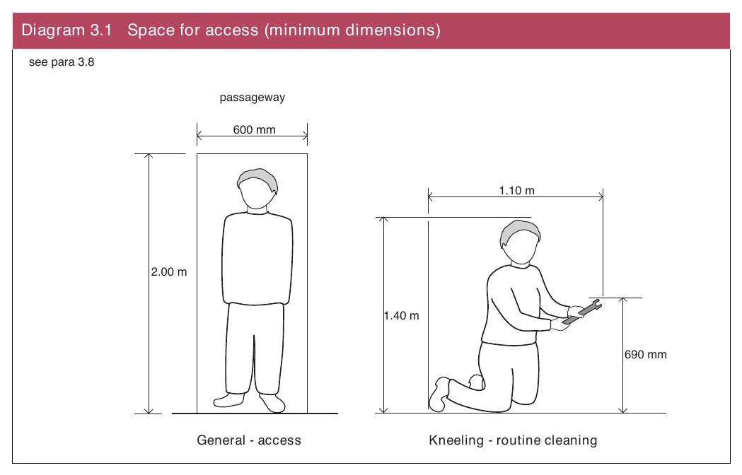
OFFICES
GENERAL
3.9This Section gives four methods of ventilating offices, by – Method 1 – providing a ventilation system that meets the air flow rates set out in paragraphs 3.10 to 3.14; or Method 2 – following the system guidance set out in paragraphs 3.15 to 3.26; or Method 3 – using the alternative approaches set out in paragraph 3.27; or Method 4 – using other ventilation systems set out in paragraph 3.28.
METHOD 1 – VENTILATION RATES
3.10The performance will be achieved by ventilation which provides the air flow rates set out in paragraphs 3.11 to 3.14. The air flow rates specified are for the installed performance.
3.11Extract to outside is required in all office sanitary accommodation, washrooms and in food and beverage preparation areas. In addition, printers and photocopiers in substantial use (greater than 30 minutes per hour) should be located in a separate room (to avoid any pollutants entering the occupied space) and extract provision installed. The extract flow rates should be not less than those specified in Table 3.1.
Page 46
#Source page 46
Table 3.1 Extract ventilation rates
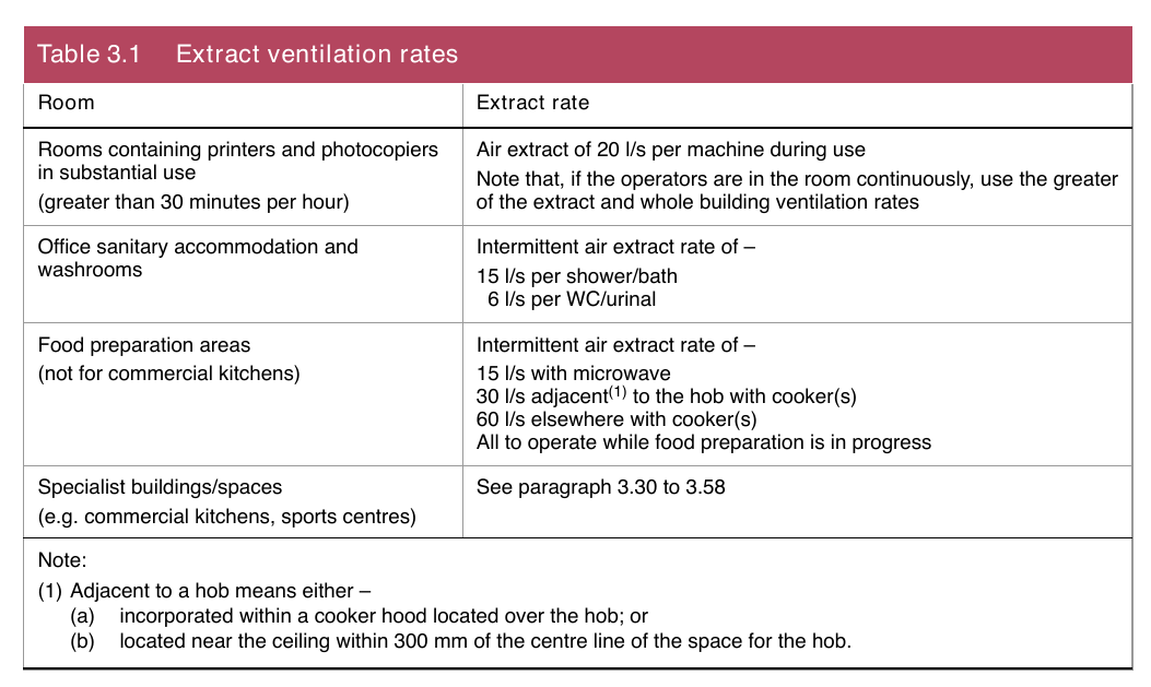
| Room | Extract rate |
| Rooms containing printers and photocopiers in substantial use (greater than 30 minutes per hour) | Air extract of 20 l/s per machine during use Note that, if the operators are in the room continuously, use the greater of the extract and whole building ventilation rates |
| Office sanitary accommodation and washrooms | Intermittent air extract rate of – 15 l/s per shower/bath 6 l/s per WC/urinal |
| Food preparation areas (not for commercial kitchens) | Intermittent air extract rate of – 15 l/s with microwave 30 l/s adjacent(1) to the hob with cooker(s) 60 l/s elsewhere with cooker(s) All to operate while food preparation is in progress |
| Specialist buildings/spaces (e.g. commercial kitchens, sports centres) | See paragraph 3.30 to 3.58 |
| Note: (1) Adjacent to a hob means either – (a) incorporated within a cooker hood located over the hob; or (b) located near the ceiling within 300 mm of the centre line of the space for the hob. |
3.12The whole building ventilation rate for the supply of air to the offices should be not less than that specified in Table 3.2.
3.13Rapid ventilation provision is required in each office (see paragraph 2.28). The total ventilation should be sufficient to reduce pollutants to an acceptable level before the space is occupied. The purged air should be taken directly to outside and should not be recirculated to any other part of the building.
3.14The outdoor air supply rates in Table 3.2 for offices are based on controlling body odours with low levels of other pollutants. Where there are significant levels of other pollutants, adequate outdoor air supply can be achieved by following the calculation method provided in CIBSE Guide A.
| Table 3.2 Whole building ventilation rate for air supply to offices | |
|---|---|
| Air supply rate | |
| Total outdoor air supply rate for offices (no smoking and no significant pollutant sources) | 10 l/s per person |
Page 47
#Source page 47
METHOD 2 – SYSTEM GUIDANCE
3.15The air flow rates specified in Tables 3.1 and 3.2 can be provided with a mainly natural ventilation system by following the guidance in paragraphs
3.16to 3.25. A wide range of natural ventilation systems for providing whole building ventilation is given in CIBSE Application Manual AM10.
Ventilation for offices with natural air supply
Ventilation provisions
Extract
3.16Extract rates should be in accordance with paragraph 3.11.
PSV can be used as an alternative to a mechanical extract fan for office sanitary accommodation, washroom and food preparation areas.
When an openflued appliance is provided in a building with mechanical extract, the spillage of flue gases could occur. The openflued appliance needs to operate safely whether or not the fan is running. Guidance in relation to the interaction of mechanical extract ventilation and open flued appliances is given in Technical Booklet L.
Whole building ventilation
3.17See CIBSE Application Manual AM10.
Rapid ventilation
3.18See CIBSE Application Manual AM10.
Location of ventilators in rooms
Extract
3.19Extract ventilators should be located as high as practicable and preferably within 400 mm of the ceiling. This will tend to remove pollutants from the breathing zone of the occupants as well as increase the effectiveness of extracting buoyant pollutants and water vapour.
For PSV, extract terminals should be located in the ceiling of the room.
Whole building ventilation
3.20See CIBSE Application Manual AM10.
Rapid ventilation
3.21See CIBSE Application Manual AM10.
Page 48
#Source page 48
Controls for ventilators in rooms
Extract
3.22Extract fans can be controlled either manually or automatically. For a room with no openable window (i.e. an internal room), the extract should have an overrun of at least 15 minutes, except where it is controlled by a humidistat.
For PSV, the ventilation can be controlled either manually and/or automatically by a sensor or controller.
Whole building ventilation
3.23See CIBSE Application Manual AM10.
Rapid ventilation
3.24See CIBSE Application Manual AM10.
Accessible controls
3.25Readily accessible override controls should be provided for the occupants.
Mechanical ventilation of rooms
3.26The requirement will be satisfied by following –
(a)the air flow rates set out in paragraphs 3.10 to 3.14; and
(b)the location guidance in paragraphs 3.19 to 3.21 for extract ventilation; and
(c)the control guidance in paragraph 3.22 to 3.25 for extract ventilation.
METHOD 3 – ALTERNATIVE APPROACHES
3.27As an alternative to paragraphs 3.10 to 3.14 the requirement will be satisfied by following the relevant recommendations of –
(a)CIBSE Application Manual AM13; and
(b)CIBSE Guide A and CIBSE Guide B2.
METHOD 4 – OTHER VENTILATION SYSTEMS
3.28Other ventilation systems can be used provided it can be demonstrated to the district council that they satisfy Part K (e.g. by showing that they meet the moisture and performancebased ventilation requirements in Appendix A).
OTHER BUILDING TYPES
#Source page 49
3.29Paragraphs 3.30 to 3.58 provide a list of codes and standards for ventilation design for other building types, which if followed, should demonstrate compliance with Part K. In addition to the guidance documents listed, it should be noted that the Workplace (Health, Safety, and Welfare) Regulations (NI) 1993 apply to most places where people work. A short guide, INDG244, is available from the HSE. (See also Appendix E).
Animal husbandry
3.30Welfare of Farmed Animals Regulations (Northern Ireland) 2012 No.156.
BS 5502: 2003 Buildings and Structures for Agriculture.
See also CIBSE Guide B: 2005, Section 2.3.24.1 and CIBSE AM10: 2005 if naturally ventilated.
Assembly halls
3.31CIBSE Guide B: 2005, Section 2.3.3 and CIBSE AM10: 2005 if naturally ventilated or CIBSE AM13: 2000 if mixed mode (see para 1.10).
Atria
3.32CIBSE Guide B: 2005, Section 2.3.4 and CIBSE AM10: 2005 if naturally ventilated or CIBSE AM13: 2000 if mixed mode (see para 1.10).
Broadcasting studios
3.33CIBSE Guide B: 2005, Section 2.3.5.
Building services plant rooms
3.34Provision for emergency ventilation to control dispersal of contaminating gas releases (e.g.refrigerant leak) is given in paragraphs 2325 of HSE Guidance Note 202 General Ventilation in the Workplace – Guidance for Employers.
Other guidance is in BS 4434: 2005 Specification for safety aspects in the design, construction and installation of refrigeration appliances and systems.
Call centres
3.35CIBSE Guide B: 2005, Section 2.3.24.2 and CIBSE AM10: 2005 if naturally ventilated or CIBSE AM13: 2000 if mixed mode (see para 1.10).
Catering (including commercial kitchens)
3.36HSE Catering Information Sheet No. 10, 2000: Ventilation of kitchens in catering establishments. HSE Information Sheet No. 11, 2000: The main health and safety law applicable to catering.
See also CIBSE Guide B: 2005, Section 2.3.6 and HVCA DW /172 Specification for kitchen ventilation systems.
Page 50
#Source page 50
Cleanrooms
3.37CIBSE Guide B: 2005, Section 2.3.7.
Common spaces
3.38The following provisions apply to common spaces where large numbers of people are expected to gather, such as shopping malls and foyers. They do not apply to common spaces used solely or principally for circulation.
Either –
(a)natural ventilation by appropriately located opening(s) with a total opening area of at least 1/50th of floor area of the common space; or
(b)mechanical ventilation installed to provide a supply of fresh air of 1 l/s per m2 of floor area.
Communal residential buildings
3.39EST, Energy Efficiency Best Practice in Housing, Good Practice Guide GPG 192: Designing energy efficient multiresidential buildings.
See also CIBSE Guide B: 2005, Section 2.3.8 and CIBSE AM10: 2005 if naturally ventilated or CIBSE AM13: 2000 if mixed mode (see para 1.10).
Computer rooms
3.40CIBSE Guide B: 2005, Section 2.3.9 and CIBSE AM10: 2005 if naturally ventilated or CIBSE AM13: 2000 if mixed mode (see para 1.10).
Darkrooms (photographic)
3.41CIBSE Guide B: 2005, Section 2.3.24.4.
Dealing rooms
3.42CIBSE Guide B: 2005, Section 2.3.24.5 and CIBSE AM10: 2005 if naturally ventilated or CIBSE AM13: 2000 if mixed mode (see para 1.10).
Factories and warehouses
3.43Factories Act (NI) 1965 Chapter 20.
Health and Safety (NI) Order 1978.
See also CIBSE Guide B: 2005, Section 2.3.11 and CIBSE AM10: 2005 if naturally ventilated or CIBSE AM13: 2000 if mixed mode (see para 1.10). Requirements are often exceeded by other criteria such as the ventilation requirements of the particular manufacturing process.
Highrise (nondomestic buildings)
3.44CIBSE Guide B: 2005, Section 2.3.12 and CIBSE AM10: 2005 if naturally ventilated or CIBSE AM13: 2000 if mixed mode (see para 1.10).
Page 51
#Source page 51
Horticulture
3.45CIBSE Guide B: 2005, Section 2.3.24.6 and CIBSE AM10: 2005 if naturally ventilated or CIBSE AM13: 2000 if mixed mode (see para 1.10).
Hospitals and healthcare buildings
3.46NHS Activity database. Health Technical Memorandum (HTM) 0301 Parts A and B. Health Building Notes (HBN) – various. CIBSE Guide B: 2005, Section 2.3.13 and CIBSE AM10: 2005 if naturally ventilated or CIBSE AM13: 2000 if mixed mode (see para 1.10).
Hotels
3.47CIBSE Guide B: 2005, Section 2.3.14 and CIBSE AM10: 2005 if naturally ventilated or CIBSE AM13: 2000 if mixed mode (see para 1.10).
Industrial ventilation
3.48Industrial ventilation, 24th Edition, Manual of recommended practice, American Conference of Government Industrial Hygienists. HS(G) 37 An introduction to local exhaust ventilation.
HS(G) 54 Maintenance, examination and testing of local exhaust ventilation. HS(G) 193 COSHH essentials.
Laboratories
3.49CIBSE Guide B: 2005, Section 2.3.16.
Museums, libraries and art galleries
3.50BS 5454: 2000.
CIBSE Guide B: 2005, Section 2.3.17 and CIBSE AM10: 2005 if naturally ventilated or CIBSE AM13: 2000 if mixed mode (see para 1.10).
Plant rooms
3.51CIBSE Guide B: 2005, Section 2.3.18.
Prison cells
3.52Refer to National Offender Management Service (NOMS). Home Office, NOMS Property, Technical Services, Room 401, Abell House, John Islip St., London SW1P 4LH.
Page 52
#Source page 52
Schools and educational buildings
3.53Ventilation provisions in schools can be made in accordance with the guidance in Building Bulletin (BB) 101, Ventilation of School Buildings and in the Education (School Premises) Regulations. BB 101 can also be used as a guide to the ventilation required in other educational buildings such as further education establishments where the accommodation is similar to that found in schools (e.g. sixth form accommodation). However, the standards may not be appropriate for particular areas where more hazardous activities take place than are normally found in schools (e.g. some practical and vocational activities requiring containment or fume extraction, see Building Bulletin 88 Fume cupboards in schools).The BB can also be used for children’s centres and other early years settings, including day nurseries, playgroups, etc.
Shops and retail premises
3.54CIBSE Guide B: 2005, Section 2.3.20 and CIBSE AM10: 2005 if naturally ventilated or CIBSE AM13: 2000 if mixed mode (see para 1.10).
Sports centres (including swimming pools)
3.55CIBSE Guide B: 2005, Section 2.3.21.
Standards rooms
3.56CIBSE Guide B: 2005, Section 2.3.24.7.
Sanitary accommodation
3.57Same as for offices in Table 3.1.
Transportation buildings and facilities
3.58CIBSE Guide B: 2005, Section 2.3.23 and CIBSE AM10: 2005 if naturally ventilated or CIBSE AM13: 2000 if mixed mode (see para 1.10).
Page 53
#Source page 53
Section 4 Ventilation of replacement windows
4.1The regulations require that, when windows in an existing building are replaced, the replacement work should comply with all the applicable Parts in the regulations. In addition, the completed building work should not create a new or greater contravention with other applicable requirements than before commencement of the work.
4.2Replacement windows should have rapid ventilation openings sized according to Appendix B, see paragraph 2.28.
4.3Where the original windows were fitted with trickle ventilators the replacement windows should also include trickle ventilators and they should be sized as set out in paragraph 4.6.
4.4Where the original windows were not fitted with trickle ventilators and the room is not ventilated adequately by other installed provisions, background ventilation should be provided in the form of trickle ventilators (or an equivalent means of ventilation (see Diagram 1.1)) to assist with the control of condensation within dwellings and improve indoor air quality. Ventilation devices should be fitted with accessible controls.
4.5When windows are replaced as part of the work connected with a material change of use or a new service is fitted (e.g. MVHR), Sections 2 and 3 of this Technical Booklet apply.
4.6In all cases where trickle ventilators (or an equivalent means of ventilation) are to be fitted, the new ventilation opening should not be smaller than was originally provided, and it should be controllable. Where there was no ventilation opening, or where the size of the original ventilation opening is not known, the following minimum sizes should be adopted –
(a)dwellings –
(i)habitable rooms – 5000 mm2 equivalent area;
(ii)kitchen, utility room and bathroom (with or without WC) – 2500 mm2 equivalent area; and
(b)buildings other than dwellings –
(i)occupiable rooms: for floor areas up to 10 m2 – 2500 mm2 equivalent area; greater than 10 m2 at the rate of 250 mm2 equivalent area per m2 of floor area;
(ii)kitchens (domestic type) – 2500 mm2 equivalent area;
(iii) bathrooms and shower rooms – 2500 mm2 equivalent area per bath or shower; and
(iv) sanitary accommodation (and/or washing facilities) – 2500 mm2 equivalent area per WC.
Page 54
#Source page 54
Section 5 Ventilation of car parks
5.1Car parking areas within a building should be ventilated using the following design approaches –
(a)Natural ventilation The provision of well distributed permanent natural ventilation
•(e.g. openings at each car parking level with an aggregate equivalent area equal to at least 1/20th of the floor area at that level, of which at least 25% should be on each of two opposing walls); or
(b)Mixed mode and mechanical ventilation Either –
(i)the provision of both permanent natural ventilation openings of equivalent area not less than 1/40th of the floor area and a mechanical ventilation system capable of not less than 3 air changes per hour; or
(ii)for basement car parks, the provision of a mechanical ventilation system capable of not less than 6 air changes per hour; and
for exits and ramps, where cars queue inside the building with engines running, provisions should be made to ensure a local ventilation rate of not less than 10 air changes per hour. Reference should also be made to paragraphs 2.36 to 2.39 regarding noise.
5.2It should be noted that Technical Booklet E also includes provisions for the ventilation of car parks for the purpose of satisfying Part E.
Alternative design approach for ventilation of car parks
5.3An alternative design approach for the ventilation of a car park to those approaches given in paragraph 5.1 is where the mean predicted pollutant levels are calculated and the ventilation rate is designed and equipment is installed to limit the carbon monoxide to –
(a)an average concentration of not more than 30 parts per million over an 8 hour period; and
(b)peak concentrations, such as at ramps and exits, of not more than 90 parts per million for periods not exceeding 15 minutes.
5.4Further guidance can be found in Code of practice for ground floor, multi storey and underground car parks published by the Association for Petroleum and Explosives Administration; CIBSE Guide B: 2005, Section 2.3.23.3; and Health and Safety Publication EH40: Occupational exposure limits for limiting concentration of exhaust pollutants.
Page 55
#Source page 55
Appendix A Performancebased ventilation
Introduction
A1This Appendix sets out the levels of moisture and other pollutants that the provisions in this Technical Booklet are designed to control.
A2The guidance within this Technical Booklet may not be adequate to address pollutants from flueless combustion space heaters or from occasional, occupantcontrolled events such as painting, smoking, cleaning or other highpolluting events. It does not address the airborne spread of infection or contamination from outdoor sources. While many of these considerations could be important factors in achieving acceptable indoor air quality, solutions are not ready for inclusion in this guidance, and indeed indoor air quality may be better controlled at source (e.g. avoidance, isolation or use of lower emitting products).
Performance criteria for dwellings
A3The performance criterion for moisture is that there should be no visible mould on external walls in a properly heated dwelling with typical moisture generation.
A4The principal performance criteria used for other indoor air pollutants are as follows –
(a)exposure to the following levels of nitrogen dioxide (NO2) should not be exceeded –
(i)288 μg/m3 (150 ppb) – 1 hour average (DOH, 2004); or
(ii)40 μg/m3 (20 ppb) – longterm average (DOH, 2004).
(b)exposure to the following levels of carbon monoxide should not be exceeded –
(i)100 mg/m3 (90 ppm) – 15 minute averaging time (DOH, 2004);
(ii)60 mg/m3 (50 ppm) – 30 minute averaging time (DOH, 2004);
(iii)30 mg/m3 (25 ppm) – 1 hour averaging time (DOH, 2004); or
(iv)10 mg/m3 (10 ppm) – 8 hours averaging time (DOH, 2004).
(c)exposure to Total Volatile Organic Compound (TVOC) levels should not exceed 300 μg/m3 averaged over 8 hours (ECA, 1992); and
(d)control of human odour (reduction in perception due to being exposed to the environment for a period of time) will be achieved by an air supply rate of 3.5 l/s per person (ASHRAE, 2003).
A5Mould growth can occur whether the dwelling is occupied or unoccupied, so the performance criteria for moisture (as set out in Table A2) should be met at all times, regardless of occupancy. The other pollutants listed above are only harmful to the occupants when the dwelling is occupied.
Page 56
#Source page 56
Assumptions used in applying performance criteria for dwellings in Section 2
General
A6For the default option in which the design air permeability can be any value, dwellings with ventilation System 1 or 2 are assumed to have an infiltration of 0.05 ach (air changes per hour); and dwellings with ventilation Systems 3 or 4 are assumed to have no infiltration.
A7For the alternative option in which the design air permeability is greater than 5 m 3/(h.m2) at 50 Pa, dwellings with ventilation Systems 1, 2 or 4 are assumed to have an infiltration of 0.15 ach, and dwellings with ventilation System 3 are assumed to have negligible infiltration, see paragraph 2.66.
A8The ventilation effectiveness is 1.0.
A9For the purpose of this Technical Booklet, for all dwellings (new and existing where Part K applies), the moisture criterion is likely to be met if the moving average surface water activity of the internal surfaces of external walls is always less than the value noted in Table A1 during the heating season, evaluated over each of the stated averaging periods. Table A1 is the primary basis for demonstrating compliance with the moisture criterion.
Table A1 Surface water activity
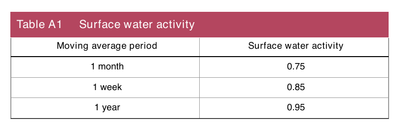
| Moving average period | Surface water activity |
| 1 month | 0.75 |
| 1 week | 0.85 |
| 1 year | 0.95 |
A10As a guide, for new dwellings, for the purpose of this Technical Booklet, the moisture criteria in Table A1 are likely to be met if the moving average relative humidity (RH) in a room is always less than the value given in Table A2 during the heating season, evaluated over each of the stated averaging periods.
Table A2 Indoor air relative humidity
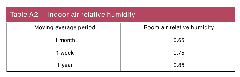
| Moving average period | Room air relative humidity |
| 1 month | 0.65 |
| 1 week | 0.75 |
| 1 year | 0.85 |
Page 57
#Source page 57
Extract ventilation
A11The principal pollutant to be removed by extract ventilation is moisture. The source rates were taken from BS 5250 Table B.1.
A12For intermittent extract –
(a)a ventilation rate of 60 l/s is specified in kitchens for the removal of moisture. This ventilation rate removes moisture generated at a production rate of 2000 g/h. A reduced rate of 30 l/s is used for a cooker hood, owing to the greater ventilation effectiveness;
(b)a ventilation rate of 15 l/s is specified in bathrooms for the removal of moisture. This ventilation rate removes moisture generated at a production rate of 400 g/h;
(c)it is assumed that the ventilation rate required in the utility room is 50% of that in the kitchen; and
(d)a ventilation rate of 6 l/s has been specified in WCs for the removal of odour.
A13For continuous extract the rates in Table 2.1 are used.
Whole dwelling ventilation
A14The principal pollutant to be removed by whole dwelling ventilation is moisture. The source rates were taken from BS 5250 Table B.1.
A15It was assumed that local extract removes 100% of the moisture generated in the bathroom and 50% of the moisture generated in the kitchen.
A16The rates are given in Table 2.2.
A17The calculations were based on winter weather conditions. During warmer spring and autumn periods, the moisture removal capacity of the outdoor air will be less (i.e. the outdoor air on being heated to the internal temperature within the dwelling will have a higher relative humidity in the spring and autumn periods) and additional ventilation may be required. The provisions for rapid ventilation (e.g. windows) may be used for this purpose.
A18There are other pollutants that must also be adequately controlled. These are particularly important in homes of low occupant density where moisture production is low for the size of the property. Levels of volatile organic compounds were monitored in a BRE study of UK homes (Dimitroulopoulou et al 2005).
From this study, the total source production rate of volatile organic compounds was determined to be 300 μg/h per m2 of floor area. To meet the performance criterion of 300 μg/m3 requires a minimum whole dwelling ventilation rate of 0.3 l/s per m2 of internal floor area.
Page 58
#Source page 58
Rapid ventilation
A19A value of 4 ach has been selected as –
(a)it provides a rapid ventilation rate an order of magnitude above whole building ventilation; and
(b)the calculation assumes singlesided ventilation for a dwelling in an urban environment and an internal/external temperature difference of 3 °C.
Basis of whole dwelling ventilation rates
A20In determining the ventilation rates, the air supply rates in Table 2.2 have been used.
A21For dwellings having an air permeability of greater than 5 m3/(h.m2) at 50 Pa, the air supply rate has been reduced by 0.15 ach to allow for infiltration.
A22To determine the equivalent areas, the standard air flow equation has been used as below – A = 1000.(Q/C d).(ρ/ 2.Δ P)0.5 Where – A = the background ventilator equivalent area (mm2) Q = the air supply rate (l/s) C d = the discharge coefficient, taken as 0.61 ρ = the air density (kg/m3), taken as 1.2 Δ P = the pressure across the vent, which has been taken as 0.6 Pa for singlestorey dwellings and 1.0 Pa for multistorey dwellings.
The total actual equivalent area required (A T) is double that derived from the equation above, which only provides the equivalent area for air supplied to the dwelling. A similar equivalent area is required for air to exit the dwelling. The total equivalent area determined in this way is given in the guidance for Systems 1 and 2. Note that in determining these pressure differences, a meteorological wind speed of 4 m/s at 10 m height was taken (based on BS 5925) and an internal/external temperature difference of 15 °C.
Performance criteria for buildings other than dwellings
A23The main guidance within this document has focused on offices. For this, the main criteria have been –
(a)a supply rate, in the absence of tobacco smoking or other excessive pollutants, of 10 l/s per person, based upon surveys which indicate that below this level the incidence of health effects becomes increasingly significant. This will also satisfy the requirement of 8 l/s per person needed to control human odour;
(b)there should be no visible mould on external walls in a properly heated building with typical moisture generation;
Page 59
#Source page 59
(c)exposure to the following levels of nitrogen dioxide (NO2) should not be exceeded –
(i)288 μg/m3 (150 ppb) – 1 hour average (Department of the Environment, 1996); or
(ii)40 μg/m3 (21 ppb) – longterm average (WHO, 2003);
(d)exposure to the following levels of carbon monoxide should not be exceeded –
(i)100 mg/m3 (90 ppm) – 15 minute averaging time (WHO, 2000);
(ii)60 mg/m3 (50 ppm) – 30 minute averaging time (WHO, 2000);
(iii)30 mg/m3 (25 ppm) – 1 hour averaging time (WHO, 2000); or
(iv)10 mg/m3 (10 ppm) – 8 hours averaging time (Department of the Environment, 1994a).
(e)exposure to the following levels of carbon monoxide for occupational exposure should not be exceeded –
35mg/m3 (30 ppm) – 8 hours averaging time (HSE, 2003).
(f)exposure to Total Volatile Organic Compound (TVOC) levels should not exceed 300 μg/m3 averaged over 8 hours (ECA, 1992); and
(g)ozone levels should not exceed 100 μg/m3 (Department of the Environment, 1994b).
The guidance within this Technical Booklet may not be adequate to address pollutants from occasional, occupantcontrolled activities such as painting, smoking, cleaning or other highlypolluting activities. While these could be important factors in achieving acceptable indoor air quality, solutions are not ready for inclusion in this guidance, and indeed they may be better controlled at source (e.g. by avoidance, isolation or the use of lower emitting products).
A24Mould growth can occur whether the building is occupied or unoccupied, so the performance criteria for moisture (as set out in Table A1) should be met at all times, regardless of occupancy. The other pollutants listed above are only harmful to the occupants when the building is occupied.
A25Where the Health and Safety Executive Northern Ireland gives ventilation performance criteria guidance for specific situations, it should be followed in preference to the guidance given here.
Assumptions used in applying performance criteria for offices in Section 3
General
A26The office has an air permeability of 3 m3/(h.m2) at 50 Pa.
A27At this level of air permeability, in large buildings (low ratio of surface area to volume contained), infiltration can be assumed to be negligible compared with the purpose provided ventilation.
A28The ventilation effectiveness is 0.9 (for Table 3.1).
Page 60
#Source page 60
A29For the purposes of this Technical Booklet, the moisture criterion should be met if the surface water activity in a room does not exceed the values given in Table A1 during the heating season.
Extract ventilation
A30Office equipment can emit pollutants including ozone and organic compounds. For example, a study by Black and Wortham (1999) suggests the following emission rates for laser printers and dry paper copiers assuming 30 minutes continual use in an hour –
(a)25 mg/h for TVOCs; and
(b)3 mg/h for ozone.
To meet the performance criteria for these pollutants requires an extract rate of 20 l/s per machine during use.
A31For sanitary accommodation, the extract rates used for dwellings have been applied.
A32For food and beverage preparation areas, the extract rates used for dwellings have been applied.
Whole building ventilation
A33A number of studies have investigated ventilation and health in offices (principally sick building syndrome). Although there is no clear threshold ventilation rate below which health suddenly worsens, a number of sources have identified 10 l/s per person as a significant level. This can probably be traced back to an analysis of experimental studies of office buildings by Mendell (1993). Hence the recommendation within this Technical Booklet is for 10 l/s per person for buildings with no smoking and no significant pollutant sources.
A34Increasing the ventilation rate above 10 l/s per person may improve health (results unclear), but there are diminishing returns (i.e. the improvement in health per l/s per person increase in ventilation rate becomes smaller as the ventilation rate increases). It suggests that there is little advantage in increasing the whole building ventilation rate above 10 l/s per person. Increased ventilation has a cost in economic and environmental terms. Having set a ventilation rate of 10 l/s per person, if further improvements in indoor air quality are necessary, alternative approaches should be considered first (e.g. the use of lowemission materials).
Rapid ventilation
A35There are normally more options for the removal of high concentrations of pollutants from office spaces than for dwellings (e.g. leaving rooms unoccupied until acceptable pollutant levels are achieved). Hence, general guidance has been provided rather than specifying any ventilation rate(s).
Page 61
#Source page 61
Table A3 Definitions of abbreviations used in Appendix A
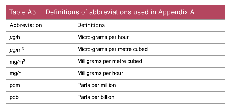
Further Guidance
AltamiranoMedina H., Mumovic D., Davies M., Ridley I., Oreszczyn T., (2009), Guidelines to avoid mould growth in buildings, Advanced Buildings Energy Research, 3, pp 221236.
ASHRAE. Handbook 2007: HVAC applications.
Black M S and Wortham A W (1999). Emissions from office equipment. Proceedings of the 8th International Conference on Indoor Air Quality and Climate, Indoor Air 99, Edinburgh 813 August 1999, Vol. 2, pp 455459.
Department of the Environment (1994a). Expert panel on air quality standards: Carbon monoxide. London, HMSO. www.defra.gov.uk/environment/airquality/panels/aqs/publications/index.htm.
Department of the Environment (1994b). Expert panel on air quality standards: Ozone. London, HMSO. www.defra.gov.uk/environment/airquality/panels/aqs/publications/index.htm.
Department of the Environment (1996). Expert panel on air quality standards: Nitrogen dioxide. London, The Stationery Office. www.defra.gov.uk/environment/airquality/panels/aqs/publications/index.htm.
Department of Health (2004). Committee on the Medical Effects of Air Pollutants. Guidance on the effects on health of indoor air pollutants. www.advisorybodies.doh.gov.uk/comeap/PDFS/guidanceindoorairqualitydec04.pdf.
Dimitroulopoulou C, Crump D, Coward S K D, Brown V, Squire R, Mann H, White M, Pierce B and Ross D (2005). Ventilation, air tightness and indoor air quality in new homes. Report BR 477. BRE bookshop.
ECA (1992). European Concerted Action on indoor air and its impact on man: Guidelines for ventilation requirements in buildings. Working Group Report No.11. EUR 14449 EN. Commission of the European Communities, Luxembourg.
HSE (2003). Occupational exposure limits 2002, plus supplement 2003. HSE Books.
Mendell M J (1993). Nonspecific symptoms in office workers: a review and summary of the epidemiologic literature. Indoor air 3, pp 227236.
Page 62
#Source page 62
Ross D I and Wilde D (1999). Continuous monitoring of nitrogen dioxide and carbon monoxide levels in UK homes. Proceedings of the 8th International Conference on Indoor Air Quality and Climate, Indoor Air 99, Edinburgh 813 August 1999, Vol. 3, pp 147152.
WHO (2005). Guidelines for air quality. World Health Organization, Geneva.
WHO (2003). WHO working group meeting: Review of health aspects of air pollution with particulate matter, ozone and nitrogen dioxide, Bonn, Germany, 1315 January 2003.
Page 63
#Source page 63
Appendix B Rapid ventilation
Introduction
B1Adequate rapid ventilation may be achieved by the use of openable windows and/or external doors. This Appendix provides details of necessary window and door sizes. The diagrams highlight the important window dimensions (see Diagram B.1).
Where an externally accessible rapid ventilation opening provides the sole means of night time cooling the issue of security should be considered.
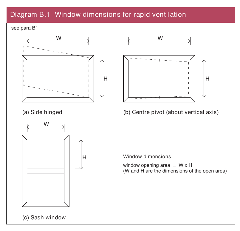
Windows
B2For a hinged or pivot window that opens 30º or more or for parallel sliding windows (e.g. vertical sliding sash windows), the “height x width” of the opening should be at least 1/20th of the floor area of the room.
B3For a hinged or pivot window that opens between 15º and 30º, the “height x width” of the opening part should be at least 1/10th of the floor area of the room.
B4Where a window opens less than 15º it is not suitable for providing rapid ventilation and an alternative means of rapid ventilation should be provided. See paragraph 2.28.
Page 64
#Source page 64
B5Where a room contains more than one openable window, the areas of all the opening parts may be added together to achieve the required proportion of the floor area. The required proportion of the floor area is determined by the opening angle of the largest window in the room.
B6It should be noted that Technical Booklet E includes provisions for the size of emergency egress windows. The larger of the provisions in Technical Booklet E or K should apply in all cases.
External doors (including patio doors)
B7For an external door, the “height x width” of the opening part should be at least 1/20th of the floor area of the room.
B8Where a room contains more than one external door the areas of all the opening parts may be added to achieve at least 1/20th of the floor area of the room.
B9Where a room contains a combination of at least one external door and at least one openable window, the areas of all the opening parts may be added together to achieve at least 1/20th of the floor area of the room.
Further information
B10The aim of this guidance is to achieve a rapid ventilation rate of 4 air changes per hour. It provides a rapid ventilation rate of an order of magnitude above the whole building ventilation rate.
B11The guidance contained within this Appendix is a simplification of guidance in BS 5925. This Appendix has assumed singlesided ventilation for dwellings in an urban environment (local wind speed of 2.1 m/s) and a summertime internal/external temperature difference of 3 °C. It has considered and simplified variations in air flow rates caused by factors including window type and window height.
B12This design guidance should deliver 4 air changes per hour in most cases. Depending on the dwelling design or the external climate, it may be possible to achieve this ventilation rate through a smaller window opening area. BS 5925 provides a good starting point for determining the window openings required. It may be beneficial to also seek expert advice.
Page 65
#Source page 65
Appendix C Example calculations for ventilation sizing for dwellings
Introduction
C1This Appendix provides example calculations for each ventilation system set out in paragraph 2.11. A ground floor flat and a semidetached house have been considered for each system type. There are eight examples as follows –
Ground floor flat
Example C1 – Background ventilators and intermittent extract fans Example C2 – Passive stack ventilation Example C3 – Continuous mechanical extract Example C4 – Continuous mechanical supply and extract
Semidetached house
Example C5 – Background ventilators and intermittent extract fans Example C6 – Passive stack ventilation Example C7 – Continuous mechanical extract Example C8 – Continuous mechanical supply and extract
It has been assumed that the intended measured air permeability is greater than 5 m3/(h.m2) in examples C1, C2, C5 and C6, and the design air permeability is equal to or less than 3 m3/(h.m2) in examples C3, C4, C7 and C8.
Details of ground floor flat
Description
The floor plan is given in Diagram C1 and contains a –
(a)kitchen;
(b)combined living/dining room;
(c)one double bedroom;
(d)internal bathroom containing WC; and
(e)all rooms have an external wall except for the bathroom.
Page 66
#Source page 66
Assumptions
The following assumptions have been made –
(a)the cooker hood is adjacent to the cooker hob;
(b)gross internal volume of the heated space of 83 m3;
(c)total floor area of 36 m2;
(d)two person occupancy; and
(e)sidehinged windows 1.0 m high and openable to 60°.
Diagram C1 Ground floor flat plan
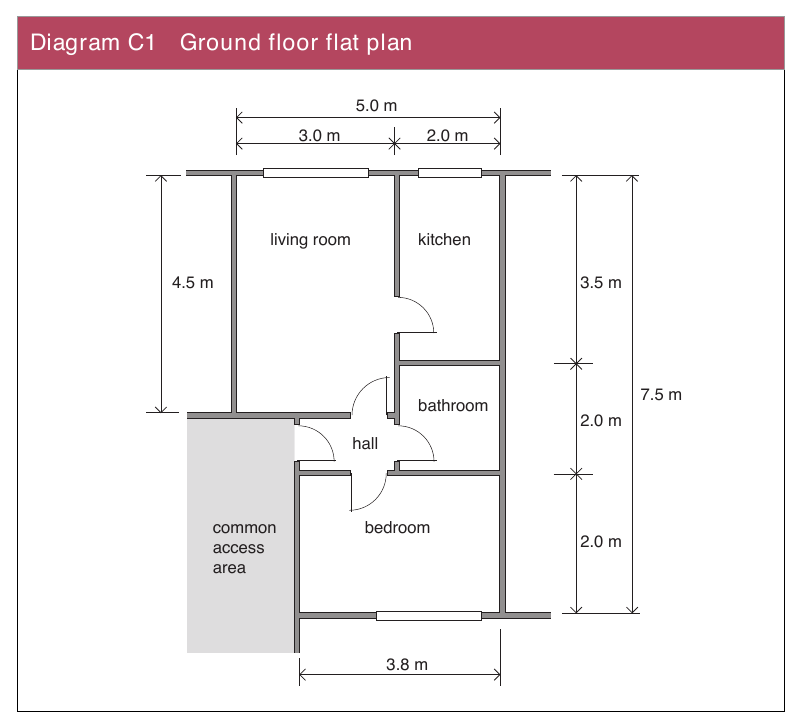
Example C1: Background ventilators and intermittent extract fans (based on paragraphs 2.12 to 2.40)
| Intermittent extract | |
|---|---|
| Room | Intermittent extract rate |
| Kitchen | 30 l/s (adjacent to hob) |
| Bathroom | 15 l/s |
Background ventilators
For a single storey ground floor dwelling of 36 m2 floor area, paragraph 2.19 shows that the equivalent background ventilator area is 35000 mm2 (this includes the additional 10000 mm2 as we are considering a single storey building).
Page 67
#Source page 67
To maximise the air flow through the dwelling by encouraging cross ventilation, it is best to locate similar equivalent areas of background ventilators on opposite sides of the dwelling.
Rapid ventilation
Calculate the percentage window opening area (percentage of floor area) for each room having an external wall.
Using Appendix B with an opening angle of 60° gives 1/20th of the floor area.
Therefore, for a living room of 13.5 m2 floor area there should be a window opening area of at least 0.68 m2. This calculation should be repeated for each habitable room.
Example C2: Passive stack ventilation (based on paragraphs 2.41 to 2.64)
| Choose appropriate passive stack ventilation provision | ||
|---|---|---|
| Room | Internal duct diameter (mm) | Internal cross sectional area (mm²) |
| Kitchen | 125 | 12000 |
| Bathroom | 100 | 12000 |
Background ventilators
Calculate the total equivalent area of ventilators required for a dwelling as follows –
Step 1 – For a single storey ground floor dwelling of 36 m2 floor area, paragraph 2.47 shows that the equivalent background ventilator area is 35000 mm2 (this includes the additional 10000 mm2 as we are considering a single storey building).
Step 2 – For a PSV in both the kitchen and bathroom, an allowance of 6000 mm2 can be made. Step 3 – 350002 mm – 60002 mm = 29000 mm2.
In addition, the equivalent area must be at least the total crosssectional area of the ducts (24000 mm2), which it is. It should be distributed with similar areas on opposite sides of the dwelling (but not in the kitchen and bathroom).
Page 68
#Source page 68
Rapid ventilation
Calculate the percentage window opening area (percentage of floor area) for each room having an external wall.
Using Appendix B with an opening angle of 60° gives 1/20th of the floor area.
Therefore, for a living room of 13.5 m2 floor area there should be a window opening area of at least 0.68 m2. This calculation should be repeated for each habitable room.
Example C3: Continuous mechanical extract (based on paragraphs
2.65to 2.84)
Continuous extract
Step 1 –
Whole dwelling ventilation rate is 13 l/s from Table 2.2.
Step 2 –
Whole dwelling extract ventilation rate is 21 l/s from Table 2.1
(assuming extract in kitchen and bathroom).
Step 3 –
Maximum whole dwelling extract rate (i.e. the boost rate) should be at least 21 l/s (with a minimum of 13 l/s in the kitchen and 8 l/s in the bathroom).
The minimum whole dwelling extract rate should be at least 13 l/s (spread between the kitchen and bathroom).
Background ventilators
As the design air permeability is equal to or less than 3 m3/(h.m2) background ventilators of at least 2500 mm2 equivalent area should be located in the living room and bedroom.
Rapid ventilation
Calculate the percentage window opening area (percentage of floor area) for each room having an external wall.
Using Appendix B with an opening angle of 60° gives 1/20th of the floor area.
Therefore, for a living room of 13.5 m2 floor area there should be a window opening area of at least 0.68 m2. This calculation should be repeated for each habitable room.
Page 69
#Source page 69
Example C4: Continuous mechanical supply and extract with heat recovery (based on paragraphs 2.85 to 2.104)
Continuous supply and extract
Step 1 – Whole dwelling supply ventilation rate is 13 l/s from Table 2.2. Step 2 – Whole dwelling extract ventilation rate is 21 l/s from Table 2.1 (assuming extract in kitchen and bathroom). Step 3 – Maximum whole dwelling extract rate (i.e. the boost rate) should be at least 21 l/s (with 13 l/s extract in the kitchen and 8 l/s extract in the bathroom).
The minimum whole dwelling supply rate should be at least 13 l/s.
Rapid ventilation
Calculate the percentage window opening area (percentage of floor area) for each room having an external wall.
Using Appendix B with an opening angle of 60° gives 1/20th of the floor area.
Therefore, for a living room of 13.5 m2 floor area there should be a window opening area of at least 0.68 m2. This calculation should be repeated for each habitable room.
Details of semidetached house
Description
The floor plans are given in Diagrams C2 and C3 and contain –
(a)entrance hall/stairway;
(b)kitchen;
(c)dining room;
(d)living room;
(e)three bedrooms;
(f)bathroom containing WC; and
(g)all rooms have an external wall.
Assumptions
The following assumptions have been made –
(a)cooker hood adjacent to cooker hob;
(b)gross internal volume of the heated space of 210 m3;
(c)total floor area of 84 m2;
(d)four person occupancy; and
(e)sidehinged windows 1.0 m high and openable to a fixed position of 20º.
Page 70
#Source page 70
Diagram C2 Semidetached house ground floor plan
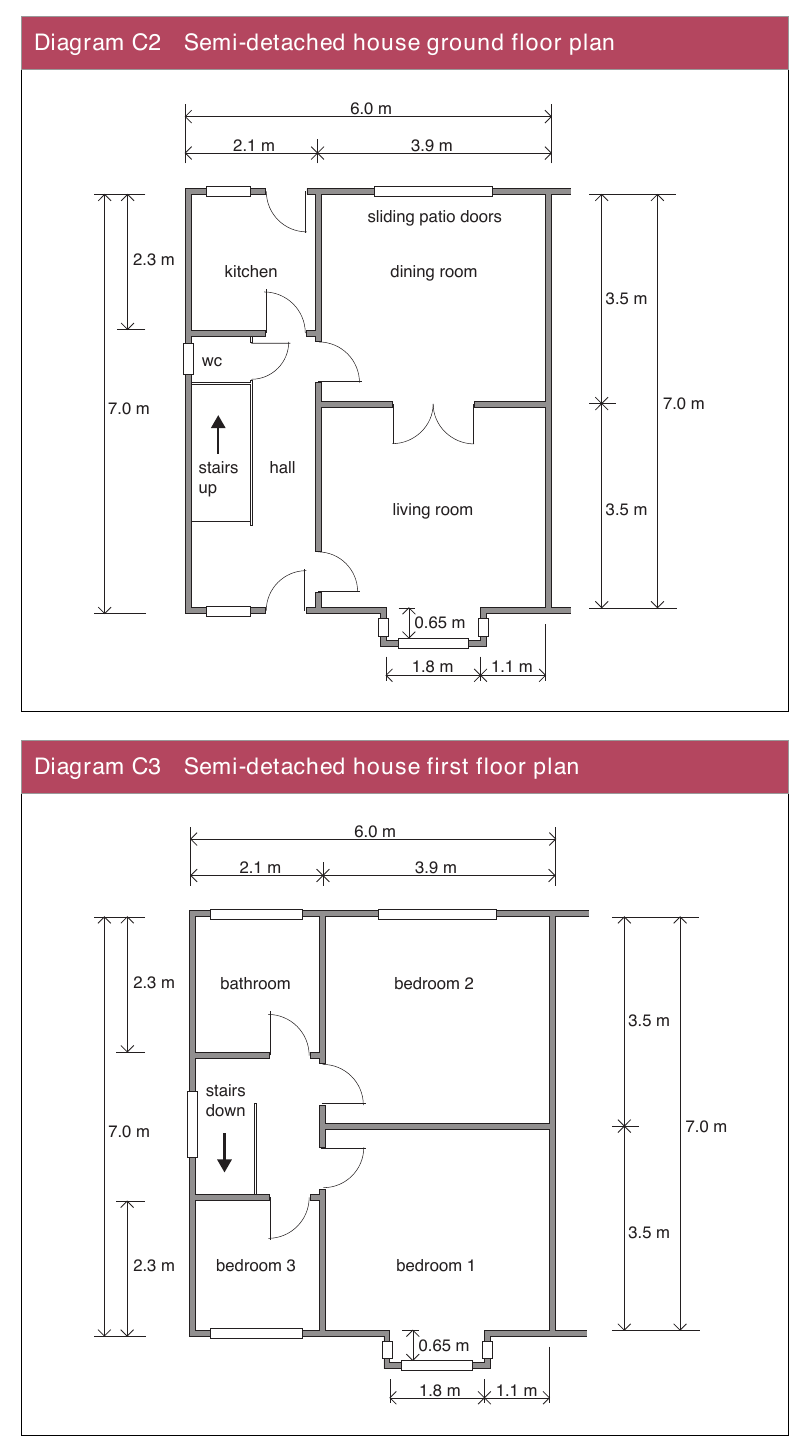
Page 71
#Source page 71
Example C5: Background ventilators and intermittent extract fans (based on paragraphs 2.12 to 2.40)
| Intermittent extract | |
|---|---|
| Room | Intermittent extract rate |
| Kitchen | 30 l/s (adjacent to hob) |
| Bathroom | 15 l/s |
Background ventilators
For a two storey semidetached house of 84 m2 floor area, paragraph 2.19 shows that the equivalent background ventilator area is 40000 mm2.
To maximise the air flow through the dwelling by encouraging cross ventilation, it is best to locate similar equivalent areas of background ventilators on opposite sides of the dwelling.
Rapid ventilation
Calculate the percentage window opening area (percentage of floor area) for each room having an external wall.
Using Appendix B with an opening angle of 20° gives 1/10th of the floor area.
Therefore, for a living room of 14.8 m2 floor area there should be a window opening area of at least 1.48 m2. This calculation should be repeated for each habitable room.
Example C6: Passive stack ventilation (based on paragraphs 2.41 to 2.64)
| Choose appropriate passive stack ventilation provision | ||
|---|---|---|
| Room | Internal duct diameter (mm) | Internal cross sectional area (mm²) |
| Kitchen | 125 | 12000 |
| Bathroom | 125 | 12000 |
Background ventilators
Calculate the total equivalent area of ventilators required for a dwelling as follows –
Step 1 –
For a two storey semidetached house of 84 m2 floor area, paragraph 2.47 shows that the equivalent background ventilator area is 40000 mm2.
Page 72
#Source page 72
Step 2 –
For a PSV in both the kitchen and bathroom, an allowance of
6000 mm2 can be made.
Step 3 –
400002 mm – 60002 mm = 34000 mm2.
In addition, the equivalent area must be at least the total crosssectional area of the ducts (24000 mm2), which it is. It should be distributed with similar areas on opposite sides of the dwelling (but not in the kitchen and bathroom).
Rapid ventilation
Calculate the percentage window opening area (percentage of floor area) for each room having an external wall.
Using Appendix B with an opening angle of 20° gives 1/10th of the floor area.
Therefore, for a living room of 14.8 m2 floor area there should be a window opening area of at least 1.48 m2. This calculation should be repeated for each habitable room.
Example C7: Continuous mechanical extract (based on paragraphs
2.65to 2.84)
Continuous extract
Step 1 –
Whole dwelling ventilation rate from the list in Table 2.2 is 21 l/s.
However – minimum whole dwelling ventilation rate
= 0.3 x floor area = 0.3 x 84 = 25 l/s.
Hence, whole dwelling ventilation rate is 25 l/s.
Step 2 –
Whole dwelling extract rate is 21 l/s from Table 2.1 (assuming extract in kitchen and bathroom).
Step 3 –
In this case the required whole dwelling ventilation rate is greater than the whole dwelling extract ventilation rate, and only a minimum whole dwelling extract ventilation rate of 25 l/s is required (with at least 13 l/s in the kitchen and 8 l/s in the bathroom).
Background ventilators
As the design air permeability is equal to or less than 3 m3/(h.m2) background ventilators of at least 2500 mm2 equivalent area should be located in the living room, dining room and each bedroom.
Page 73
#Source page 73
Rapid ventilation
Calculate the percentage window opening area (percentage of floor area) for each room having an external wall.
Using Appendix B with an opening angle of 15° gives 1/10th of the floor area.
Therefore, for a living room of 14.8 m2 floor area there should be a window opening area of at least 1.48 m2. This calculation should be repeated for each habitable room.
Example C8: Continuous mechanical supply and extract with heat recovery (based on paragraphs 2.85 to 2.104)
Continuous supply and extract
Step 1 –
Calculate the whole dwelling supply ventilation rate –
Whole dwelling ventilation supply rate for the dwelling from the list in Table 2.2 is 21 l/s.
However – minimum air supply rate = 0.3 x floor area = 0.3 x 84 = 25 l/s.
Hence, whole dwelling supply ventilation rate is 25 l/s.
Step 2 –
Calculate the whole dwelling extract ventilation rate –
Whole dwelling extract ventilation rate is 21 l/s from Table 2.1
(assuming extract in kitchen and bathroom).
Step 3 –
Maximum whole dwelling extract ventilation rate (i.e. the boost rate) should be at least 25 l/s (with at least 13 l/s extract in the kitchen and 8 l/s extract in the bathroom).
The minimum whole dwelling supply ventilation rate should be at least 25 l/s.
Rapid ventilation
Calculate the percentage window opening area (percentage of floor area) for each room having an external wall.
Using Appendix B with an opening angle of 20° gives 1/10th of the floor area.
Therefore, for a living room of 14.8 m2 floor area there should be a window opening area of at least 1.48 m2. This calculation should be repeated for each habitable room.
Page 74
#Source page 74
Appendix D Minimising ingress of external pollution into buildings in urban areas
D1Typical urban pollutants that need to be considered include those covered by the UK Air Quality Strategy (www.defra.gov.uk/environment/airquality/strategy/index.htm (2007)). These are –
(a)carbon monoxide (CO);
(b)nitrogen dioxide (NO2);
(c)sulphur dioxide (SO2);
(d)ozone (O3);
(e)particles (PM10);
(f)benzene;
(g)1,3butadiene;
(h)polycylic aromatic hydrocarbons (PAHs);
(i)ammonia; and
(j)lead.
D2Although nitrogen oxide (NO) is not included in the UK Air Quality Strategy, it is a normal constituent of combustion discharges and in many cases
(e.g. from gasfired plant) the largest polluting emitter; therefore, it also needs to be taken into account.
D3Typical pollution emission sources that need to be considered include –
(a)road traffic, including traffic junctions and underground car parks;
(b)combustion plant (such as heating appliances) running on conventional fuels, most commonly oil or natural gas;
(c)other combustion processes (e.g. waste incineration, thermal oxidation abatement systems);
(d)discharges from industrial processes;
(e)fugitive (i.e. adventitious/not effectively controlled) discharges from industrial processes and other sources;
(f)building ventilation system exhaust discharges; and
(g)construction and demolition sites which are a source of particles and vapourous discharges.
D4In urban areas, buildings are exposed simultaneously to a large number of individual pollution sources from varying upwind distances (long range, intermediate range and short range) and heights and also over different timescales. The relationship between these and their proportionate contribution under different circumstances governs pollutant concentrations over the building shell and also internally.
Page 75
#Source page 75
D5Internal contamination of buildings from outdoor pollution sources therefore depends upon the pollutant sources, the physical characteristics of the building and its relation to its surroundings, the ventilation strategy employed and the location of the air intake. Whatever type of ventilation system is used, it is essential to ensure that the intake air is not contaminated. This is especially important in DOENI air quality management areas (AQMA) where, by definition, pollution levels of at least one pollutant are already close to the air quality standards. Simplified guidance on ventilation intake placement for minimising the ingress of pollutants may be summarised, as in Table D1.
| Table D1 Guidance on ventilation intake placement for minimising ingress of pollutants | |
|---|---|
| Pollutant source | Recommendation |
| Local static sources: | Ventilation intakes need to be placed away from the direct |
| Parking areas | impact of shortrange pollution sources especially if the sources |
| Welding areas | are within a few metres of the building. Some guidance is given |
| Loading bays | in CIBSE TM21 |
| Adjacent building exhausts | |
| Stack discharges | |
| Urban traffic | Air intakes for buildings positioned directly adjacent to urban roads should be as high as possible and away from the direct influence of the source so as to minimise the ingress of traffic pollutants. There will be exceptions to this simple guide and these risks may need to be measured by modelling. In such cases, it is recommended that expert advice is sought For buildings located one or two streets away, the placement of intakes is less critical |
| Building features/layout: Courtyards Street canyons (i.e. a canyon formed in a street between two rows of tall buildings) | Intakes should not be located in these spaces where there are air pollutant discharges. This includes emission discharges from building ventilation system exhausts If air intakes are to be located in these spaces, they should be positioned as far as possible from the source in an open or wellventilated area. In addition, steps should be taken to reduce the polluted source (e.g. parking and loading should be avoided as pollutants can accumulate in enclosed regions such as courtyards) |
| Multiple sources | Where there are a large number of local sources, the combined effect of these around the façade of the building should be measured. The façade experiencing the lowest concentration of the pollutants would be an obvious choice for locating ventilation intakes but this will require expert assistance such as numerical and wind tunnel modelling. In general, however, it is recommended that the air intakes be positioned as far from the source at a location where air is free to move around the intake |
| Weather factors | In areas where predominant wind comes from opposing directions (e.g. a valley location) the air intakes and outlets should point in opposite directions In complex urban layouts, complex wind flows are likely to occur. In these cases, expert advice should be sought |
Page 76
#Source page 76
Control of ventilation intakes
D6For pollutant sources such as urban road traffic, whose concentration fluctuates with the time of day, reducing the flow of external air or closing ventilation intakes during peak periods of high external pollutant concentrations, e.g during rush hours, for up to an hour may be an option.
D7Air intakes located on a less polluted side of the building may then be used for fresh air, or air may be fully recirculated within the building. Alternatively, the building may be used as a “fresh air” reservoir to supply air during these short periods. The use of atria as a source of “fresh air” for this purpose may be an option.
D8However, care must be taken since, e.g. reducing the inflow of external air will also reduce the outflow of internal air, resulting in a buildup of internally generated pollutants that need to be removed. Most modern buildings have low ceiling heights and therefore the concept of a substantial “fresh air” reservoir available within the building may not apply. Further details of this principle with examples may be found in Liddament (2000).
Location of exhaust outlets
D9The location of exhausts is as important as the location of air intakes. These should be located such that reentry to a building, or ingestion into other nearby buildings, is minimised (for both natural and mechanical intakes) and such that there is no adverse effect to the surrounding area. Guidance on outlet placement may be summarised as follows –
(a)exhausts should be located downstream of intakes where there is a prevailing wind direction;
(b)exhausts should not discharge into courtyards, enclosures or architectural screens as pollutants tend to build up in such spaces and do not disperse readily;
(c)it is recommended that stacks should discharge vertically upwards and at high level to clear surrounding buildings and so that downwash does not occur; and
(d)where possible, pollutants from stacks should be grouped together and discharged vertically upwards. The increased volume will provide greater momentum and increased plume height. This is common practice where there are a number of fume cupboard discharges; greater plume height dispersion can be achieved by adding the general ventilation exhaust.
Page 77
#Source page 77
Appendix E Publications referred to
British Standards
BS EN 3783: 2008 Refrigerating systems and heat pumps – Safety and environmental requirements. Installation site and personal protection.
BS EN 131411: 2004 Ventilation for buildings. Performance testing of components/products for residential ventilation. Externally and internally mounted air transfer devices.
BS EN 131413: 2004 Ventilation for buildings. Performance testing of components/products for residential ventilation. Range hoods for residential use.
BS EN 131414: 2004 Ventilation for buildings. Performance testing of components/products for residential ventilation. Fans used in residential ventilation systems.
BS EN 131416: 2004 Ventilation for buildings. Performance testing of components/products for residential ventilation. Exhaust ventilation system packages used in a single dwelling.
BS EN 131417: 2004 Ventilation for buildings. Performance testing of components/products for residential ventilation. Performance testing of a mechanical supply and exhaust ventilation units (including heat recovery) for mechanical ventilation systems intended for single family dwellings.
BS EN 131418: 2006 Ventilation for buildings. Performance testing of components/products for residential ventilation. Performance testing of unducted mechanical supply and exhaust ventilation units (including heat recovery) for mechanical ventilation systems intended for a single room.
BS EN 13986: 2004 Woodbased panels for use in construction. Characteristics, evaluation of conformity and marking.
BS 4434: 1989 Specification for safety aspects in the design, construction and installation of refrigeration appliances and systems.
BS 5250: 2011 Code of practice for the control of condensation in buildings, BSI.
BS 5454: 2000 Recommendations for the storage and exhibition of archival documents.
BS 5502: 2003 Buildings and structures for agriculture. Various relevant parts including: Part 33: 1991 Guide to the control of odour pollution, AMD 10014 1998. Part 52: 1991 Code of practice for design of alarm systems, emergency ventilation and smoke ventilation for livestock housing, AMD 10014 1998.
BS 5925: 1991 Code of practice for ventilation principles and designing for natural ventilation. AMD 8930 1995.
Page 78
#Source page 78
BS 7913: 1998 Principles of the conservation of historic buildings.
BS 8233: 1999 Code of Practice: Sound insulation and noise reduction for buildings, BSI.
BSI PD CR 1752: 1999 Ventilation for buildings – design criteria for the indoor environment.
Other publications
American Conference of Government industrial hygienists (ACGIH) Industrial ventilation 26th Edition, Manual of recommended practice.
Building Research Establishment (BRE)
BRE Digest 464, Part 1: VOC emissions from building products. Sources, testing and emission data, 2002.
BRE Digest 464, Part 2: VOC emissions from building products. Control, evaluation and labelling schemes, 2002.
Building Services Research and Information Association (BSRIA)
Ventilation hygiene toolkit – BSRIA Facilities Management Specification 1 Guidance to the standard specification for ventilation hygiene, 2002.
BSRIA Application Guides – AG19/2000, AG20/2000 and AG21/2000.
Chartered Institution of Building Services Engineers (CIBSE)
Applications Manual AM10: Natural ventilation in nondomestic buildings, 2005. Applications Manual AM13: Mixed mode ventilation, 2000.
CIBSE Guide A: Environmental design, 2006. CIBSE Guide B: Heating, ventilating, air conditioning and refrigeration, 2005.
TM13: Minimising the risk of Legionnaires’ disease, 2002. CIBSE Commissioning Codes. CIBSE TM26 Hygienic maintenance of office ventilation ductwork, 2000. CIBSE (1999). CIBSE Technical Memorandum TM21. Minimising pollution at air intakes.
Defence Estates
Defence Works Functional Standard, Design and Maintenance Guide 08: Space requirements for plant access operation and maintenance, 1996.
Page 79
#Source page 79
Department for Education for Northern Ireland (DENI)
Building Bulletin 88, Fume cupboards in schools, 1998. Building Bulletin 101, Ventilation of school buildings, 2006.
Department for Communities and Local Government Review of Health and Safety Risk Drivers (BD 2518). Domestic Ventilation Compliance Guide 2010.
Department for Constitutional Affairs (DCA)
Court standards and design guide, 2004. CD available from the DCA.
Department of the Environment (DoE)
PPS 6 Planning, Archaeology and the Built Environment, published March 1999 and an addendum to PPS 6 entitled Areas of Townscape Character, published August 2005.
Department of Health Estates
HTM 0301 Specialised ventilation for healthcare buildings 2007: Part A: Design and validation. Part B: Operational management and performance verification.
HBN (various).
Energy Saving Trust
Good Practice Guide 192. Designing energy efficient multiresidential buildings, 1997.
Heating and Ventilating Contractors Association (HVCA)
HVCA DW/144 Specification for Sheet metal ductwork low, medium and high pressure/air systems, 1998. HVCA DW/154 Specification of plastics ductwork, 2000. HVCA DW /143 A practical guide to ductwork leakage testing, 2000.
HVCA DW /172 Specification for kitchen ventilation systems, 2005. HVCA TR/19 Guide to good practice. Internal cleanliness of ventilation systems, 2005.
Note – HVCA has changed its name to Building and Engineering Services Association (B&ES).
Page 80
#Source page 80
Health and Safety Executive (HSE)
HSE Catering Information Sheet No 10, Ventilation of kitchens in catering establishments, 2007.
HSE Catering Information Sheet No 11, The main health and safety law applicable to catering, 2000.
HSG 258 Controlling airborne contaminants at work. A guide to local exhaust ventilation (LEV), 2008. (Supersedes HSG 54 and HSG 37).
HSG 193. COSHH Essentials.
HSG 202 General ventilation in the workplace – Guidance for employers, 2000.
L8Legionnaires Disease: The control of legionella bacteria in water systems. Approved code of practice and guidance, 2000.
L24Workplace (Health, Safety and Welfare) Regulations (NI) 1993. Approved code of practice and guidance, 2001.
Legislation
Factories Act (Northern Ireland) 1965, Chapter 20. Welfare of Farmed Animals Regulations (Northern Ireland) 2012 No.156.
Society for the Protection of Ancient Buildings (SPAB)
Information Sheet No. 4, The need for old buildings to “breathe”, 1987.
Other publications
Liddament MW (2000) Chapter 13: Ventilation strategies. Indoor Air Quality Handbook. McGrawHill.
Technical Booklet B: 2012 – Materials and workmanship
Page 81
#Source page 81
Technical Booklets
The following list comprises the series of Technical Booklets prepared by the Department for the purpose of providing practical guidance with respect to the technical requirements of the Building Regulations (Northern Ireland) 2012.
Technical Booklet B Materials and workmanship
Technical Booklet C Site preparation and resistance to contaminants and moisture Technical Booklet D Structure
Technical Booklet E Fire safety
Technical Booklet F1 Conservation of fuel and power in dwellings
Technical Booklet F2 Conservation of fuel and power in buildings other than dwellings Technical Booklet G Resistance to the passage of sound
Technical Booklet H Stairs, ramps, guarding and protection from impact Technical Booklet J Solid waste in buildings
Technical Booklet K Ventilation
Technical Booklet L Combustion appliances and fuel storage systems Technical Booklet N Drainage
Technical Booklet P Sanitary appliances, unvented hot water storage systems and reducing the risk of scalding Technical Booklet R Access to and use of buildings
Technical Booklet V Glazing
Any person who intends to demonstrate compliance with the Building Regulations by following the guidance given in a Technical Booklet is advised to ensure that the guidance is current on the date when the plans are deposited or notice given to the district council.