Northern Ireland Technical booklet P
Technical booklet P - Sanitary appliances and unvented hot water storage systems - October 2012
Library captured 10 September 2026 · Source updated 23 August 2026
● Finance and ● Personnel
#Source page 1
Department of
● Finance and ● Personnel
G u i d a n c e
Te c h n i c a l B o o k l e t
P
Sanitary appliances, unvented hot water storage systems and reducing the risk of scalding
October 2012
Page 2
#Source page 2
Contents page Introduction 2
Part P Regulations 5
Guidance Performance and introduction to provisions 8
Section 1 General 9
Section 2 Unvented hot water storage systems 11
Systems with a storage vessel up to 500 litres and 45 kW 11
Systems with a storage vessel over 500 litres or over 45 kW 12
Discharge pipes from tundishes 14
Section 3 Reducing the risk of scalding 16
Appendix Publications referred to 17
Technical Booklets
#Source page 3
Introduction
Technical Booklets
This Technical Booklet, which takes effect on 31st October 2012, is one of a series that has been prepared by the Department of Finance and Personnel (the Department) for the purpose of providing practical guidance with respect to the technical requirements of the Building Regulations (Northern Ireland) 2012 (the Building Regulations).
At the back of each Technical Booklet is a list of all the Technical Booklets that have been prepared and published by the Department for this purpose.
The guidance given in a Technical Booklet includes performance standards and design provisions relating to compliance with specific aspects of the Building Regulations for the more common building situations.
If the guidance in a Technical Booklet is followed there will be a presumption of compliance with the requirements of those Building Regulations covered by that guidance. However, this presumption can be overturned, so simply following the guidance does not guarantee compliance. For example, if a particular circumstance is not one of the more common building situations the design provisions given in the Technical Booklet may not be appropriate.
There are likely to be alternative ways of demonstrating compliance with the relevant requirements of the Building Regulations other than by following a design provision given in a Technical Booklet. There is therefore no obligation to adopt any particular provision set out in a Technical Booklet, should you decide to comply in some other way. However, you will have to demonstrate that your alternative solution meets the relevant requirements of the Building Regulations by those other means.
This Technical Booklet
Requirements
The guidance contained in this Technical Booklet relates only to the requirements of regulations 84, 88 and 89. The work will also have to comply with all other relevant requirements of the Building Regulations.
Materials and workmanship
Any building work which is subject to requirements imposed by Part A of the Building Regulations should be carried out in accordance with regulation 23 of those regulations. Guidance on meeting these requirements for materials and workmanship is given in Technical Booklet B which supports Part B.
The Building Regulations are made for specific purposes, primarily securing the health, safety, welfare and convenience of people and for the conservation of fuel and power. Standards and technical approvals are relevant guidance to the extent that they relate to these purposes. However, they may also address other aspects of performance such as serviceability, or aspects which although they relate to health and safety are not covered by the Building Regulations.
Named standards
#Source page 4
Where this Technical Booklet makes reference to a named standard, the relevant version of the standard is the one listed in the Appendix. However, if this version has been replaced or updated by the issuing standards body, the new version may be used as a source of guidance provided that it continues to address the relevant requirements of the Building Regulations.
Diagrams
The diagrams in this Technical Booklet supplement the text. They do not show all the details of construction and are not intended to illustrate compliance with any other requirement of the Building Regulations. They are not necessarily to scale and should not be used as working details.
Protected buildings
District councils have a duty to take account of the desirability to preserve the character of protected buildings when carrying out their functions under Building Regulations. Therefore, where work is to be carried out to a protected building to comply with Part P or any other Part of the Building Regulations, special consideration may be given to the extent of such work for compliance where it would unacceptably alter the character or appearance of the building. Protected buildings are defined in Article 3A(2) of the Building Regulations (Northern Ireland) Order 1979 (as amended).
Other legislation
The provisions of this Technical Booklet relate to the requirements of Building Regulations and do not include measures which may be necessary to meet the requirements of other legislation. Such other legislation may operate during the design or construction stages or when a building is brought into use and can extend to cover aspects which are outside the scope of the Building Regulations.
The Workplace (Health, Safety and Welfare) Regulations (Northern Ireland) 1993
The Workplace (Health, Safety and Welfare) Regulations (Northern Ireland) 1993 (the Workplace Regulations) contain some requirements which affect building design. The main requirements are now covered by the Building Regulations, but for further information see – The Workplace Regulations and the Workplace Health, Safety and Welfare Approved Code of Practice.
The Workplace Regulations apply to the common parts of flats and similar buildings if people such as cleaners, wardens and caretakers are employed to work in these common parts. Where the requirements of the Building Regulations that are covered by Part P do not apply to dwellings, the provisions may still be required in the situations described above in order to satisfy the Workplace Regulations.
Page 5
#Source page 5
4 Sanitary appliances, unvented hot water storage Technical Booklet P: 2012 systems and reducing the risk of scalding
PART P
#Source page 6
Part P Regulations
Part P (comprising regulations 84 – 89) of the Building Regulations which sets out the requirements for the provision of sanitary appliances, unvented hot water storage systems and reducing the risk of scalding in buildings, has been replicated below for the convenience of the user of this Technical Booklet and is taken directly from the Building Regulations (Northern Ireland) 2012.
Any person who intends to demonstrate compliance with the Building Regulations by following the guidance given in this Technical Booklet is advised to ensure that the regulations below are current on the date when plans are deposited or notices given to the district council.
As Part A (comprising regulations 1 – 21) of the Building Regulations sets out the interpretation along with the procedural requirements relating to the application of the regulations, the Department advises that all Parts of the Building Regulations be read in conjunction with Part A of those regulations.
The Building Regulations (Northern Ireland) 2012 and any subsequent amendment may be viewed by following the links from the Department’s website at “www.buildingregulationsni.gov.uk”.
PART P
Sanitary appliances, unvented hot water storage systems and reducing the risk of scalding
Application and interpretation
84.—(1) Regulation 89 applies when a dwelling is—
(a)erected; or
(b)formed by a material change of use.
(2)In this Part—
“Domestic hot water” means water that has been heated for ablutionary, culinary and cleansing purposes irrespective of the type of building; “Sanitary accommodation” means a room or space which contains a water closet or urinal whether or not it contains other sanitary appliances;
“Sanitary appliances” includes a water closet or urinal and a bath, shower, washbasin, bidet or other fitting for ablutionary purposes; “Sanitary pipework” and “underground foul drainage” have the meanings assigned to them by regulation 78 in Part N; and “Urinal” includes one or more slabs, stalls, troughs, bowls and other suitable receptacles.
Provision of sanitary appliances
85.—(1) A dwelling shall have at least one water closet, one washbasin and one fixed bath or shower.
(2)A washbasin shall be provided, in the case of—
(a)a dwelling, either in the same room as a water closet or in an adjoining room; and
(b)any other building, either in the same room as a water closet or in an adjoining room which provides the sole means of access to the room containing the water closet:
Sanitary appliances
#Source page 7
provided that where the washbasin is located in the adjoining room, that room is not used for the preparation of food.
(3) A water closet fitted with a macerator shall not be provided in any building unless the building has another water closet, accessible to all occupants, which discharges directly to sanitary pipework or underground foul drainage.
Sanitary appliances
86.—(1) Every sanitary appliance shall have smooth and readily cleansed, nonabsorbent surfaces and shall discharge through an effective trap of suitable dimensions.
(2)Every washbasin, bath and shower shall have provision for the piped supply of hot and cold water and where a sequential single control mixer valve is provided it shall start from the cold supply.
(3)Every water closet and urinal shall have flushing apparatus capable of effectively cleansing the receptacle, no part of which shall be directly connected to any pipe other than a flush pipe or sanitary pipework.
(4)The outlet of an urinal shall have an effective grating.
(5)A sanitary appliance fitted with a macerator, pump and drainage pipe shall ensure the hygienic conveyance of foul water to an underground foul drainage system.
Sanitary accommodation
87.—(1) Sanitary accommodation in any building other than a dwelling shall not open directly into a room used for kitchen purposes.
(2)Any sanitary accommodation which can be entered directly from a room used for sleeping purposes, shall be so constructed that it can also be entered without passing through any such room, but this paragraph shall not apply if in the case of—
(a)a dwelling, there is other such sanitary accommodation within the dwelling which can be entered without passing through any such room; or
(b)any other building, there is within the building other such sanitary accommodation which is available for common use.
Unvented hot water storage systems
88.—(1) This regulation shall apply to any hot water storage system (other than a system or part of a system used solely for space heating or an industrial process) that has a storage vessel which—
(a)has a capacity greater than 15 litres; and
(b)does not incorporate a vent pipe to the atmosphere.
(2)A hot water storage system to which this regulation applies, whether heated directly or indirectly, shall incorporate—
(a)safety devices to ensure that the temperature of the stored water does not exceed 100 oC at any time; and
(b)devices to control the working pressure and to relieve excessive pressure.
(3)Any discharge from devices provided for the purpose of paragraph (2) shall be conveyed safely to where it can be seen readily and will cause no danger to people.
Reducing the risk of scalding
#Source page 8
89.—(1) The domestic hot water distribution system shall be so designed and installed as to incorporate measures to ensure that the temperature of water that can be delivered is not excessive.
(2) The hot water supply to any fixed bath shall be so designed and installed as to incorporate measures to ensure that the temperature of water that can be delivered to that bath does not exceed 48 oC.
Relevant definitions in regulation 2 in Part A of the Building Regulations
“Dwelling”
Page 9
#Source page 9
Guidance Performance and introduction to provisions
It is the view of the Department that the requirements of regulations in Part P will be met provided that the following provisions are made –
Regulation 85 Provision of sanitary appliances 86 Sanitary appliances 87 Sanitary accommodation
0.1These are prescriptive regulations that must be followed therefore no guidance is given in this Technical Booklet.
Regulation 88 Unvented hot water storage systems
0.2Any hot water storage system with no vent pipe to the atmosphere (other than a system or part of a system used solely for space heating or an industrial process) with a capacity greater than 15 litres must –
(a)be installed by a suitably qualified person;
(b)have safety devices that –
(i)prevent the temperature of the stored water at any time to exceed 100 ºC; and
(ii)control the working pressure and relieve excessive pressure; and
(c)allow any discharge for the purposes of temperature and pressure relief (see paragraph 0.2(b)) to be conveyed safely to where it can be readily seen without causing danger to people in or about the building.
Regulation 89 Reducing the risk of scalding
0.3Any domestic hot water distribution system should be designed and installed to include measures to minimise the risk of scalding.
Definitions
#Source page 10
Section 1 General
1.1This Section contains provisions for an unvented hot water storage system.
All the components within the system should be of adequate strength and capable of safely withstanding the temperatures and pressures.
Definitions
1.2In this Technical Booklet the following definitions apply –
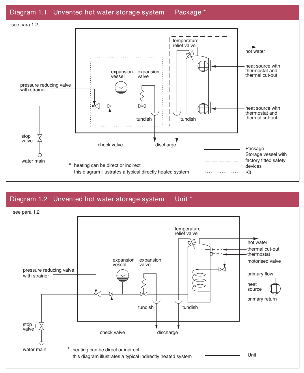
Package – an unvented hot water storage system having factory fitted safety devices together with a kit containing pressure and other devices supplied by the package manufacturer, to be fitted by the installer (see Diagram 1.1).
Unit – an unvented hot water storage system having safety devices and all other devices factory fitted by the unit manufacturer (see Diagram 1.2).
Unvented hot water storage system – includes a system with an unvented vessel for either –
(a)storing domestic hot water for subsequent use; or
(b)heating domestic hot water as it passes through an integral coil or pipe
(e.g. water jacketed tube heater or combi boiler).
Limitation on heating sources
1.3An unvented hot water storage system should not be heated –
(a)directly by a solid fuel heating appliance; or
(b)indirectly by a sealed primary circuit which is heated by a solid fuel heating appliance.
Installation
1.4The installation must be carried out by a person holding a current Registered Operative Identity Card for the installation of unvented hot water storage systems issued by –
(a)the Association of Installers of Unvented Hot Water Storage Systems (Scotland and Northern Ireland);
(b)the Institute of Plumbing;
(c)the Construction Industry Training Board; or
(d)an equivalent body.
Page 11
#Source page 11
Diagram 1.1 Unvented hot water storage system Package *
SYSTEMS WITH A STORAGE VESSEL UP TO 500 LITRES AND 45 KW
#Source page 12
Section 2 Unvented hot water storage systems
2.1To minimise the danger from excessive pressure, unvented hot water storage systems should incorporate a minimum of two independent safety devices in addition to any thermostat provided to control the desired temperature of the stored water.
The selection of safety devices should take account of the physical location of the devices, and the design, configuration, location of components and performance characteristics of the system to which they are attached.
2.2One approach might consist of –
(a)a non selfresetting energy cutout to disconnect the supply of heat to the storage vessel in the event of the storage system overheating; and
(b)a temperature relief valve or a combined temperature and pressure relief valve to safely discharge the water in the event of serious overheating.
Alternative approaches that provide an equivalent degree of safety may be acceptable.
2.3Temperature relief valves and combined temperature and pressure relief valves should not be used in systems which have no provision to automatically replenish the stored water (e.g. unvented primary thermal storage vessels). In such cases there should be a second non selfresetting energy cutout independent of the one provided at paragraph 2.2(a).
2.4Any product designed and manufactured to comply with the requirements of a European Council Directive [e.g. 97/23/EC (Pressure Equipment Directive) or 2009/142/EC (Gas Appliances Directive), implemented by the Gas Appliances (Safety) Regulations 1995 (SI 1995/1629)], does not have to comply with any other standard or part of a standard, whether British, International or other which relates to the same characteristic or specific purpose as the EC Directive.
SYSTEMS WITH A STORAGE VESSEL UP TO 500 LITRES AND 45 KW
2.5The guidance under this heading contains provisions for an unvented hot water storage system, whether heated directly or indirectly, having a storage vessel which has a capacity of not more than 500 litres and a power input of not more than 45 kW.
Unvented hot water storage systems
2.6An unvented hot water storage system should –
(a)comply with BS 6700+ A1 or BS EN 12897;
(b)be a unit or package which has been certified –
(i)as meeting the relevant requirements of regulation 88 by a member body of the European Organisation for Technical Approvals (EOTA) operating a Technical Approvals Scheme
•(e.g. the British Board of Agrément under MOAT 38: 1986); or
Control on heating sources
#Source page 13
(ii)by a certification body having National Accreditation Council for Certification Bodies (NACCB) accreditation as complying with BS EN 12897;
(c)have controls over the heating source or sources complying with paragraph 2.7;
(d)have a tundish or tundishes complying with paragraph 2.13; and
(e)have a suitable discharge pipe or pipes complying with paragraphs 2.14 to 2.17.
Control on heating sources
2.7Devices to control the heating source or sources should be supplied by the manufacturer as part of the unit or package, and should comply with paragraphs 2.9 and 2.10.
However, an indirectly heated system, which incorporates a boiler, may have the thermal cutout on the boiler.
SYSTEMS WITH A STORAGE VESSEL OVER 500 LITRES OR OVER 45 KW
2.8An unvented hot water storage system, whether heated directly or indirectly, having a storage vessel which has a capacity of more than 500 litres or a power input of more than 45 kW will generally be an individual design for a specific project.
The system should generally comply with BS 6700+ A1 or BS EN 12897, as qualified by paragraphs 2.9 to 2.13.
Safety devices
Temperature
2.9An unvented hot water storage system should have the following safety devices to limit the temperature of the stored water –
(a)a non selfresetting thermal cutout on each heating source, complying with either –
(i)BS EN 60335273+ A2; or
(ii)BS EN 257, when the stored water is heated by a gas burning appliance; and
(b)one or more temperature relief valves to BS 6283 Part 2 or BS EN 1490 which have a total discharge capacity (measured in accordance with Appendix F of BS 6283: Part 2 or BS EN 1490) at least equal to the power input to the water.
These safety devices should be factory fitted and located directly on the storage vessel, operate in sequence as the temperature rises and be additional to any thermostatic device fitted to control the temperature of the stored water.
Pressure devices
#Source page 14
2.10Where the system is indirectly heated the non selfresetting thermal cutout should be wired to a motorised valve or some other device which is –
(a)approved by a member of EOTA; or
(b)approved by a body having NACCB accreditation,
as being capable of shutting off the flow to the primary heater.
However, an indirectly heated system, which incorporates a boiler, may have the thermal cutout on the boiler.
Pressure devices
2.11An unvented hot water storage system should have the following devices to control the pressure within the system –
(a)a pressure reducing valve complying with BS EN 1567; and
(b)an expansion valve complying with BS EN 1491.
Other devices
2.12An unvented hot water storage system should also have –
(a)a check valve complying with BS EN 13959 to prevent the expansion of water to the cold supply; and
(b)an expansion vessel complying with BS 6144 sized to accommodate all the expansion of the water on heating.
Tundishes
2.13Each temperature relief valve and expansion valve should discharge through a metal pipe either individually, or via a manifold, to a tundish incorporating an air break.
Where the discharge is individual, the pipe size between the valve and the tundish, should be not less than the nominal outlet size of the valve.
Where a manifold is used it should be so sized that it can accept the total discharges from the valves connected to it.
Where discharges from safety devices may not be apparent (i.e. in dwellings occupied by people with impaired vision or mobility), consideration should be given to the installation of a suitable safety device to warn when discharge takes place (e.g. electronically operated).
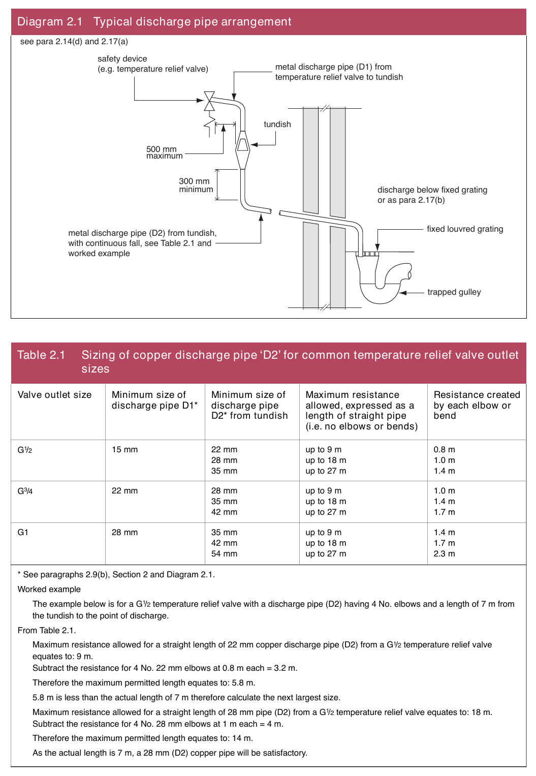
The tundish should be located –
(a)vertically;
(b)not more than 500 mm horizontally from any valve discharging to it;
(c)where it can be readily seen but not create a hazard; and
(d)in the case of a temperature relief valve – in the same space as the storage vessel.
The tundish should be connected to a discharge pipe complying with paragraphs 2.14 to 2.17.
General
#Source page 15
DISCHARGE PIPES FROM TUNDISHES
General
2.14A discharge pipe from a tundish should –
(a)be made of –
(i)metal; or
(ii)other material that has been demonstrated to be capable of safely withstanding the temperatures of the water discharged and is clearly and permanently marked to identify the product and performance standard (e.g. as specified in the relevant part of BS 72911);
(b)be at least one pipe size larger than the outlet from the safety device or manifold discharging to the tundish;
(c)be no longer than the equivalent in hydraulic resistance of a straight 9 m length of pipe unless its size is increased in accordance with paragraph 2.15;
(d)have a vertical section of not less than 300 mm long below the tundish before any elbows or bends in the pipework (see Diagram 2.1); and
(e)have a continuous fall.
2.15In calculating the hydraulic resistance of a discharge pipe the resistance of straight lengths, elbows and bends should be taken into account.
If a discharge pipe is of copper its size should be calculated using the values given in Table 2.1 and the method shown in the worked example.
Visibility of discharge
2.16The discharge from a safety device which may consist of scalding water and steam, should be visible at the tundish and should also be visible at the final point of discharge.
2.17Acceptable discharge arrangements include –
(a)below a fixed louvred grating and above the water seal in a trapped gulley (see Diagram 2.1); or
(b)downward discharge at low level but no less than 100 mm above external surfaces and having a wire cage or suitable guard to prevent contact.
Where a number of discharge pipes are grouped together each discharge pipe should be marked to make the system which is discharging readily identifiable.
Page 16
#Source page 16
Diagram 2.1 Typical discharge pipe arrangement
| Valve outlet size | Minimum size of discharge pipe D1* | Minimum size of discharge pipe D2* from tundish | Maximum resistance allowed, expressed as a length of straight pipe (i.e. no elbows or bends) | Resistance created by each elbow or bend |
|---|---|---|---|---|
| G¹/2 | 15 mm | 22 mm 28 mm 35 mm | up to 9 m up to 18 m up to 27 m | 0.8 m 1.0 m 1.4 m |
| G ³/4 | 22 mm | 28 mm 35 mm 42 mm | up to 9 m up to 18 m up to 27 m | 1.0 m 1.4 m 1.7 m |
| G1 | 28 mm | 35 mm 42 mm 54 mm | up to 9 m up to 18 m up to 27 m | 1.4 m 1.7 m 2.3 m |
| * See paragraphs 2.9(b), Section 2 and Diagram 2.1. Worked example The example below is for a G ¹/2 temperature relief valve with a discharge pipe (D2) having 4 No. elbows and a length of 7 m from the tundish to the point of discharge. From Table 2.1. Maximum resistance allowed for a straight length of 22 mm copper discharge pipe (D2) from a G ¹/2 temperature relief valve equates to: 9 m. Subtract the resistance for 4 No. 22 mm elbows at 0.8 m each = 3.2 m. Therefore the maximum permitted length equates to: 5.8 m. 5.8 m is less than the actual length of 7 m therefore calculate the next largest size. Maximum resistance allowed for a straight length of 28 mm pipe (D2) from a G ¹/2 temperature relief valve equates to: 18 m. Subtract the resistance for 4 No. 28 mm elbows at 1 m each = 4 m. Therefore the maximum permitted length equates to: 14 m. As the actual length is 7 m, a 28 mm (D2) copper pipe will be satisfactory. |
Prevention of excessive domestic hot water temperatures
#Source page 17
Section 3 Reducing the risk of scalding
Prevention of excessive domestic hot water temperatures
3.1Where the operating temperature of domestic hot water in the storage vessel in a dwelling is capable of exceeding 80 ºC under normal operating conditions (a situation that may occur in vessels used as heat stores and those connected to solar heat collectors or solid fuel boilers that do not have intervening controls between the boiler and the vessel containing the hot water) the outlet from the storage vessel should be fitted with a device, such as an inline hot water supply tempering valve in accordance with BS EN 15092. The inline hot water tempering valve should be set/adjusted to ensure that the temperature supplied to the domestic hot water distribution system does not exceed 60 ºC.
Reducing the risk of scalding at bath
3.2The hot water supply temperature to a bath should be limited to a maximum of 48 ºC by the use of an inline blending valve or other appropriate temperature control device, with a maximum temperature stop and a suitable arrangement of pipework.
3.3The acceptability of inline blending valves can be demonstrated by compliance with the relevant harmonised European Standard such as BS EN 1111 or BS EN 1287 to demonstrate that the maximum temperature of 48 ºC cannot be exceeded in operation and that the product will failsafe
(i.e. not discharge water above the maximum temperature). Such valves should not be easily altered by building users.
3.4Inline blending valves and composite thermostatic mixing valves (TMVs) should be compatible with the sources of hot and cold water that serve them.
3.5The length of supply pipes between inline blending valves and final outlets should be kept to a minimum in order to prevent colonisation by waterborne pathogens. Where intermittent use of a bath is anticipated, consideration should be given to high temperature flushing to allow for pasteurisation of the pipes and outlet fittings. This should be configured and operated in such a manner that prevents inadvertent high temperature use.
3.6Further guidance on the use of inline blending valves can be found in BRE Information paper IP14/03 Preventing hot water scalding in bathrooms: using TMVs.
British Standards
#Source page 18
Appendix Publications referred to
British Standards
BS EN 257: 2010 Mechanical thermostats for gasburning appliances.
BS EN 1111: 1999 Sanitary tapware. Thermostatic mixing valves (PN 10). General technical specification.
BS EN 1287: 1999 Sanitary tapware. Low pressure thermostatic mixing valves. General technical specification.
BS EN 1490: 2000 Building valves. Combined temperature and pressure relief valves. Tests and requirements.
BS EN 1491: 2000 Building valves. Expansion valves. Tests and requirements.
BS EN 1567: 1999 Building valves. Water pressure reducing valves and combination water reducing valves. Requirements and tests.
BS EN 12897: 2006 Water supply. Specification for indirectly heated unvented (closed) storage water heaters.
BS EN 13959: 2004 Antipollution check valves. DN 6 to DN 250 inclusive Family E type A, B, C and D.
BS EN 15092: 2008 Building Valves.
BS EN 60335273: 2003+ A2: 2009 Household and similar electrical appliances. Safety. Particular requirements for fixed immersion heaters.
BS 6144: 1990 Specification for expansion vessels using an internal diaphragm, for unvented hot water supply systems.
BS 6283: Safety and control devices for use in hot water systems.
Part 2: 1991 Specification for temperature relief valves for pressures from 1 bar to 10 bar.
BS 6700: 2006+ A1: 2009 Design, installation, testing and maintenance of services supplying water for domestic use within buildings and their curtilages. Specification.
BS 72911: 2006 Thermostatic pipes and fittings for hot and cold water for domestic purposes and heating installations in buildings. General requirements.
Other publications
British Board of Agrément MOAT 38: 1986 The Assessment of Unvented Hot Water Storage Systems and the Approval and Surveillance of Installers.
BRE Information paper IP14/03 Preventing hot water scalding in bathrooms: using TMVs.
Technical Booklet B: 2012 – Materials and workmanship
Technical Booklets
#Source page 19
The following list comprises the series of Technical Booklets prepared by the Department for the purpose of providing practical guidance with respect to the technical requirements of the Building Regulations (Northern Ireland) 2012.
Technical Booklet B Materials and workmanship
Technical Booklet C Site preparation and resistance to contaminants and moisture Technical Booklet D Structure
Technical Booklet E Fire safety
Technical Booklet F1 Conservation of fuel and power in dwellings
Technical Booklet F2 Conservation of fuel and power in buildings other than dwellings Technical Booklet G Resistance to the passage of sound
Technical Booklet H Stairs, ramps, guarding and protection from impact Technical Booklet J Solid waste in buildings
Technical Booklet K Ventilation
Technical Booklet L Combustion appliances and fuel storage systems Technical Booklet N Drainage
Technical Booklet P Sanitary appliances, unvented hot water storage systems and reducing the risk of scalding Technical Booklet R Access to and use of buildings
Technical Booklet V Glazing
Any person who intends to demonstrate compliance with the Building Regulations by following the guidance given in a Technical Booklet is advised to ensure that the guidance is current on the date when the plans are deposited or notice given to the district council.