Northern Ireland Technical booklet R
Technical booklet R - Access to and use of buildings - October 2012
Library captured 10 September 2026 · Source updated 22 August 2026
● Finance and ● Personnel
#Source page 1
Department of
● Finance and ● Personnel
G u i d a n c e
Te c h n i c a l B o o k l e t
R
Access to and use of buildings
October 2012
Page 2
#Source page 2
Contents page
Introduction 4
Technical Booklets 4
This Technical Booklet 4
Protected buildings 5
Other legislation 5
Part R Regulations 6
Guidance Performance and introduction to provisions 8
Section 1 General
Definitions 10
The principles of inclusive design within the built environment 11
Buildings other than dwellings 12
Dwellings 13
Visual contrast 13
Access statements 14
Buildings other than dwellings: Section 2 to Section 6
Section 2 Access to buildings other than dwellings
General 16
Approach to buildings 16
Level approach 17
Hazards on access routes 19
Section 3 Access into buildings other than dwellings
General 20
Accessible entrances 20
Doorways to accessible entrances 21
Page 3
#Source page 3
Manually operated entrance doors to accessible entrances 22
Power operated entrance doors to accessible entrances 23
Glazed entrance doors and glazed screens to accessible entrances 25
Entrance lobbies to accessible entrances 25
Section 4 Access within buildings other than dwellings
Horizontal circulation 27
Corridors and passageways 27
Internal lobbies 28
Internal doors 28
Vertical circulation 31
Vertical access between storeys 31
Lifting devices 31
Passenger lifts 32
Lifting Platforms 34
Section 5 Facilities in buildings other than dwellings
General 35
Reception 35
Audience seating 36
Refreshment facilities 39
Guest bedrooms 41
Wheelchair accessible changing facilities 44
Outlets, switches and controls 46
Aids to communication 49
Section 6 Sanitary accommodation and associated sanitary facilities in buildings other than dwellings
General 50
Sanitary accommodation 51
Wheelchair accessible unisex sanitary accommodation 56
Traditional separate sex sanitary accommodation 57
Shower and bath facilities 58
Page 4
#Source page 4
Dwellings and blocks of dwellings: Sections 7 to Section 11
Section 7 Means of access to and into a dwelling
Access to the dwelling 66
External approach 67
Access into the dwelling 67
Section 8 Circulation within a dwelling
General 69
Horizontal circulation 69
Vertical circulation 70
Section 9 Circulation within common areas of a block of dwellings
General 71
Horizontal circulation 71
Vertical circulation 71
Section 10 Sanitary convenience in a dwelling
General 73
Access to sanitary conveniences 73
Section 11 Heights of socket outlets, switches, etc. in a dwelling
Heights of outlets and switches 75
Appendix A Informative – Facilities for people with profound and multiple learning disabilities 76
Appendix B Publications referred to 77
Technical Booklets
#Source page 5
Introduction
Technical Booklets
This Technical Booklet, which takes effect on 31st October 2012, is one of a series that has been prepared by the Department of Finance and Personnel (the Department) for the purpose of providing practical guidance with respect to the technical requirements of the Building Regulations (Northern Ireland) 2012 (the Building Regulations).
At the back of each Technical Booklet is a list of all the Technical Booklets that have been prepared and published by the Department for this purpose.
The guidance given in a Technical Booklet includes performance standards and design provisions relating to compliance with specific aspects of the Building Regulations for the more common building situations.
If the guidance in a Technical Booklet is followed there will be a presumption of compliance with the requirements of those Building Regulations covered by that guidance. However, this presumption can be overturned, so simply following the guidance does not guarantee compliance. For example, if a particular circumstance is not one of the more common building situations the design provisions given in the Technical Booklet may not be appropriate.
There are likely to be alternative ways of demonstrating compliance with the relevant requirements of the Building Regulations other than by following a design provision given in a Technical Booklet. There is therefore no obligation to adopt any particular provision set out in a Technical Booklet, should you decide to comply in some other way. However, you will have to demonstrate that your alternative solution meets the relevant requirements of the Building Regulations by those other means.
This Technical Booklet
Requirements
The guidance contained in this Technical Booklet relates only to the requirements of regulations 91, 92, 93 and 94. The work will also have to comply with all other relevant requirements of the Building Regulations.
Materials and workmanship
Any building work which is subject to requirements imposed by Part A of the Building Regulations should be carried out in accordance with regulation 23 of those regulations. Guidance on meeting these requirements for materials and workmanship is given in Technical Booklet B which supports Part B.
The Building Regulations are made for specific purposes, primarily securing the health, safety, welfare and convenience of people and for the conservation of fuel and power. Standards and technical approvals are relevant guidance to the extent that they relate to these purposes. However, they may also address other aspects of performance such as serviceability, or aspects which although they relate to health and safety are not covered by the Building Regulations.
Named standards
#Source page 6
Where this Technical Booklet makes reference to a named standard, the relevant version of the standard is the one listed in Appendix B. However, if this version has been replaced or updated by the issuing standards body, the new version may be used as a source of guidance provided that it continues to address the relevant requirements of the Building Regulations.
Diagrams
The diagrams in this Technical Booklet supplement the text. They do not show all the details of construction and are not intended to illustrate compliance with any other requirement of the Building Regulations. They are not necessarily to scale and should not be used as working details.
Protected buildings
District councils have a duty to take account of the desirability to preserve the character of protected buildings when carrying out their functions under Building Regulations. Therefore, where work is to be carried out to a protected building to comply with Part R or any other Part of the Building Regulations, special consideration may be given to the extent of such work for compliance where it would unacceptably alter the character or appearance of the building. Protected buildings are defined in Article 3A(2) of the Building Regulations (Northern Ireland) Order 1979 (as amended).
Other legislation
The provisions of this Technical Booklet relate to the requirements of Building Regulations and do not include measures which may be necessary to meet the requirements of other legislation. Such other legislation may operate during the design or construction stages or when a building is brought into use and can extend to cover aspects which are outside the scope of the Building Regulations.
The Workplace (Health, Safety and Welfare) Regulations (Northern Ireland) 1993
The Workplace (Health, Safety and Welfare) Regulations (Northern Ireland) 1993 (the Workplace Regulations) contain some requirements which affect building design. The main requirements are now covered by the Building Regulations, but for further information see – The Workplace Regulations and the Workplace Health, Safety and Welfare Approved Code of Practice and Guidance published by TSO.
The Workplace Regulations apply to the common parts of flats and similar buildings if people such as cleaners, wardens and caretakers are employed to work in these common parts. Where the requirements of the Building Regulations that are covered by Part R do not apply to dwellings, the provisions may still be required in the situations described above in order to satisfy the Workplace Regulations.
PART R
#Source page 7
Part R Regulations
Part R (comprising regulations 90 to 94) of the Building Regulations, which sets out the requirements for access to and use of buildings, has been replicated below for the convenience of the user of this Technical Booklet and is taken directly from the Building Regulations (Northern Ireland) 2012.
Any person who intends to demonstrate compliance with the Building Regulations by following the guidance given in this Technical Booklet is advised to ensure that the regulations below, are current on the date when plans are deposited or notices given to the district council.
As Part A (comprising regulations 1 to 21) of the Building Regulations sets out the interpretation along with the procedural requirements relating to the application of the regulations, the Department advises that all Parts of the Building Regulations are read in conjunction with Part A of those regulations.
The Building Regulations (Northern Ireland) 2012 and any subsequent amendment may be viewed by following the links from the Department’s website at “www.buildingregulationsni.gov.uk”.
PART R
Access to and use of buildings
Application and interpretation
90.—(1) Subject to paragraphs (2), (3) and (4) this Part shall apply to any building or part of a building.
(2)This Part shall not apply to—
(a)any garage or outbuilding associated with a dwelling;
(b)any part of a building which is used solely to enable the building or any service or fitting in the building to be inspected, maintained or repaired; and
(c)the alteration or extension of an existing dwelling to which this Part did not apply when the dwelling was erected other than where the alteration or extension affects a facility suitable for use by people with an impairment of mobility, hearing or sight, in the existing building.
(3)The requirements of regulation 92 shall not apply to—
(a)a dwelling; and
(b)any building that is being extended where reasonable provision for access to the extension is provided through the building being extended.
(4)The requirements of regulation 93 shall not apply to—
(a)a dwelling; and
(b)an extension to a building where there is provision for suitable sanitary accommodation in the building being extended and all users of the extension can gain access to and use that sanitary accommodation.
Access and use
#Source page 8
(5)In this Part— “Dwelling” means a house or flat; “Entrance storey” in a dwelling means the storey which contains the principal entrance for
the dwelling; “Independent access” to a part of or extension to a building means a route of access to that part or extension which does not require the user to pass through any other part of the building; “Principal entrance” in relation to a dwelling means the entrance a visitor (not familiar with the dwelling) will normally expect to use to enter it;
“Principal storey” in a dwelling means the storey nearest to the entrance storey which contains a habitable room, or if there are two such storeys equally near, either such storey; “Sanitary accommodation” has the meaning assigned to it by regulation 84 in Part P; and “Sanitary convenience” means a water closet and washbasin.
Access and use
91.Reasonable provision shall be made for people to have access to, into, within and to use a building and its facilities:
Provided that in a dwelling this requirement shall be limited to the entrance storey or, where that storey contains no habitable room, to the principal storey.
Access to extensions
92.Reasonable provision shall be made for independent access to an extension to a building.
Sanitary accommodation in extensions
93.Where sanitary accommodation is provided in a building, reasonable provision shall be made for the provision of suitable sanitary accommodation in any extension to the building.
Sanitary conveniences in dwellings
94.In a dwelling a sanitary convenience shall be provided—
(a)in the entrance storey; or
(b)where the entrance storey contains no habitable rooms – in the principal storey.
Performance to satisfy regulations 91, 92, 93 and 94 in Part R
#Source page 9
Guidance Performance and introduction to provisions
Performance to satisfy regulations 91, 92, 93 and 94 in Part R
0.1It is the view of the Department that the requirements of Part R will be met by making reasonable provision to ensure that buildings are accessible and usable.
In buildings other than dwellings, people, regardless of ability, age or gender, should be able to gain access to, into and within buildings and use their facilities, as customers, visitors and people who work in them.
In dwellings, all visitors should be able to –
(a)get access to and into the dwelling;
(b)access and use habitable rooms within the principal storey; and
(c)access and use a sanitary convenience in the dwelling.
Making provisions to facilitate people with a disability who may visit a dwelling is also expected to enable occupants with disabilities to cope better with reduced mobility and to “stay put” longer in their own homes. It is not expected to facilitate fully independent living for all people with disabilities.
Buildings other than dwellings
Introduction to provisions in Section 2
0.2The guidance in Section 2 is to ensure a suitable and convenient means of access to a building for people from the boundary and from car parking provided on site.
Provisions are also given for uncontrolled carriageway crossings and avoiding hazards on access routes.
Introduction to provisions in Section 3
0.3The guidance in Section 3 is to assist people to be able to identify the building entrance and use it to enter the building easily, conveniently and without the risk of injury.
Introduction to provisions in Section 4
0.4The guidance in Section 4 is to facilitate the movement of people within a building both within a storey (horizontal circulation) and between storeys (vertical circulation).
Introduction to provisions in Section 5
0.5
The guidance in Section 5 is to ensure that people have access to and use of all the facilities provided in a building.
Introduction to provisions in Section 6
#Source page 10
0.6The guidance in Section 6 is to ensure that sanitary accommodation and associated sanitary facilities provided in a building, are no less available for people with a disability than for nondisabled people. Appropriate solutions to sanitary accommodation may vary depending on the size, scale, nature and intended use of the building.
Dwellings
Introduction to provisions in Section 7
0.7The guidance in Section 7 is to facilitate people with a range of abilities to approach and gain access into a dwelling and to a common entrance of a block of dwellings e.g. flats, from the boundary or the point of alighting from a vehicle on a driveway within the plot.
Introduction to provisions in Section 8
0.8The guidance in Section 8 is to facilitate access into habitable rooms and to a sanitary convenience in the entrance storey or the principal storey of the dwelling.
Introduction to provisions in Section 9
0.9In a block of dwellings e.g. flats, the guidance is to ensure reasonable provision for people with a disability to visit occupants who live on any storey.
Introduction to provisions in Section 10
0.10The guidance in Section 10 is to provide a sanitary convenience which a disabled visitor to the dwelling may use. The sanitary convenience should normally be located in the entrance storey. Where the entrance storey contains no habitable rooms, a sanitary convenience should be provided in the principal storey.
Introduction to provisions in Section 11
0.11The guidance in Section 11 is to assist those people whose reach is limited, to use a dwelling more easily, by locating switches, sockets, etc. at suitable heights.
Definitions
#Source page 11
Section 1 General
Definitions
1.1
In this Technical Booklet the following definitions apply – Access – approach or entry. Accessible – suitable access to and usable by all people, regardless of their ability.
Dwelling – has the meaning assigned to it by regulation 90 in Part R of the Building Regulations. Entrance storey in a dwelling – has the meaning assigned to it by regulation 90 in Part R of the Building Regulations.
Boundary – the boundary of the land (excluding any abutting street, canal or river) on which the building is erected. Flat – has the meaning assigned to it by regulation 2 in Part A of the
Building Regulations.
Isolator – a switch used to cut off the supply of electricity to an electrical appliance for maintenance purposes. Incorporated changing facility – an accessible changing facility contained within and open to the communal changing facility.
Incorporated shower facility – an accessible shower facility contained within and open to the communal shower facility. Level approach – (with respect to the approach to a building) an access route that is predominately level, but may contain a gradient less steep than 1 in 20 in the direction of travel.
Lifting device – a passenger lift or a lifting platform. Plot – the area within the boundary of the land on which the building is erected.
Plot gradient – the gradient measured along the route of travel between the point of entry and the floor level at –
(a)the principal or an alternative entrance to a dwelling; or
(b)the common entrance or an alternative entrance to a block of dwellings.
Point of entry – the point at which a person visiting the building either –
(a)normally enters the plot; or
(b)alights from a vehicle within the plot.
Principal entrance (in buildings other than a dwelling or a block of dwellings) – the entrance a visitor or customer (not familiar with the building) would normally expect to use to enter it.
The principles of inclusive design within the built environment
#Source page 12
Principal entrance (in relation to a dwelling) – has the meaning assigned to it by regulation 90 in Part R of the Building Regulations.
Principal entrance storey – the storey or storeys where the principal entrance or entrances are located. If an alternative accessible entrance is to be provided by virtue of paragraph 3.1 the storey containing that entrance is a principal entrance storey.
Principal storey in a dwelling – has the meaning assigned to it by regulation 90 in Part R of the Building Regulations.
Sanitary accommodation – has the meaning assigned to it by regulation 84 in Part P of the Building Regulations.
Sanitary convenience – has the meaning assigned to it by regulation 90 in Part R of the Building Regulations.
Suitable – (with respect to means of access and facilities) designed for use by people regardless of their ability.
Surface width – the width of a stair or ramp, measured at the tread of a flight or the surface of a ramp, between any enclosing walls, strings, upstands, kerbs or guarding.
Terminal fitting – a water outlet device providing water to a sanitary appliance.
Usable (with respect to buildings and parts of buildings) – convenient for independent use.
Wheelchair accessible – suitable access to and usable by wheelchair users.
The principles of inclusive design within the built environment
1.2An inclusive environment is one that can be used by everyone, regardless of age, gender or ability. Buildings designed to be inclusive should be safe, convenient, sustainable and usable by all people.
The scope of this Technical Booklet is to give provisions for generic solutions to the more common building scenarios to enable people to –
(a)get access to a building;
(b)get into a building;
(c)move around all floors of a building; and
(d)get access to and use the facilities (toilets, changing rooms, showers etc.) that are provided in a building.
The methods and standards within this Technical Booklet relate, in the main, but not exclusively, to the provision of design features and sufficient space, to make it possible for people with disabilities to independently access and use a building.
Buildings other than dwellings
#Source page 13
1.3The provisions for access to and use of a building are for the benefit of people who are customers or visitors to the building or who work in it.
1.4An extension should be treated in the same manner as a new building. The extension should –
(a)be independently approached and entered from the boundary and from car parking within this boundary; or
(b)have suitable access provided through the building being extended.
Where sanitary accommodation is provided in a building that is being extended –
(c)then suitable sanitary accommodation should be provided within the extension; or
(d)the existing sanitary accommodation should also be suitable and accessible by the users of the extension.
1.5When a building is altered the alterations must comply with the requirements of Regulation 91 in Part R. The building, including access to it from the boundary and from on site car parking, where provided, must be no less accessible after completion of the alterations than it was before the work was carried out.
1.6When a building undergoes a material change of use so that it is used as a hotel or boarding house, an institution, a place of assembly or recreation, or a shop it should be treated in the same manner as a new building.
When a part of a building undergoes a material change of use so that it is used as a hotel or boarding house, an institution, a place of assembly or recreation, or a shop it should –
(a)be independently approached and entered or have suitable access provided through the building; and
(b)have any sanitary accommodation that is provided for or in connection with that part accessible (from that part) and usable. If sanitary accommodation is not provided as part of any works in relation to the material change of use and if users of that part of the building have use of sanitary accommodation elsewhere in the building then people should be able to gain access to, and use that sanitary accommodation.
1.7Part R is limited to matters of access to, into, within, and use of a building. It does not extend to means of escape for a person with a disability in the event of fire, for which reference should be made to Part E (Fire safety).
This Technical Booklet, gives guidance on the strategy for access to and within a building other than a dwelling. When this strategy includes the use of ramps and/or stairs, such ramps or stairs must satisfy the relevant requirements of Part H.
Dwellings
#Source page 14
1.8The provisions for access and for facilities within dwellings are for the benefit of people who are disabled who may visit the dwelling.
Where Part R applies, reasonable provision should be made –
(a)so that people with a disability can reach the principal entrance to the dwelling, or to a common entrance to a block of dwellings, from the boundary or from car parking within this boundary;
(b)for access for people with a disability into and within the entrance storey or the principal storey of the dwelling and to access and use any facilities provided to comply with Part R; and
(c)for sanitary conveniences for use by people with a disability.
Part R does not extend to means of escape for people with a disability in the event of fire, for which reference should be made to Part E (Fire safety).
Part H (Stairs, ramps, guarding and protection from impact) contains provisions for the design of stairs and ramps.
This Technical Booklet, gives guidance on the strategy for access to and within a dwelling. When this strategy includes the use of ramps and/or stairs, such ramps or stairs must satisfy the relevant requirements of Part H.
Visual contrast
1.9Visual contrast is the perception of a difference visually between one element of a building and another by reference to their light reflectance values.
Light reflectance value (LRV) is the total quantity of visible light reflected by a surface at all wavelengths and directions when illuminated by a light source.
For people with adequate vision, differences in the nature or the intensity of colour provide adequate visual contrast. Unfortunately, this is not the case for all people who are visually impaired. The main feature of a surface, which appears to be strongly correlated with the ability of visually impaired people to identify differences in colour, is the LRV. Differences in LRV can be used to assess the degree of visual contrast between the surfaces of elements such as handrails, doors, door furniture, key fittings/fixtures and surrounding surfaces, etc.
The LRV scale runs from 0, which is a perfectly absorbing surface that could be assumed to be totally black, up to 100, which is a perfectly reflective surface that could be considered to be perfect white. Because of practical influences in any application, black is always greater than 0 and white never equals 100.
A difference in LRV of 30 points or more allows a degree of variability that is required to provide reasonable visual contrast.
For flat areas it is thought that LRV differences are less important between two large areas, e.g. between a wall and floor, than between a small object on a larger background surface, e.g. a light switch on a wall.
Access statements
#Source page 15
1.10Access statements are not a requirement of the Building Regulations.
Applicants may wish to satisfy the requirements of Part R by adopting the guidance and provisions of Technical Booklet R. However, they could choose to follow the performance criteria given in paragraph 0.1 and offer alternative design solutions they believe comply with the reasonable provision requirements of the relevant regulation. Evidence to support such an alternative design approach might include –
(a)application of the recommendations in BS 8300 where these differ from the provisions, or are not covered, in this Technical Booklet;
(b)results of current validated research;
(c)outcome of consultations with other parties (e.g. Northern Ireland Environment Agency, Access Officers, local Access Groups, etc.); and
(d)convincing arguments that an alternative solution will achieve the same, a better, or a more convenient outcome.
An access statement setting out the rationale for the access strategy, could be useful in presenting the evidence of the design approach adopted.
In the case of extensions and material changes of use of buildings other than dwellings, and particularly in the case of protected buildings, such a statement will allow an applicant to identify any constraints imposed by the existing structure and its immediate environment and to propose compensatory measures where full access proves to be impracticable or unreasonable. This will allow for an explanation to be provided and assessed in situations where, for example, a less than fully accessible access route is proposed to an extension, or to a building or part of a building subject to a material change of use.
Buildings other than dwellings
#Source page 16
General
#Source page 17
Section 2 Access to buildings other than dwellings
General
2.1As far as possible, the means of access from the point of entrance at the boundary and from car parking designated for people with a disability which is provided within the boundary, to the principal entrance(s) and, where provided, a staff entrance, should be level. However where a difference in level is unavoidable due to site constraints, the approach may have a gentle gradient over a long distance (for all or part/s of the approach), or it may incorporate a number of shorter parts at a steeper gradient, with level areas at intervals as rest points. Generally, gradients within the approach should be as gentle as possible. An approach that contains one or all of these features is called a level approach.
It is recognised that a level approach is not attainable in all situations and therefore, an access route containing a ramp, may be an appropriate solution to suit the site topography.
It is also important that routes between buildings within a complex are also accessible.
To reduce the danger of inadvertently walking into a vehicular access route the approach to a building should be separate from any vehicular route and where possible, not sharing the same surface.
All access routes to principal, or alternative accessible, entrances should be surfaced so that people are able to travel along them easily, without excessive effort and without the risk of tripping or falling.
Potential hazards e.g. from open windows, on or over access routes should also be avoided.
Approach to buildings
2.2The means of access to a building should be by a level approach complying with paragraph 2.8 to 2.12. However, where site constraints necessitate that all or any part of the means of access to or between buildings, contains a gradient of 1 in 20 or steeper, a ramped approach should be provided.
2.3As ramps are not necessarily suitable and convenient for all people it is beneficial to have steps as well as a ramp. For example, some people who can walk but have restricted mobility find it more difficult to negotiate a ramp than a stair. In addition, adverse weather conditions increase the risk of slipping on a ramp.
Where a ramped approach has a rise of 300 mm or more, it should also have complementary steps.
2.4If the total rise of a ramped approach is too high, it can be unacceptably tiring for wheelchair users and some people with walking difficulties, even if a number of rest landings are provided. Therefore, where the access route to the building is, or contains a ramped approach having a total rise of more than 2000 mm, an additional means of access suitable for all people, should also be provided, e.g. a suitable lifting device.
Level approach
#Source page 18
2.5
Where the approach requires to be guarded, that guarding must comply with the relevant requirements of Part H.
2.6
Where there is a complex of buildings within the boundary, a level approach should be provided between buildings to which Part R applies.
2.7
The approach to a building should be separate from any vehicular route.
Level approach
2.8
A level approach should have –
(a)an unobstructed width of not less than 1500 mm. However, at a local obstruction the width may be reduced to 1000 mm, provided that the length of the reduced width is not more than 6 m and the obstruction is protected by a suitable barrier; and
(b)clear headroom of not less than 2100 mm.
Where the level approach has a gradient steeper than 1 in 60 it should have horizontal rest areas, not less than 1200 mm long and a rise of not more than 500 mm between rest areas.
Where the level approach is more than 50 m in length it should have passing places. These should be spaced at a distance of not more than 50 m with a clear line of sight between consecutive passing places. Every passing place should be not less than 1800 mm wide and not less than 2000 mm long therefore, the width of the passing place may include the width of the level approach. A level approach with a surface width of 1800 mm or more can accommodate nonvehicular traffic without the need for passing places.
Where a level approach has a crossfall it should be not steeper than 1 in 40.
2.9The surface of a level approach should –
(a)be firm;
(b)reduce the risk of slipping;
(c)have similar surface frictional characteristics along its length; and
(d)have an even surface finish.
2.10Notwithstanding the provisions of paragraph 2.9(d) –
(a)where formless materials are used as surfacing, any undulations should be not more than 3 mm measured from a point below a 1000 mm straight edge; and
(b)where paving units are used as surfacing material, any difference in level between the units at the joints, should be not more than 5 mm.
2.11Where paving units are used as surfacing material and have –
(a)recessed filled joints, the joints should be not more than 10 mm wide and 5 mm deep; and
(b)unfilled joints, the joints should be not more than 5 mm wide.
Page 19
#Source page 19
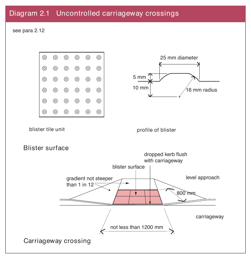
2.12Where a level approach crosses a carriageway at an uncontrolled crossing point, this should be identified by using buff coloured blister type tactile warning paving, having a length of not less than 1200 mm and a width of 800 mm. See Diagram 2.1.
Diagram 2.1 Uncontrolled carriageway crossings
Hazards on access routes
#Source page 20
Generally
2.13Features of a building that occasionally obstruct an access route, particularly if they are partially transparent and therefore indistinct, or cause a danger overhead, should not present a hazard to building users.
Protection from hazards
2.14To reduce hazards on an access route for people including those who are visually impaired, any –
(a)door (other than for emergency use only) which opens outwards;
(b)part of a window, when open in normal use, that projects more than 100 mm; and
(c)other feature of a building which projects,
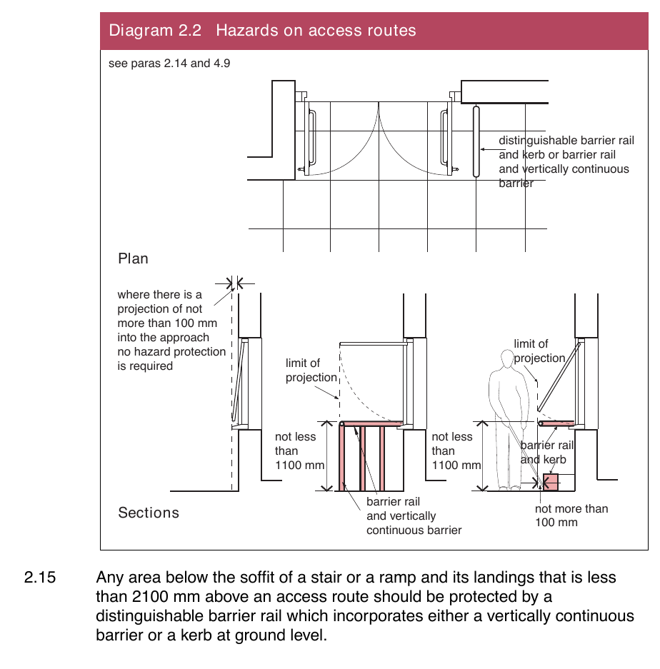
into an access route, should be protected by a distinguishable barrier rail which incorporates either a vertically continuous barrier or a kerb at ground level. See Diagram 2.2.
Diagram 2.2 Hazards on access routes
General
#Source page 21
Section 3 Access into buildings other than dwellings
General
3.1A principal entrance(s) and where provided, one entrance which is specifically for members of staff, and any associated lobby, should be accessible. However, where the space outside the principal or staff entrance is severely restricted, or the slope of the ground does not allow the means of access to the building to be provided in accordance with paragraph 2.2, an alternative accessible entrance, intended for general use, is acceptable, provided there is suitable internal access from that entrance to the principal and staff entrances.
It is important to reduce any risks to people when entering a building, e.g. trip or slips, coming into contact with an open glazed door, etc.
Accessible entrances
3.2Accessible entrances should be clearly signposted and easily recognisable. Any structural elements, for example supports for a canopy, are useful in identifying the entrance, but should not present a hazard.
The route from the exterior across the threshold should provide weather protection, and not present a barrier for wheelchair users or a trip hazard for other people. A level threshold is preferred.
3.3An accessible entrance should be clearly indicated (e.g. by signs incorporating the International Symbol of Access), from –
(a)the point of entrance at the boundary;
(b)suitable car parking which is provided within the boundary;
(c)the principal entrance, where the principal entrance is not an accessible entrance; and
(d)a staff entrance, where that staff entrance is not an accessible entrance.
3.4An accessible entrance should –
(a)be readily apparent (e.g. distinguishable, through suitable visual contrast from that of the adjacent elements of the building); and
(b)have an access area –
(i)that is level. However, where the access area contains a crossfall, it should be not steeper than 1 in 40;
(ii)with a surface that is firm;
(iii) with an unobstructed size of not less than 1500 mm by 1500 mm in front of the accessible entrance; and
(iv) that is at, or about, the level of the floor of the entrance.
3.5When manually operated entrance doors are installed, the area immediately in front of the entrance doors should, where it is practicable, be protected from inclement weather. This will assist people who require extra time to use manually operated doors and may take the form of a canopy or recessed entrance.
Doorways to accessible entrances
#Source page 22
3.6Where an entrance communication system is installed, it should have both video and audio communication to assist people with hearing loss or people who cannot speak.
3.7A floor immediately inside any accessible entrance should –
(a)have a surface which is firm and even;
(b)where there are changes in flooring surface, be at, or about, the level of any adjacent flooring surface; and
(c)have a surface that will reduce the risk of tracking moisture into the building (e.g. from shoes or wheelchair wheels). However, this provision is not required where the external access area is designed and constructed to limit the tracking of moisture into the building.
Doorways to accessible entrances
3.8Doors to the principal entrance or alternative accessible entrance should be accessible to all, particularly wheelchair users and people with limited physical dexterity. Entrance doors may be manually operated without powered assistance, or power operated under manual or automatic control.
Once open, all doors to accessible entrances should be wide enough to allow unrestricted passage for a variety of users, including wheelchair users, people carrying luggage, people with assistance dogs, and people with pushchairs and small children.
3.9An accessible entrance doorway should contain a leaf which provides an effective clear width of not less than that given in column (2) of Table 3.1. This effective clear width applies to a single leaf door or one leaf of a double leaf door. However, where a double leaf door is power operated, the effective clear width may be incorporated between both leaves provided those leaves operate simultaneously.
Where a building is to be altered or undergo a material change of use and the effective clear width given in column (2) of Table 3.1 cannot be achieved, an accessible entrance doorway may contain a leaf which provides an effective clear width of not less than that given in column (3) of Table 3.1.
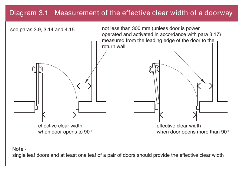
The effective clear width of a doorway should be measured in accordance with Diagram 3.1.
| Table 3.1 Effective clear widths of doorways to accessible entrances | ||
|---|---|---|
| Users of entrance (1) | Effective clear width of doorway in a new building (2) | Effective clear width of doorway in an existing building (3) |
| limited to staff and visitors | 800 mm | 750 mm |
| members of the public | 1000 mm | 775 mm |
Manually operated entrance doors to accessible entrances
#Source page 23
Diagram 3.1 Measurement of the effective clear width of a doorway
3.10An accessible entrance doorway should have a threshold which is level. However, where required due to site location (e.g. to prevent the ingress of moisture), a threshold may contain one or more upstands, provided the cumulative height of these upstands is not more than 15 mm. An upstand more than 5 mm high should have all exposed edges chamfered or rounded.
The route from the access area across the threshold should not present a barrier for wheelchair users or a trip hazard for other people.
3.11A door to an accessible entrance should not project, when open, into an adjacent access route, unless that portion of the door which projects into the access route is protected by a suitable barrier.
Manually operated entrance doors to accessible entrances
3.12Selfclosing devices on manually operated nonpowered swing doors can create difficulties for many people who have limited upper body strength, are pushing prams or are carrying heavy objects.The force needed to open a door and pass through the doorway, against a closing device, should therefore be limited.
A space alongside the leading edge of a door, on the pull side, will enable a wheelchair user to reach and grip the door handle, then open the door without releasing hold on the handle and without the footrest colliding with the return wall.
Door furniture on manually operated nonpowered doors should be easy to operate by people with limited manual dexterity, and be readily apparent to assist visually impaired people.
Power operated entrance doors to accessible entrances
#Source page 24
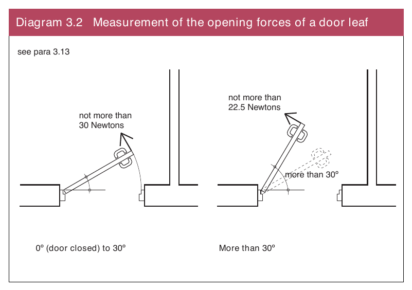
3.13The force required to open a manually operated entrance door should be not more than –
(a)30 Newtons between 0º (door closed) and 30º of the opening arc of the door; and
(b)22.5 Newtons from a point greater than 30º of the opening arc of the door,
measured at the leading edge of the door leaf during the opening action. See Diagram 3.2.
Diagram 3.2 Measurement of the opening forces of a door leaf
3.14A manually operated entrance door should have an unobstructed space of not less than 300 mm, at the leading edge of the door leaf on the pull side. See Diagram 3.1.
3.15Door opening furniture should –
(a) be distinguishable, through suitable visual contrast, from that of the face of the door leaf; and
(b) where the door leaf is fitted with a latch, be operable by a person with limited manual dexterity (e.g. a lever handle).
Power operated entrance doors to accessible entrances
3.16A powered door opening and closing system, either manually controlled or automatically operated by sensors, is the most satisfactory solution for the majority of people. An automatic sliding door arrangement is particularly beneficial as it avoids the risks associated with automatic swing doors and its use can make it possible to reduce the length of any entrance lobby.
Manual controls for powered entrance doors should be distinguishable against their background and located so that a person, having used the control, does not need to move to avoid contact with the door as it opens.
Page 25
#Source page 25
Revolving doors are not considered accessible. They create particular difficulties, and risk of injury, for people with assistance dogs, visually impaired people or those with mobility problems and for people with children and/or pushchairs. If the entrance includes a revolving door, then a door complying with the provisions for manually operated or power operated entrance doors should be provided immediately adjacent to it.
3.17A power operated entrance door should have a sliding, swinging or folding action that is activated –
(a)manually by a push pad, electronic card, coded entry, or by remote activation; or
(b)automatically (e.g. by a motion detector).
3.18Any manual controls to operate a powered entrance door should comply with the requirements of paragraph 5.40 and 5.44(g) (see Diagram 5.8(b)).
3.19Where a power operated entrance door has a swing action, indication of its operation and direction of swing should be provided to the side that the door opens towards.
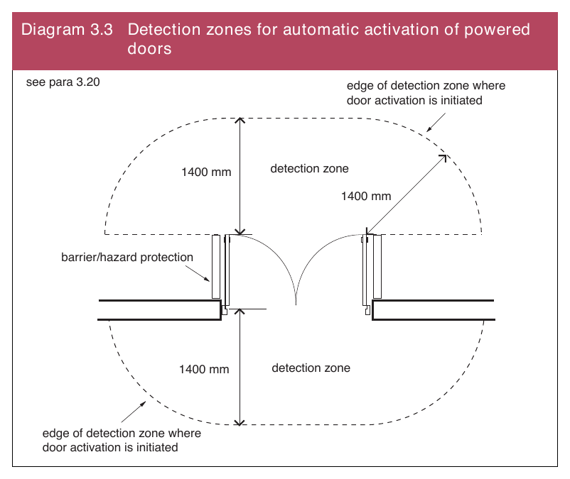
3.20Where a power operated entrance door has an automatic activation device, it should be positioned so that the edge of the detection zone, where activation is initiated, is 1400 mm from –
(a)the door, measured perpendicular to the plane of the closed door, when the door opens away from the user; and
(b)the leading edge of the door in the fully open position, when the door opens towards the user.
See Diagram 3.3.
Diagram 3.3 Detection zones for automatic activation of powered
Glazed entrance doors and glazed screens to accessible entrances
#Source page 26
3.21Visually impaired people should be in no doubt as to the location of glass entrance doors, especially when the doors are within a glazed screen.
The presence of the door should be apparent when it is shut and also when open. Where it can be held open, measures should be taken to avoid people being harmed by walking into the door.
In addition to meeting the requirements of Part R, glazed doors and screens must also comply with the relevant requirements of Part V.
3.22Where an entrance door is manufactured from transparent or translucent materials and –
(a)forms part of, or is adjacent to, a glazed screen, it should have its top and side face edges distinguishable, through suitable visual contrast, from that of the glazed screen; and
(b)is designed and installed to be capable of being held open, the leading edge of the door should be protected by a suitable distinguishable barrier when in the held open position.
Entrance lobbies to accessible entrances
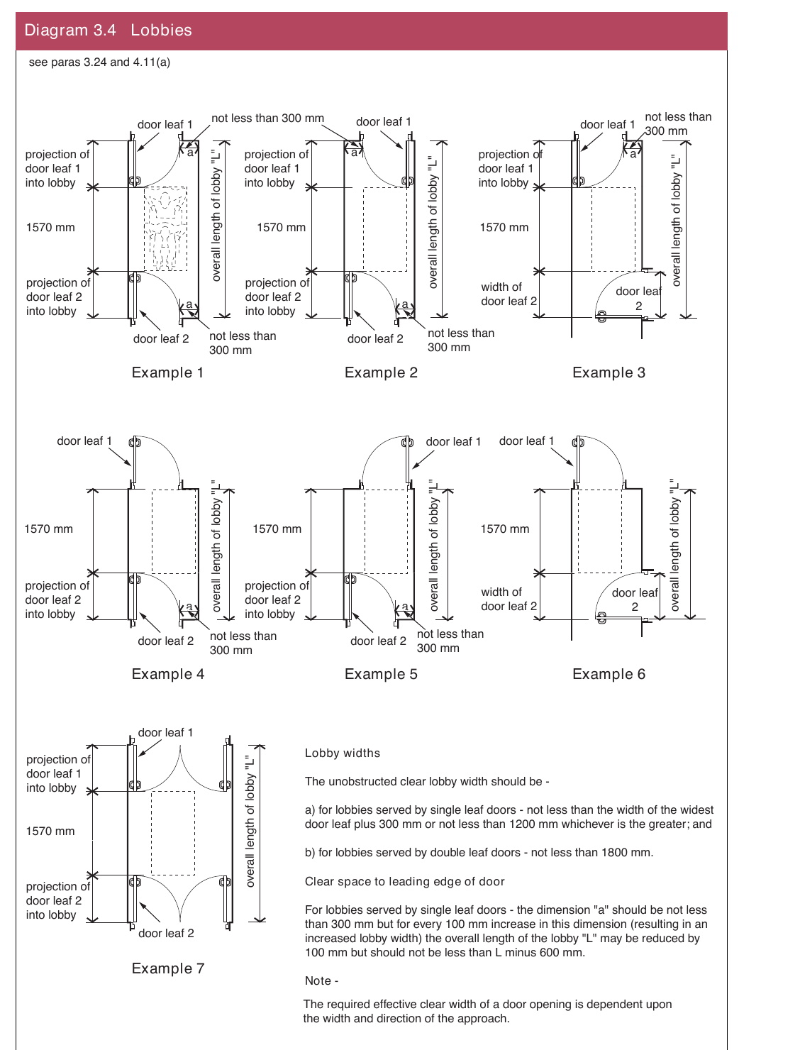
3.23An entrance lobby should be large enough and of a shape to allow a wheelchair user along with a companion or a person pushing a pram to move clear of one door before opening a second door. The minimum length of the lobby is related to door size, door swing, the projection of the door into the lobby and the size of an occupied wheelchair with a companion pushing. Where both doors of a lobby are automatic sliding doors, the length can be reduced as no door swings are involved, nor is space required for manual operation. Similarly, if ‘reduced swing’ door sets are used, the length can be reduced because the projection of the door into the lobby is reduced.
3.24An entrance lobby should –
(a)have the minimum dimensions shown in Diagram 3.4, clear of any projections (including any handrail), into the lobby; and
(b)have a floor that complies with the provisions of paragraph 3.7.
3.25Any door to and within any entrance lobby should comply with the provisions of paragraphs 3.9 to 3.11, 3.13 to 3.15, 3.17 to 3.20 and 3.22.
Page 27
#Source page 27
Diagram 3.4 Lobbies
General
#Source page 28
Section 4 Access within buildings other than dwellings
General
4.1In a building there should be sufficient space for manoeuvring, convenient ways of travelling from one storey to another and the inclusion of features to help people move safely and conveniently through the building.
Horizontal circulation
Corridors and passageways
4.2Corridors and passageways need to be wide enough to allow people with assistance dogs, buggies, people carrying cases, etc., to pass others on the access route. Wheelchair users should also have access to adjacent rooms and spaces, be able to pass other people and, where necessary, turn through 180°.
4.3Horizontal circulation within a storey should be level or contain a gradient in the direction of travel less steep than 1 in 20, or by means of a ramp or ramps and landings.
Ramps are not necessarily suitable and convenient for all people. For example, some people who can walk but have restricted mobility find it more difficult to negotiate a ramp than a stair. It is therefore beneficial to have a stair as well as a ramp.
Where it is impracticable to provide a ramp to move between levels within a storey, a lifting platform, complying with the provisions of paragraphs 4.25 to 4.33 and 4.39 to 4.45 should be provided to transfer wheelchair users or people with impaired mobility, vertically between levels. A stair should always be provided, in addition to a lifting platform.
4.4A corridor or passageway should have an unobstructed width of not less than 1200 mm. Minor projections (e.g. skirtings, architraves, etc.) may be ignored. However, where a projection into the corridor or passageway is unavoidable (e.g. at an archway in an existing building) and is more than 100 mm, that projection should have a suitable means of directing people around it.
4.5Where a corridor or passageway is more than 50 m in length and has an unobstructed width of less than 1800 mm, it should have passing places spaced at not more than 50 m. Every passing place should be not less than 1800 mm wide and not less than 1800 mm long. The width of the passing place may include the width of the corridor or passageway and may be incorporated into corridor junctions.
4.6The floor of a corridor or passageway should –
(a)have a surface that has a suitable slip resistance; and
(b)be level, or contain a gradient in the direction of travel less steep than 1 in 20. However, where the floor has a gradient of 1 in 20 or steeper, a ramp or ramps and landings, should be provided.
Internal lobbies
#Source page 29
4.7Where a corridor or passageway has a gradient –
(a)that is steeper than 1 in 60 but less steep than 1 in 20, it should have –
(i)horizontal rest areas not less than 1500 mm long; and
(ii)a rise of not more than 500 mm between rest areas;
(b)the gradient should extend the full width of the corridor or passageway or –
(i)have any exposed edge of the gradient distinguishable, through suitable visual contrast; and
(ii)be adequately guarded where there is a risk of falling.
4.8A door should not open into a corridor or passageway, other than –
(a)a door to a cupboard or duct; or
(b)a door giving access to a unisex wheelchair accessible toilet, provided that the corridor or passageway is not less than 1800 mm wide at that point, and is not a main route of travel or a means of escape provided to comply with Part E.
4.9Any area below the soffit of a stair or a ramp and its landings that is less than 2100 mm above a circulation route, should be protected by a distinguishable barrier rail which incorporates either a vertically continuous barrier or a kerb at floor level. See Diagram 2.2. The provisions of this paragraph should not apply to the headroom above a flight or ramp and landings.
Internal lobbies
4.10An internal lobby should allow a wheelchair user, with or without a companion, or a person pushing a buggy, to move clear of one door before attempting to open a second door. The general guidance relating to entrance lobbies is applicable to internal lobbies.
4.11An internal lobby should have –
(a)the minimum dimensions shown in Diagram 3.4, clear of any projections e.g. handrails, columns, ducts, etc.; and
(b)a floor surface that is at, or about, the same level as the floor surface at any entrance to the lobby.
Internal doors
4.12For some building users doors are potential barriers. If doors are required, the use of selfclosing devices should be minimised (particularly in parts of buildings used by the general public) since, as described in paragraph 3.12, they disadvantage many people who have limited upper body strength, are pushing prams or are carrying heavy objects.
Where closing devices are needed for fire control, electrically powered holdopen devices or swingfree closing devices should be used as appropriate. Low energy powered door systems may be used in locations not subject to frequent use or heavy traffic as the opening and closing action is relatively slow.
Page 30
#Source page 30
The presence of doors, whether open or closed, should be apparent to visually impaired people through the careful choice of colour and material for the door and its surroundings. For example, when a door is open, partially sighted people should be able to identify the door opening within the wall, and the leading edge of the door.
Other guidance as set out in paragraph 3.12 in relation to manually operated nonpowered swing doors also applies.
Once open, doors should be wide enough to allow unrestricted passage for a variety of users, including wheelchair users.
4.13The effective clear width of a doorway is interrelated to the width of the circulation route and the direction of approach to the doorway.
An internal door should contain a leaf, which provides an effective clear width of not less than that given in column (3) of Table 4.1. This effective clear width applies to a single leaf door or one leaf of a double leaf door. However, where a double leaf door is power operated, the effective clear width may be incorporated between both leaves provided those leaves operate simultaneously.
4.14Where a building is to be altered or undergo a material change of use and the provisions of paragraph 4.13 cannot be achieved, an internal door may contain a leaf which provides an effective clear width of not less than that given in column (4) of Table 4.1.
| Table 4.1 Effective clear width of internal doors | |||
|---|---|---|---|
| Width of corridor or passageway (1) | Direction of approach (2) | Effective clear width of door in a new building (3) | Effective clear width of door in an existing building (4) |
| not less than 1500 mm | head on | 800 mm | 750 mm |
| not less than 1500 mm | not head on | 800 mm | 750 mm |
| less than 1500 mm | head on | 800 mm | 750 mm |
| less than 1500 mm | not head on | 825 mm | 775 mm |
4.15When an internal door is designed and constructed to be manually operated it should –
(a)comply with the provisions of paragraph 3.13 in relation to opening forces;
(b)where the door is fitted with a latch, have door opening furniture that is suitable for use by a person with limited dexterity (e.g. a lever handle); and
(c)have an unobstructed space of not less than 300 mm at the leading edge of the door on the pull side. See Diagram 3.1. This provision does not apply to a door that gives access to a guest bedroom not designed as a wheelchair accessible bedroom.
Page 31
#Source page 31
4.16Door opening furniture should be distinguishable, through suitable visual contrast, from the face of the door leaf.
4.17Any door surround should be distinguishable, through suitable visual contrast, from the adjacent wall surface in which it is set.
4.18An internal door that is designed and installed as to be capable of being held open, or where a door leaf is not selfclosing, should have the leading edge of the door leaf distinguishable, through suitable visual contrast, from the other surfaces of the door leaf.
4.19Where a doorway contains door leaves of unequal width, and is across a main route of travel, or an escape route provided to comply with Part E, the wider door leaf should be located consistently on the same side throughout the length of the route.
4.20Where a manually operated internal door is fitted with a selfclosing device and –
(a)is across a corridor it should –
(i)comply with the provisions of paragraph 3.13 in relation to opening forces; or
(ii)be held open by a suitable device; and
(b)gives access to any part of a storey (e.g. rooms or similar spaces, other than those parts excluded by Regulation 90 in Part R) and is not across a corridor it should –
(i)comply with the provisions of paragraph 3.13 in relation to opening forces; or
(ii)be fitted with a suitable closing device that will allow the door to swing free during normal operation.
4.21As low effort powered door systems have an opening and closing action that is relatively slow, where a door is fitted with a low effort powered swing door opening system, the door should –
(a)not be across a main route of travel; and
(b)be capable of being opened in manual mode, power mode and power assisted mode.
Vertical circulation
#Source page 32
Vertical access between storeys
4.22To facilitate all people, a passenger lift is the most suitable means of vertical access and should be provided wherever possible. However, given the space constraints in some buildings, it may not always be possible to install the type and size of passenger lift that would be suitable for use by all, and other options need to be considered to provide for users with mobility impairments.
The following provisions for a passenger lift or lifting platform relate to the provision of sufficient space and design features that will make such lifting devices accessible.
4.23Whatever lifting device is chosen, internal stairs should also be provided as an alternative means of vertical access.
4.24Vertical circulation to any storey above or below the principal entrance storey should be provided by means of a passenger lift complying with the provisions of paragraphs 4.25 to 4.38. However where –
(a)the space within a building is severely restricted by site constraints; or
(b)the installation of a passenger lift would severely affect –
(i)the existing accommodation; or
(ii)an existing accessible feature of the building,
a lifting platform, complying with the provisions of paragraphs 4.25 to 4.33 and 4.39 to 4.45, may be provided to transfer, either independently or with their companions, wheelchair users or people with impaired mobility vertically between storeys.
Lifting devices
4.25All users including wheelchair users should be able to reach and use the controls that summon and direct the lifting device.
4.26A manoeuvring space in front of the door to the lifting device should be provided on each storey. This space should have an unobstructed width and depth of not less than 1500 mm.
4.27Landing call buttons should –
(a)be not less than 900 mm or not more than 1100 mm above the floor level of the landing, and not less than 500 mm from any return wall;
(b)have suitable raised tactile indication of their function on, or adjacent to, the buttons to identify the storey and direction of travel; and
(c)be distinguishable, through suitable visual contrast, from any surrounding face plate. The face plate should be distinguishable, through suitable visual contrast, from the surface on which it is mounted.
Passenger lifts
#Source page 33
4.28Lifting device control buttons should –
(a)have suitable raised tactile indication of their function, on, or adjacent to, the buttons within the lifting device; and
(b)be distinguishable, through suitable visual contrast, from any surrounding face plate. The face plate should be distinguishable, through suitable visual contrast, from the surface on which it is mounted.
4.29A handrail should be provided to at least one side of the car or platform of the lifting device. This will assist ambulant users.
The top surface of the handrail should be not less than 875 mm or not more than 925 mm, above the floor of the lifting device.
4.30A lifting device should have a suitable emergency communication system, giving audible and visual indication that the alarm has been given and received.
4.31Any glazing to walls of the lifting device should be made readily apparent.
4.32To reduce the risk of people slipping or falling, the surface of the floor of the lifting device and any associated manoeuvring space should have similar surface frictional characteristics.
4.33To aid visually impaired people, the floor of the lifting device should not be of a dark colour. A lift car with a dark coloured floor may, to a visually impaired person, look like an open lift shaft.
Passenger lifts
4.34A wheelchair user needs sufficient space and time to enter and leave a passenger lift, particularly when sharing it with other people. Lift sizes should therefore be chosen to suit the anticipated density of use of the building and the needs of people with a disability. A lift car with a minimum size of 1100 mm by 1400 mm accommodates a wheelchair user with an accompanying person. A larger lift car size (2000 mm wide by 1400 mm deep) will accommodate any type of wheelchair together with several other passengers. It will also allow a wheelchair user or a person with a walking frame to turn through 180º.
Lift door systems should be designed to allow adequate time for people, and assistance dogs, to enter or leave the lift without coming into contact with closing doors.
People using or waiting for a lift need audible and visual information to inform them that the lift car has arrived, and which floor it has reached.
4.35The car of a passenger lift should have a width of not less than 1100 mm and a depth of not less than 1400 mm, measured internally. See Diagram 4.1.
Where the lift car is less than 1500 mm wide by 1500 mm deep, a suitably sized and positioned mirror should be fitted to the car wall opposite the door. This will assist a wheelchair user to exit the lift when it is of a size that will not allow a wheelchair user to turn around within the lift car.
Page 34
#Source page 34
Diagram 4.1 Passenger lift
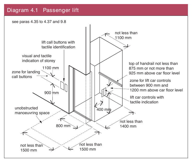
4.36A passenger lift should have a power operated horizontal sliding door or doors which provide a clear width of not less than 800 mm. See Diagram 4.1.
The door or doors to a passenger lift should be fitted with –
(a)an adjustable door timing device; and
(b)a door reactivating device, which prevents physical contact between the user and the leading edge of the closing door or doors.
Lift door or doors should be distinguishable, through suitable visual contrast, from the adjacent landing, and internal car, wall surfaces.
4.37The controls within the lift car should be located not less than 900 mm, and not more than 1200 mm above the floor of the car, and not less than 400 mm horizontally from any return wall of the lift car. See Diagram 4.1.
4.38Visual indication and voice indication of the lift arrival and its location, should be provided in the lift lobby and within the lift car.
Lifting platforms
#Source page 35
4.39A lifting platform should only be provided to transfer wheelchair users, people with reduced mobility and their companions vertically between levels or storeys.
All users, including wheelchair users, should be able to reach and use the controls that summon and direct the lifting platform.
People using a lifting platform need audible and visual information to tell them that the platform has arrived, and which floor it has reached.
4.40A lifting platform should be contained within a liftway enclosure where –
(a)the vertical travel distance is more than 2000 mm; or
(b)the lifting platform travels through a floor penetration.
4.41A lifting platform should have a platform size of –
(a)not less than 800 mm wide and not less than 1250 mm deep, where the lifting platform is not contained within a liftway enclosure;
(b)not less than 900 mm wide and not less than 1400 mm deep, where the lifting platform is contained within a liftway enclosure;
(c)not less than 1100 mm wide and not less than 1400 mm deep, where there are two lift doors located at 90o relative to each other; or
(d)not less than 1100 mm wide and not less than 1400 mm deep, where the lifting platform is designed and constructed to accommodate an accompanied wheelchair user.
4.42A lifting platform should have a door or doors which provide an effective clear width of not less than –
(a)900 mm, where the size of the lifting platform is not less than 1100 mm wide and not less than 1400 mm deep; or
(b)800 mm in any other case.
A door or doors to a lifting platform should be distinguishable, through suitable visual contrast, from that of the adjacent wall surfaces.
4.43The platform controls for a lifting platform should be –
(a)of the continuous pressure type; and
(b)positioned not less than 800 mm and not more than 1100 mm above the floor of the lifting platform and not less than 400 mm horizontally from the front face of the lifting platform.
4.44Visual indication and audible indication of the lifting platform arrival and the floor reached, should be provided within the lifting platform.
4.45Clear permanent operating instructions should be provided either in, or adjacent to, the lifting platform.
General
#Source page 36
Section 5 Facilities in buildings other than dwellings
General
5.1This Section gives guidance to ensure that people have access to facilities that are provided in a building. Provisions for sanitary accommodation and associated sanitary facilities are given in Section 6.
Reception
5.2As the area inside the entrance (or associated lobby) is the first point of contact with a building’s activities and resources, consequently, the reception area in particular should be easily identifiable and also convenient to use.
Fixed reception counter
5.3Where a fixed reception counter is provided in a space immediately inside the principal entrance, accessible entrance or associated lobby, it should –
(a)be readily apparent from the entrance doors or entrance lobby;
(b)be located so as not to be subject to the risk of extraneous external noise; and
(c)have a means of access that complies with paragraphs 4.4 to 4.9.
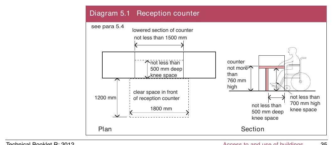
5.4At least one section of a reception counter should have –
(a)its working surface not more than 760 mm above floor level for a length of not less than 1500 mm;
(b)a knee space of not less than 500 mm deep by not less than 700 mm above floor level; and
(c)a clear space 1200 mm deep by 1800 mm wide in front of the lower section of the reception counter.
This section of the reception counter should be located in an obvious position.
See Diagram 5.1.
Diagram 5.1 Reception counter
Audience seating
#Source page 37
5.5Where permanent or removable seating is provided as part of the design, allowance should be made for people who have a disability to have a choice of seating location at spectator events. Wheelchair users and those with a mobility impairment should be provided with spaces into which they can manoeuvre easily, and which offer them a clear view of the activity taking place, while ensuring they are not segregated into special areas and not obstructing the view of other users.
Wheelchair users and people who have difficulty in using seats with fixed arms should have the choice of sitting next to a companion wheelchair user or a conventionally seated person.
5.6Where there is fixed audience seating, wheelchair spaces should be provided in accordance with Table 5.1.
| Table 5.1 Provision of wheelchair spaces in audience seating | |
|---|---|
| Seating capacity | Minimum provision of wheelchair spaces |
| up to 600 | 1% of total seating capacity (or part thereof) to be permanent wheelchair spaces augmented by the provision of removable seating to create, in total, 6 wheelchair spaces |
| 601 to 10,000 | 1% of total seating capacity (or part thereof) to be permanent wheelchair spaces |
| 10,001 to 20,000 | 100, plus 5 per 1000 (or part thereof) above 10,000 (all to be permanent wheelchair spaces) |
| 20,001 to 40,000 | 150, plus 3 per 1000 (or part thereof) above 20,000 (all to be permanent wheelchair spaces) |
| more than 40,000 | 210, plus 2 per 1000 (or part thereof) above 40,000 (all to be permanent wheelchair spaces) |
| Example 1: A facility has an audience seating capacity of 2,350 therefore 1% of 2350 = 23.5 rounded up to 24 wheelchair spaces. Example 2: A facility has an audience seating capacity of 28,500 therefore 150 spaces are required for the first 20,000, the remaining 8,500 is rounded up to 9,000 which requires 27 spaces (3 per 1000). Therefore 177 wheelchair spaces must be provided. |
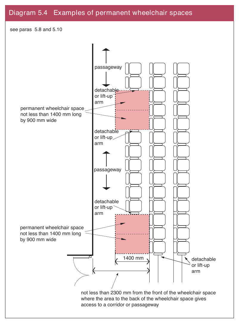
5.7A wheelchair space should –
(a)have a horizontal floor area; and
(b)be not less than 900 mm wide by 1400 mm deep.
5.8Wheelchair spaces should be located –
(a)in a range of single and double wheelchair spaces, with a standard seat to at least one side of each space or group of spaces; and
(b)in such a way as to give a range of views.
See Diagrams 5.2, 5.3 and 5.4.
5.9Any stepped gangway to stepped terrace audience seating, should have a suitable means of providing support to people who have physical difficulty in negotiating changes of level.
Page 38
#Source page 38
Diagram 5.2 Typical arrangement of wheelchair spaces
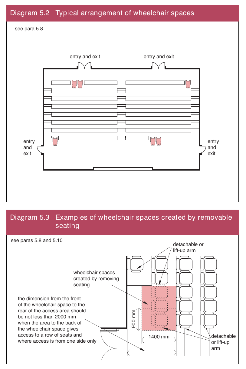
5.10Standard fixed seating at the ends of rows and those adjacent to wheelchair spaces should, where they have arm rests, have detachable or liftup arm rests. See Diagrams 5.3 and 5.4.
Page 39
#Source page 39
Diagram 5.4 Examples of permanent wheelchair spaces
Refreshment facilities
#Source page 40
5.11Refreshment facilities, such as restaurants and bars, should be designed so that they can be accessed and used by all people. All floor areas in a refreshment facility, even when located at different levels, should be accessible, see paragraph 4.3.
Bars and counters (or sections of them) should be at a level suitable for wheelchair users. However, consideration should be given to the specific use of the bar or counter and the interaction of the users with it.
5.12In a refreshment facility e.g. a restaurant or a bar, people should have access to and use of –
(a)the full range of services offered; and
(b)bar and selfservice counters.
5.13A serving counter or bar counter should have not less than one section of its working surface at a height of 850 mm above floor level for a length of not less than 1500 mm.
5.14A level threshold complying with the provisions of paragraph 3.10, should be provided to any doorway between the refreshment facility in a building and any associated external seating area.
Shared refreshment facilities
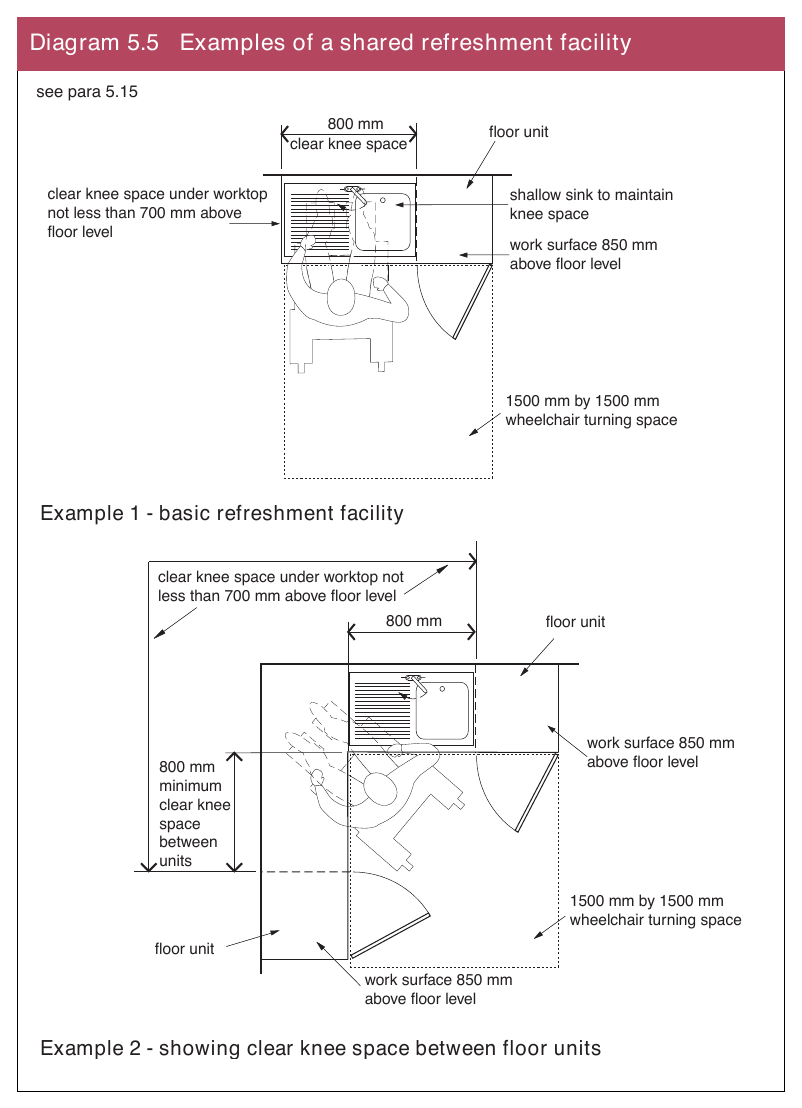
5.15A shared selfcatering refreshment facility e.g. a facility for tea making, should have –
(a)a work surface at 850 mm above floor level; and
(b)a clear knee space below the work surface –
(i)of not less than 700 mm above floor level; and
(ii)where appropriate, not less than 800 mm between floor units. See Diagram 5.5.
Page 41
#Source page 41
Diagram 5.5 Examples of a shared refreshment facility
Guest bedrooms
#Source page 42
5.16Sleeping accommodation, where provided for a significant number of people, e.g. in hotels, motels, purpose built student living accommodation, etc., should be convenient for all.
All guest bedrooms
5.17All guest bedrooms should include facilities that make them suitable for people who do not use a wheelchair, but may have mobility, sensory, dexterity or learning difficulties.
It is important to ensure that, in all bedrooms, builtin wardrobes and shelving are accessible and convenient to use.
5.18Where door signage is provided to a guest bedroom, it should have suitable tactile indication of the room name or number.
5.19Where an opening window is provided to a guest bedroom –
(a)the opening portion should be not less than 800 mm above floor level; and
(b)a control used for opening or closing a window should be –
(i)located not less than 800 mm and not more than 1000 mm above floor level; and
(ii)designed and constructed for single handed use.
5.20Where a fixed storage system has swing doors, these doors should be capable of opening through 180º.
5.21Door furniture to fixed storage systems, within guest bedrooms, should be –
(a)easy to grip and operate; and
(b)distinguishable, through suitable visual contrast, from the face of the door leaf.
5.22All guest bedrooms should have a visual fire alarm signal in addition to the requirements of Part E.
Wheelchair accessible guest bedrooms
5.23As people who use wheelchairs require greater provision of space, a proportion of the guest bedrooms should be designed for independent use by wheelchair users.
Wheelchair accessible bedrooms should be no less advantageously situated than other bedrooms.
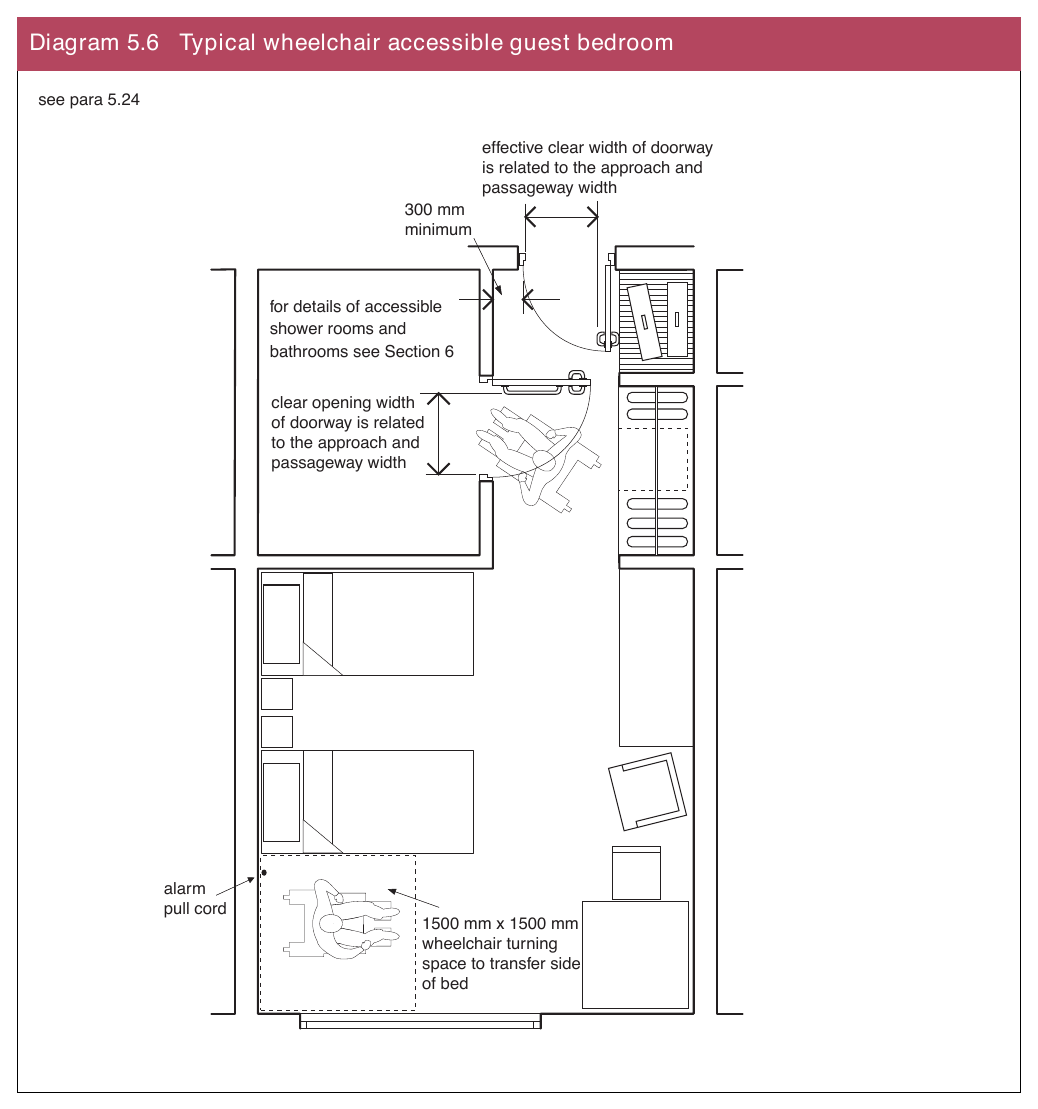
5.24At least one guest bedroom out of every 20 (or part thereof) guest bedrooms should be wheelchair accessible.
Where there is more than one wheelchair accessible bedroom provided, they should be positioned within the building to give a range of locations.
A typical wheelchair accessible guest bedroom is shown in Diagram 5.6.
Page 43
#Source page 43
Diagram 5.6 Typical wheelchair accessible guest bedroom
Page 44
#Source page 44
5.25Where a wheelchair accessible guest bedroom has a balcony, there should be access to it by a doorway –
(a)that has a clear opening width that complies with Table 4.1;
(b)with a level threshold that complies with the provisions of paragraph 3.10; and
(c)with a clear space to the bedroom side of not less than 1500 mm deep.
Where a door to a balcony contains glazing, it should have a zone of visibility from a height above floor level of not more than 900 mm to not less than 1200 mm.
5.26Where a door viewer is provided to the entrance door to a wheelchair accessible guest bedroom a second door viewer should also be provided. These door viewers should be positioned at 1050 mm and 1500 mm above floor level.
5.27A wheelchair accessible guest bedroom should have an emergency assistance alarm –
(a)that is activated by a pull cord, complying with the provisions of paragraph 5.46, that can be operated from the bed and from the adjacent floor area at the transfer side of the bed;
(b)with a reset button, that can be operated from the bed and from the adjacent area at the transfer side of the bed;
(c)having a visual and an audible indication that the emergency alarm has been activated; and
(d)having a visual and an audible call signal positioned immediately outside the wheelchair accessible bedroom and at a central monitoring point.
Wheelchair accessible changing facilities
#Source page 45
5.28In buildings where changing facilities are provided, some disabled people may require the privacy and convenience of an individual selfcontained cubicle or compartment. The selfcontained cubicle or compartment should allow space for an assistant.
Provision of manoeuvring space for a wheelchair, to enable turning and transfer onto the seat, and provision of mirrors and clothes hooks mounted at suitable heights, are all critical features in relation to independent or assisted use of changing facilities. It is important that the seat and grab rails have suitable structural fixing support.
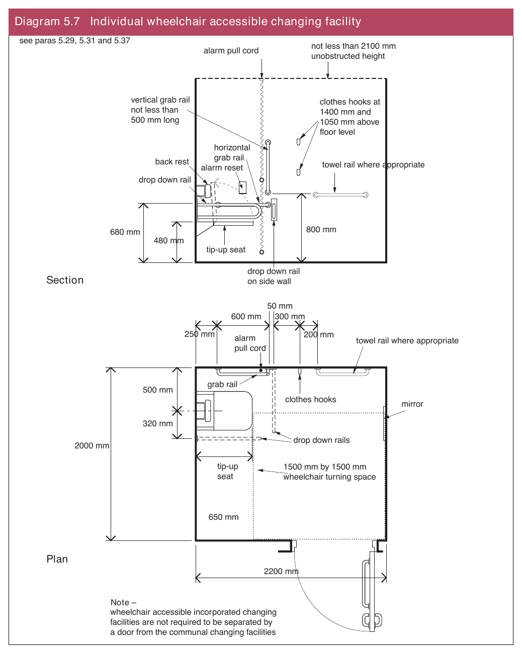
5.29A communal changing facility should have not less than one wheelchair accessible incorporated changing facility. An incorporated changing facility should have the minimum dimensions and arrangement of fittings as shown in Diagram 5.7. A wheelchair accessible incorporated changing facility is not required to be separated by a door from the communal changing facility.
5.30A building for sports facilities should have an individual wheelchair accessible changing room. This is in addition to the provisions of paragraph 5.29.
5.31Where changing facilities are provided for general use and are not associated with showering facilities (e.g. in a clothes shop), not less than one individual wheelchair accessible changing room should be provided. See Diagram 5.7.
5.32Where there is more than one individual wheelchair accessible changing facility, a mixture of left and right hand transfer layouts should be provided to give the user a choice of transfer sides.
5.33Every individual and incorporated wheelchair accessible changing facility should have –
(a)an emergency assistance alarm complying with the provisions of paragraph 6.5; and
(b)an emergency assistance alarm pull cord complying with the provisions of paragraph 5.46, that can be reached from the tipup seat and the area adjacent to the seat.
5.34A wheelchair accessible changing facility should have a clear space not less than 1500 mm deep in front of any fixed clothing storage system.
5.35Where a door is provided to a wheelchair accessible changing facility, it should be capable of being opened outwards, from the outside, in the case of an emergency.
5.36Where a fire alarm is provided within a wheelchair accessible changing facility, it should emit both an audible and visual alarm signal.
5.37A wheelchair accessible changing facility should, where it is associated with a shower facility, have –
(a)a floor with a surface that reduces the risk of slipping; and
(b)a fixed storage system for limb storage, for the benefit of amputees.
An individual wheelchair accessible changing facility is shown in Diagram 5.7.
Page 46
#Source page 46
Diagram 5.7 Individual wheelchair accessible changing facility
Outlets, switches and controls
#Source page 47
5.38The key factors that affect the use of outlets, switches, and controls are ease of operation, visibility, height and freedom from obstruction. However, there can be exceptions to height requirements for some outlets, e.g. those set into the floor.
Outlets, switches and controls that contrast visually with their surroundings are more convenient for visually impaired people.
The location of socket outlets in relation to doorways and return walls should, where practicable, be consistent throughout the building to further reinforce the ease with which people manipulate switches and controls.
Light switches that are activated by a large push pad are also more convenient for visually impaired people to use.
All people who would reasonably expect to use a control should be able to locate it, know which setting it is on and use it without inadvertently changing its setting.
5.39Paragraphs 5.36 and 5.41 to 5.44 should not apply where the outlet, switch or control is required only for maintenance purposes or not intended for operation by the users of the building.
An outlet, switch or control should not require the simultaneous use of two hands unless this mode of operation is required for reasons of safety.
5.40An outlet, switch or control face plate should be distinguishable, through suitable visual contrast, from the background against which it is seen.
Outlets
5.41An outlet for a nonpermanently wired appliance e.g. socket outlet, telephone outlet, etc., should be located within horizontal reach and not less than 400 mm and not more than 1000 mm above the floor level. See Diagram 5.8(a)(1). However, the provisions of this paragraph should not apply to any outlet that is set into a flush mounted floor box located within areas that are designed to be open plan.
5.42Socket outlets should be located not less than 350 mm from any return wall.
Switches and controls
5.43A switched outlet should clearly indicate when in the “on” position (e.g. by a neon indicator, or the top of the rocker is coloured red and exposed when in the “on” position etc.).
5.44A switch or control –
(a)should be located within horizontal reach;
(b)for a permanently wired appliance, should be located not less than 400 mm and not more than 1200 mm above floor level. See Diagram 5.8(a)(2). However, where the design of the appliance requires the switch to be placed at a higher level then it should be not more than 1400 mm above floor level;
Page 48
#Source page 48
(c)for artificial lighting, should be located not less than 900 mm and not more than 1100 mm above floor level. See Diagram 5.8(a)(3). Where the switch is installed for the use of visitors or customers it should be of the large push pad type;
(d)that requires precise hand movement (e.g. a ventilation controller), should be located not less than 750 mm and not more than 1200 mm above floor level. See Diagram 5.8(a)(4);
(e)that is operated using push buttons that require limited dexterity (e.g. door bell, entry phone, etc.), should be located not more than 1200 mm above floor level. See Diagram 5.8(a)(5);
(f)that requires the user to read a display or setting (e.g. a thermostat), should be located not less than 1200 mm and not more than 1400 mm above floor level. See Diagram 5.8(a)(6); and
(g)for a power operated door, should be located not less than 750 mm and not more than 1000 mm above floor level. See Diagram 5.8(b).
5.45A light cord pull switch should have a 50 mm diameter bangle attached at a height of not less than 900 mm and not more than 1100 mm above floor level. See Diagram 5.8(a)(3). The bangle should be distinguishable through suitable visual contrast, from the background against which it is seen.
Where a pull cord light switch is installed in a room or space that also contains an emergency assistance alarm both the pull cord and the bangle should be distinguishable visually from any emergency assistance alarm pull cord.
5.46An emergency assistance alarm should have a red coloured pull cord with two red coloured 50 mm diameter bangles. The lower bangle should be set at a height of 100 mm above floor level and the upper bangle should be located not less than 800 mm and not more than 1000 mm above floor level. See Diagram 5.8(a)(7).
Page 49
#Source page 49
Diagram 5.8 Outlets, switches and controls
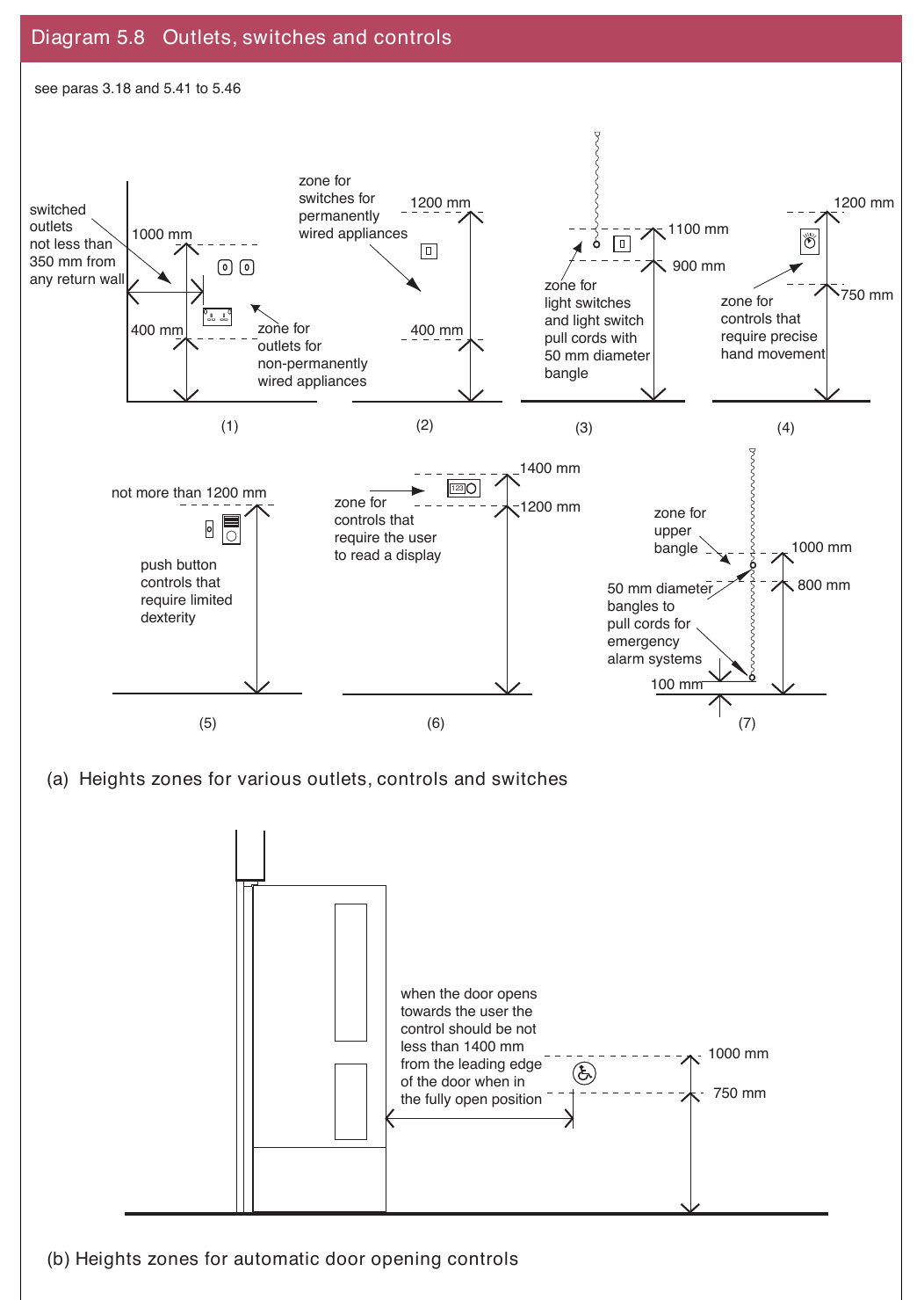
Aids to communication
#Source page 50
5.47In order to obtain the full benefit of attending public performances or taking part in meetings/lectures, a person using an electronic hearing device needs to receive a signal that is amplified in both volume and signal to noise ratio. The three systems commonly used to provide this enhanced level of sound are induction loop, infrared and radio. Sound field systems are also increasingly being used, particularly in educational establishments. It should be recognised that where adjacent spaces each have an induction loop system there is potential for the signals to overlap.
5.48A suitable hearing enhancement system should be provided in –
(a)auditoria and rooms or spaces for performance or spectating;
(b)meeting rooms and lecture rooms which are more than 60 m² in area; and
(c)any service or reception area –
(i)where the visitor or customer is separated from the vendor by a glazed screen; or
(ii)that is subject to the risk of excessive extraneous noise.
5.49A hearing enhancement system, provided to comply with the provisions of paragraph 5.48, should be readily apparent to those who require to use it
(e.g. indicated by the standard symbol).
5.50A hearing enhancement system should not be subject to extraneous electrical interference from any artificial lighting installation.
General
#Source page 51
Section 6 Sanitary accommodation and associated sanitary facilities in buildings other than dwellings
General
6.1A number of issues need to be considered in connection with all forms of sanitary accommodation and associated sanitary facilities. These relate to the needs of people with sensory impairments, people with learning difficulties and people whose lack of tactile sensitivity can cause them to be injured by touching hot surfaces.
Controls and water closet cubicle doors should be operable by people with limited strength or limited manual dexterity and doors to cubicles should be capable of being opened if a person has collapsed against them while inside the cubicle. Preferably, all doors to water closet cubicles and wheelchair accessible unisex toilets should open out or, if they open in, the door swing should not encroach into the wheelchair turning space or activity space.
6.2A bath, basin or shower terminal fitting in an educational building, or within a facility provided for the use of the public, should –
(a)be supplied with water, through a device or other suitable means, so that the temperature of the water discharged at the outlet does not exceed 43ºC; and
(b)have the flow of water controlled, either automatically or by a device, that is capable of being operated with a closed fist (e.g. by a lever action).
6.3A door to a water closet compartment or unisex accessible sanitary accommodation should –
(a)comply with the provisions of paragraph 3.13 and 3.15;
(b)where a privacy bolt is installed, be fitted with a privacy bolt that can be operated by people with limited dexterity; and
(c)be capable of being opened outwards from the outside in the case of an emergency.
6.4An emergency assistance alarm should be provided in –
(a)wheelchair accessible sanitary accommodation;
(b)a wheelchair accessible shower room; and
(c)a wheelchair accessible bathroom.
6.5An emergency assistance alarm provided in those locations referenced in paragraph 6.4 should have –
(a)a signal distinguishable from that of any installed fire alarm;
(b)a visual and an audible indication to confirm to the user that the emergency alarm has been activated; and
Sanitary accommodation
#Source page 52
(c)a visual and an audible call signal outside the wheelchair accessible facility. This should be located in an area where it will be easily seen and heard by those who may be able to give assistance.
6.6An emergency assistance alarm activating pull cord should –
(a)comply with the provisions of paragraph 5.46;
(b)where it is within unisex accessible sanitary accommodation, be reachable from the water closet and the floor of the transfer space adjacent to the water closet;
(c)where it is within a wheelchair accessible shower facility, be reachable from the shower seat and the transfer space adjacent to the shower seat; and
(d)where it is within a wheelchair accessible bath facility, be reachable from the bath and the transfer space adjacent to the bath.
6.7An emergency assistance alarm reset button(s) should be capable of being operated from the –
(a)water closet, within wheelchair accessible sanitary accommodation;
(b)shower seat, within a wheelchair accessible shower room; and
(c)bath, within a wheelchair accessible bathroom.
6.8A heat emitter within sanitary accommodation, with which a person is likely to come into contact, that has any exposed surface capable of being heated to a temperature of 43ºC or more, should be adequately guarded.
6.9Sanitary fittings (e.g. water closet, urinal, etc.) grab rails and support rails within a water closet compartment or unisex wheelchair accessible sanitary accommodation, should be distinguishable, through suitable visual contrast, from the background against which they are seen.
6.10Sanitary accommodation is somewhere people are likely to be in relative isolation. In a building where a fire alarm is provided to comply with Part E any sanitary accommodation should have a visual fire alarm signal in addition to the requirements of Part E.
Sanitary accommodation
6.11Sanitary accommodation needs to be suitable for all people who use the building. For people with a disability, suitable toilet accommodation may take the form of a specially designed cubicle in separate sex toilet washrooms or a self contained unisex toilet. For wheelchair users in particular, a self contained unisex toilet is always the preferred option since, if necessary, a partner or carer of a different sex can give assistance. Even if wheelchair accessible accommodation is provided in separate sex toilet washrooms wheelchair accessible unisex toilets should also be provided.
The provision of an enlarged cubicle in a separate sex toilet washroom can benefit ambulant people who have a disability, people with assistance dogs, as well as people with children and people (e.g. those with luggage) who need an enlarged space.
Page 53
#Source page 53
Wheelchair users should be able to gain access to and conveniently use sanitary accommodation. Ensuite sanitary facilities are the preferred option for wheelchair accessible bedrooms. Unless there are compelling reasons for not doing so, there should be at least as many ensuite shower rooms as ensuite bathrooms, as some people may find it easier to use a shower than a bath.
6.12At each location where there is sanitary accommodation for visitors, customers or staff, at least one unit of unisex wheelchair accessible sanitary accommodation should be provided. See Diagram 6.1. However, where the space within a building is severely restricted and only one unit of sanitary accommodation is provided for use by all persons, that sanitary accommodation may be as shown in Diagram 6.2.
6.13Within traditional separate sex sanitary accommodation, not less than one compartment suitable for people who are ambulant disabled should be provided. See Diagram 6.3(a).
6.14Where the separate sex sanitary accommodation contains 4 or more water closet compartments, not less than one compartment should be enlarged as shown in Diagram 6.3(b).
6.15The sanitary accommodation for a guest bedroom which is designed as a wheelchair accessible bedroom, should be provided either –
(a)ensuite, where that is the arrangement for the rest of the bedrooms; or
(b)nearby and on the same storey as the wheelchair accessible bedrooms, with at least one unit for every 6 such bedrooms or part thereof.
This provision is in addition to that required by paragraph 6.12.
Page 54
#Source page 54
Diagram 6.1 Wheelchair accessible unisex sanitary accommodation
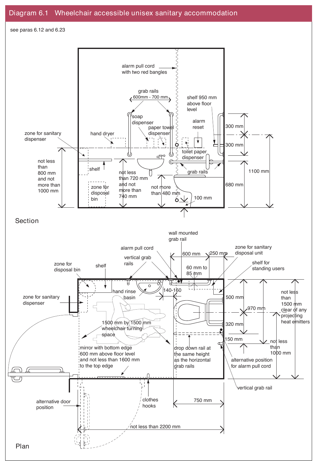
Page 55
#Source page 55
Diagram 6.2 Wheelchair accessible unisex sanitary accommodation incorporating a
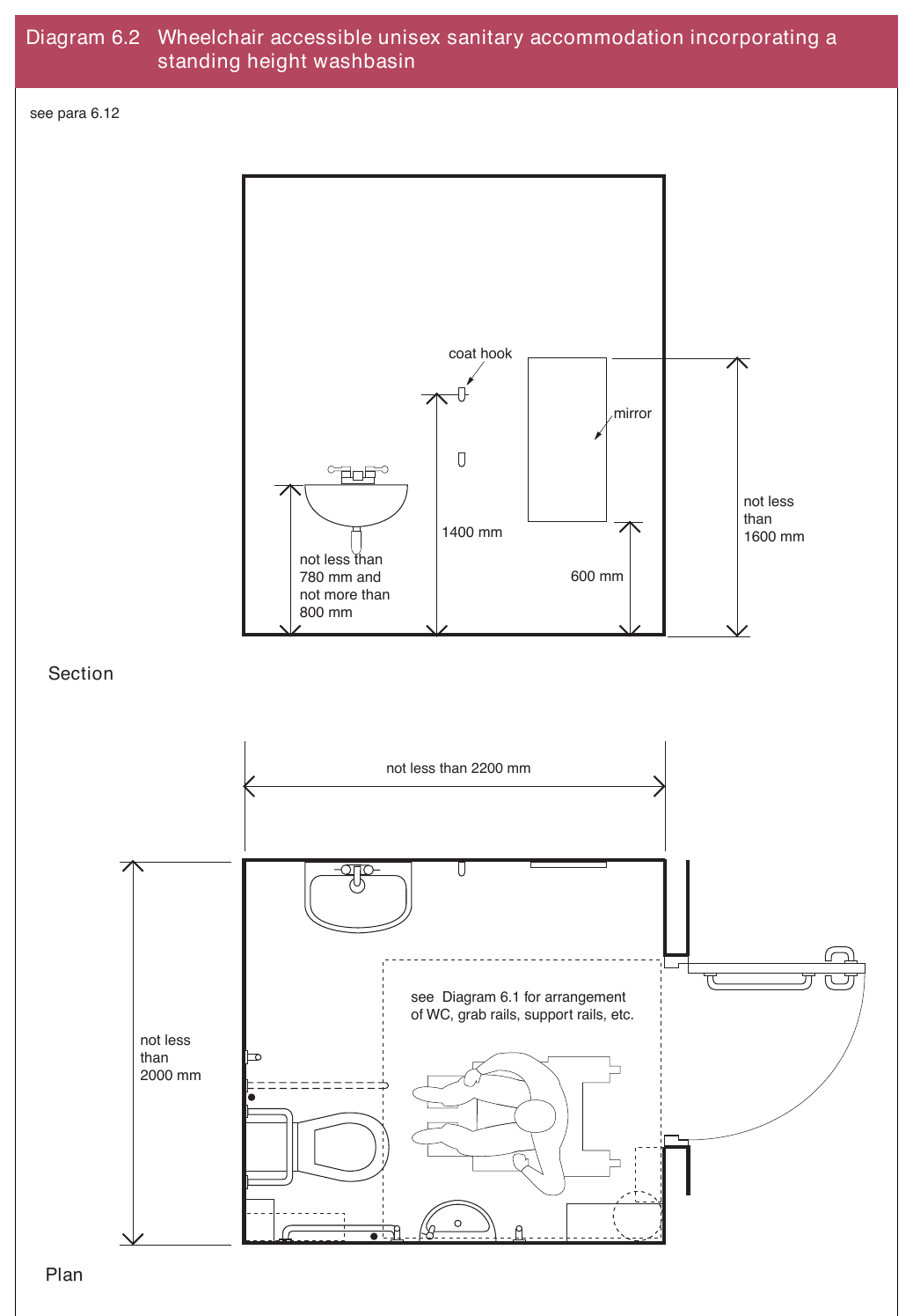
Page 56
#Source page 56
Diagram 6.3 Water closet compartments
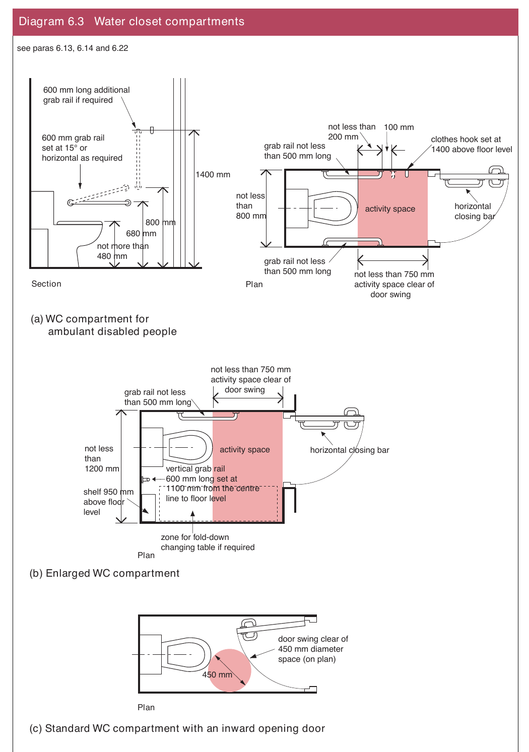
Wheelchair accessible unisex sanitary accommodation
#Source page 57
6.16Wheelchair users should be able to approach, transfer to and use the sanitary facilities provided within a building. This requires the provision of a wheelchair accessible unisex toilet. The relationship of the water closet to the hand rinse basin and other accessories should allow a person to wash and dry hands while seated on the water closet before transfering back to the wheelchair. The space provided for manoeuvring should enable wheelchair users to adopt various transfer techniques that allow independent or assisted use. It is important that the transfer space alongside the water closet is kept clear to the back wall. When transferring to and from their wheelchair, some people need horizontal support rails.
The time needed to reach a wheelchair accessible toilet should be kept to a minimum when considering the location of unisex toilet accommodation.
Some wheelchair users find it difficult to use a standard height water closet seat and, for them, it is important that the water closet pan can accept a variable height toilet seat riser.
6.17Where there is more than one unit of unisex wheelchair accessible sanitary accommodation –
(a)within a building of two or more storeys, the unisex accommodation should be located in a similar position on each floor, where the sanitary accommodation is provided, and should allow for right and left hand transfers on alternate floors; or
(b)within a single storey building, there should be a mixture of left and right hand transfer layouts.
6.18Unisex wheelchair accessible sanitary accommodation should have –
(a)a horizontal closing bar, fixed to the inside face of the door;
(b)a water closet, complying with the key dimensions shown in Diagram 6.4; and
(c)the cistern flushing lever, located on the transfer space side of the water closet.
6.19Where a heat emitter is provided within unisex wheelchair accessible sanitary accommodation, it should be located so as not to cause an obstruction within the wheelchair manoeuvring space or the transfer space adjacent to the water closet.
6.20The horizontal travel distance from any area, to which a wheelchair user has access, to unisex wheelchair accessible sanitary accommodation should –
(a)be not more than 40 m on the same storey; and
(b)be not more than 40 m cumulative horizontal travel distance, where the unisex wheelchair accessible sanitary accommodation is on any other storey, and is accessed by a passenger lift. However, where the unisex sanitary accommodation is on a storey accessed by a lifting platform, the vertical travel should be not more than one storey.
Traditional separate sex sanitary accommodation
#Source page 58
Diagram 6.4 Key dimensions of a water closet pan
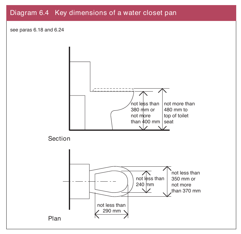
Traditional separate sex sanitary accommodation
6.21Those who are ambulant disabled people should have the opportunity to use a water closet compartment within any separate sex toilet washroom. The compartment should be fitted with support rails, and include a minimum activity space to accommodate people who use crutches, or otherwise have impaired leg movements. The presence of this facility helps avoid unnecessary travel to unisex toilet accommodation.
Some ambulant disabled people find it difficult to use a standard height water closet seat and, for them, it is important that the water closet pan is of a suitable size to accommodate a personal variable height toilet seat riser.
Where the separate sex sanitary accommodation is accessible by wheelchair users, those users would benefit by having a washbasin and where appropriate, a urinal, installed at a height lower than that provided for other users. Within this sanitary accommodation, it is not necessary for the water closet compartments to be accessible for wheelchair users to benefit from these lower fittings.
6.22Within traditional separate sex sanitary accommodation, a water closet compartment not designed as suitable for ambulant disabled people or wheelchair users should, where the door opens into the compartment, have an unobstructed manoeuvring space of not less than 450 mm diameter clear of any door swing. See Diagram 6.3(c).
Shower and bath facilities
#Source page 59
6.23Where a wheelchair accessible water closet compartment is provided within traditional separate sex sanitary accommodation, it should have the minimum dimensions and arrangement of fittings as shown in Diagram 6.1.
6.24A compartment suitable for disabled people who are ambulant should have a water closet complying with the key dimensions shown in Diagram 6.4.
6.25Where separate sex sanitary accommodation is accessible by wheelchair users –
(a)at least one washbasin should have –
(i)its rim not less than 720 mm and not more than 740 mm above floor level; and
(ii)two vertical grab rails located as shown in Diagram 6.5(a), and
(b)where urinals are installed, at least one urinal should have –
(i)its rim at 380 mm above floor level; and
(ii)two vertical grab rails located as shown in Diagram 6.5(b).
Diagram 6.5 Heights of various fittings in wheelchair accessible
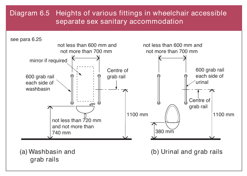
Shower and bath facilities
6.26Wheelchair users and disabled people who are ambulant should be able to wash, shower or bathe either independently or with assistance. The relationship of the shower or bath to other sanitary fittings, and to the space required for manoeuvring, is therefore critical.
In buildings where communal shower facilities are provided, many people with a disability will use changing areas that are open to the communal area, whereas some will require the privacy and convenience of an individual selfcontained cubicle or compartment.
Providing a choice of shower room or bathroom layout, wherever possible, will meet the needs of many people who have a disability and help maintain their independence and dignity.
Shower facilities
#Source page 60
A choice of shower layout combined with the correct location of shower controls and fittings will allow people who are disabled to use the facilities independently or to be assisted by others if required.
The guidance given in paragraph 6.34 applies to wheelchair accessible bathing facilities where provided in buildings such as hotels, motels, sports facilities, etc. where baths are provided as an alternative, or as a supplement, to showers.
6.27Where a communal shower facility is provided, it should include a wheelchair accessible incorporated shower facility within it. Incorporated shower facilities should have the minimum dimensions and arrangement of fittings as shown in Diagram 6.6.
6.28In addition to the requirements of paragraph 6.27, where there is a shower facility in a building for sports activities, an individual wheelchair accessible shower room should also be provided. See Diagram 6.6.
6.29Where there is a shower facility for staff, not less than one individual wheelchair accessible shower room should also be provided. However, where it is impracticable to provide an individual wheelchair accessible shower room, an incorporated individual wheelchair accessible shower facility should be provided.
6.30A wheelchair accessible bedroom should have a shower or bath facility complying with the provisions of paragraphs 6.33 and 6.34 provided either –
(a)ensuite, where that is the arrangement for the rest of the bedrooms; or
(b)nearby, and on the same storey as the wheelchair accessible bedrooms and with at least one shower or bath facility for every 6 such bedrooms or part thereof.
6.31Where there is more than one wheelchair accessible shower or bath facility, a mixture of left and right hand transfer layouts should be provided to give the user a choice of transfer sides.
6.32An individual wheelchair accessible shower or bath facility should have a fixed storage system for limb storage for the benefit of amputees.
Shower facilities
6.33An individual wheelchair accessible shower room should have –
(a)the minimum dimensions and arrangement of fittings as shown in Diagram 6.6;
(b)a storage shelf that is reachable from the shower seat or from the wheelchair transfer space;
(c)a floor –
(i)with a surface that reduces the risk of slipping; and
(ii)with a fall not steeper than 1 in 50 towards the floor drain; and
(d)where it incorporates a water closet, the minimum dimensions and arrangement of fittings as shown in Diagram 6.7.
Page 61
#Source page 61
Diagram 6.6 Suitable individual wheelchair accessible shower room
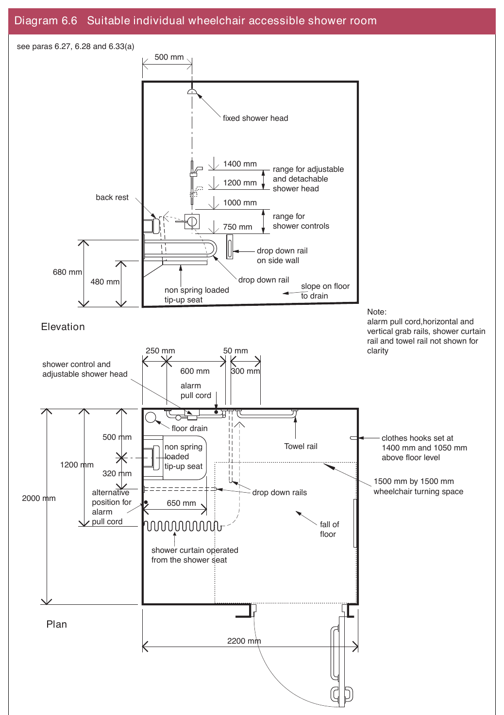
Page 62
#Source page 62
Diagram 6.7 Suitable individual wheelchair accessible shower room incorporating a
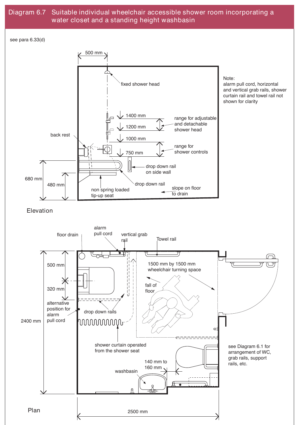
Bath facilities
#Source page 63
6.34An individual wheelchair accessible bathroom should have –
(a)the minimum dimensions and arrangement of fittings as shown in Diagram 6.8;
(b)a floor with a surface that reduces the risk of slipping;
(c)a fixed bath transfer seat, not less than 400 mm deep, having the same width as the bath; and
(d)where it incorporates a water closet, the minimum dimensions and arrangement of fittings as shown in Diagram 6.8.
Page 64
#Source page 64
Diagram 6.8 Suitable bathroom layout incorporating a water closet and a standing height
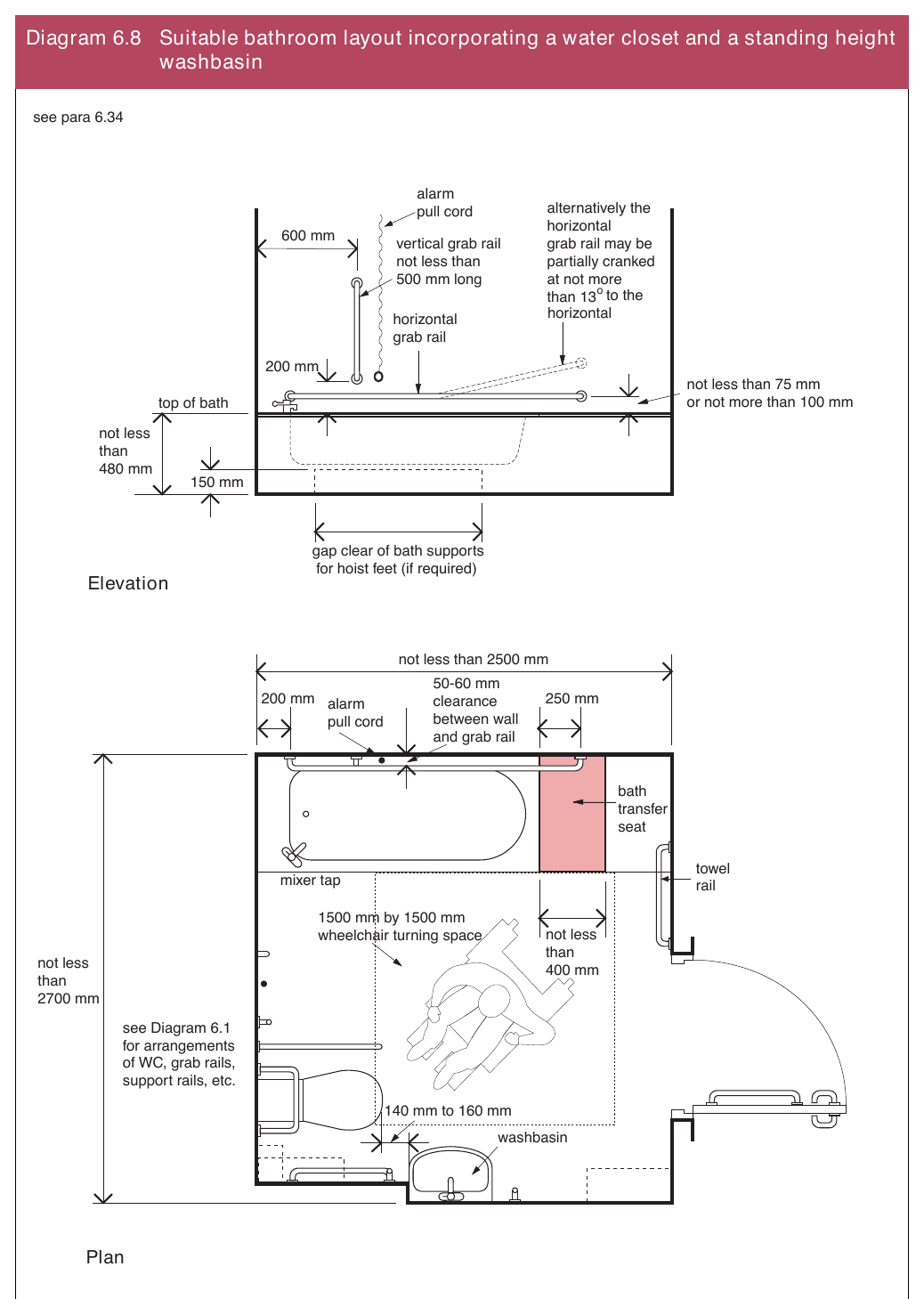
Page 65
#Source page 65
64 Access to and use of buildings Technical Booklet R: 2012
Dwellings and blocks of dwellings
#Source page 66
Access to the dwelling
#Source page 67
Section 7 Means of access to and into a dwelling
Access to the dwelling
7.1A level or ramped approach should be provided to the entrance to a dwelling or to a common entrance to a block of dwellings. However, variations in topography, available plot area, and the distance of the dwelling from the point of access may influence the type of approach that can be provided.
Wheelchair users should be able to have access to the principal entrance. Exceptionally, on steeply sloping plots access may be to a suitable alternative entrance by a level or ramped approach. Where there is no alternative but to provide a stepped approach, the steps should have as few steps as possible as someone using a wheelchair may need assistance to negotiate them.
The presence of a driveway may provide a better opportunity for creating a level or ramped approach, particularly if it also provides the sole means of approach for disabled visitors. The driveway could be designed as the approach to the dwelling or to a common entrance to a block of dwellings. In such cases the approach should exclude the space for any parked vehicle but a vehicle door may open across it.
7.2People with a disability should have access from the point of entry to the principal entrance of a dwelling or the common entrance to a block of dwellings by –
(a)a level approach complying with the provisions of paragraph 7.7; or
(b)a ramped approach.
A combination of (a) and (b) may be used.
7.3Where the plot gradient to the principal entrance of a dwelling or the common entrance to a block of dwellings is greater than –
(a)1 in 15; or
(b)1 in 12 where the travel distance is less than 5 m,
access may be provided to an alternative entrance complying with the provisions of paragraph 7.2.
Where the plot gradient to an alternative entrance is greater than (a) or (b), a stepped approach may be provided.
7.4Where a driveway provides the whole or part of the approach, it should comply with the requrements for a level approach or a ramped approach. The approach should be clear of any parking space.
Where there is a need to guard the approach, guarding to comply with Part H must be provided.
External approach
#Source page 68
7.5The surface of an approach available to a wheelchair user should be firm enough to support the weight of the user and their wheelchair and smooth enough to permit easy manoeuvre. It should also take account of the needs of people using walking aids. Loose laid materials, such as gravel or shingle, are not suitable for an approach.
The width of the approach, excluding space for a parked vehicle, should take account of the needs of a wheelchair user, or a stick or crutch user.
7.6Where the point of entry is at the boundary it should have an unobstructed width of not less than 900 mm.
Level approach
7.7A level approach should have –
(a)a surface which is firm and even;
(b)an unobstructed width not less than 900 mm; and
(c)a slope not steeper than 1 in 20.
Where a level approach has a crossfall it should not exceed 1 in 40.
Access into the dwelling
7.8A level threshold should be provided at the principal entrance or alternative entrance (where the alternative entrance is provided in accordance with paragraph 7.3) even where the approach to that entrance is stepped.
Principal entrance
7.9The principal entrance to a dwelling or the common entrance to a block of dwellings should have a door with a minimum clear opening width of not less than 775 mm and a level threshold. See Diagram 7.1.
The access to the principal entrance to a dwelling or the common entrance to a block of dwellings should be –
(a)level for a distance of not less than 900 mm; and
(b)at or about the level of the floor of the dwelling.
Where access is by an alternative entrance the above provisions should apply to that entrance and not to the principal entrance or the common entrance to a block of dwellings.
Page 69
#Source page 69
Diagram 7.1 Level thresholds
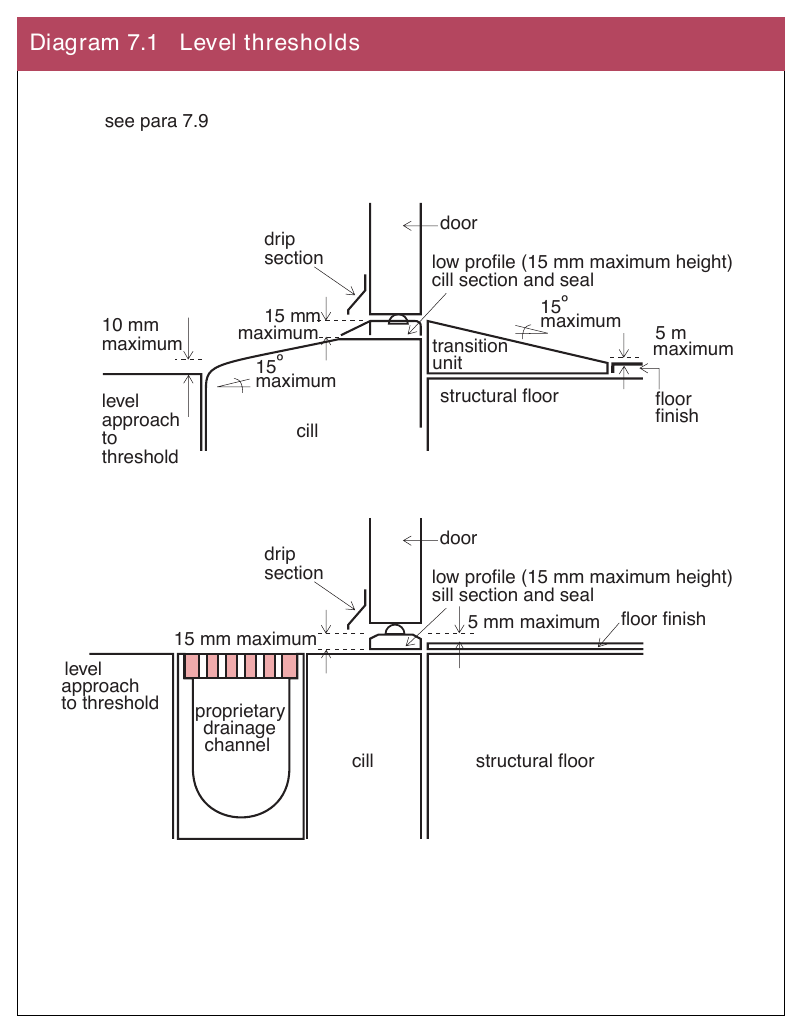
General
#Source page 70
Section 8 Circulation within a dwelling
General
8.1In a dwelling, a person with a disability should have access from the principal entrance (or an alternative entrance) to all habitable rooms and to a sanitary convenience in the entrance storey. However, where there are no habitable rooms in the entrance storey, a person with a disability should have access to all habitable rooms and to a sanitary convenience in the principal storey.
Circulation routes should be sufficiently wide to allow convenient circulation by disabled people. Consideration should be given to the effects of local obstructions such as radiators and other fixtures.
Internal doors should be of a suitable width to facilitate wheelchair manoeuvre and wider doors are needed where a wheelchair cannot approach them head on.
Horizontal circulation
Widths of circulation routes and doorways
8.2The widths of circulation routes and doorways are interrelated and depend on the direction of approach of a wheelchair. Table 8.1 gives the minimum widths of circulation routes for a range of doorway widths and directions of approach.
| Table 8.1 Minimum widths of circulation routes | ||
|---|---|---|
| Clear opening of doorway | Direction of approach | Minimum width of circulation route |
| 750 mm | head on | 900 mm |
| 750 mm | not head on | 1200 mm |
| 775 mm | not head on | 1050 mm |
| 800 mm | not head on | 900 mm |
Vertical circulation
#Source page 71
8.3The width of a circulation route may be reduced to 750 mm at a local permanent obstruction or projection provided that the obstruction or projection is not greater than 2000 mm in length and is not located –
(a)opposite a door to a room; or
(b)where it would prevent a wheelchair user turning into or out of a room.
See Diagram 8.1.
Diagram 8.1 Obstructions in circulation routes
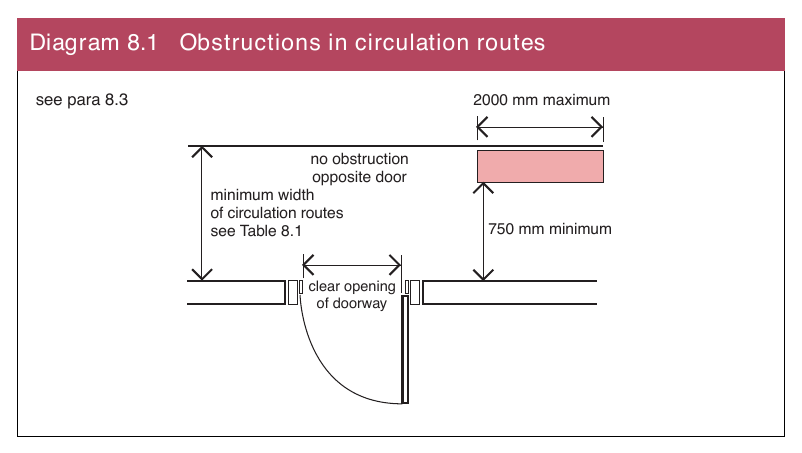
Vertical circulation
8.4Where the circulation route within the entrance storey or the access to the circulation route within the principal storey contains a change of level, a stair may be provided.
General
#Source page 72
Section 9 Circulation within common areas of a block of dwellings
General
9.1Reasonable provision for access should be made from the common entrance of the block of dwellings to the principal entrance of each dwelling so that a person with a disability may visit occupants who live on any storey of a block of dwellings.
9.2This Section deals with access within the common areas of a block of dwellings e.g. flats, and contains provisions for horizontal and vertical circulation.
Common areas are the circulation routes used by the occupants of the dwellings and includes the entrance halls, corridors, lobbies, stairs and lifts.
Horizontal circulation
9.3Circulation routes should be sufficiently wide to allow convenient circulation by people who are disabled. Consideration should be given to the effects of local obstructions such as radiators and other fixtures.
Horizontal circulation routes
9.4A horizontal circulation route within a common area should be level or ramped and have an unobstructed width of not less than 1200 mm.
Where a handrail is provided, the width at handrail level may be reduced to not less than 1000 mm.
Vertical circulation
9.5The most suitable means of access for people who are disabled, to move from one storey to another is a passenger lift. However, a lift may not always be provided.
9.6A vertical circulation route to any storey should be provided by a common stair and where a lift is provided, by a suitable passenger lift.
Passenger lifts
9.7Where a lift is provided, it should be suitable for unassisted use by –
(a)a wheelchair user; and
(b)a person with sensory impairments.
Measures should also be adopted to give people with a disability sufficient time to enter and leave the lift without the risk of contact with the closing doors.
Page 73
#Source page 73
9.8
A passenger lift should –
(a)have a door or doors which provide a clear opening width of not less than 800 mm;
(b)have a car with a width of not less than 900 mm and a depth not less than 1250 mm measured internally;
(c)have controls which are not less than 900 mm or more than 1200 mm above the floor of the car and are not less than 400 mm horizontally from the front wall of the car;
(d)where it serves more than three storeys have visual and audible indications of the floor reached;
(e)incorporate a signalling system which gives 5 seconds notification that the lift is answering a landing call, and a dwell time of 5 seconds before its doors begin to close after they are fully open. The dwell time may be reduced to 3 seconds where the door closing system is overridden by a door reactivating device which relies on photoelectric or infrared methods, but not a door edge pressure system;
(f)have a landing on each storey with –
(i)an unobstructed length and width of not less than 1500 mm in front of the door to the lift; and
(ii)lift call buttons which are not less than 900 mm or more than 1200 mm above the floor level of the landing and are accompanied by suitable tactile indications (on or adjacent to the buttons) to identify the storey and direction of travel; and
(g)have a minimum load capacity of 400 kg.
Many of the above features are shown in Diagram 4.1.
General
#Source page 74
Section 10 Sanitary convenience in a dwelling
General
10.1The objective is to ensure the water closet in the entrance storey or the principal storey of the dwelling is accessible from the habitable rooms in that storey without the need to negotiate a stair to reach it. Where there is a bathroom on that storey, the water closet may be located in that bathroom. It will not always be practical for the wheelchair to be fully accommodated within the water closet compartment.
Access to sanitary conveniences
10.2A water closet should be located so as to have a clear space of not less than 900 mm by 750 mm for a person with a disability to access it (see Diagrams 10.1 and 10.2). The washbasin may project into this clear space provided that it does not impede access to the water closet.
10.3For frontal access to the water closet the clear space should be centred on the water closet as shown in Diagram 10.1.
For oblique access to the water closet the clear space should be offset towards the access as shown in Diagram 10.2.
10.4A doorway providing access to the sanitary convenience should –
(a)be positioned to enable a wheelchair user to access the clear space in front of the water closet;
(b)have a clear opening width of not less than that given in Table 10.1; and
(c)where there is oblique access, be located so that its edge is not in front of, or 250 mm behind, the water closet, unless there is adequate space within the room to manoeuvre a wheelchair.
10.5The door should –
(a)open outwards; or
(b)not impinge at any point of its swing upon the clear space.
| Table 10.1 Clear opening widths of doorways | ||
|---|---|---|
| Minimum width of circulation routes | Direction of approach | Clear opening of doorway |
| 900 mm | head on | 750 mm |
| 1200 mm | not head on | 750 mm |
| 1050 mm | not head on | 775 mm |
| 900 mm | not head on | 800 mm |
Page 75
#Source page 75
Diagram 10.1 Clear space for frontal access to the water closet
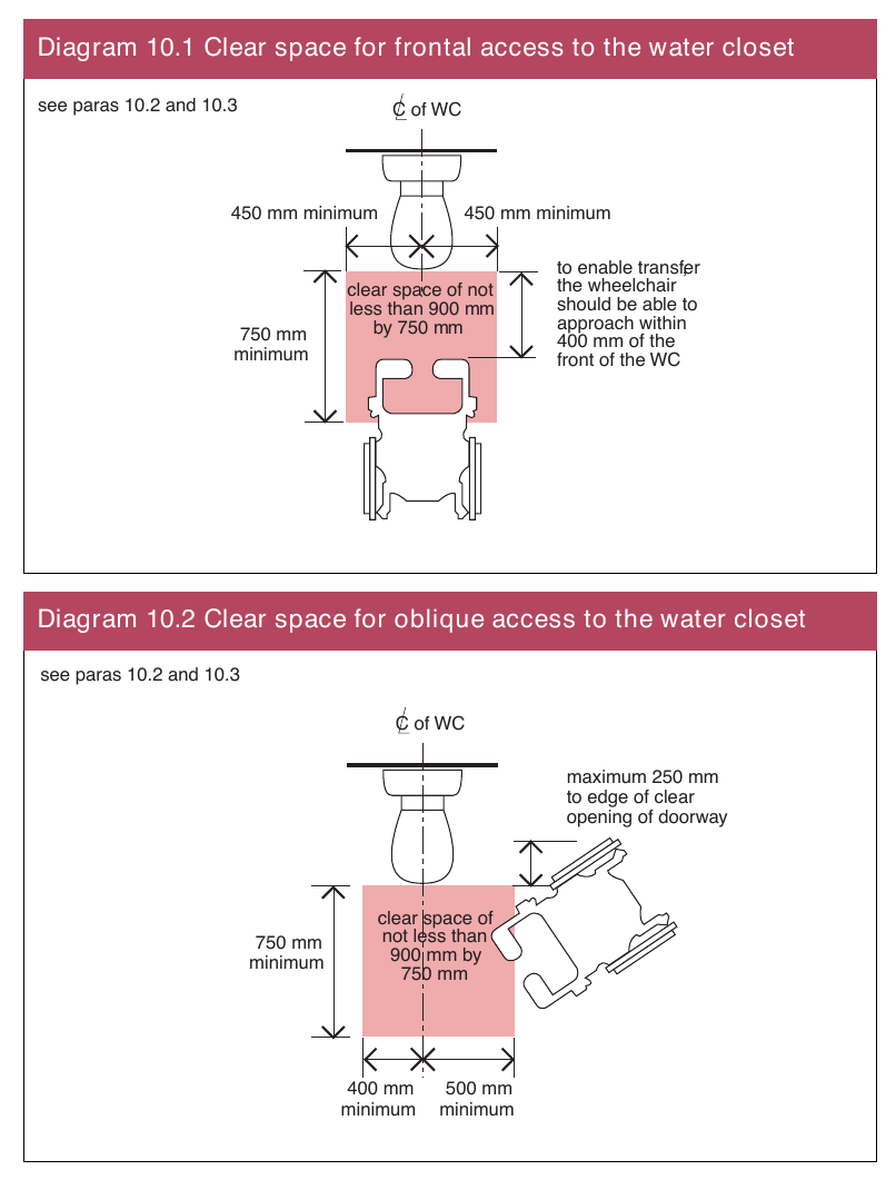
Heights of outlets and switches
#Source page 76
Section 11 Heights of socket outlets, switches, etc. , in a dwelling
Heights of outlets and switches
11.1Wall mounted socket outlets and switches (other than isolators) in the entrance storey, and where appropriate the principal storey, should be located not more than 1200 mm or not less than 450 mm above the floor level. See Diagram 11.1.
11.2The cord of a pull cord switch should terminate not more than 1200 mm above the floor level. See Diagram 11.1.
Diagram 11.1 Heights of switches and socket outlets
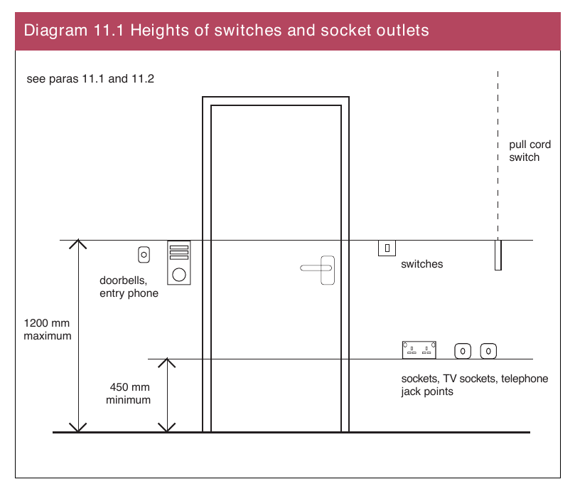
Page 77
#Source page 77
Appendix A Informative – Facilities for people with profound and multiple learning disabilities
The provision of specialist facilities for people with profound and multiple learning disabilities is not a requirement of Building Regulations. However, where it has been decided to provide such a facility, the following information will assist designers in their development decisions for the facility (in relation to location, access, spacial issues, facilities, equipment, etc.).
People with profound and multiple learning disabilities, who require the help of up to two assistants, need a facility that is a combined toilet, shower and changing room.
Such facilities require extra space to accommodate people with, often using large wheelchairs having elevated leg rests, a reclining facility or integral oxygen cylinders, and space to fit slings for use with a hoist. It also needs to be possible for a wheelchair to remain within the facility when not in use without compromising the safe access and use of the equipment.
A Changing Places toilet includes such extra space and facilities.
Where it is decided to include facilities for people with profound and multiple learning disabilities in a building –
(a)specialist advice can be obtained from MENCAP Segal House, 4 Annadale Avenue, Belfast, BT7 3JH (www.mencap.org.uk) or the Changing Places Consortium, (www.changingplaces.org); and
(b)specific guidance on the design of such a facility is given in BS 8300.
It is important to note that a combined toilet, shower and changing room for people with complex and multiple disabilities is not designed for the use of independent wheelchair users and does not negate the need for the provision of unisex wheelchair accessible sanitary accommodation that normally compliments traditional separate sex sanitary accommodation.
DFP Technical Booklet B: 2012 Materials and workmanship
#Source page 78
Appendix B Publications referred to
BS 8300: 2009+A1: 2010 Design of buildings and their approaches to meet the needs of disabled people Code of practice
DFP Technical Booklet B: 2012 Materials and workmanship
Technical Booklets
#Source page 79
The following list comprises the series of Technical Booklets prepared by the Department for the purpose of providing practical guidance with respect to the technical requirements of the Building Regulations (Northern Ireland) 2012.
| Technical Booklet B | Materials and workmanship |
| Technical Booklet C | Preparation of site and resistance to |
| contaminants and moisture | |
| Technical Booklet D | Structure |
| Technical Booklet E | Fire safety |
| Technical Booklet F1 | Conservation of fuel and power in |
| dwellings | |
| Technical Booklet F2 | Conservation of fuel and power in buildings other |
| than dwellings | |
| Technical Booklet G | Resistance to the passage of sound |
| Technical Booklet H | Stairs, ramps, guarding and protection from |
| impact | |
| Technical Booklet J | Solid waste in buildings |
| Technical Booklet K | Ventilation |
| Technical Booklet L | Combustion appliances and fuel storage |
| systems | |
| Technical Booklet N | Drainage |
| Technical Booklet P | Sanitary appliances, unvented hot water storage |
| systems and reducing the risk of scalding | |
| Technical Booklet R | Access to and use of buildings |
| Technical Booklet V | Glazing |
Any person who intends to demonstrate compliance with the Building Regulations by following the guidance given in a Technical Booklet is advised to ensure that the guidance is current on the date when plans are deposited or notice given to the district council.