Scotland Consultations and reviews
Building standards - energy and environmental compliance handbook: consultation proposals
Library captured 10 September 2026
Background
#Source page 1
Following review and consideration of responses to the July 2024 stage one consultation, regulations amending The Building (Procedure) (Scotland) Regulations 2004 were laid on 12 December 2024. These introduce the requirement for developers to provide an “energy and environmental design statement” with building warrant applications and an “energy and environmental construction statement” with each completion certificate. These statements will describe how the design and construction of the building complies with paragraphs 3.13, 3.14, 3.28, 6.1 to 6.7, 6.10, 7.1 and 7.2 of schedule 5 of the Building (Scotland) Regulations 2004. These are the mandatory standards relevant to the delivery of energy and environmental performance.
Through 2024 and 2025 the Scottish Government has worked with the Scottish Futures Trust and review partners to develop practical guidance to support the completion of the design and construction statements set within the Amendment regulations of 12 December 2024. Application of such guidance is intended to offer a means of demonstrating that an informed and robust approach to compliance has been applied to the standards related to energy and environmental performance.
The draft Energy and Environmental Compliance Handbook is presented for consultation and follows principles already under development for the Compliance Plan Approach but will also be applicable as a stand-alone process.
Consultation questions in relation to this draft handbook can be found in the main consultation document.
Introduction
#Source page 2
The building standards system in Scotland
The building standards system in Scotland is established by The Building (Scotland) Act 2003 (The 2003 Act). The Act gives powers to Scottish Ministers to make building regulations, procedure regulations, fees regulations and other supporting legislation as necessary, to fulfil the purposes of the Act.
The purpose of the building standards system is to protect the public interest. The system regulates building work on new and existing buildings, to provide buildings that meet reasonable standards which:
•Secure the health, safety, welfare and convenience of persons in or about buildings and of others who may be affected by buildings or matters connected with buildings;
•Further the conservation of fuel and power; and
•Further the achievement of sustainable development.
The thirty-two local authorities in Scotland are appointed by Scottish Ministers as verifiers to administer the building standards system in their geographical areas. Responsibility for compliance with the building regulations lies with the “relevant person” as the party instructing building work and, ultimately, with the building owner.
The building standards system is pre-emptive and is designed to check that proposals meet building regulations. The main principles of the system are that a building warrant must be obtained from a verifier before work commences on site and a completion certificate is accepted by a verifier if, after undertaking reasonable inquiry, they are satisfied the building work meets the building regulations, prior to the building being occupied.
Requirements applicable to building work are set through Building (Scotland) Regulations 2004 as a set of mandatory functional standards. These are statements on what outcomes must be achieved when undertaking building work. These standards are supported by a body of guidance set out in Domestic and Non-domestic Technical Handbooks. This published guidance assists by defining the scope of action expected under each standard by providing one or more examples of how compliance with the standard can be achieved. However, it is quite acceptable to use alternative methods of compliance provided they fully satisfy the regulations.
The Building Standards Division (BSD) is part of the Scottish Government Building Safety and Standards Directorate. Our purpose is to provide and maintain a robust legislative framework to ensure that the building standards system in Scotland protects the public interest. BSD prepares and updates building standards legislation and guidance documents, conducting any necessary research and consults on changes as The 2003 Act requires.
We also work in partnership with Local Authority verifiers and other stakeholders in the delivery and updating of the system and contribute to wider policy objectives of government on issues such as energy efficiency, climate change and building safety.
The Compliance Plan Approach
The Compliance Plan Approach will see the creation of the role of Compliance Plan Manager to oversee compliance with building regulations from concept to completion on behalf of the relevant person and be the verifier’s point of contact to support the verification process. The Compliance Plan Manager’s role would be to support the relevant person and assume responsibility for managing the compliance plan, in which actions of others, which are needed to provide assurance that work is completed in accordance with building regulations and all agreed verification compliance requirements are documented.
The Compliance Plan Manager role will not be introduced until legislative change can be made to provide the role with duties and corresponding offences. The Compliance Plan document has been introduced through recent guidance (early 2026) and sets out the actions and evidence planned to be delivered for an in scope project, record if these were delivered as planned or not, and detail any alternatives to planned measures carried out.
The Building (Procedure) (Scotland) Amendment Regulations 2024
The Building (Procedure) (Scotland) Amendment Regulations 2024 were laid on 12 December 2024. These introduce the requirement for developers to provide an “energy and environmental design statement” with building warrant applications and an “energy and environmental construction statement” with each completion certificate.
These statements will describe how the design and construction of the building complies with paragraphs 3.13, 3.14, 3.28, 6.1 to 6.7, 6.10, 7.1 and 7.2 of schedule 5 of the Building (Scotland) Regulations 2004. These are the mandatory standards relevant to the delivery of energy and environmental performance.
The Energy and Environmental Compliance Handbook
The Energy and Environmental Compliance Handbook explains the procedures set by, and provides practical guidance on meeting, the Building (Procedure) (Scotland) Amendment Regulations 2024.
The regulations are mandatory, but the choice of how to comply lies with the building owner. The Energy and Environmental Compliance Handbook has been issued by Scottish Ministers, through the Building Standards Division, for the purpose of providing practical guidance with respect to the building regulations.
Following The Building (Procedure) (Scotland) Amendment Regulations 2024, all building warrant applications submitted on or after the implementation date will require the submission of an Energy and Environmental Design Statement and an Energy and Environmental Construction Statement. These statements are intended to provide a pathway for the Applicant/Agent/Relevant person to demonstrate to the Verifier that a building meets the minimum energy and environmental standards by providing clear evidence that compliance and assurance processes have been followed.
Who should use this handbook?
•Client (Property Developers, Homeowners, etc)
•Building Warrant Applicant/Relevant Person
•Compliance Plan Manager (when introduced into the system)
•Architects / Designers / Agent
•Builders and Contractors
•Verifiers
Elements of a robust evidence led approach to compliance
#Source page 3
The application of quality assurance principles should begin at the outset of a project involving a series of component actions that support the delivery of a robust, evidence-led approach to compliance for energy and environmental related elements of the building, including:
Effective engagement and communication between parties
Compliance and assurance require good communication between all project partners in the design and construction of a building, involving:
•Client / Building Warrant Applicant / Relevant Person
•Design Team / Agent
•Builders / Main Contractor
•Certifiers of Design
•Certifiers of Construction
•The Verifier (Building Standards Surveyor/Team)
•3rd Party Certifiers
•Specialist Consultants / Sub-Contractors / Suppliers /Manufacturers
Risk assessment and mitigation
Risks associated with the design and construction of buildings can be managed and mitigated by:
•Identifying clear roles and responsibilities
•Drawing on the combined expertise of the team to identify energy and environmental risks
•Integration of specialists at the earliest design stage
•Explaining the "why" behind design and construction decisions
•Adopting a clear procedure for gathering and managing evidence
•Controlling wider risks in design decisions, substitutions and changes
Competence and understanding of roles and responsibilities
#Source page 4
Client (Building Warrant Applicant / Relevant Person)
•Employs a competent team to support the preparation of a compliant design, application, build and completion process
•Submits collated Design Statement (applicant)
•Submits collated Construction Statement (relevant person)
Design Team / Agent
•Works collaboratively to produce a compliant energy and environmental design, engaging early with the supply chain and communicating clearly with all parties to mitigate risk
•Records and collates evidence to be recorded in the Design Statement
Builder / Main Contractor
•Works collaboratively with the design team and supply chain to deliver the energy and environmental design through planning the build, managing any change or substitutions, and communicating clearly with all parties to mitigate construction risks
•Records and collates evidence to be recorded in the Construction Statement
Certifiers of Design
•Approved Certifiers of Design certify the compliance of a specified aspect of design work against the relevant building regulations.
Certifiers of Construction
•At completion, Approved Certifiers of Construction certify that the specified aspects of work comply with all relevant building regulations.
Verifier (Building Standards Surveyor)
•Reviews both design statements (through checking of information submitted and building warrant approval) and construction statements (through reasonable inquiry during construction and at the completion stage) and reviews supporting evidence for compliance
Third Party Certifiers
•Inspect and certify design and construction work for compliance with Scottish Building Standards during the building warrant process, to support but not replace the statutory responsibilities of Applicants and Verifiers
Specialist Consultants, Subcontractors, Suppliers & Manufacturers
•Supply clear, accurate information within their areas of specialism to support compliance of design and construction
Evidence gathering and information management
Throughout both design and construction, comprehensive design information and construction evidence should be gathered and managed to demonstrate compliance, support accountable decision making, and simplify building completion and handover.
Evidenced quality of construction and systems installation, backed up by robust testing, are essential to prevent a performance gap between design intent and delivered buildings.
Typical evidence to demonstrate compliance should include, but not be limited to:
•Photographs of key details, junctions, assemblies, equipment, etc
•Complete product datasheets and manufacturer’s literature
•Materials and products delivery notes
•Full testing and commissioning records
Compliance pathway
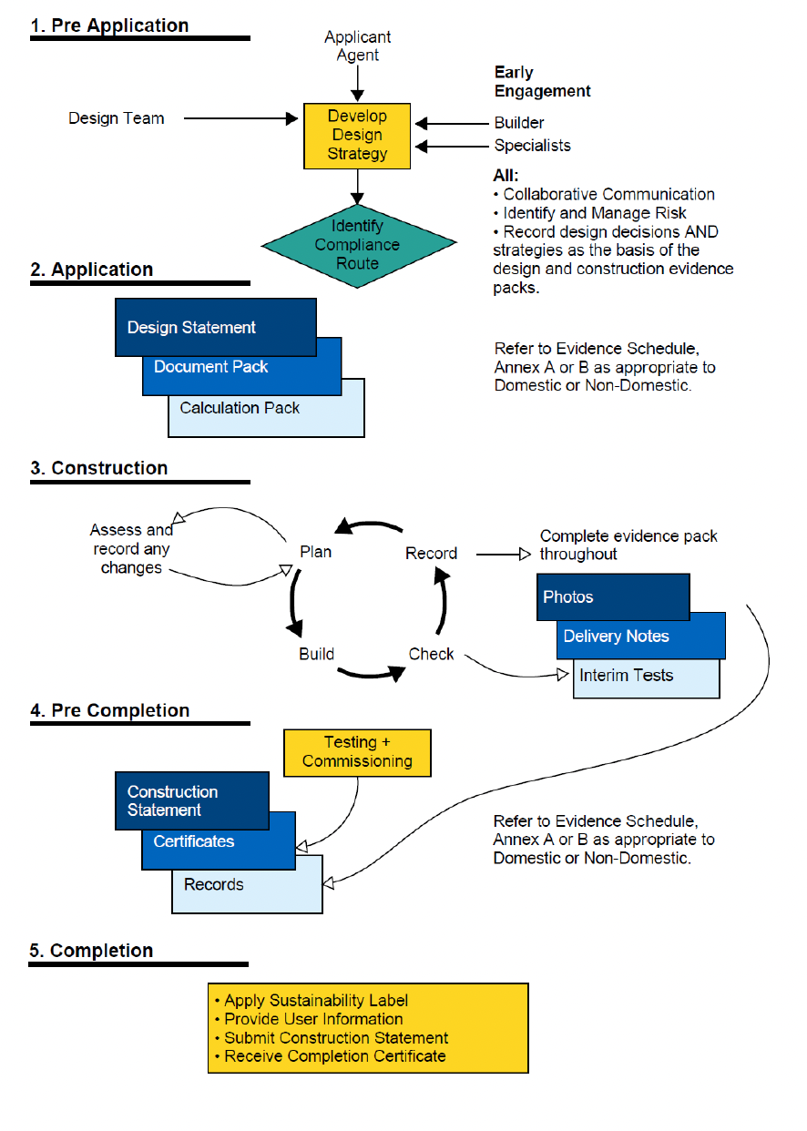
1. Pre Application
Applicant Agent
Design Team
Develop Design Strategy
Early Engagement
Builder
Specialists
All:
•Collaborative Communication
•Identify and Manage Risk
•Record design decisions AND strategies as the basis of the design and construction evidence packs.
Identify Compliance Route
2. Application
Design Statement
Document Pack
Calculation Pack
Refer to Evidence Schedule, Annex A or B as appropriate to Domestic or Non-Domestic.
3. Construction
Assess and record any changes
Plan
Record
Complete evidence pack throughout
Photos
Delivery Notes
Interim Tests
Check
Build
4. Pre Completion
Construction Statement
Certificates
Testing + Commissioning
Records
Refer to Evidence Schedule, Annex A or B as appropriate to Domestic or Non-Domestic.
5. Completion
•Apply Sustainability Label
•Provide User Information
•Submit Construction Statement
•Receive Completion Certificate
Energy and Environmental Requirements
#Source page 5
Energy and environmental standards
Since the introduction of national building regulations to Scotland in 1964, there have been energy standards, in one form or another. Initially these only applied to the external fabric of certain residential buildings and were minimal in nature. Later, they evolved to take account of commercial and industrial non-domestic buildings and to address the energy efficiency of those building services essential to provide comfort to occupiers of buildings.
Prior to 2000, reviews of energy standards were less frequent, with the outcome of such reviews resulting in modest standards that kept pace with change, but which could be comfortably achieved by all aspects of industry. An impact assessment carried out on subsequent changes over this era would show a cost-benefit for modest improvements which would pay back quickly through reduction in the occupier’s energy bills.
Following the introduction of The 2003 Act and our current system of building standards in May 2005, energy standards within section 6 of the Building Standards Technical Handbooks were reviewed and improved in 2007, 2010, 2015 and most recently in 2023. For new buildings, 2007 saw the introduction of a single means of demonstrating compliance based on calculated carbon dioxide emission targets, using the Standard Assessment Procedure (SAP) for dwellings and the Simplified Building Energy Model (SBEM) (or equivalent) for non-domestic buildings.
Each review introduced further staged improvement to energy standards and related changes on topics such as ventilation. It is assessed that emissions arising from energy use in new buildings constructed to the 2023 standards are, on aggregate, around 32% lower for new homes and 20% lower for new non-domestic buildings, compared to the previous 2015 standards and more than 80% lower than standards in force in 1990, the baseline reporting year for CO2 emissions.
In May 2022, Alex Rowley MSP put forward a draft proposal for a Proposed Building Environmental Standards (Scotland) Bill. This was confirmed in a final proposal of 18 November 2022 for “a Bill to introduce new minimum environmental design standards for all new-build housing to meet a Scottish equivalent to the Passivhaus standard, in order to improve energy efficiency and thermal performance”.
In December 2022, Ministers committed to give effect to the Members’ Bill to deliver ‘a Scottish equivalent to the Passivhaus standard’ with a focus on two outcomes:
•Improvements to the setting of energy and environmental (ventilation) performance standards for new buildings, leading to lower energy demand (and reduced running costs) and a healthy indoor environment; and
•Improvements to the design and construction process to give greater assurance that compliance, and therefore the performance sought, is delivered in practice.
The Building (Procedure) (Scotland) Amendment Regulations 2024, refers specifically to the following energy and environmental standards:
Section 3 – Environment:
•Heating (Standard 3.13)
•Ventilation (Standard 3.14)
•Overheating Risk (Standard 3.28)
Section 6 – Energy:
•Energy Demand (Standard 6.1)
•Building Insulation Envelope (Standard 6.2)
•Heating System (Standard 6.3)
•Insulation of Pipes, Ducts & Vessels (Standard 6.4)
•Artificial & Display Lighting (Standard 6.5)
•Mechanical Ventilation and Air Conditioning (Standard 6.6)
•Commissioning Building Services (Standard 6.7)
•Metering (Standard 6.10)
Section 7 – Sustainability:
•Statement of Sustainability (Standard 7.1)
•Electric Vehicle Charging (Standard 7.2)
Clauses from the Technical Handbooks are referenced in this handbook and schedules A and B. Always refer to the current applicable Standards and Technical Handbooks available from www.gov.scot/collections/building-standards/
Key energy and environmental considerations
Measures fundamental to energy and environmental compliance and assurance include ensuring air tightness, using high-performance windows, doors and insulation products, minimising thermal bridging, providing ventilation that preserves indoor air quality with minimal heat loss, optimising heating, hot-water and power efficiency, and preventing overheating during warm periods.
Design Statement requirements
The Design Statement should include design information to demonstrate that the energy & environmental design presented as part of the building warrant application is achieving the requirements of the relevant mandatory standards.
Schedules A (Domestic) & B (Non-Domestic) of the handbook provide practical guidance on the information to be collated for the relevant mandatory standards respectively.
Each relevant mandatory standard must be addressed in the Design Statement, but supporting information may be collated once and referenced accordingly.
Supporting information should be provided to show that each part of the standard has been considered in the building warrant design by referencing submitted drawings / specification / layout / schedules as appropriate.
Key roles and responsibilities and risk management should also be considered at the design stage, which should be included as part of the Design Statement.
Design information to be gathered and managed
Building and product information, for example:
•Design drawings (floor plans, elevations, and sections, etc)
•Material specifications and product datasheets (insulation products, window and door performance, etc)
•Performance calculations (U-Values, Psi Values, etc)
•Energy modelling results
System specifications, for example:
•Heating system design and efficiency
•Hot water system design and efficiency
•Ventilation system design
Construction Statement requirements
The Construction Statement should include evidence during construction as well as ‘as built’ records to demonstrate that the completed building design is achieving the requirements of the relevant energy & environmental mandatory standards.
Schedules A (Domestic) & B (Non-Domestic) of the handbook provide practical guidance on the evidence to be collated for each mandatory standard respectively.
Supporting evidence provided should be cross referenced to the Design Statement as part of the completion submission. Evidence will generally include product and delivery information, as well as photographic evidence of building elements, as appropriate.
Photographs should clearly show installation location and arrangement, related construction details, legible readings, product labels and model numbers, visible measurements (e.g. using a tape measure or ruler) and be taken before covering critical elements. At least 2–5 photos per building element or system depending on complexity, should be provided.
Roles and responsibilities and risk management should also be reconsidered during the planning and build phases of construction, which should be updated and included as part of the Construction Statement.
Construction evidence to be gathered and managed
•Delivery notes for materials, products, equipment, etc
•Photos of building elements and system installations at key stages
•Product labels showing type, specification, etc
•Testing results, namely air tightness, as required by mandatory standards, etc
•Commissioning certificates
Managing changes during construction
Any changes to the design of the building, or associated specification of elements, during construction, must be:
•Submitted for assessment through an amendment to building warrant application
•Documented in the Construction Statement
•Tested to confirm they still meet standards
•Agreed with the Verifier and the Approved Certifier of Design. The amendment to building warrant procedure must also be followed.
Changes typically not requiring an amendment to building warrant are substitutions that maintain or improve performance associated with the relevant Energy or Environmental Mandatory Standard(s).
Changes typically requiring an amendment to building warrant are substitutions that affect energy or environmental performance and associated aspects of the building.
The Verifier will confirm if an amendment to building warrant is required for any changes.
Resources
Specialist support:
•Certifiers of Design (Energy)
•Energy consultants
•Testing specialists
•Commissioning specialists
•Building Performance specialists
•Third Party Certifiers
Verifier / Building Standards Team:
Your local authority building standards department
Building Standards Division:
Scottish Government guidance and technical handbooks available here
Building Standards Hub:
Scottish Building Standards Hub | SBSH
Compliance Plan Approach:
Compliance Plan Approach Workstream
Certification of Design:
Building Standards Certification Handbook
Building Services Compliance Guide:
Domestic Building Services Compliance Guide
Further sources:
•CIBSE Guidance Documents (TM23, Guide B, etc.)
•Passivhaus Trust (Guidance & Learning Hub, etc.)
•Product Certification Schemes (BBA, BM TRADA, etc.)
Schedule A – Domestic
#Source page 6
Energy and Environmental Compliance
Guidance on gathering information and evidence to support the production of Design and Construction Statements
Section 3 - Environment
Heating (Standard 3.13)
Design Information to support the production of the Energy and Environmental Design Statement
Supporting design information includes, but should not be limited to:
Design drawings
•Floor plans showing heating layouts
Specifications
•Heating system type
•Heat unit specification
•Heat emitters specification
Product datasheets
•Heating unit manufacturer’s literature
•Heating emitters manufacturer’s literature
Performance calculations
•Heat loss calculation to a recognised standard
•Heating system capacity calculation
Systems design
•Heating system performance specification
•Heating system capability to be upgraded
Construction Evidence to support the production of the Energy and Environmental Construction Statement
Construction evidence should include, but not be limited to:
Photographs
•Heating system as installed
Delivery notes
•Heat units
•Heat emitters
Product labels
•Heat units
•Heat emitters
Testing results and reports
•Heating system installation records
Commissioning certificates
•Heating system commissioning
Handover information
•Heating system user handbook / manual
•Heating system maintenance requirements
Ventilation (Standard 3.14)
Design Information to support the production of the Energy and Environmental Design Statement
Supporting design information includes, but should not be limited to:
Design drawings
•Floor plans showing ventilation layouts (units, fans, ducting, etc)
•Layouts showing air transfer paths between rooms
•Layouts showing background ventilation
•Ventilation schedules
•Window/door schedules showing opening area requirements
•Layouts showing location of extract fans
•Layouts showing location of CO2 monitors
•Layouts showing humidistat controls
•Layouts showing access for commissioning
•Testing and commissioning schedule
•Layouts showing access for maintenance
Specifications
•Ventilation system type
•Ventilation fan(s) specification
•Minimum dimension from underside of door leaf to floor required
•Background ventilation equivalent area(s)
•CO2 monitor
•Humidistat controls
•Commissioning requirements
Product datasheets
•Ventilation unit manufacturer’s literature
•Fan manufacturer’s literature
•Duct manufacturer’s literature
•Transfer grille manufacturer’s literature
•Windows/doors and any restrictors
Performance calculations
•Ventilation requirement calculation
•Background ventilation calculation
•Purge ventilation calculation
•Extract ventilation rate calculation
•Heat recovery calculation
Systems design
•Ventilation system performance specification (natural, intermittent mechanical or continuous mechanical)
•Ventilation schematic
•Commissiong points schematic
•Written description of how to operate and maintain the ventilation system
Construction Evidence to support the production of the Energy and Environmental Construction Statement
Construction evidence should include, but not be limited to:
Photographs
•Ventilation system as installed
•Ventilation units as installed
•Extract Fans as installed
•Background/trickle vents as installed
•Ducting as installed
•Transfer grilles as installed
•CO2 monitor as installed
•Humidistat controls as installed
•Demonstrate dimension from underside of door leaf to floor
•Demonstrate opening areas of windows/doors/ventilators
•Ventilation filters installed
Delivery notes
•Ventilation units
•Extract Fans
•Ducting
•Transfer grilles
•CO2 monitor
•Humidistat controls
Product labels
•Ventilation units
•Extract Fans
•CO2 monitor
•Humidistat controls
Testing results and reports
•Ventilation system installation records
Commissioning certificates
•Ventilation system commissioning reports
•Demonstrate accordance with ventilation schedules
Handover information
•Ventilation system user handbook / manual
•Ventilation system maintenance requirements
Overheating Risk (Standard 3.28)
Design Information to support the production of the Energy and Environmental Design Statement
Supporting design information includes, but should not be limited to:
Design drawings
•Drawings and / or schedules illustrating g-values of specific windows/doors (where g-value varies across the project)
•Drawing showing opening free area of windows
•Elevations and/or detail drawings as required to show shading measures, with sizes noted and orientation
Specifications
•Glazing Specification with g-value(s) required
•Any shading devices / products
Performance calculations
•Glazing calculation(s) showing g-value to 2 decimal places (calculated to EN 410)
•Assessment on number of exposed facades and arrangement of openings which provide ventilation to apartments or other habitable spaces
Energy modelling
Overheating Risk – Simple method
Including:
•Dimensioned plan drawings
•Glazing/floor area ratio calculation
•G-valve compensation calculation(s), where required
Overheating Risk – Dynamic thermal analysis modelling including:
•TM59 Dynamic thermal modelling report
•Reference to drawings recording the building geometry used
•Schedule of the fabric U-values, window U-values and g-values, ventilation strategy, permanent shading devices that have been used in the simulation
•Specifications or manufacturer's data sheets for the fabric U-values, window U-values and g-values, ventilation strategy,
•Details of permanent shading devices
Systems design
•Statement on practicality issues considered and assessed for developing the overheating mitigation strategy
•Written description of the overheating mitigation systems included in the design (including any provisions made to address site-specific and environmental constraints) and how to operate and maintain them
•Description of user control for boost vent & schedules demonstrating boost ventilation rates
Construction Evidence to support the production of the Energy and Environmental Construction Statement
Construction evidence should include, but not be limited to:
Photographs
•All elevations as built
•All glazing unit label(s) as installed in window / door (showing reference to demonstrate correct unit is installed in the correct component, on correct elevation)
•Windows / doors (with any restrictors fitted) demonstrating free area requirement
•Any shading devices as installed
Delivery notes
•Window / door supplier(s)
•Glazing supplier(s)
•Any shading devices
Product labels
•Window / door supplier(s)
•Glazing supplier(s)
•Any shading devices
Handover information
•User handbook/manual with written description of overheating mitigation systems, including any provisions made to address site-specific and environmental constraints, as well as how to operate and maintain them
Section 6 - Energy
Energy Demand (Standard 6.1)
Design Information to support the production of the Energy and Environmental Design Statement
Supporting design information includes, but should not be limited to:
Energy modelling
Energy Demand Calculation including:
•Energy model following UK National Calculation Methodology
•Building layout (showing internal floor area), elevations (showing windows, doors and roof profiles) and section drawings (showing floor to floor height and roof profiles)
•3D model or calculation showing external wall, floor and roof areas
•Site plans showing the orientation and shading objects
•Full address and postcode and weather file used
•Specification of any low and zero carbon electricity generators
Construction Evidence to support the production of the Energy and Environmental Construction Statement
Construction evidence should include, but not be limited to:
Photographs
•Low and zero carbon generating technology (including any inverters for solar PV) as installed
Delivery notes
•Low and zero carbon generating technology (including any inverters for solar PV) as installed
Product labels
•Low and zero carbon generating technology showing manufacturer and model name (including any inverters for solar PV) as installed
Testing results and reports
•As built energy demand calculation
Building Insulation Envelope (Standard 6.2)
Design Information to support the production of the Energy and Environmental Design Statement
Supporting design information includes, but should not be limited to:
Design drawings
•Detailed drawings of all external buildups with the material thicknesses and products (material & performance) clearly stated and repeating thermal bridges shown
•Drawings that clearly show the locations of all buildups
•General arrangement drawings clearly identifying exposed edges and instances of abutting elements
•Detailed drawings of cavity separating walls. The material specifications and material thickness should be clearly shown
•Window component drawings, elevations and schedules
•Plan, section and detail drawings of all key non-repeating thermal bridges and their location with airtight, thermal and windtight lines shown
•Markups or labelled model showing the lengths/quantities of all non-repeating thermal bridges
•Schedule of all thermal bridges with justification for their assigned psi/chi value (demonstrate that value assigned is conservative stating its source, or provide a calculation in accordance with BS EN ISO 10211: 2017)
Specifications
•Insulation products to be used including thickness
•State that insulation is to be continuous, with no gaps or voids over 3mm, not be over compressed and be in two layers with offset joints
•Insulation, wind & airtight products including tapes and seals to be used at junctions
•Other products, including wall ties, masonry support angles and any other thermal bridging elements referencing thermal conductivity of products and any thermal shims or breaks required
•All windows, doors and rooflights with manufacturer, model, height, width, frame depth & thickness, glass U-value, glazing g-value, frame U-value and glazing to frame psi value
•Products to be used to form and repair the airtight layer stating that membranes, tapes & seals should be applied to firm, solid and clean substrate to aid application and that gaps greater than 6mm in the substrate are not permitted
•Products used to seal around service penetrations, window and door openings to the airtight line
•Requirement for air tightness testing, the target to be met and the air testing strategy
•Any interim air tests with their purpose, process and when they should occur
Product datasheets
•Insulation and any other relevant products that includes thermal conductivity and moisture absorptivity where relevant
•Products used for sealing any perimeter cavities
•All air tightness products used (including any membranes, boards, tapes, etc) stating their air permeability and compatibility with other materials used on the building
•Window/Door/Rooflight datasheet with air tightness class stated classification according to BS 12207 (typically class 4)
Performance calculations
•U-Value calculations calculated either by using insulation to a thickness derived from manufacturers’ data relating to thermal conductivities (W/mK) and thermal transmittances (U-values: W/m2K) certified by a notified body, or in accordance with BS EN ISO 6946:2017 and for floors adjacent to ground/basements BS EN ISO 13370: 2017
•Where the 'space heating demand limit' approach is taken for new dwellings, the reported space heating demand from the SAP model must be below the 'dwelling space heating demand limit'
•Calculation to show the overall window/door element U-value using BS EN ISO 10077-1: 2017, BS EN ISO 10077-2: 2017 or (for rooflights) BS EN ISO 12567-2: 2005
•Thermal bridge calculation(s) demonstrating minimum surface temperature is within the minimum requirement
Construction Evidence to support the production of the Energy and Environmental Construction Statement
Construction evidence should include, but not be limited to:
Photographs
•Each building element (different wall types, roof, soffits, etc.)
•Show large overall section of element being represented
•Insulation products installed showing type and thickness
•Show that the insulation is continuous, with no gaps or voids over 3mm, not over compressed, cut cleanly and in two layers with offset joints
•Show that insulation is cut neatly around service penetrations
•Each instance of a cavity seal around the perimeter
•Show large overall section of element being represented
•Show that the cavity is fully filled with a material that limits air movement
•Each window/door/rooflight product type installed showing fixings, interface with airtight layer, interface with insulation and overall installation (NB it is not necessary to photograph all windows & doors)
•Each of the key junction details as agreed with the verifier to show installation is as designed
•Show airtight line / products as installed, fully seated with no gaps or breaks
•Show insulation well installed with no voids or gaps over 3mm
•Any bridging elements (column, masonry supports etc.) to be photographed with a tape measure to demonstrate it has been installed in line with the design
•Typical service penetrations and any additional instances agreed with the verifier
Delivery notes
•For each insulation product including manufacturer, product name and lamda value
•For each window/door/rooflight product including manufacturer, product name and lamda value
•For all airtight layer membranes, tapes & seals
Product labels
•For each insulation product including manufacturer, product name and lamda value
•For each window/door/rooflight product including manufacturer, product name and lamda value
•For all airtight layer membranes, tapes & seals
Testing results and reports
•As built general arrangement drawings, including elevations and window/door schedules
•As built schedule of thermal bridges with psi values aligned to the as built details
•Air tightness test certificate and method statement (It is not necessary to provide any interim tests in the final evidence pack. The builder may choose to hold interim results in their evolving evidence pack as part of their wider risk and quality management process. If so, their status should be clearly identified.)
Heating System (Standard 6.3)
Design Information to support the production of the Energy and Environmental Design Statement
Supporting design information includes, but should not be limited to:
Design drawings
•Heating system design drawings
•Mechanical schedule
•Controls drawings
Specifications
•Mechanical specification
•Controls specification
Product datasheets
•Detailed performance specification or product datasheet of heating system components (giving COP/SCOP (to BS EN 14511-2), if applicable, aligned with system design temperature
Systems design
•Design in line with guidance in Compliance Guide in respect to efficiency of heat source, system circulation, system preparation, hot water storage, interlock, zoning, time & temperature controls, flowrate controls, supply temperature, installation, etc
Construction Evidence to support the production of the Energy and Environmental Construction Statement
Construction evidence should include, but not be limited to:
Photographs
•Heating system as installed
•Heating plant showing model plates
Delivery notes
•Heat units
•Heat emitters
Product labels
•Heat units
•Heat emitters
Testing results and reports
•As installed heating system modelling calculations
•Heating system installation records
Commissioning certificates
•Heating system commissioning
Handover information
•As installed heating system drawings, schedules and specifications.
•Heating system user handbook / manual
•Heating system maintenance requirements
Insulation of Pipes, Ducts & Vessels (Standard 6.4)
Design Information to support the production of the Energy and Environmental Design Statement
Supporting design information includes, but should not be limited to:
Specifications
•Pipes/ducts - Specification noting insulation products to be used including thickness
Product datasheets
•Insulation product datasheet or detailed performance specification
Performance calculations
•Vessels - Standing heat loss calculations, backed up with specification of insulation including thickness and thermal conductivity and insulation product datasheet or detailed performance specification
Systems design
•Demonstrate that pipes ducts and vessels have been addressed as provided in the section 9 of the Non-domestic Building Services Compliance Guide for Scotland
Construction Evidence to support the production of the Energy and Environmental Construction Statement
Construction evidence should include, but not be limited to:
Photographs
•Hot water storage vessel as installed
•Insulation thicknesses to pipes and ducts as installed
•Show no voids or gaps greater than 3mm between or under insulation
Delivery notes
•Hot water storage vessel as installed
•Insulation product(s)
Product labels
•Hot water storage vessel confirming capacity, standing heat loss and heat exchanger performance
•Insulation product(s) including manufacturer and lambda value
Artificial & Display Lighting (Standard 6.5)
Design Information to support the production of the Energy and Environmental Design Statement
Supporting design information includes, but should not be limited to:
Design drawings
•Lighting layouts showing number of luminaires and lighting controls
Specifications
•Controls description/specification
Product datasheets
•Datasheet/ luminaire schedule confirming efficacy (lm/W)
Performance calculations
•LENI calculation, if applicable
Systems design
•Demonstrate that internal lighting efficiency has been addressed as provided in the section 13 of the Domestic Building Services Compliance Guide for Scotland
Construction Evidence to support the production of the Energy and Environmental Construction Statement
Construction evidence should include, but not be limited to:
Photographs
•Each luminaire type as showing extent in typical room
Delivery notes
•Each luminaire type as installed
•Each controls type as installed
Handover information
•Controls user manual(s) / manufacturer’s literature
Mechanical Ventilation and Air Conditioning (Standard 6.6)
Design Information to support the production of the Energy and Environmental Design Statement
Supporting design information includes, but should not be limited to:
Design drawings
•Drawings and / or schedules illustrating g-values of specific windows (where g-value varies across the project)
•Drawing showing opening free area of windows/doors
•Elevations and/or detail drawings as required to show shading measures, with sizes noted
•Ventilation schedules/schematics/ layouts showing system requirements and performance
•Drawings & specification noting filter type and demonstrating sufficient space for maintenance
•Drawings & specification noting controller location & controller specification
•Drawings illustrating duct lengths and access for commissioning and maintenance
•Details showing any interface of ducts with external envelope and airtight line
•Drawings or schematics showing location of any dampers
Specifications
•Glazing Specification with g-value(s) required
•Description of user control for boost vent & schedules demonstrating boost ventilation rates
•Any shading products required
•Performance specification of any proposed equipment
•Any insulation products to ducting including type, lambda value and thickness - state that insulation is to be continuous with no gaps or voids over 3mm and insulation must not be over compressed
•Any airtight dampers
Product datasheets
•Ventilation equipment
•Insulation to ducting including any tapes, vapour barriers, etc
Performance calculations
•Glazing calculation certificate showing g-value to 2 decimal places (calculated to EN 410)
•System efficiency calculated at commissioned design flow rate
Systems design
•If overheating risk assessment requires cooling, demonstrate that mechanical ventilation and air conditioning efficiency has been addressed as provided in the sections 10 and 11 of the Domestic Building Services Compliance Guide for Scotland
Construction Evidence to support the production of the Energy and Environmental Construction Statement
Construction evidence should include, but not be limited to:
Photographs
•Ventilation units as installed showing location(s)
•Filters as installed identifying type
•Show MVHR / AHU installation with sufficient space for filter removal
•Show controller switch location and controller
•Show length of cold ducts inside and warm ducts outside the thermal envelope
•Demonstrate no voids or gaps greater than 3mm between or under insulation
•Show ducts sealed to airtight line of building and duct to MVHR / AHU
•Repeat the above for each type of ventilation system used
Delivery notes
•Ventilation units as installed
•Any filters as installed
•Any controls equipment as installed
•Insulation products as installed
•Ducting as installed
Product labels
•Ventilation units as installed
•Any filters as installed
•Any controls equipment as installed
•Insulation products as installed
•Ducting as installed
Testing results and reports
•As installed system efficiency calculation
Commissioning certificates
•Commissioning reports demonstrating ventilation has been commissioned in line with the ventilation schedules
•A +5% tolerance is acceptable
•Not more than 10% imbalance between total supply and extract
Handover information
•As installed drawings, schedules, specifications
Commissioning Building Services (Standard 6.7)
Design Information to support the production of the Energy and Environmental Design Statement
Supporting design information includes, but should not be limited to:
Design drawings
•Layouts showing access for commissioning, inspection and maintenance of services
Specifications
•Testing & commissioning schedule
•Specifications detailing commissioning requirements for MEP systems and any active architectural systems (e.g. powered ventilation openings)
•Identify any enhanced load, duration and/or multi-system tests that will be required to demonstrate compliance, in particular for made-to-order equipment or less common systems
Construction Evidence to support the production of the Energy and Environmental Construction Statement
Construction evidence should include, but not be limited to:
Testing results and reports
•Report on the outcomes of any commissioning review
•Commissioning statements, including commentary and records of the testing and commissioning programme and compliance or variations from the testing and commissioning requirement set out in the design statement
Commissioning certificates
•Commissioning certificates for all systems and services
Note – some commissioning evidence will often be included under other sections of the construction statement, and should be clearly referenced as required
Metering (Standard 6.10)
Design Information to support the production of the Energy and Environmental Design Statement
Not applicable to domestic buildings.
Construction Evidence to support the production of the Energy and Environmental Construction Statement
Not applicable to domestic buildings.
Section 7 - Sustainability
Statement of Sustainability (Standard 7.1)
Design Information to support the production of the Energy and Environmental Design Statement
Supporting design information includes, but should not be limited to:
Design drawings
•Provide plans, sections, elevations, details, schedules, specification, etc, as appropriate to demonstrate level of sustainability proposed
Specifications
•Specify level of sustainability proposed:
•Bronze level
•Bronze Active level
•Silver level
•Silver Active level
•Gold level
Construction Evidence to support the production of the Energy and Environmental Construction Statement
Construction evidence should include, but not be limited to:
Photographs
•Statement of sustainability (sustainability label, or SL) fixed to the building, including the level of sustainability achieved, in a location that is readily accessible, protected from weather and not easily obscured
•Other photographs as appropriate for the level of sustainability to demonstrate associated elements as built/as installed
Testing results and reports
•Calculations as appropriate for the level of sustainability to demonstrate associated elements as built/as installed
Handover information
•Quick start guides/guidance/labels as appropriate for the level of sustainability to demonstrate associated elements as built/as installed
Electric Vehicle Charging (Standard 7.2)
Design Information to support the production of the Energy and Environmental Design Statement
Supporting design information includes, but should not be limited to:
Design drawings
•Schedule of equipment
•Location of charge points shown on plan drawings
•Assignment of any car parking spaces (if applicable)
•Duct and chamber layouts and sizes based upon the confirmed schematic arrangement and type of cabling needed to meet the required power supply at outlets for any enabling infrastructure
Specifications
•Specification of equipment
Product datasheets
•Datasheets for charge points showing nominal rated output and compliance with BS 7671 and IET’s ‘Code of Practice: Electric Vehicle Charging Equipment Installation’
Performance calculations
•Electrical demand calculation
Systems design
•Written quotation for the cost of electrical supply to development site (if applicable)
Construction Evidence to support the production of the Energy and Environmental Construction Statement
Construction evidence should include, but not be limited to:
Photographs
•Each type of equipment as installed
•Charge point locations as installed
•Electrical meter showing power output from charge points
•Assignment of any car parking spaces (if applicable)
•Universal socket, indicator/visual display, manufacturer and model
•Clear, unobstructed ducts and champers with pulling lines for any enabling infrastructure
Commissioning certificates
•Commissioning information for the charge point(s) and any associated control equipment
Handover information
•Quick Start guides
•Manufacturer’s literature on installed products
•As built drawings showing the location of all installed ductwork and equipment, also identifying all enabling infrastructure which will support the addition of charge points in the future
Schedule B – Non-Domestic
#Source page 7
Energy and Environmental Compliance
Guidance on gathering information and evidence to support the production of Design and Construction Statements
Section 3 - Environment
Heating (Standard 3.13)
Design Information to support the production of the Energy and Environmental Design Statement
Not applicable to non-domestic buildings.
Refer to Schedule A – Domestic for any mixed-use buildings containing dwellings.
Construction Evidence to support the production of the Energy and Environmental Construction Statement
Not applicable to non-domestic buildings.
Refer to Schedule A – Domestic for any mixed-use buildings containing dwellings.
Ventilation (Standard 3.14)
Design Information to support the production of the Energy and Environmental Design Statement
Supporting design information includes, but should not be limited to:
Design drawings
•Floor plans showing ventilation layouts (units, fans, ducting, etc)
•Layouts showing background ventilation
•Layouts showing air transfer paths between rooms
•Ventilation schedules
•Window/door schedules showing opening area requirements
•Layouts showing location of extract fans
•Layouts showing location of CO2 monitors
•Layouts showing humidistat controls
•Layouts showing access for commissioning
•Testing and commissioning schedule
•Layouts showing access for maintenance
Specifications
•Opening areas of ventilators
•Ventilation system type
•Ventilation fan(s) specification
•Louvres, grilles, meshes and other opening obstructions
•Minimum dimension from underside of door leaf to floor required
•Background ventilation equivalent area(s)
•CO2 monitor
•Humidistat controls
•Commissioning requirements
Product datasheets
•Ventilation unit manufacturer’s literature
•Fan manufacturer’s literature
•Duct manufacturer’s literature
•Transfer grille manufacturer’s literature
•Windows/doors and any restrictors
Performance calculations
•Ventilator opening area requirement(s)
•Ventilation requirement calculation
•Background ventilation calculation
•Purge ventilation calculation
•Extract ventilation rate calculation
•Heat recovery calculation
Systems design
•Ventilation system performance specification (natural, intermittent mechanical or continuous mechanical)
•Ventilation schematic
•Commissiong points schematic
•Written description of how to operate and maintain the ventilation system
Construction Evidence to support the production of the Energy and Environmental Construction Statement
Construction evidence should include, but not be limited to:
Photographs
•Ventilation system as installed
•Ventilation units as installed
•Extract Fans as installed
•Background/trickle vents as installed, located in ventilator/window/door
•Ducting as installed
•Transfer grilles as installed
•Louvres, grilles, meshes and other opening obstructions as installed
•CO2 monitor as installed
•Humidistat controls as installed
•Demonstrate dimension from underside of door leaf to floor
•Demonstrate opening areas of windows/doors/ventilators
•Ventilation filters installed
•Access for maintenance
Delivery notes
•Ventilation units
•Extract Fans
•Ducting
•Transfer grilles
•Louvres, grilles, meshes and other opening obstructions
•CO2 monitor
•Humidistat controls
•Any filters
Product labels
•Ventilation units
•Extract Fans
•Background/trickle Vents
•CO2 monitor
•Humidistat controls
Testing results and reports
•Ventilation system installation records
Commissioning certificates
•Ventilation system commissioning reports
•Demonstrate accordance with ventilation schedules
Handover information
•Ventilation system user handbook / manual
•Ventilation system maintenance requirements
Overheating Risk (Standard 3.28)
Design Information to support the production of the Energy and Environmental Design Statement
Supporting design information includes, but should not be limited to:
Design drawings
•Drawings and / or schedules illustrating g-values of specific windows/doors (where g-value varies across the project)
•Drawing showing opening free area of windows
•Elevations and/or detail drawings as required to show shading measures, with sizes noted and orientation
Specifications
•Glazing Specification with g-value(s) required
•Any shading devices / products
Performance calculations
•Glazing calculation(s) showing g-value to 2 decimal places (calculated to EN 410)
•Assessment on number of exposed facades and arrangement of openings which provide ventilation to apartments or other habitable spaces
Energy modelling
Overheating Risk – Simple method
Including:
•Dimensioned plan drawings
•Glazing/floor area ratio calculation
•G-valve compensation calculation(s), where required
Overheating Risk – Dynamic thermal analysis modelling including:
•TM59 Dynamic thermal modelling report
•Reference to drawings recording the building geometry used
•Schedule of the fabric U-values, window U-values and g-values, ventilation strategy, permanent shading devices that have been used in the simulation
•Specifications or manufacturer's data sheets for the fabric U-values, window U-values and g-values, ventilation strategy,
•Details of permanent shading devices
Systems design
•Statement on practicality issues considered and assessed for developing the overheating mitigation strategy
•Written description of the overheating mitigation systems included in the design (including any provisions made to address site-specific and environmental constraints) and how to operate and maintain them
•Description of user control for boost vent & schedules demonstrating boost ventilation rates
Construction Evidence to support the production of the Energy and Environmental Construction Statement
Construction evidence should include, but not be limited to:
Photographs
•All elevations
•All glazing unit label(s) as installed in window / door (showing reference to demonstrate correct unit is installed in the correct component, on correct elevation)
•Windows / doors (with any restrictors fitted) demonstrating free area requirement
•Any shading devices as installed
Delivery notes
•Window / door supplier(s)
•Glazing supplier(s)
•Any shading devices
Product labels
•Window / door supplier(s)
•Glazing supplier(s)
•Any shading devices
Handover information
•User handbook/manual with written description of overheating mitigation systems, including any provisions made to address site-specific and environmental constraints, as well as how to operate and maintain them
Section 6 - Energy
Energy Demand (Standard 6.1)
Design Information to support the production of the Energy and Environmental Design Statement
Supporting design information includes, but should not be limited to:
Energy modelling
Energy Demand Calculation including:
•Energy model following UK National Calculation Methodology
•Building layout (showing internal floor area), elevations (showing windows, doors and roof profiles) and section drawings (showing floor to floor height and roof profiles)
•3D model or calculation showing external wall, floor and roof areas
•Site plans showing the orientation and shading objects
•Schedule of shading factors and their justification
•Full address and postcode and weather file used
•Specification of any low and zero carbon electricity generators
•Schedule of management features proposed
Construction Evidence to support the production of the Energy and Environmental Construction Statement
Construction evidence should include, but not be limited to:
Photographs
•Low and zero carbon generating technology (including any inverters for solar PV) as installed
•Main distribution board including evidence of power factor achieved
•Automatic Monitoring and Targeting settings (where relevant)
Delivery notes
•Low and zero carbon generating technology (including any inverters for solar PV) as installed
Product labels
•Low and zero carbon generating technology showing manufacturer and model name (including any inverters for solar PV) as installed
•Testing results and reports
•As built energy demand calculation
Building Insulation Envelope (Standard 6.2)
Design Information to support the production of the Energy and Environmental Design Statement
Supporting design information includes, but should not be limited to:
Design drawings
•Detailed drawings of all external buildups with the material thicknesses and products (material & performance) clearly stated and repeating thermal bridges shown
•Drawings that clearly show the locations of all buildups
•Plan and section drawings showing the continuous thermal envelope line
•General arrangement drawings clearly identifying exposed edges and instances of abutting elements
•Detailed drawings of cavity separating walls. The material specifications and material thickness should be clearly shown
•Window component drawings, elevations and schedules
•Plan, section and detail drawings of all key non-repeating thermal bridges and their location with airtight, thermal and windtight lines shown
•Markups or labelled model showing the lengths/quantities of all non-repeating thermal bridges
•Schedule of all thermal bridges with justification for their assigned psi/chi value (demonstrate that value assigned is conservative stating its source, or provide a calculation in accordance with BS EN ISO 10211: 2017)
Specifications
•Insulation products to be used including thickness
•State that insulation is to be continuous, with no gaps or voids over 3mm, not be over compressed and be in two layers with offset joints
•Insulation, wind & airtight products including tapes and seals to be used at junctions
•Other products, including wall ties, masonry support angles and any other thermal bridging elements referencing thermal conductivity of products and any thermal shims or breaks required
•All windows, doors and rooflights with manufacturer, model, height, width, frame depth & thickness, glass U-value, glazing g-value, frame U-value and glazing to frame psi value
•Products to be used to form and repair the airtight layer stating that membranes, tapes & seals should be applied to firm, solid and clean substrate to aid application and that gaps greater than 6mm in the substrate are not permitted
•Products used to seal around service penetrations, window and door openings to the airtight line
•Requirement for air tightness testing, the target to be met and the air testing strategy
•Any interim air tests with their purpose, process and when they should occur
Product datasheets
•Insulation and any other relevant products that includes thermal conductivity and moisture absorptivity where relevant
•Products used for sealing any perimeter cavities
•All air tightness products used (including any membranes, boards, tapes, etc) stating their air permeability and compatibility with other materials used on the building
•Window/Door/Rooflight datasheet with air tightness class stated classification according to BS 12207 (typically class 4)
Performance calculations
•U-Value calculations calculated either by using insulation to a thickness derived from manufacturers’ data relating to thermal conductivities (W/mK) and thermal transmittances (U-values: W/m2K) certified by a notified body, or in accordance with BS EN ISO 6946:2017 and for floors adjacent to ground/basements BS EN ISO 13370: 2017
•Calculation to show the overall window/door element U-value using BS EN ISO 10077-1: 2017, BS EN ISO 10077-2: 2017 or (for rooflights) BS EN ISO 12567-2: 2005
•Thermal bridge calculation(s) demonstrating minimum surface temperature is within the minimum requirement
Construction Evidence to support the production of the Energy and Environmental Construction Statement
Construction evidence should include, but not be limited to:
Photographs
•For each building element (different wall types, roof, soffits, etc.).
•Show large overall section of element being represented
•Insulation products installed showing type and thickness
•Show that the insulation is continuous, with no gaps or voids over 3mm, not over compressed, cut cleanly and in two layers with offset joints
•Show that insulation is cut neatly around service penetrations
•For each instance of a cavity seal around the perimeter
•Show large overall section of element being represented
•Show that the cavity is fully filled with a material that limits air movement
•Each window/door/rooflight product type installed showing fixings, interface with airtight layer, interface with insulation and overall installation (NB it is not necessary to photograph all windows & doors)
•Each of the key junction details as agreed with the verifier to show installation is as designed
•Show airtight line / products as installed, fully seated with no gaps or breaks
•Show insulation well installed with no voids or gaps over 3mm
•Any bridging elements (column, masonry supports etc.) to be photographed with a tape measure to demonstrate it has been installed in line with the design
•Typical service penetrations and any additional instances agreed with the verifier
Delivery notes
•For each insulation product including manufacturer, product name and lamda value
•For each window/door/rooflight product including manufacturer, product name and lamda value
•For all airtight layer membranes, tapes & seals
Product labels
•For each insulation product including manufacturer, product name and lamda value
•For each window/door/rooflight product including manufacturer, product name and lamda value
•For all airtight layer membranes, tapes & seals
Testing results and reports
•As built general arrangement drawings, including elevations and window/door schedules
•As built schedule of thermal bridges with psi values aligned to the as built details
•Air tightness test certificate and method statement (It is not necessary to provide any interim tests in the final evidence pack. The builder may choose to hold interim results in their evolving evidence pack as part of their wider risk and quality management process. If so, their status should be clearly identified.)
Heating System (Standard 6.3)
Design Information to support the production of the Energy and Environmental Design Statement
Supporting design information includes, but should not be limited to:
Design drawings
•Heating system design drawings
•Hot water system design drawings
•Mechanical schedule
•Controls drawings
Specifications
•Mechanical specification
•Controls specification
Product datasheets
•Detailed performance specification or product datasheet of heating system components (giving COP/SCOP (to BS EN 14511-2), if applicable, aligned with system design temperature
Performance calculations
•Standing heat loss calculations of hot water cylinders and instantaneous water heaters with storage
Systems design
•Design in line with guidance in Compliance Guide in respect to efficiency of heat source, system circulation, system preparation, hot water storage, interlock, zoning, time & temperature controls, flowrate controls, supply temperature, installation, etc
•Design in line with guidance in Compliance Guide in respect to thermal efficiencies, heat losses and controls.
Construction Evidence to support the production of the Energy and Environmental Construction Statement
Construction evidence should include, but not be limited to:
Photographs
•Heating system as installed
•Heating plant showing model plates
•Equipment, including water heaters, showing model plates
Delivery notes
•Heat units
•Heat emitter
Product labels
•Heat units
•Heat emitters
•Hot water storage vessel or water heater with storage confirming capacity, standing heat loss and heat exchanger performance
Testing results and reports
•As installed heating system modelling calculations
•Heating system installation records
•Datasheet giving COP/SCOP, if applicable, for installed plant
Commissioning certificates
•Heating system commissioning
Handover information
•As installed heating system drawings, schedules and specifications.
•Heating system user handbook / manual
•Heating system maintenance requirements
Insulation of Pipes, Ducts & Vessels (Standard 6.4)
Design Information to support the production of the Energy and Environmental Design Statement
Supporting design information includes, but should not be limited to:
Specifications
•Pipes/ducts - Specification noting insulation products to be used including thickness
Product datasheets
•Insulation product datasheet or detailed performance specification
Performance calculations
•Vessels - Standing heat loss calculations, backed up with specification of insulation including thickness and thermal conductivity and insulation product datasheet or detailed performance specification
Systems design
•Demonstrate that pipes ducts and vessels have been addressed as provided in the section 9 of the Non-domestic Building Services Compliance Guide for Scotland
Construction Evidence to support the production of the Energy and Environmental Construction Statement
Construction evidence should include, but not be limited to:
Photographs
•Hot water storage vessel as installed confirming capacity, standing heat loss and heat exchanger performance
•Insulation thicknesses to pipes and ducts as installed
•Show no voids or gaps greater than 3mm between or under insulation
Delivery notes
•Hot water storage vessel
•Insulation product(s) showing label of product, manufacturer and lambda value
Product labels
•Hot water storage vessel confirming capacity, standing heat loss and heat exchanger performance
•Insulation product(s) including manufacturer and lambda value
Artificial & Display Lighting (Standard 6.5)
Design Information to support the production of the Energy and Environmental Design Statement
Supporting design information includes, but should not be limited to:
Design drawings
•Lighting layouts showing number of luminaires and lighting controls
Specifications
•Controls description/specification
Product datasheets
•Datasheet/ luminaire schedule confirming efficacy (lm/W)
Performance calculations
•LENI calculation, if applicable
Systems design
•Demonstrate that internal lighting efficiency has been addressed as provided in the section 13 of the Domestic Building Services Compliance Guide for Scotland
Construction Evidence to support the production of the Energy and Environmental Construction Statement
Construction evidence should include, but not be limited to:
Photographs
•Each luminaire type as installed showing extent in typical room
Delivery notes
•Each luminaire type as installed
•Each controls type as installed
Handover information
•Controls user manual(s) / manufacturer’s literature
Mechanical Ventilation and Air Conditioning (Standard 6.6)
Design Information to support the production of the Energy and Environmental Design Statement
Supporting design information includes, but should not be limited to:
Design drawings
•Drawings and / or schedules illustrating g-values of specific windows (where g-value varies across the project)
•Drawing showing opening free area of windows/doors
•Elevations and/or detail drawings as required to show shading measures, with sizes noted
•Ventilation schedules/schematics/ layouts showing system requirements and performance
•Drawings & specification noting filter type and demonstrating sufficient space for maintenance
•Drawings & specification noting controller location & controller specification
•Drawings illustrating duct lengths and access for commissioning and maintenance
•Details showing any interface of ducts with external envelope and airtight line
•Drawings or schematics showing location of any dampers
Specifications
•Ventilation equipment
•Glazing Specification with g-value(s) required
•Description of user control for boost vent & schedules demonstrating boost ventilation rates
•Any passive shading strategy/shading products required
•Performance specification of any proposed equipment
•Any insulation products to ducting including type, lambda value and thickness - state that insulation is to be continuous with no gaps or voids over 3mm and insulation must not be over compressed
•Any airtight dampers
Product datasheets
•Ventilation equipment
•Insulation to ducting including any tapes, vapour barriers, etc
Performance calculations
•TM52 (or TM59 for sleeping accommodation) study and report, or
•Overheating report from a Dynamic Simulation Model Glazing calculation certificate showing g-value to 2 decimal places (calculated to EN 410), or
•Simple Method
•System efficiency calculated at commissioned design flow rate
Systems design
•If overheating risk assessment requires cooling, demonstrate that mechanical ventilation and air conditioning efficiency has been addressed as provided in the sections 10 and 11 of the Domestic Building Services Compliance Guide for Scotland
Construction Evidence to support the production of the Energy and Environmental Construction Statement
Construction evidence should include, but not be limited to:
Photographs
•Ventilation units as installed showing location(s)
•Filters as installed identifying type
•Showing MVAC, MVHR / AHU installation with sufficient space for filter removal
•Showing controller switch location and controller
•Showing length of cold ducts inside and warm ducts outside the thermal envelope
•Demonstrate no voids or gaps greater than 3mm between or under insulation
•Show ducts sealed to airtight line of building and duct to MVAC / MVHR / AHU
•Repeat the above for each type of ventilation system used
•Any passive shading installed showing extent of shading on each elevation and depth of each device
Delivery notes
•Ventilation units as installed
•Any filters as installed
•Any controls equipment as installed
•Insulation products as installed
•Ducting as installed
Product labels
•Ventilation units as installed
•Any filters as installed
•Any controls equipment as installed
•Insulation products as installed
•Ducting as installed
Testing results and reports
•As installed system efficiency calculation
Commissioning certificates
•Commissioning reports demonstrating ventilation has been commissioned in line with the ventilation schedules
•A +5% tolerance is acceptable
•Not more than 10% imbalance between total supply and extract
Handover information
•As installed drawings, schedules, specifications
Commissioning Building Services (Standard 6.7)
Design Information to support the production of the Energy and Environmental Design Statement
Supporting design information includes, but should not be limited to:
Design drawings
•Layouts showing access for commissioning, inspection and maintenance of services
Specifications
•Testing & commissioning schedule
•Specifications detailing commissioning requirements for MEP systems and any active architectural systems (e.g. powered ventilation openings)
•Identify any enhanced load, duration and/or multi-system tests that will be required to demonstrate compliance, in particular for made-to-order equipment or less common systems
•Ductwork leakage testing, if applicable, set out in Testing & Commissioning Schedule, and MEP specification as above
Construction Evidence to support the production of the Energy and Environmental Construction Statement
Construction evidence should include, but not be limited to:
Testing results and reports
•Report on the outcomes of any commissioning review
•Commissioning statements, including commentary and records of the testing and commissioning programme and compliance or variations from the testing and commissioning requirement set out in the design statement
Commissioning certificates
•Commissioning certificates for all systems and services
•Note – some commissioning evidence will often be included under other sections of the construction statement, and should be clearly referenced as required
Metering (Standard 6.10)
Design Information to support the production of the Energy and Environmental Design Statement
Supporting design information includes, but should not be limited to:
Design drawings
•Schematics showing metering locations for new or modified energy systems, as applicable
•Metering & Verification Schedule, showing service, purpose and means of monitoring for each meter
Construction Evidence to support the production of the Energy and Environmental Construction Statement
Construction evidence should include, but not be limited to:
Photographs
•Each meter installation
Commissioning certificates
•Commissioning Statements
•As built record of metering including use reference and labelling evidence
Section 7 - Sustainability
Statement of Sustainability (Standard 7.1)
Design Information to support the production of the Energy and Environmental Design Statement
Supporting design information includes, but should not be limited to:
Design drawings
•Provide plans, sections, elevations, details, schedules, specification, etc, as appropriate to demonstrate level of sustainability proposed
Specifications
•Specify level of sustainability proposed:
•Bronze level
•Bronze Active level
•Silver level
•Silver Active level
•Gold level
Construction Evidence to support the production of the Energy and Environmental Construction Statement
Construction evidence should include, but not be limited to:
Photographs
•Statement of sustainability (sustainability label, or SL) fixed to the building, including the level of sustainability achieved, in a location that is readily accessible, protected from weather and not easily obscured
•Other photographs as appropriate for the level of sustainability to demonstrate associated elements as built/as installed
Testing results and reports
•Calculations as appropriate for the level of sustainability to demonstrate associated elements as built/as installed
Handover information
•Quick start guides/guidance/labels as appropriate for the level of sustainability to demonstrate associated elements as built/as installed
Electric Vehicle Charging (Standard 7.2)
Design Information to support the production of the Energy and Environmental Design Statement
Supporting design information includes, but should not be limited to:
Design drawings
•Schedule of equipment
•Location of charge points shown on plan drawings
•Assignment of any car parking spaces (if applicable)
•Duct and chamber layouts and sizes based upon the confirmed schematic arrangement and type of cabling needed to meet the required power supply at outlets for any enabling infrastructure
Specifications
•Specification of equipment
Product datasheets
•Datasheets for charge points showing nominal rated output and compliance with BS 7671 and IET’s ‘Code of Practice: Electric Vehicle Charging Equipment Installation’
Performance calculations
•Electrical demand calculation
Systems design
•Written quotation for the cost of electrical supply to development site (if applicable)
Construction Evidence to support the production of the Energy and Environmental Construction Statement
Construction evidence should include, but not be limited to:
Photographs
•Each type of equipment as installed
•Charge point locations as installed
•Electrical meter showing power output from charge points
•Assignment of any car parking spaces (if applicable)
•Universal socket, indicator/visual display, manufacturer and model
•Clear, unobstructed ducts and champers with pulling lines for any enabling infrastructure
Commissioning certificates
•Commissioning information for the charge point(s) and any associated control equipment
Handover information
•Quick Start guides
•Manufacturer’s literature on installed products
•As built drawings showing the location of all installed ductwork and equipment, also identifying all enabling infrastructure which will support the addition of charge points in the future
Statements Template
#Source page 8
Template to support the production of Design and Construction Statements
Building Standards Energy and Environmental Compliance
Design Statement*
Construction Statement*
(* delete as appropriate for submission stage)
Project Name:
Applicant:
Application Reference No:
[Template: This document is provided to support production of the Energy and Environmental Design Statement as part of the building warrant application followed by the submission of the Energy and Environmental Design Statement at the completion stage]
Section 3 - Environment
Heating (Standard 3.13)
| Design Information | Construction Evidence |
|---|---|
| [Insert as appropriate to support building warrant application] (Not applicable to non-domestic projects) | [Insert as appropriate to support building warrant application] (Not applicable to non-domestic projects) |
| (add rows for each distinct element/product/system/equipment) | (add rows for each distinct element/product/system/equipment) |
Ventilation (Standard 3.14)
| Design Information | Construction Evidence |
|---|---|
| [Insert as appropriate to support building warrant application] | [Insert as appropriate to support completion submission] |
Overheating Risk (Standard 3.28)
| Design Information | Construction Evidence |
|---|---|
| [Insert as appropriate to support building warrant application] | [Insert as appropriate to support completion submission] |
Roles & Responsibilities
| Element / Role | Owner | Contributor |
|---|---|---|
| [add as appropriate] (e.g. heating system design) (e.g. Applicant / Relevant Person / Designer / Builder / Main Contractor / 3rd Party Certifier / Specialist Consultant / Sub-Contractor /Supplier) | x | N/A |
| [add rows as appropriate] | x | x |
Risk Management
| Risk | Owner | Mitigation |
|---|---|---|
| [add as appropriate] | [add as appropriate] | [add as appropriate] |
| [add rows as appropriate] | [add as appropriate] | [add as appropriate] |
Section 6 - Energy
Energy Demand (Standard 6.1)
| Design Information | Construction Evidence |
|---|---|
| [Insert as appropriate to support building warrant application] | [Insert as appropriate to support completion submission] |
| (add rows for each distinct element/product/system/equipment) | (add rows for each distinct element/product/system/equipment) |
Building Insulation Envelope (Standard 6.2)
| Design Information | Construction Evidence |
|---|---|
| [Insert as appropriate to support building warrant application] | [Insert as appropriate to support completion submission] |
Heating System (Standard 6.3)
| Design Information | Construction Evidence |
|---|---|
| [Insert as appropriate to support building warrant application] | [Insert as appropriate to support completion submission] |
Insulation of Pipes, Ducts & Vessels (Standard 6.4)
| Design Information | Construction Evidence |
|---|---|
| [Insert as appropriate to support building warrant application] | [Insert as appropriate to support completion submission] |
Artificial & Display Lighting (Standard 6.5)
| Design Information | Construction Evidence |
|---|---|
| [Insert as appropriate to support building warrant application] | [Insert as appropriate to support completion submission] |
Mechanical Ventilation and Air Conditioning (Standard 6.6)
| Design Information | Construction Evidence |
|---|---|
| [Insert as appropriate to support building warrant application] | [Insert as appropriate to support completion submission] |
Commissioning Building Services (Standard 6.7)
| Design Information | Construction Evidence |
|---|---|
| [Insert as appropriate to support building warrant application] | [Insert as appropriate to support completion submission] |
Metering (Standard 6.10)
| Design Information | Construction Evidence |
|---|---|
| [Insert as appropriate to support building warrant application] | [Insert as appropriate to support completion submission] |
Roles & Responsibilities
| Element / Role | Owner | Contributor |
|---|---|---|
| [add as appropriate] (e.g. energy performance calculations) (e.g. Applicant / Relevant Person / Designer / Builder / Main Contractor / 3rd Party Certifier / Specialist Consultant / Sub-Contractor /Supplier) | x | N/A |
| [add rows as appropriate] | x | x |
Risk Management
| Risk | Owner | Mitigation |
|---|---|---|
| [add as appropriate] | [add as appropriate] | [add as appropriate] |
| [add rows as appropriate] | [add as appropriate] | [add as appropriate] |
Section 7 - Sustainability
Statement of Sustainability (Standard 7.1)
| Design Information | Construction Evidence |
|---|---|
| [Insert as appropriate to support building warrant application] | [Insert as appropriate to support completion submission] |
| (add rows for each distinct element/product/system/equipment) | (add rows for each distinct element/product/system/equipment) |
Electric Vehicle Charging (Standard 7.2)
| Design Information | Construction Evidence |
|---|---|
| [Insert as appropriate to support building warrant application] | [Insert as appropriate to support completion submission] |
Roles & Responsibilities
| Element / Role | Owner | Contributor |
|---|---|---|
| [add as appropriate] (e.g. Sustainability Label(s)) (e.g. Applicant / Relevant Person / Designer / Builder / Main Contractor / 3rd Party Certifier / Specialist Consultant / Sub-Contractor /Supplier) | x | N/A |
| [add rows as appropriate] | x | x |
Risk Management
| Risk | Owner | Mitigation |
|---|---|---|
| [add as appropriate] | [add as appropriate] | [add as appropriate] |
| [add rows as appropriate] | [add as appropriate] | [add as appropriate] |
Declaration:
Design Statement
I/We declare that an evidence‑led approach to compliance has been followed in the development of the design proposals through collaboration amongst the design team, identifying key roles and responsibilities, assessing any project risks and putting in place mitigation strategies, and robust processes for information management and evidence gathering.
Applicant / Agent (delete as appropriate)
Print Name:
Date:
Signature:
Construction Statement
I/We declare that an evidence‑led approach to compliance has been followed in the construction of the building through collaboration amongst the design team, contractor and supply chain identifying key roles and responsibilities, assessing any building performance risks and putting in place mitigation strategies, and robust processes for information management and evidence gathering, including change control as appropriate.
Relevant Person
Print Name:
Date:
Signature: