Scotland Building standards technical handbooks
Building standards technical handbooks: non-domestic buildings - 2005 to 2017
Library captured 10 September 2026
0.1 Application
#Source page 1
0.1.1 Introduction
The Building (Scotland) Act 2003 gives Scottish Ministers the power to make building regulations to:
•secure the health, safety, welfare and convenience of persons in or about buildings and of others who may be affected by buildings or matters connected with buildings
•further the conservation of fuel and power and
•further the achievement of sustainable development.
This document gives guidance on how to comply with these regulations.
This is one of two Technical Handbooks, one covering domestic buildings and the other non-domestic buildings. These Technical Handbooks have been issued by Scottish Ministers for the purpose of providing practical guidance with respect to the requirements of the provisions of the building regulations under a notice given in accordance with Section 4(2) of the Building (Scotland) Act 2003. Each Handbook has eight sections. Section 0, this section, is identical in both Handbooks. It covers general issues and sets out how and when the regulations apply to buildings and works.
The 2013 Edition of the Handbooks are being published electronically and are available free on the Scottish Government, Building Standards Division website.
Sections 1 to 7 give guidance on how to achieve the standards set by the regulations, and there are different sets for domestic buildings and non-domestic buildings. The seven sections each cover a number of related standards. They are:
Section 1 Structure
Section 2 Fire
Section 3 Environment
Section 4 Safety
Section 5 Noise
Section 6 Energy
Section 7 Sustainability
Each of the seven sections consists of an introduction and then general guidance on the standards within the section. This is followed by each standard which has specific introductory information and guidance on how to comply with the standard. At the end of the Handbook, after Section 7, there are the following two sections:
Appendix A: Defined terms.
Appendix B: List of standards and other publications.
The Technical Handbooks are supported by a Procedural Handbook, published separately, which clarifies the intent of the Building (Scotland) Procedures Regulations 2004. A separate procedural guidance document for Crown buildings has also been produced.
0.1.2 The Building (Scotland) Regulations 2004
This Technical Handbook gives guidance on achieving the standards set in the Building (Scotland) Regulations. The standards themselves can be found in schedule 5 to regulation 9, and are in the form of ‘expanded functional standards’. That is, the standards describe the functions a building should perform, such as ‘providing resistance to the spread of fire’.
The Building (Scotland) Regulations made by the Scottish Ministers are subject to approval by the Scottish Parliament. The content of the regulations, so far as it relates to technical specifications, is also scrutinised by the European Commission (EC). The EC checks with all the other countries that have adopted the Construction Products Regulations (CPR) to ensure that no barriers to trade in construction products are created, either directly or indirectly by the way products are described.
To meet the requirements of the CPR, materials and construction methods must be described by use of suitable European Standards wherever these exist. As there is a rolling programme of change to these National and European Standards, which includes conversion to, and the further provision of, ENs and harmonised ENs, the Handbooks have been designed to be readily updated. An explanation of the relevance and status of specific European and British standards referred to in the Handbooks is in the section concerned. There is also a list of the publications referred to in the Handbooks provided in Appendix B.
The arrangement of Sections 1 - 7 within the Handbooks relates directly to the Basic Works Requirements of the CPR (as published by the EC), which construction works are expected to satisfy when they have been properly designed and built. The arrangement is as follows:
Section 1 Structure (EC - Mechanical resistance and stability)
Section 2 Fire (EC - Safety in case of fire)
Section 3 Environment (EC - Hygiene, health and the environment)
Section 4 Safety (EC - Safety and accessibility in use)
Section 5 Noise (EC - Protection against noise)
Section 6 Energy (EC - Energy, economy and heat retention)
Section 7 Sustainability (EC - Sustainable use of natural resources)
0.1.3 The building standards system
The building regulations are enforced through the building standards system that is established by the Building (Scotland) Act 2003. The Act sets out the enabling powers that allow the Scottish Ministers to make, not only the building regulations, but also procedural regulations, fees regulations and the other supporting legislation needed to operate the system. The system is designed to ensure that new buildings and works achieve the objectives of the Act in terms of health, safety, welfare, convenience, conservation of fuel and power, and sustainable development.
The roles of those operating the building standards system are explained in detail in the guidance on the procedural regulations. Briefly, the duty to comply with the building regulations lies with the owner, or in some cases the client, for the work. Before work begins a building warrant must be obtained.
For some simpler works a warrant is not required (see regulation 5 and schedule 3), but the regulations still apply. The owner or client again has the duty to comply. The role of issuing warrants and accepting completion certificates rests with verifiers, enforcement is by local authorities, and the system is overseen and updated by the Building Standards Division (BSD). BSD forms part of the Scottish Government and acts on behalf of, and is responsible to, Scottish Ministers. These bodies are further explained in the guidance to the procedural regulations.
The building standards system is pre-emptive, ensuring so far as possible that the proposed works will comply with the regulations. It recognises that proposals can change during construction, so there are requirements for amendments to the proposals to be agreed and recorded. On completion, the owner or client must certify that the works have been constructed in accordance with the building warrant and the building regulations. The verifier will make reasonable inquiry to ensure the completion certificate is accurate before accepting the certificate. Usually an inspection of the works will be made, and on most projects some inspection of work in progress will also have been carried out. However verifiers cannot inspect all materials and work on every building site. It is the client that should put in place the contractual and practical arrangements needed to assure themselves that the desired quality of work has been achieved.
0.1.4 Status of Technical Handbooks
The regulations are mandatory, but the choice of how to comply lies with the building owner. This Technical Handbook has been issued by Scottish Ministers, through the Building Standards Division, for the purpose of providing practical guidance with respect to the building regulations. If the guidance is followed in full then this should be accepted by the verifier as indicating that the building regulations have been complied with. However it is quite acceptable to use alternative methods of compliance provided they fully satisfy the regulations.
Failure to comply with the Technical Handbook does not render a person liable to civil or criminal procedures, but proof of compliance with the guidance may be relied on in any proceedings as tending to negative liability for an alleged contravention of the building regulations.
Following the advice in the Technical Handbooks is therefore likely to be the normal way of complying with the building regulations. However, a designer may put forward other ways of meeting the regulations, in the form of alternative solutions.
There are a further three guidance documents that have the same standing as the Technical Handbooks. Scottish Ministers have issued these under Section 4(1) of the Building (Scotland) Act 2003. They are:
•Guide for practitioners 7: Fire Safety Management in Traditional Buildings, published by Historic Scotland, and
•The Scottish Building Standards - Technical Handbook – Conservatories, published by the Building Standards Division.
In due course other documents may be issued by Scottish Ministers to provide further guidance. Such guidance might deal with specific building types, or provide alternative methods of showing compliance with those provided in the Technical Handbooks.
0.1.5 Alternative solutions
The use of expanded functional standards, backed up by detailed guidance, provides a flexible system of control. Consideration of alternative solutions is assisted by the expansion of the functional standards previously used in the building standards regulations to clarify the necessary properties of each building. The need for a formal relaxation of standards is reduced as meeting the full details of given solutions is no longer mandatory. The professional judgement of the verifier, assisted by guidance on questions referred to Scottish Ministers, through the Building Standards Division, decides whether a standard is met.
In considering alternative solutions, however it is necessary to have regard to the details of this guidance. Where performance standards or policy statements are given, every part of the solution is expected to meet them. As a result, alternative solutions that appear suitable may not be acceptable in detail. For example, some of the solutions offered in relation to the English and Welsh building regulations, in the ‘Approved Documents’ (ADs), are not suitable because the levels of thermal insulation recommended are not the same. Similarly different approaches are taken to the control of fire size and the design of compartmentation which means that constructions meeting the AD on fire safety may not be acceptable. This will vary in time as both ADs and the Scottish Technical Handbooks are updated. Solutions based on other documents, such as British or European Standards, will have to be carefully evaluated to see if the Scottish standards are being met in an appropriate manner.
0.1.6 Domestic and non-domestic buildings
Where any building contains both domestic uses and non-domestic uses, the appropriate parts from each Technical Handbook will need to be used to ensure the standards are complied with in full, for example a caretakers flat in an office building. However, communal rooms or other areas in a block of dwellings that are exclusively associated with the dwellings should be considered using the domestic guidance. Examples of this might be a room used as an office for the operation of a sheltered housing complex or a lounge communal to a block of dwellings. It is also a general principle that where a building or part of a building might be seen as falling into more than one category it should be designed to meet the most stringent recommendations.
0.1.7 Latest changes
The following is a summary of the changes which have been introduced since 1 May 2011. Very minor changes to text have not been included here.
•Standard 0.8 - completely re-written for the CPR.
•Standard 0.9 - change to the name of Section 4, Safety and Section 6, Energy to reflect Construction Product Regulation requirements.
•Regulation 3, Type 1 of schedule 1 - updated to reflect the replacement of the Explosive Regulations 2005 by the 2014 version.
•Regulation 5, Type 23A of schedule 3 - introduction of new building type 23A for detached single-storey buildings used for shelter or sleeping in connection with recreation.
•Regulation 9 - updated for new building type 23A in schedule 3 to regulation 5.
0.1.8 Updating
It is intended that this Technical Handbook will be available in electronic form and available free of charge on the Building Standards Division website http://www.scotland.gov.uk/topics/built-environment/building/building-standards/. It is not expected that the standards will change regularly as these are set in the building regulations and can only be changed with Parliamentary approval. Therefore it is anticipated that the guidance will be replaced more regularly than the standards themselves.
0.1.9 Arrangement of Section 0
Section 0 is arranged to follow the actual regulations. This sub-section provides an introduction to the building standards system. Sub-section 0.2 covers regulations 1 and 2 which are the citation, commencement and interpretation. Sub-sections 0.3 to 0.15 cover the significant technical regulations with each sub-section setting out and discussing the regulation with the same number (sub-section 0.3 covering regulation 3 etc.). Regulation 16 establishes which regulations cannot ever be relaxed by Scottish Ministers. These are the regulations on citation and commencement, interpretation, exempted buildings, work not requiring a warrant and the methods of measurement. Regulation 17 was introduced in 2007 to help with the implementation of the Energy Performance of Buildings Directive.
0.1.10 Certification
Scottish Ministers can, under Section 7 of the Building (Scotland) Act 2003, approve schemes for the certification of design or construction for compliance with the mandatory functional standards. Such schemes are approved on the basis that the procedures adopted by the scheme will take account of the need to co-ordinate the work of various designers and specialist contractors. Individuals approved to provide certification services under the scheme are assessed to ensure that they have the qualifications, skills and experience required to certify compliance for the work covered by the scope of the scheme. Checking procedures adopted by Approved Certifiers will deliver design or installation reliability in accordance with legislation.
0.2 Citation, commencement and interpretation
#Source page 2
Regulations 1 & 2
| Regulation 1 These regulations may be cited as the Buildings (Scotland) Regulations 2004 and shall come into force on 1 May 2005. Regulation 2 Regulation 2 sets out the defined terms within the regulations. It is not reproduced in Section 0; instead the terms have been incorporated in the list of defined terms which form Appendix A. |
0.2.1 Explanation of Regulation 1
Regulation 1 contains the citation and commencement of the building regulations. They apply to buildings and works as defined in the Building (Scotland) Act 2003, other than works exempted by regulation 3, schedule 1. The full text is:
The Act defines a building as any structure or erection, whether temporary or permanent. This is very wide, but there are exceptions in the The Act for:
•any public road (including any bridge on which the road is carried)
•any private road (bridges on private roads are not excluded in the Act)
•any sewer or water main vested in Scottish Water
•any aerodrome runway
•any railway line
•any large raised reservoir within the meaning of the Reservoirs Act 1975
•any wires and cables, their supports above ground and other apparatus used for telephonic or telegraphic communications.
The term building is, subject to context, taken to include a prospective building, a part of a building and, for extensions, alterations and conversions, it can mean the extension alone or the part subject to alteration or conversion. Works in relation to a building is defined in The Act as including works carried out in relation to the enclosure and preparation of the site. Works therefore includes all construction, demolition and conversion work, the provision of services fittings and equipment, and any work carried out in relation to the site.
The Building (Scotland) Regulations 2004 apply to all buildings and works where an application for warrant is made on or after 1 May 2005. In the case of a Crown building, the regulations apply to all buildings and work where an application for warrant is made on or after 1 May 2009. However, full exemption from the building standards system is provided for defence and national security buildings in legislation under The Building (Scotland) Act 2003 (Exemptions for Defence and National Security) Order 2009, SI 2009 No. 822 (S.6).
The Building (Scotland) Act 2003 (Commencement No. 2 and Transitional Provisions) Order 2009 allows work to Crown buildings that has started prior to 1 May 2009 to continue with immunity from building regulations. In addition, work carried out pursuant to a contract entered into prior to 1 May 2009 will continue with immunity on the basis that work commenced before 1 November 2009. In both cases, work must be complete before 1 May 2012.
Buildings and works related to earlier warrant applications or exempt works commencing before 1 May 2005 are subject to previous building standards and procedures regulations, in particular the time by when these works must be completed. Previously exempt works, in particular any no longer exempt, must have been completed by 2 September 2005, otherwise the exemption falls and a warrant for any outstanding work may be required.
On completion of the works, before the period specified in the building warrant expires, a completion certificate must be submitted. If a completion certificate is submitted for work done without a warrant, the regulations that are applicable are those in force at the time of submission of the certificate, which may well be more onerous that those which would have applied when the work started. Fuller details of the arrangements for submitting warrant applications and completion certificates will be given in the guidance on the procedure regulations.
The building regulations also incorporate requirements previously set in separate Building Operations Regulations (regulations 13-15). These cover the provision of protective works, clearing of footpaths and securing of unoccupied buildings.
The following is a list of all amendments made to the Building (Scotland) Regulations 2004, together with the date they came into force and a summary of the major changes.
The Building (Scotland) Amendment Regulations 2006 (1 May 2007)
•New regulation 17 - inserted to implement the terms of Article 9 of EPBD regarding the inspection of air conditioning systems.
•Schedule 1 - changes to building types 1 and 20.
•Schedule 3 - changes to building types 1,2,5,6 and 19.
•Schedule 5 - minor changes to functional standards. New functional Standards 6.9 and 6.10.
The Building (Scotland) Amendment Regulations 2007 (28 March 2007)
•Replacement Schedule 2 for that contained in 2006 amendments.
•Schedule 5 - minor changes to functional Standards 6.9 and 6.10.
The Building (Scotland) Amendment Regulations 2008 (4 January 2009)
•Minor changes to reflect requirements of energy performance certificates.
The Building (Scotland) Amendment Regulations 2009 (1 May 2009)
•Schedule 1 - change to paved areas or hard-standing exempt from regulations 8-13.
•Schedule 3 - amended to include certain Crown buildings.
The Building (Scotland) Amendment Regulations 2010 (1 October 2010)
•Schedule 3 - rewording of building type 2A.
•Schedule 5 - minor changes to several functional standards. Re-write of functional Standard 5.1 and new functional Standard 5.2.
The Building (Scotland) Amendment Regulations 2011 (1 May 2011)
•Definition of 'statement of sustainability'.
•Schedule 3 - new work type for any work associated with affixing a statement of sustainability to a building.
•Schedule 5 - introduction of Section 7 (Sustainability).
The Building (Scotland) Amendment Regulations 2012 (9 January 2013)
•Regulation 17 - change to require issue of inspection reports following an air conditioning system inspection.
•Schedule 5 - change to limitation to functional Standard 6.9(c) requiring display of EPC in buildings with a floor area of more than 500 square meters which are frequently visited by the public.
Building (Miscellaneous Amendments) (Scotland) Regulations 2013 (1 October 2013)
•Schedule 5 - change to limitations to functional Standard 2.15 and 3.25; new Standard 3.27 Water Efficiency introduced; change to Standard 7.1.
•Schedule 6 - new Standard 3.27 introduced.
Explosives Regulations 2014 (1 October 2014)
•Schedule 1 - change to exempt building type 1.
Building (Scotland) Regulations 2014 (1 October 2015)
•Schedule 5 - change to limitations to functional Standards 6.1 and 6.9.
Building (Scotland) Regulations 2015 (9 July 2013 and 1 October 2015)
•Schedule 5 - change to limitations to functional Standard 6.9 (9 July 2015).
•Schedule 5 - change to limitations to functional Standard 6.3 (1 October 2015).
Building (Scotland) Regulations 2016 (1 July 2016)
•Schedule 5 - new Standard 4.14 In-building physical infrastructure for high-speed electronic communications networks introduced.
•Schedule 6 - new Standard 4.14 introduced.
Building (Energy Performance of Buildings) (Scotland) Amendment Regulations 2016 (13 March 2016)
•Regulation 17 - change to 17(1)(a).
•Schedule 5 - change to Standard 6.1.
Building (Miscellaneous Amendments) (Scotland) Regulations 2017 (1 July 2017)
•Regulation 9 - change to recognise new Type 23A in Schedule 3.
•Schedule 3 - new type 23A introduced.
0.2.2 Explanation of Regulation 2
Regulation 2 sets out the defined terms within the regulations. It is not reproduced in Section 0, instead the terms have been incorporated in the list of defined terms which form Appendix A. The Appendix also includes definitions from the Building (Scotland) Act 2003 and those used in these Technical Handbooks.
In the determination of the description of a building, any use which is ancillary to another use or which is of a minor nature should be disregarded and the building taken to be that of the principal description. Minor uses within the curtilage of a dwelling may also be disregarded, for example a single-room office for use by up to two people. Notwithstanding the above, parts of a building may be considered to be of a separate description where the context requires (for example a caretakers flat should be taken separately from any other part of the building in which it is located).
A dwelling may include any surgeries, consulting rooms, offices or other accommodation, of a floor area not exceeding in the aggregate 50 square metres, forming part of the dwelling and used by an occupant of the dwelling in a professional or business capacity. A dwelling may provide bed and breakfast facilities provided this does not exceed two double bedrooms and is not in use for more than half of the year.
Where further guidance on building types is needed to define the proposals for particular buildings, it is included in the relevant section.
0.3 Exempted buildings and services, fittings and equipment
#Source page 3
Regulation 3
0.3.1 Explanation
Regulation 3 and schedule 1 set out what buildings and work are exempted from the building regulations. The general principles applied to establish exemption are that the regulations do not need to apply where:
•other legislation covers the buildings or work (types 1 - 3)
•the buildings or work are covered by another regulation (type 4)
•the buildings or work are not normally frequented by people (types 5 - 8)
•the buildings or work are so separated that the regulations are largely inappropriate, and are likely in any case to be supervised by specialists including civil engineers (types 9 - 12)
•the buildings or work are sufficiently minor that they have little or no impact on the public interest and it is not in the public interest to seek to enforce the regulations (types 13 - 15 and 17 - 21)
•the buildings or work are temporary (type 16).
Particular care is necessary where exempted work is in the vicinity of, or attached to, an existing building. The level of compliance of the existing building with building regulations should not be adversely affected when exempt works are undertaken.
Where exempt work requires that alteration is made to an existing building to maintain the level of compliance with building regulations, a building warrant may be required. For example where it is intended to construct a porch, which falls within type 18, over an accessible entrance and a new accessible entrance is required.
0.3.2 Schedule 1
Table 0.1. Exempted buildings and services, fittings and equipment
| Reason | Type | Description | Exception |
|---|---|---|---|
| Buildings etc. controlled by other legislation | 1. | ||
| 2. | A building erected on a site which is subject to licensing under the Nuclear Installations Act 1965. | ||
| 3. | A building included in the schedule of monuments maintained under section 1 of the Ancient Monuments and Archaeological Areas Act 1979. | ||
| Protective works | 4. | Protective works subject to control by regulation 13. | |
| Buildings or work not frequented by people | 5. | A building into which people cannot or do not normally go. | |
| 6. | Detached fixed plant or machinery or a detached building housing only fixed plant or machinery, the only normal visits to which are intermittent visits to inspect or maintain the fixed plant or machinery. | ||
| Agricultural and related buildings | 7. | An agricultural greenhouse or other building of mainly translucent material used mainly for commercial growing of plants. | |
| 8. | A single-storey detached building used for any other form of agriculture, fish farming or forestry. | ||
| Works of civil engineering construction | 9. | A work of civil engineering construction, including a dock, wharf, harbour, pier, quay, sea defence work, lighthouse, embankment, river work, dam, bridge, tunnel, filter station or bed, inland navigation, reservoir, water works, pipe line, sewage treatment works, gas holder or main, electricity supply line and supports, any bridge embankment or other support to railway lines and any signalling or power lines and supports, and a fire practice tower. | |
| Buildings of a specialist nature | 10. | A building essential for the operation of a railway including a locomotive or carriage shed, or for the operation of any other work of civil engineering contained in type 9 of this schedule and erected within the curtilage of such a railway or work. | |
| 11. | A single-storey detached road or rail passenger shelter or a telephone kiosk which in so far as it is glazed complies with the requirements of regulation 9 and paragraph 4.8 of schedule 5. | ||
| 12. | A caravan or mobile home within the meaning of the Caravan Sites and Control of Development Act 1960, or a tent van or shed within the meaning of Section 73 of the Public Health (Scotland) Act 1897. | ||
| Small buildings | 13. | A detached single-storey building having an area not exceeding 8 square metres. | |
| Construction & development buildings | 14. | A building used only by people engaged in the construction, demolition or repair of any building or structure during the course of that work. | |
| 15. | A building used in connection with the letting or sale of any building under construction until such time as the letting or sale of all related buildings is completed. | ||
| Temporary buildings | 16. | A building which, during any period of 12 months, is either erected or used on a site – a. for a period not exceeding 28 consecutive days or b. for a number of days not exceeding 60 and any alterations to such buildings. | |
| Buildings ancillary to houses | 17. | A detached single-storey building ancillary to and within the curtilage of a house. | |
| 18. | A single-storey building attached to an existing house, which is ancillary to the house and consists of a conservatory or porch which insofar as it is glazed complies with the requirements of regulation 9 and paragraph 4.8 of schedule 5. | ||
| 19. | A single-storey building which is detached, or is attached to an existing house and which is ancillary to the house and consists of a greenhouse, carport or covered area. | ||
| Buildings ancillary to flats or maisonettes | 20. | A detached single-storey building ancillary to and within the curtilage of a flat or maisonette. | |
| Paved areas | 21. | A paved area or hardstanding. |
0.4 Changes in the occupation or use of a building that cause the regulations to apply
#Source page 4
Regulation 4
| For the purposes of section 56(1) of the Act and these regulations, the changes in occupation or use of buildings set out in schedule 2 shall be conversions to the extent specified by regulation 12. |
0.4.1 Explanation
The building regulations always apply where construction occurs, unless exempted by regulation 3, and construction includes alterations and extensions as well as entirely new buildings. When there is a conversion it will be necessary to seek a warrant and possibly to undertake works to improve the standards of the building, or part of the building, concerned.
Regulation 4 and schedule 2 set out what changes of occupation or use of a building are defined as conversions and for which the owner must obtain a warrant before making the change. The warrant for a conversion will only be granted if the standards set out in regulation 12 are achieved and this might well require building works.
Those changes of use or occupation listed in schedule 2 are those which are considered critical due to the risks involved. They relate to:
a.domestic buildings, for example:
b.residential buildings, for example:
c.whether a building falls within the exemptions of schedule 1, for example:
d.public access to buildings, for example:
e.division of a building into different occupancies, for example:
Type 6 in schedule 2 refers to the significant alterations in the type and the number of expected occupants. A significant alteration of type could be considered to occur when there was a significant change in the mobility, the familiarity with building, or the awareness of danger, of the occupants. For example, significantly different types would include:
•patients receiving care and/or treatment in a residential care home/hospital
•children in a residential institution or residential school
•guest in a hotel
•people held in lawful detention.
A significant alteration in number could be considered to occur where it amounted to an increase greater than 25%.
Type 9 in schedule 2 refers to allowing access by the general public where previously there was none. Access by the general public refers to permitting members of the general public to enter a building during opening hours and allowing them to access all parts of the building, other than those parts restricted to staff only.
For conversions it is the intention that the standards achieved in the converted building should be broadly similar to those achieved by entirely new buildings. Schedule 6 to regulation 12 guides the verifier as to where discretion is expected to be necessary. It identifies those standards where it is not expected to be reasonably practicable to have existing buildings fully comply. However, for these standards improvement of the existing building is expected where it is reasonably practicable. This means that matters such as thermal insulation now have to be improved even if meeting the full standard is not practically achievable. Guidance on what is normally reasonably practicable is given in schedule 6 and in the individual sections. Guidance is also given on the treatment of historic buildings.
It is also relevant that the requirements of other legislation, for example regulations made under Health and Safety at Work or licensing legislation, will apply to changes of use, so that risk assessments of changed circumstances will provide protection to the occupants of buildings.
0.4.2 Schedule 2
Table 0.2. Conversions to which the regulations apply
| Type | Conversion |
|---|---|
| 1. | Changes in the occupation or use of a building to create a dwelling or dwellings or a part thereof. |
| 2. | Changes in the occupation or use of a building ancillary to a dwelling to increase the area of human occupation. |
| 3. | Changes in the occupation or use of a building which alters the number of dwellings in the building. |
| 4. | Changes in the occupation or use of a domestic building to any other type of building. |
| 5. | Changes in the occupation or use of a residential building to any other type of building. |
| 6. | Changes in the occupation or use of a residential building which involve a significant alteration to the characteristics of the persons who occupy, or who will occupy, the building, or which significantly increase the number of people occupying, or expected to occupy, the building. |
| 7. | Changes in the occupation or use of a building so that it becomes a residential building. |
| 8. | Changes in the occupation or use of an exempt building (in terms of schedule 1) to a building which is not so exempt. |
| 9. | Changes in the occupation or use of a building to allow access by the public where previously there was none. |
| 10. | Changes in the occupation or use of a building to accommodate parts in different occupation where previously it was not so occupied. |
0.5 Buildings work, services, fittings and equipment not requiring a warrant
#Source page 5
Regulation 5
| For the purposes of section 8(8) of the Act, any work which consists solely of a building or conversion, including the provision of services, fittings or equipment, of a kind specified in schedule 3, shall meet the standards required by regulations 8 to 12 but shall not, subject to the exceptions and conditions, require a warrant. |
0.5.1 Explanation
Regulation 5 and schedule 3 specifies what work can be done without the need to obtain a building warrant. However, such work must still comply with the regulations.
Building type 1 means much more work to or in houses does not need a warrant. This could include:
•work external to, but immediately adjoining, the house (e.g. patio, decking, wall, fence, steps or ramp)
•small penetrations of the external walls or roof (e.g. balanced flues, sanitary pipework, mechanical extract ducts or vent pipes)
•small attachments to the external walls (e.g. canopies or micro-renewables)
•erection, demolition or alteration of non-loadbearing partitions
•electrical work
•an en-suite bathroom or shower room (including associated drainage)
•a central heating system.
The exceptions are intended to safeguard against changes that might have significant effect, such as the removal of structural walls. The following list provides some examples of the various exceptions:
•increasing the floor area of the house (e.g. creation of a mezzanine floor or the infill of a stair well)
•demolition or alteration of the roof (e.g. forming a dormer window or construction of a masonry chimney through the roof)
•demolition or alteration of the external walls (e.g. slapping a new window or door, applying insulation to the external wall surface)
•demolition or alteration of an element of structure (e.g. removal of a loadbearing wall)
•work adversely affecting a separating wall (e.g. installing recessed electrical sockets)
•work involving a change to wastewater discharge (e.g. disconnection from the mains system).
The exception about increasing the floor area applies because there will be significant implications arising from such work. Other changes, such as the development of a roof space or a garage as habitable space are conversions in terms of regulation 4, a warrant is required and the standards also apply. Where a roof space has limited boarding inserted to allow access to services or to allow attic storage, or where the removal of a non-loadbearing wall creates a marginal increase in floor area these should not be considered as increasing the floor area.
Building type 2 - buildings, other than domestic buildings or residential buildings, where the public are not normally admitted are granted a similar concession in type 2, allowing many offices and factories for example, to make the kind of small alterations necessary to accommodate changes in production or process. Again however the building work done should be to the standard of the building regulations. Exemptions have been added under type 2 to recognise security concerns relating to a prison, a building where a person may be legally detained or legally held in custody, the Scottish Parliament and property owned by Her Majesty in right of Her private estates.
Thus, types 1 and 2 permit virtually any work to be carried out to 1 or 2 storey houses and to non-domestic buildings not more than 7.5m high, other than the exceptions listed.
Building types 3 - 23 - the broad types described above are followed by types 3 to 23 covering more specific work that can be carried out to a wider range of buildings without restricting the work allowed by types 1 and 2. Types 3 to 23 begin with small buildings, particularly those within the curtilage of dwellings (types 4 and 5). Note that some of these may now be in the curtilage of flats or maisonettes provided they are a sufficient distance from the dwellings. A sanitary facility should not be considered to be a wet-floor shower room and such work is not intended to be covered by type 11.
Building type 23A – a building, used for shelter or sleeping in connection with recreation. This building type is different from other building types in schedule 3 in that they must comply with the requirements of standards 1.1, 3.17 – 3.22 and 4.4. Exceptions are added to recognise galleries, proximity to buildings and boundaries.
Building types 24 - 26 - these are different in that they cover work that is closer to a repair than new work. These replacements are therefore required to be to a standard no worse than the existing, rather than to the standard for completely new work.
Doors, windows and rooflights which are a complete replacement are not considered to be a repair and have to meet the full requirements of the standards (see type 20). For historic buildings, where there is a specific need to match existing doors, windows or rooflights, the principle of ‘like for like’ may still be permitted.
0.5.2 Schedule 3
Table 0.3. Description of building and work, including the provision of services, fitting and equipment, not requiring a warrant
| Type | Description | Exception |
|---|---|---|
| A | On condition that types 1 – 23 in all respects and/or in the manner of their fitting meet any standards required by the regulations. | |
| 1. | Any work to or in a house. | |
| 2. | Any work to or in a non-residential building to which the public does not have access. | |
| 2A. | Any work to or in a building that is a prison or a building where a person may be legally detained or otherwise legally held in custody. | |
| 2B. | A building or any work to or in a building or the conversion of a building that is the Scottish Parliament. | |
| 2C. | A building or any work to or in a building or the conversion of a building belonging to Her Majesty in right of Her private estates. | |
| and, without prejudice to the generality of types 1 to 2C above | ||
| 3. | A detached single-storey building, having an area exceeding 8 square metres but not exceeding 30 square metres. | |
| 4. | A detached single-storey building, having an area exceeding 8 square metres but not exceeding 30 square metres, ancillary to and within the curtilage of a house. | |
| 5. | A detached single-storey building, having an area exceeding 8 square metres but not exceeding 30 square metres, ancillary to and within the curtilage of a flat or maisonette. | |
| 6. | Any work associated with a combustion appliance installation or other part of a heating installation, not being work of types 7 or 8 below. | |
| 7. | Any work associated with a balanced flue serving a room-sealed appliance. | |
| 8. | Any work associated with pipework, radiators, convector heaters and thermostatic controls for, or associated with, type 6 above. | |
| 9. | Any work associated with installing a flue liner. | |
| 10. | Any work associated with refillable liquefied petroleum gas storage cylinders supplying, via a fixed pipework installation, combustion appliances used principally for providing space heating, water heating, or cooking facilities. | |
| 11. | Any work associated with the provision of a single sanitary facility, together with any relevant branch soil or waste pipe. | |
| 12. | Any work associated with the relocation within the same room or space of any sanitary facility, together with any relevant branch soil or waste pipe. | |
| 13. | Any work associated with the provision of an extractor fan. | |
| 14. | Any work associated with a stairlift within a dwelling. | |
| 15. | Any work associated with the provision of a notice or other fixture for which there is no requirement provided in these regulations. | |
| 15A. | Any work associated with affixing of an energy performance certificate to a building. | |
| 15B. | Any work associated with affixing a statement to a building. | |
| 16. | Any work associated with an outdoor sign that is the subject to the Town and Country Planning (Control of Advertisements)(Scotland) Regulations 1984. | |
| 17. | Any work associated with thermal insulating material to or within a wall, ceiling, roof or floor. | |
| 18. | A wall not exceeding 1.2m in height, or a fence not exceeding 2m in height. | |
| 19. | Any work associated with open raised external decking. | |
| 20. | A door, window or rooflight when the work includes replacing the frame. | |
| 21. | A paved area or hardstanding exceeding 50 square metres in area but not exceeding 200 square metres in area. A paved area forming part of an access to meet a requirement of these regulations. | |
| 22. | An electrical installation, including a circuit for telecommunication, alarm purposes or for the transmission of sound, vision or data, which operates at extra-low voltage (not exceeding 50 volts alternating current or 120 volts direct current, measured between conductors or to earth) and which is not connected directly or indirectly to an electricity supply which operates at a voltage higher than either of those specified above. | |
| 23. | The construction of a ramp not exceeding 5m in length. | |
| AA | On condition that this type in all respects and/or in the manner of their fitting meet the requirements of Standards 1.1, 3.17, 3.18 3.19, 3.20, 3.21, 3.22 and 4.4 of schedule 5. | |
| 23A. | A detached single-storey building used for shelter or sleeping in connection with recreation. Interpretation of this paragraph. In this paragraph, "gallery" means a raised floor or platform which is open to the room or space into which it projects and is not enclosed below. | |
| B | On condition that this work, service, fitting or equipment is to a standard no worse that at present. | |
| 24. | Any work associated with the replacement of a fitting or equipment, in whole or in part, by another of the same general type, including a sanitary facility (together with any relevant branch soil or waste pipe), rainwater gutter or downpipe, solid fuel combustion appliance, electrical fixture, ventilation fan, chimney or flue outlet fitting or terminal, fire hydrant or main, lift or escalator, solid waste chute or container, kitchen fitments or other fitted furniture and ironmongery. | |
| 25. | Any work associated with the replacement in whole or in part, by material of the same general type, of flooring, lining, cladding, covering or rendering either internally or externally. | |
| 26. | Any work to a door, window or rooflight, including glazing which is not a complete replacement falling within type 20 above. |
0.6 Limited life buildings
#Source page 6
Regulation 6
| For the purposes of paragraph 3 of schedule 1 of the Act (which enables special provision to be made for buildings intended to have a limited life) a period of five years is hereby specified. |
0.6.1 Explanation
Regulation 6 deals with constructions that are intended to have only a short life span on site and in view of this the mandatory standards and associated guidance give some concessions to such buildings. These concessions only apply to buildings which are not dwellings.
Standard 3.1 in schedule 5 allows a lesser standard for the treatment of the site of a limited life building, other than a dwelling.
Section 6 Energy, indicates that less demanding U-values can be adopted for the insulation envelope of certain types of limited life buildings, other than dwellings and residential buildings.
Section 7 Sustainability, does not apply to these limited life buildings.
0.7 Measurements
#Source page 7
Regulation 7
| For the purpose of these regulations, measurements shall be made or calculated in accordance with schedule 4. |
0.7.1 Explanation
Schedule 4 to regulation 7 specifies those methods of measurement that are necessary for the regulations themselves. In the Technical Handbooks certain additional measurements are also used, and references to additional methods of measurement specific to particular sections are included in the introductions to those sections.
0.7.2 Schedule 4
Measurements
Area
1.Measurement of area shall be taken to the innermost surfaces of enclosing walls or, on any side where there is no enclosing wall, to the outermost edge of the floor on that side.
2.A room excludes any built-in fixture extending from the floor to the ceiling.
3.In the case of a dwelling, a room excludes any part where the height is less than 1.5m. Height and depth
4.The height of:
5.In the measurement of height or depth from ground which is not level the height or depth shall be taken to be the mean height or depth, except that: General
6.Except where the context otherwise requires, measurements shall be horizontal and vertical.
0.8 Durability, workmanship and fitness of materials
#Source page 8
Regulation 8
0.8.1 Explanation
Regulation 8 applies to all building work, and requires that materials, fittings and components used in the construction of buildings should be suitable for their purpose, correctly used or applied, and sufficiently durable, taking account of normal maintenance practices, to meet the requirements of these regulations. For example, external timber cladding for low-rise buildings that is readily accessible and replaceable need not be as durable as that which is to be used at a higher level on medium-rise buildings.
It also implements the European Regulation 305/2011/EU Construction Products Regulation (CPR), in force on 1 July 2013 that replaces the current Construction Products Directive (89/106/EEC). This Regulation requires that products covered by a harmonised European product standard or conforming to a European Technical Assessment should normally have CE marking.
The intention of the guidance below is to provide adequate flexibility to accommodate new techniques as well as proven traditional practices. This guidance ensures acceptance of products which satisfy the basic works requirements of the CPR to avoid barriers to trade. For example, products bearing a CE mark (European Mark of Conformity) must be accepted as meeting regulation requirements where the declaration of performance satisfies the requirement and the product is being correctly used.
Sections 1 - 7 of the Technical Handbooks are arranged to equate with the 7 basic works requirements of the CPR. This should aid assessment of products against the regulation requirements. There may however be other Directives applicable to certain products or constructions.
A verifier may only reject CE marked products if the declaration of performance does not meet the regulation requirement or the products are being incorrectly used. If the verifier rejects a product the relevant trading standards officer should be notified. This is a requirement of the CPR, and will enable the UK government, where necessary, to notify the European Commission.
It should be noted that CE marking alone does not show compliance with the building regulations, as the CE mark may be showing compliance with other Directives or Regulations applicable to certain products or constructions. For example, a self contained smoke alarm, manufactured in accordance with the Electro Magnetic Compatibility Directive should be accepted as satisfying requirements only insofar as they relate to prevention of electromagnetic disturbances by, and prevention against disturbances to, such smoke alarms.
0.8.2 Explanation of terms
There are useful terms and acronyms used in this section included below.
BSI - The British Standards Institution is the UK national standards body. BSI publishes European standards in the UK as BS EN See http://www.bsi.org.uk.
CEN - Comité Européen de Normalisation is the European standards body that prepares harmonised product standards. Declarations of Performance against such standards are expected to provide sufficient information for any member state to allow the product onto their market and for specifiers and users to be able to assess whether the product is suitable for its intended use.
CEN also prepares non-harmonised European standards, such as test or calculation standards and standards for products or services that have not been mandated under a CE Marking Directive.
CEN does not issue standards directly, only through national standards bodies; BSI is the designated standards body for the UK. Further information is available at http://www.cen.eu/cen.
EA - The European co-operation on Accreditation is the umbrella organisation for all National Accreditation Bodies in Europe. Product certification bodies, inspection bodies and test laboratories approved by national accreditation bodies belonging to EA are equivalent to those approved by UKAS. See http://www.european-accreditation.org/.
ETA - European Technical Assessments is a favourable technical assessment issued under the European Construction Products Regulation 2011 that allows a manufacturer to affix CE markings on their products. See http://www.eota.eu/.
ISO - International Organization for Standardization is the worldwide federation of national standards institutions. Standards are identified by ‘ISO’ and a number. ISO standards may be published separately or transposed into the UK as BS ISO or BS EN ISO. See http://www.iso.org/.
Materials - include manufactured products such as components, fittings, items of equipment and systems. Naturally occurring materials such as stone, timber and thatch, and backfilling for excavations in connection with building work are also included.
NANDO - New Approach Notified and Designated Organisations is an information system produced by the European Commission. It lists the harmonised European standards and bodies notified by member states to carry out conformity assessment tasks for CE marking. See http://ec.europa.eu/enterprise/newapproach/nando.
UKAS - United Kingdom Accreditation Service is the sole national accreditation body recognised by the UK Government to assess against internationally agreed standards, organisations that provide certification, testing, inspection and calibration services. Accreditation by UKAS demonstrates the competence, impartiality and performance capability of these organisations. See http://www.ukas.com/.
Verifier - the role of the verifier is to protect the public interest by providing an independent check of applications for building warrant to construct or demolish buildings, to provide services, fittings or equipment in buildings, or to convert buildings. Verifiers are appointed by Scottish Ministers.
0.8.3 Performance
Regulation 8 will be met if the following are satisfied:
a.materials used in the construction of buildings are of a suitable nature, quality and in relation to the purposes and conditions of their use, and
b.workmanship is such that, where relevant, materials are adequately mixed or prepared and applied, used or fixed so as to perform suitably the functions for which they are intended.
Materials include:
a.manufactured products such as components, fittings, items of equipment and systems
b.naturally occurring materials such as stone, timber and thatch, and
c.backfilling for excavations in connection with building work.
0.8.4 Materials
Building work must meet the functional requirements of Schedule 5 of the Building (Scotland) Regulations 2004, as amended. The Technical Handbooks refer to materials covered by European harmonised product standards, British Standards, and other technical specifications. However, as there is no obligation to adopt any particular solution contained in the Technical Handbooks in order to meet functional requirements, the references are not exclusive and other materials may be suitable in the particular circumstances.
0.8.5 Ways of establishing the fitness of materials
The fitness and suitability of a material for use for a specific purpose can be assessed in the following number of ways.
•CE marking under the CPR Many materials are construction products that have CE marking under the CPR (305/2011/EU-CPR). The CPR requires that construction products on the EU market covered by a harmonised European product standard should normally have CE marking. In addition, manufacturers of products not covered by a harmonised standard can choose to affix CE marking to their products by obtaining a European Technical Assessment. You can find a list of the harmonised product standards under the CPR on the NANDO information system see www.ec.europa.eu/enterprise/newapproach/nando/index.cfm?fuseaction=cpd.hs. CE marking includes the reference of the product standard and levels or classes of performance being declared against some or all of the characteristics covered by the standard. The CE marking should be on the product, its label, the packaging or accompanying documents. The CE symbol by itself does not necessarily indicate that the material is suitable for building work. In addition to CE marking, the product will have a declaration of performance containing more detailed information on the product. This may be a paper or electronic document, or it may be on a website. It is essential to check that the declared performance is suitable for building work. In the absence of indications to the contrary, the verifier should assume that the information given in the CE marking and declaration of performance is accurate and reliable, and that the product meets the declared performances. If the declared performance of a product is suitable for its intended use, the verifier should not prohibit or impede the use of the product.
•CE marking under other EU Directives and Regulations Products may have CE marking under other European legislation, such as the Gas Appliances Directive (2009/142/EC) or the Pressure Equipment Directive (97/23/EC). Such CE marking shows that the product meets the essential requirements set out in the legislation, for example, minimum safety requirements, and can be placed on the EU market. Some products will have CE marking in accordance with both the CPR and other legislation. The CE marking shows that the product complies with the requirements in all relevant EU legislation.
•British Standards Nearly all British Standards for construction products are the British version of harmonised European Standards used for CE marking. The British Standards Institution (BSI) numbering policy is to adopt the European Committee for Standardisation (CEN) numbering, prefaced with BS e.g. BS EN 197-1: 2000. Some British Standards are the British version of non-harmonised European standards; these also adopt the CEN numbering, prefaced with BS. These do not contain an Annex ZA, so CE marking cannot be affixed to products made to these standards. Some British Standards for products not covered by a European standard will continue to exist. Where a construction product has been made and assessed in accordance with one or more British Standards, this may show whether the product is suitable for its intended use.
•Other national and international technical specifications An international technical specification, including those prepared by the International Organization for Standardization (ISO) http://www.iso.org/iso/home.html, or on a national technical specification of a country other than the UK, may be used to demonstrate that a product not covered by a harmonised European standard meets the performance requirements of the Building Regulations. Where necessary, the ‘relevant person’ who intends to carry out the work should obtain translations of specifications to demonstrate how the material meets the requirements of regulation 8. It should be noted that the national technical specifications of other EU Member States (and non-EU countries that are full members of CEN) are being progressively replaced by harmonised European standards, as is the case with British Standards.
•Independent certification schemes There are many independent product certification schemes in the UK and elsewhere which may be a further source of information on product performance. Such schemes certify that a material complies with the requirements of a recognised document and indicates it is suitable for its intended use. These may be in addition to, but not conflict with, CE marking. It should be noted that, materials which are not certified by an independent scheme may still conform to a relevant standard. Accreditation of a certification body by a national accreditation body belonging to the European co-operation on Accreditation (EA) provides a means of demonstrating that their certification scheme can be relied upon. In the UK, most independent certification bodies are accredited by UK Accreditation Service (UKAS), which belongs to the EA. It is important to check the scope of the accreditation of certification body, as accreditation may cover only part of the certification body’s testing or certification business.
•Tests and calculations Where there is no relevant harmonised European standard, tests, calculation or other means may be used to demonstrate that materials will be capable of performing the function for which they are intended. UKAS or an equivalent national accreditation body belonging to the EA may accredit the testing laboratories. This accreditation provides a means of showing that such tests can be relied on.
•Past experience Past experience, such as in buildings in use may show that materials can perform the function for which they are intended.
0.8.6 Short lived materials
Some materials, in the absence of special care, may be considered unsuitable because of their rapid deterioration in relation to the expected life of the building.
Short-lived materials that are readily accessible for inspection, maintenance and replacement may meet the requirements of the regulations if the consequences of failure are not likely to be serious to the health or safety of persons in and around buildings.
If short-lived materials are not readily accessible for inspection, maintenance and replacement, and the consequences of failure are likely to be serious for health or safety, it is unlikely that the material will meet the requirements of the regulations.
0.8.7 Materials susceptible to change in their properties
The properties of some materials can change in certain environmental conditions. These changes can affect the performance of the materials over time.
Materials that are susceptible to changes in their properties may be used in building work and will meet the requirements of the regulations if the residual properties, including the structural properties:
1.can be estimated at the time of their incorporation in the work, and
2.are shown to be suitable for buildings to perform the function for which they are intended, for the expected life of the building.
0.8.8 Ways of establishing the suitability of workmanship
The term workmanship has been included so that references to methods of establishing workmanship can be included in the Technical Handbooks. For example, where performance depends on the construction being carried out with a crucial standard of workmanship, say in the construction of separating walls in a dwelling, it will prove useful to consider the information provided in British Standard BS 8000.
It is not the intention that verifiers check workmanship generally, certainly not for purely aesthetic matters.
It may be useful to consider the following as ways of establishing the suitability of workmanship:
•CE marking For materials having a CE marking, workmanship may be specified in the relevant ETA or harmonised product standard.
•Standards Methods of carrying out different types of work are also given in British Standards or other appropriate technical specifications. It should be noted that the BS 8000 series of standards on workmanship on building sites combines guidance from other BSI codes and standards. These are:
•Independent certification schemes Some independent certification schemes specify how workmanship will deliver a declared level of performance. The relevant person carrying out the work should show that the workmanship will provide the appropriate level of protection and performance. Schemes, including “Certification of design” and “Certification of constructions” that register installers of materials can provide a means of ensuring that work has been carried out by knowledgeable contractors to appropriate standards. See 0.8.9 Certification.
•Management systems The quality of workmanship is covered by a quality management scheme, such as one that complies with the relevant recommendations of BS EN ISO 9000, and related series of standards. There are a number of such UKAS accredited schemes.
•Past experience Past experience, such as in a building in use, may show that the method of workmanship is capable of performing the function for which it is intended.
•Tests Tests can be used to show that workmanship is appropriate for compliance with building regulations. Those carrying out building work may voluntarily include testing to demonstrate that the work complies with the requirements of the building regulations. Verifiers may request a ‘materials test’ under Section 41 (2) of the Building (Scotland) Act 2003 if they consider it necessary, to establish whether building work and materials comply with the requirements of regulations 8 and 9 of the Building (Scotland) Regulations 2004, as amended.
0.8.9 Certification
Scottish Ministers can, under Section 7 of the Building (Scotland) Act 2003, approve schemes for the certification of design or construction for compliance with the mandatory functional standards. See 0.1.10 for works that can be Certified.
0.9 Building standards applicable to construction
#Source page 9
Regulation 9
| (1) Subject to paragraph (2), construction shall be carried out so that the work complies with the applicable requirements of schedule 5. (2) Only the requirements of the standards set out in paragraphs 1.1, 3.17, 3.18, 3.19, 3.20, 3.21, 3.22 and 4.4 of schedule 5 apply in the case of the construction of a building of a type described in paragraph 23A. |
0.9.1 Explanation
Regulation 9 and schedule 5 are the heart of the building standards system as they set out what must be achieved in building work. The standards are given in full along with the associated guidance on compliance in Sections 1 – 7 of the Technical Handbooks. Sections 1 - 7 relate directly to the basic works requirements, as published by the EC, which buildings and works. are expected to satisfy when they have been properly designed and built.
The seven sections are:
Section 1 Structure (EC - Mechanical resistance and stability)
Section 2 Fire (EC - Safety in case of fire)
Section 3 Environment (EC - Hygiene, health and the environment)
Section 4 Safety (EC - Safety and accessibility in use)
Section 5 Noise (EC - Protection against noise)
Section 6 Energy (EC - Energy, economy and heat retention)
Section 7 Sustainability (EC - Sustainable use of natural resources)
The basic work requirements are also subject to overall requirements related to durability, which are covered in regulation 8.
The guidance on suitable provision to meet the building regulation standards is given without assurance that any other legislative or administrative requirement might apply more onerous standards.
In considering which standards apply, where more than one is relevant to any building work all the standards should be met.
0.9.2 Schedule 5
The mandatory standards in schedule 5 are given in the seven sections of this Handbook (Structure, Fire safety, Environment, Safety, Noise, Energy and Sustainability) and are therefore not repeated here.
0.10 Building standards applicable to demolition
#Source page 10
Regulation 10
0.10.1 Explanation
Regulation 10 sets out the mandatory requirements when undertaking demolition work.
The building regulations do not control the method or process of demolition. This is the responsibility of the Health and Safety Executive and is covered under other legislation.
What the building regulations do seek to control is the area which is left after demolition has been completed, and the state of any surrounding buildings affected by the demolition. Any adjacent buildings must be left safe and watertight and all service connections must be properly sealed. Unless it is intended to build on the cleared site without delay, it must be left in a safe condition. This might be achieved by site clearance and grading, or by ensuring adequate perimeter enclosures.
0.11 Building standards applicable to the provision of services, fittings and equipment
#Source page 11
Regulation 11
| Every service, fitting or piece of equipment provided so as to serve a purpose of these regulations shall be so provided in such a way as to further those purposes. |
0.11.1 Explanation
Regulation 11 requires that every service, fitting or piece of equipment provided so as to serve a purpose of the regulations should be designed, installed, and commissioned in such a way as to fulfill those purposes.
0.12 Building standards applicable to conversions
#Source page 12
Regulation 12
| Conversion shall be carried out so that the building as converted complies with the applicable requirements of schedule 6. |
0.12.1 Explanation
Certain changes of use or occupation were defined as conversions in schedule 2 and are therefore subject to the building regulations. Regulation 12 requires that in these cases the building shall meet the requirements of schedule 6. However it is recognised that this is not reasonably practicable in many existing buildings. Therefore the schedule also lists those standards where a lower level of provision may well be sufficient. It is essential to establish with the verifier where meeting the standards in full is not reasonably practicable, and early discussion will be necessary. The individual sections of the Handbooks give further details.
For historic buildings, the classification of the building should influence the extent to which improvement is required, depending on whether the classification is for the outside, the inside, all parts, etc.
0.12.2 Schedule 6
Every conversion, to which these regulations apply, shall meet the requirements of the following standards in schedule 5:
a.Standards 2.1, 2.3, 2.5, 2.9, 2.10, 2.11, 2.13, 2.14, 2.15 in Section 2, Fire
b.Standards 3.5, 3.6, 3.7, 3.8, 3.9, 3.11, 3.12, 3.13, 3.14, 3.17, 3.18, 3.20, 3.21, 3.22, 3.23, 3.24, 3.25, 3.26, 3.27 in Section 3, Environment
c.Standards 4.5, 4.6, 4.7, 4.9, 4.11, 4.12, 4.13 in Section 4, Safety
d.Standards 5.1 and 5.2 in Section 5, Noise, and
e.Standards 6.7, 6.8, 6.10 in Section 6, Energy.
Every conversion, to which these regulations apply, shall meet the requirements of the following standards in schedule 5 in so far as is reasonably practicable, and in no case be worse than before the conversion:
a.the standards in Section 1, Structure
b.Standards 2.2, 2.4, 2.6, 2.7, 2.8, 2.12 in Section 2, Fire
c.Standards 3.1, 3.2, 3.3, 3.4, 3.10, 3.15, 3.16, 3.19 in Section 3, Environment
d.Standards 4.1, 4.2, 4.3, 4.4, 4.8, 4.10 in Section 4, Safety, and
e.Standards 6.2, 6.3, 6.4, 6.5, 6.6 in Section 6, Energy.
Note: Standard 7.1, Sustainability does not apply to conversions.
0.13 Provision of protective works
#Source page 13
Regulation 13
1.No person shall carry out work unless the following provisions of this regulation are complied with.
2.Subject to paragraph (3), where work is to be carried out on any building site or building which is within 3.6m of any part of a road or other place to which members of the public have access (whether or not on payment of a fee or charge) there shall, prior to commencement of the work, be erected protective works so as to separate the building site or building or that part of the building site or building on which work is to be carried out from that road or other place.
3.Nothing in paragraph (2) shall require the provision of protective works in any case where the local authority is satisfied that no danger to the public is caused, or is likely to be caused, by the work.
4.The protective works referred to in the preceding paragraphs are all or any of:
5.Nothing in paragraph (4)(b) shall require the provision of a platform, handrail, step or ramp:
6.Any protective works shall be so erected as to cause no danger to the public and shall be maintained to the satisfaction of the local authority.
7.Subject to paragraph (8), any protective works shall be removed:
8.Nothing in paragraphs (1) to (7) of this regulation shall prohibit the removal of the protective works or any part thereof prior to the completion of the work where the local authority is satisfied that no danger to the public is caused or is likely to be caused as a result of their removal.
9.Any protective works shall be illuminated, and any such works which project on to or over that part of a road which is not a pavement or footpath shall be provided with such markings, as in the opinion of the local authority are necessary to secure the safety of the public.
10.Where work has been carried out without the provision of protective works, or where work on a building site has stopped or a building site has been abandoned, a local authority may require the site owner to carry out protective works.
0.13.1 Explanation
Regulation 13 requires that building sites are fenced off in such a way as to protect the public. It also provides powers to deal with building sites where work has for any reason ceased and the Health and Safety at Work etc. Act provisions are no longer applicable.
0.14 Clearing of footpaths
#Source page 14
Regulation 14
| Where any work is being carried out on a building site or building, any neighbouring footpath (including any footpath provided so as to form part of the protective works) shall be regularly cleaned and kept free of building debris and related materials by the person carrying out the work, to the satisfaction of the local authority. |
0.14.1 Explanation
Regulation 14 requires the keeping free from mud or dust footpaths adjacent to building sites.
0.15 Securing of unoccupied and partially completed buildings
#Source page 15
Regulation 15
0.15.1 Explanation
Regulation 15 requires that all building sites where there are unfinished or partially complete works are kept safe and secure.
0.16 Relaxations
#Source page 16
Regulation 16
| No direction may be given under section 3(2) of the Act in relation to regulations 1 to 3, 5 and 7. |
0.16.1 Explanation
Regulation 16 sets out the regulations that cannot be relaxed.
0.17 Continuing Requirements
#Source page 17
Regulation 17
0.17.1 Explanation
Regulation 17 requires the owners of an air-conditioned building to have such plant regularly inspected and to provide advice to the users of the building on related energy efficiency improvement work and how to operate the system efficiently. This regulation implements the terms of Articles 15 & 16 of Directive 2010/31/EU on the Energy Performance of Buildings (EPBD).
Scope - the regulation relates only to larger, fixed air-conditioning systems and does not cover portable systems. It also relates to comfort cooling of people in a building but does not cover any other system, such as cooling solely used in a manufacturing, trade or mechanical process. For example, a system only cooling computer equipment would be exempt.
The efficiency of the system should be assessed and the sizing compared to the cooling requirements of the building and appropriate advice given to the users of the building on possible improvement or replacement of the system and on alternative solutions.
0.17.2 Implementation
Continuing requirement - the regulation imposes a continuing requirement that means inspections are required not only throughout the life of a new building, but also for the life of an existing building, for as long as it has an air-conditioning system. The requirement to inspect systems in existing buildings was introduced in stages, starting with first inspection of all larger systems over 250kW by 4 January 2011, followed by first inspection of all remaining systems over 12kW by 4 January 2013.
0.17.3 Procedures to be followed
CIBSE Technical Memorandum 44 (TM44) 'Inspection of air conditioning systems' provides guidance on the regular inspection and assessment of air-conditioning systems and on the provision of advice and alternative solutions.
Inspection frequency - for completely new air-conditioning systems, one way of meeting paragraph 1(a) of this regulation would be to make arrangements at completion for the first inspection. This should be carried out by an accredited expert no later than 5 years after the acceptance of the completion of commissioning of the system to Standard 6.7.
For existing systems over 12kW, one way of meeting paragraph 1(a) of this regulation would be to make arrangements for an inspection to be carried out by an accredited expert.
In all cases, the accredited expert doing the inspection has the discretion to set the frequency of inspections ranging from three years for poorly maintained and inefficient systems up to five years for those systems that are well maintained and demonstrate excellent levels of efficiency. In order to ensure compliance with the continuing requirement, the subsequent inspection should be carried out within the intervening time period.
The following issues should be considered in setting an inspection of systems more frequently than five years:
a.inefficiency of system
b.significantly oversized in relation to the cooling requirements
c.evidence that the design is not fit for purpose
d.evidence of poor installation
e.evidence of lack of maintenance
f.control system out of adjustment
g.age of system.
Size of systems - a number of individual systems each 12kW or less, but taken together totalling more than 12kW, within one building or fire-separated part of a building, would only qualify for inspection if they are linked by way of a central control.
New buildings - for new buildings, commissioning of building services including air-conditioning systems and the provision of written information shall be in accordance with Standards 6.7 and 6.8 respectively and guidance to these standards is provided in the Domestic and Non-domestic Technical Handbooks.
Accredited experts - inspections of existing air-conditioning systems should be carried out by accredited experts who are members of protocol organisations who are approved by Scottish Government to carry out such inspections.
Information on current protocol organisations can be found on the Building Standards Division web pages at www.scotland.gov.uk/epc
0.17.4 Provision of information to owners and occupiers
Following inspection of a system, the inspection report shall be issued by the member of the protocol organisation to the owner of the building. The inspection report shall contain the result of the inspection and include recommendations for the cost-effective improvement of the energy performance of the inspected system.
Where the owner of the building is not also the occupier, the owner should provide a copy of the report to the occupier.
0.17.5 Other legislative requirements
This guidance relates solely to duties imposed under Articles 15 & 16 of the Directive 2010/31/EU http://eur-lex.europa.eu/LexUriServ/LexUriServ.do?uri=OJ:L:2010:153:0013:0035:EN:PDF on the Energy Performance of Buildings. There are other separate legislative requirements for the inspection of air conditioning systems such as the F-Gas Regulations which are not dealt with in building regulations. However from an operational point of view, building owners should give consideration to the economic benefits of combining such inspections where appropriate.
1.0 Introduction
#Source page 18
1.0.1 Background
The structure of a building is fundamental to ensuring the safety of people in or around new and existing buildings and can be affected by a number of factors inside and outside the building including environmental factors. These factors should be considered to prevent the collapse, excessive deformation or the disproportionate collapse of buildings.
The climatic conditions in Scotland including temperature, snow, wind, driving rain and flooding and the impact of climate change should be carefully considered in the assessment of loadings (actions) and in the structural design of buildings.
The Standing Committee on Structural Safety (SCOSS) is an independent body supported by the Institution of Civil Engineers, the Institution of Structural Engineers and the Health and Safety Executive to maintain a continuing review of building and civil engineering matters affecting the safety of structures. The prime function of SCOSS is to identify in advance those trends and developments that might contribute to an increasing risk to structural safety. The collation and dissemination of information relating to matters of structural concern is a vital element of achieving safe structures. SCOSS has established a UK wide confidential reporting system (CROSS) to gather data on structural problems.
Appraisal of existing buildings - conversions to existing buildings present particular problems and an appraisal of the existing structure for its new occupation or use should be undertaken to ensure that appropriate measures are taken to meet the requirements of regulation 12. Guidance on how a structural appraisal may be undertaken is given in 'Appraisal of Existing Structures', 1996 published by the Institution of Structural Engineers.
Procurement - the contractual arrangements used by clients to procure a building can have important consequences for the reliability of the design and the adequacy of the construction. Frequently, building design procurement will involve the appointment of a number of designers who may be employed by more than one organisation. Detailed design of individual structural details and components can be passed to specialist contractors. In these circumstances the client should appoint a lead designer or other appropriately experienced and qualified person to oversee the design process.
1.0.2 Aims
The intention of this section is to ensure that the structure of a building shall be designed and executed in such a way that, during its intended life, it will not pose a threat to the safety of people in and around the building with an appropriate degree of reliability. To achieve a structure with adequate structural resistance, serviceability and durability the following should be taken into account:
a.the loadings (actions) on the building
b.nature of the ground
c.collapse or deformations
d.stability of the building and other buildings
e.climatic conditions
f.materials
g.structural analysis, and
h.details of construction.
The actions on the building will comprise a set of loads applied directly to the structure that will include dynamic, concentrated and peak load effects, together with a set of imposed deformations caused for example by temperature changes or uneven settlement.
1.0.3 Latest changes
The following is a summary of the changes made to this section since 1 May 2009.
1.0.1 reference to SCOSS updated
1.0.1 reference to procurement added
1.0.2 aims re-written to reflect Structural Eurocodes
1.0.4 guidance on relevant legislation added for CDM regulations
1.0.6 guidance on alternative approaches added including the use of withdrawn British Standards
1.0.8 clause on certification introduced
1.1.1 reference to guidance on fixings and stone masonry added
1.1.2 reference to Structural Eurocodes added for loadings
1.1.3 reference to Structural Eurocodes added for design and construction
1.1.4 reference to BS EN 1997-2:2007 added for geotechnical investigation of the site
1.1.5 reference to BS EN 1997-1:2004 added for design of foundations adjacent to existing buildings, and
1.2.1 guidance in relation to disproportionate collapse updated to align with Structural Eurocodes
1.A. Annex A - list of structural Eurocodes and corresponding British Standards to be withdrawn added.
Minor alterations and corrections have also been made. A full list of changes to this edition of the Technical Handbooks is available on the Building Standards website.
1.0.4 Relevant legislation
The Construction (Design and Management) Regulations 2007 are intended to protect people working in construction and others who may be affected by their activities. The regulations require the systematic management of projects from concept to completion and throughout the life cycle of the structure, including eventual demolition. Clients have a duty to ensure that competent people are employed to do the work, that sufficient time is allocated for the work to be undertaken and that the various members of the design and construction teams co-operate and exchange information.
Safety of Sports Grounds Act 1975, Fire Safety and Safety of Places of Sport Act 1987 - in the case of sports grounds, reference should be made to the Guide to Safety at Sports Grounds (fifth edition 2008). The guide has no statutory force but many of its recommendations will be given force of law at individual grounds by their inclusion in safety certificates issued under either of the Acts referenced.
Guide to Safety at Sports Grounds (fifth edition 2008) - Chapter 4 and 14 of the Guide to Safety at Sports Grounds (fifth edition 2008) provides guidance on permanent and temporary structures at sports grounds and makes recommendations for designers to follow including minimising the risk of disproportionate collapse and designing stadia on the basis of risk assessments having regard to the likely hazards, for example, if the stadium is intended to be used as a venue for pop concerts.
Dynamic performance and testing of grandstands - in addition to normal static loads permanent grandstand structures must be designed to withstand the dynamic load arising from crowd action. Advice on the management and design of grandstand structures has been published by the Institution of Structural Engineers; “Dynamic Performance Requirements for permanent grandstands subject to crowd action December 2008”. This report recommends that the design team appointed for the design of a new grandstand or significant alteration to an existing grandstand should include an engineer who has the necessary knowledge and experience to oversee those aspects of the design concerned with dynamic crowd behaviour. The Institution of Structural Engineers maintains a list of suitably experienced engineers which can be found on the Institute’s website.
1.0.5 Alternative approaches
Where alternative approaches to the structural design are proposed other than using the guidance contained in this section, the structural design should take account of all of the factors identified in clause 1.0.2 above. For example, care should be taken where alternative numerical values are placed on factors of safety as this may have a detrimental effect on the overall stability of the structure.
The British Standards Institution (BSI) agreement with the European Committee for Standardisation (CEN) obliges it to withdraw UK national standards after a harmonised European Standard with the same scope and field of application has been produced. Withdrawal of a standard implies that while documents will still be available there will be no support or five-year review by a BSI committee to consider the currency of the standard and to decide whether it should be confirmed, revised or withdrawn. BSI, in line with this commitment, will be 31 March 2010 replace the British Standards relating to loading and structural design with the European Standards and associated National Annexes listed in Sections 1.1.2 and 1.1.3 of this guidance.
Whilst other guidance documents or international standards, including withdrawn national standards might be used in alternative approaches to satisfy building regulations, designers, verifiers, or in the case of certified projects, the approved certifiers of design (building structures) will need to satisfy themselves that the use of such guidance is appropriate for a specific project. Care should be exercised, particularly with withdrawn standards, in relation to wind and snow loadings (actions) where the effects of climate change may render these unsafe.
Where alternative approaches use design methods or codes other than those listed in this guidance then these must be used within the context of the assumptions set out in Section 1.1.3. Designs must be checked in order to deliver similar levels of design reliability.
Agricultural buildings - BS 5502: Part 22: 2003 provides an alternative approach to the design of buildings to be constructed solely for the purposes of agriculture. Designers using this approach must be satisfied that the reduced loads permitted by this standard are appropriate for the location of the building and for the intended use.
1.0.6 Temporary demountable structures
Temporary demountable structures are usually made from lightweight components and are used for a wide variety of functions at public and private events. They include grandstands, tents and marquees that can accommodate large numbers of people, and stages and supports for performers. A collapse of such a structure can have serious consequences. These structures are usually in place for a short time, generally no more than 28 days, and may not be covered by the requirements of regulations 8 to 12. The erection and use of many types of temporary structure will be controlled by the local authority.
Section 89 of the Civic Government (Scotland) Act 1982 requires that no person shall use or permit the use of a raised structure for seating or standing accommodation unless such use has been approved by the local authority. Certain raised structures are exempt from this including any structure that has been granted a building warrant.
The Institution of Structural Engineers has published guidance on the ‘Procurement, design and use of Temporary demountable structures’ (second edition 1999) such as grandstands, marquees and stage structures. Towers and masts to support media facilities are also included. The guidance is intended to assist event organisers, venue owners, local authorities, contractors and suppliers of demountable structures and for competent persons who are responsible for their design.
1.0.7 Annex
A list of structural Eurocodes and corresponding British Standards to be withdrawn is contained in Annex 1A.
1.0.8 Certification
Scottish Ministers can, under Section 7 of the Building (Scotland) Act 2003, approve schemes for the certification of design or construction for compliance with the mandatory functional standards. Such schemes are approved on the basis that the procedures adopted by the scheme will take account of the need to co-ordinate the work of various designers and specialist contractors. Individuals approved to provide certification services under the scheme are assessed to ensure that they have the qualifications, skills and experience required to certify compliance for the work covered by the scope of the scheme. Checking procedures adopted by Approved Certifiers will deliver design or installation reliability in accordance with legislation.
The Certification of Design (Building Structures) scheme has been approved by Scottish Ministers to confirm compliance with Standards 1.1 and 1.2. Details are available on the Building Standards Division website http://www.scotland.gov.uk/Topics/Built-Environment/Building/Building-standards.
1.1 Structure
#Source page 19
Mandatory Standard
| Standard 1.1 Every building must be designed and constructed in such a way that the loadings that are liable to act on it, taking into account the nature of the ground, will not lead to: |
1.1.0 Introduction
The loadings on the building will comprise actions that may be applied both separately and in various combinations.
The stability of a building and other existing buildings in the vicinity can be affected by ground conditions which should be investigated and assessed to ensure that the ground can safely support the building.
The collapse of the whole or part of a building is clearly a matter of the highest importance with respect to public safety. The design and construction of buildings should take into account all contributing factors such as loadings, climatic conditions, partial safety factors for materials and loadings, and design methodology to ensure that there is an acceptable probability that the building will not collapse (ultimate limit state) during its design lifetime.
Similarly deformations of buildings while not leading to an ultimate collapse can lead to public safety concerns particularly where they become unfit or unsafe for use. This can become apparent in several ways ranging from cracking, movement or springiness of floors, doors or windows not opening or closing, damage to pipes and other services within the building. The design and construction of a building should ensure that, by taking into account the factors set out above, the building does not fail in normal use (serviceability limit state).
The stability of existing buildings can be affected if the design and construction of a new building does not take into account any potential impacts on existing buildings. This could lead to a risk of collapse or damage to existing buildings with a consequent risk to public safety.
Conversions - in the case of conversions, as specified in regulation 4, the building as converted shall meet the requirements of this standard in so far as is reasonably practicable, and in no case be worse than before the conversion (regulation 12, schedule 6).
1.1.1 General
In order to be safe, a building should be capable of resisting all loads acting on it as a result of its intended use and geographical location. To achieve this, the structure of a building should be designed with margins of safety to ensure that the mandatory functional standard has been met.
In clause (b) of Standard 1.1 deformations are not intended to cover aesthetic damage such as shrinkage and other minor cracking.
Specialist advice from approved certifiers of design, chartered engineers or other appropriately qualified persons should be sought if the designer is in any doubt about the loads acting on a building or how these loads can be accommodated by the structure and safely transmitted to the ground.
Fixings - the SCOSS committee has expressed concern that safety critical fixings do not always receive the attention that they deserve. Fixings are important structural components. Designers must be satisfied that fixings receive the same consideration as other aspects of the design in terms of their selection, design, installation, inspection and testing. A SCOSS ALERT “The Selection and Installation of Construction Fixings” has been issued that can be found on the SCOSS website http://www.cross-structural-safety.org.
Stone Masonry - the Scottish Stone Liaison Group publication ‘natural stone masonry in modern Scottish construction’ provides guidance in the use of natural stone in new construction. Guidance includes information on stone and mortar selection, soiling of facades and design details for structures and moisture control http://www.scotland.gov.uk/Topics/Built-Environment/Building/Building-standards.
1.1.2 Loading
Any reference to European Standards for Structure (Structural Eurocodes) in this section must be taken to include reference to the relevant UK National Annex.
The loadings to which a building will be subjected should be calculated in accordance with the appropriate Structural Eurocodes:
a.for densities, self-weight and imposed loadings, BS EN 1991-1-1: 2002 (Eurocode 1)
b.for snow loadings, BS EN 1991-1-3:2003 (Eurocode 1)
c.for wind loadings, BS EN 1991-1-4:2005 (Eurocode 1)
d.for earth retaining structures, BS EN 1997-1:2004 (Eurocode 7)
e.any greater loadings to which the building is likely to be subjected.
1.1.3 Design and construction
Any reference to European Standards for Structure (Structural Eurocodes) in this section must be taken to include reference to the relevant UK National Annex.
The structural design and construction of a building should be carried out in accordance with the following Structural Eurocodes:
a.for foundations, BS EN 1997-1:2004 (Eurocode 7)
b.for structural work of reinforced, prestressed or plain concrete, BS EN 1992-1-1:2004 (Eurocode 2)
c.for structural work of steel, BS EN 1993-1-1:2005 (Eurocode 3)
d.for structural work of cold form, thin gauge steel members and sheeting BS EN 1993-1-3:2006 (Eurocode 3)
e.for structural work of composite steel and concrete construction, BS EN 1994-1-1:2004 (Eurocode 4)
f.for structural work of aluminium, BS EN 1999-1-1:2007 (Eurocode 9)
g.for structural work of masonry, BS EN 1996-1-1:2005 or BS EN 1996-3:2006 Simplified calculation rules for masonry structures (Eurocode 6)
h.for structural work of timber, BS EN 1995-1-1:2004 (Eurocode 5)
i.for earth retaining structures BS EN 1997-1:2004 (Eurocode 7).
The reliability of designs carried out in accordance with these codes is based on a number of assumptions set out in BS EN 1990:2002 that include:
•the choice of the structural system and the design of the structure is made by appropriately qualified and experienced personnel
•the design and construction is carried out by personnel having the appropriate skill and experience
•adequate supervision and quality control is provided during execution of the work
•the construction materials and products are used as specified in BS EN 1990 or in BS EN 1991 to BS EN 1999 or in the relevant execution standards, or reference material or product specifications
•the structure will be adequately maintained, and
•the structure will be used in accordance with the design assumptions.
Those responsible for procuring the design and construction of buildings based on Structural Eurocodes should be aware of these assumptions and should ensure that they have employed individuals with the necessary qualifications, skills and experience and that appropriate procedures for checking designs have been adopted.
1.1.4 Nature of the ground
The foundations of buildings should be designed to sustain and transmit the loadings to the ground in such a manner that there will be no ground movement which will impair the stability of the building. All aspects of the nature of the ground should be taken into consideration including ground movement caused by:
•swelling, shrinkage or freezing of the subsoil, or
•landslip, or
•subsidence such as that arising from the collapse of abandoned mineral workings or quarrying operations.
There may be known or recorded conditions of ground instability, such as that arising from landslides, disused mines or unstable strata which, if ignored, could have an adverse effect on a building. Such conditions should be taken into account in the design and construction of the building and its foundations.
Attention is drawn to Planning Policy Guidance Note 14 (PPG 14) Development on unstable land www.communities.gov.uk. Although PPG 14 contains specific reference to England & Wales, it does set out the broad planning and technical issues relating to development on unstable land.
Information on the scale and nature of problems arising from mining instability, natural underground cavities and adverse foundation conditions is available from the following:
•British Geological Survey, Murchison House, West Mains Road, Edinburgh, EH9 3LA http://www.bgs.ac.uk
•The Coal Authority, 200 Lichfield Lane, Mansfield, Nottinghamshire, NG18 4RG http://www.coalminingreports.co.uk
Information can also be obtained from local authorities that hold Building Standards Registers and other relevant records.
Where new foundations are to be constructed or existing foundations altered it will generally be necessary to undertake a geotechnical investigation of the site. This should be carried out using the methods described in BS EN 1997-2: 2007.
1.1.5 Stability of existing buildings
The stability of existing buildings may be affected by a new building located in their vicinity. Care must be taken to avoid undermining the foundations or otherwise affect the stability of existing buildings. The design of foundations adjacent to existing buildings should be carried out in accordance with the recommendations of BS EN 1997-1:2004.
Factors that can also affect the stability of an existing building and should be taken into account include:
•additional or new loads arising from the construction of the new building
•increased or new wind loads arising from the construction of the new building
•pressure bulb extending below existing building
•changes in groundwater level
•loss of fines during pumping operations or climatic conditions.
1.2 Disproportionate Collapse
#Source page 20
Mandatory Standard
| Standard 1.2 Every building must be designed and constructed in such a way that in the event of damage occurring to any part of the structure of the building the extent of any resultant collapse will not be disproportionate to the original cause. |
1.2.0 Introduction
All buildings must be designed to accommodate unforeseen or accidental actions in such a way as to prevent the extent of any resulting collapse being disproportionate to the cause of the collapse. Buildings should be designed so that they are robust which is defined in BS EN-1991-1-7:2006 as the ability of a structure to withstand events like fire, explosions, impact or the consequences of human error without being damaged to an extent disproportionate to the original cause.
Explanation of terms. Nominal length of load-bearing wall construction should be taken as:
•in the case of a reinforced concrete wall, the distance between lateral supports subject to a length not more than 2.25 x storey height
•in the case of an external masonry wall, or timber or steel stud wall, the length measured between vertical lateral supports
•in the case of an internal masonry wall, or timber or steel stud wall, a length not more than 2.25 x storey height.
Storey height is the distance from the underside of one floor to the underside of the floor immediately above.
Key element is a structural member upon which the stability of the remainder of the structure depends and should be capable of sustaining an accidental design loading of 34kN/m2 applied in the horizontal and vertical directions (in one direction at a time) to the member and any attached components such as cladding, having regard to the ultimate strength of such components and their connections. Such accidental design loading should be assumed to act simultaneously with 1/3rd of all normal characteristic loading.
Load bearing wall construction - includes masonry cross-wall construction and walls comprising close centred timber or lightweight steel section studs.
Educational building is any building used for educational purposes including kindergartens, schools, colleges and university buildings.
Buildings accessible to the general public is intended to include buildings where members of the public can enter during normal opening hours and are allowed to access all parts of the building, other than those parts restricted to staff only.
Fire - the protection to be afforded to the structure of a building when it is exposed to the action of fire is dealt with by mandatory Standard 2.3. The guidance within Section 2 refers to relevant codes that should be used for the design of the structure in a fire.
Conversions - in the case of conversions, as specified in regulation 4, the building as converted shall meet the requirements of this standard in so far as is reasonably practicable, and in no case be worse than before the conversion (regulation 12, schedule 6).
1.2.1 Disproportionate collapse
A building which is susceptible to disproportionate collapse is one where the effects of accidents and, in particular, situations where damage to small areas of a structure or failure of single elements could lead to collapse of major parts of the structure.
Buildings should be provided with a level of robustness by adopting the principles of risk analysis, categorising buildings, taking into account both the risk of the hazard and its consequences and providing additional measures commensurate to the level of risk and consequences of such collapse of the building. The risk level and accidental actions that should be considered when undertaking the structural design of a building for disproportionate collapse should be in accordance with the recommendations of BS EN 1991-1-7:2006 or the method set out below.
Any reference to European Standards for Structure (Structural Eurocodes) in this section must be taken to include the relevant UK National Annex.
To ensure that buildings are designed and constructed to sustain a limited extent of damage or failure without a disproportionate level of collapse from an unspecified cause, the following procedure should be followed:
•determine building risk group
•assess additional measures
•design and construct additional measures.
1.2.2 Determine building risk group
The issues to be considered with respect to assessing the risk group of a building are its occupancy level, use, the number of storeys and floor areas.
The risk of an extreme event such as an explosion or other incident occurring would not be decreased simply by providing these measures and there is no certainty that demolition or building alteration would be carried out in accordance with good practice but the consequences of such an incident occurring would be considerably reduced.
Table 1.1. Determine building risk group
| Risk Group | Building Type |
|---|---|
| 1 | Agricultural and related buildings [1] |
| 2A | |
| 2B | |
| 3 |
Notes.
1.Agricultural and related buildings unless exempt under clauses 7 and 8 of Schedule 1 of the Building (Scotland) Regulations 2004.
2.Hotels in risk group 2A have been identified separately from residential buildings.
3.Educational buildings in risk groups 2A and 2B have been identified separately from assembly buildings.
4.For the purposes of this table where the gallery area:
•is not more than 20% of the plan area of the building or 20m2 whichever is the less then it should be ignored for the purposes of calculating the storey area
•is more than 20% but not more than 50% of the plan area of the building or 20m2 whichever is the less then the floor area of the gallery should be added to the floor area in calculating the floor area
•is more than 50% of the plan area of the building then the gallery should be considered to be a separate storey in calculating the number of storeys.
The nomenclature of the risk groups 1, 2A, 2B and 3 are synonymous with the consequence classes in Table A.1 – Categorisation of consequence classes of BS EN 1991-1-7: 2006.
In determining the number of storeys in a building, basement storeys may be excluded provided such basement storeys fulfil the robustness of risk group 2B buildings.
For buildings intended for more than one type of use the risk group should be that pertaining to the most onerous risk group.
1.2.3 Assess additional measures
The additional measures which should be provided vary extensively according to building type and use and the actual measures should be designed in accordance with the relevant sections of design codes. For example, high rise hotels or flats or assembly buildings or grandstands require a different level of robustness than low rise buildings or storage buildings.
The additional measures which should be applied to buildings of the risk groups derived from the above table are set out below:
Risk Group 1 buildings - no additional measures are likely to be necessary when the building has been designed and constructed in accordance with the rules given in this Technical Handbook, or other guidance referenced under Section 1, for complying with Standard 1.1 in normal use.
Risk Group 2A buildings - provide effective horizontal ties, or effective anchorage of suspended floors to walls, for framed and load-bearing wall construction.
Risk Group 2B buildings - provide effective horizontal ties for framed and load-bearing wall construction, together with effective vertical ties, in all supporting columns and walls.
Alternatively, check that upon the notional removal of each supporting column and each beam supporting one or more columns, or any nominal length of load-bearing wall (one at a time in each storey of the building) the building should remain stable and that the area of floor at any storey at risk of collapse should be not more than 15% of the floor area of that storey or 100m2, whichever is the less and does not extend further than the immediate adjacent storeys (see diagram below).
Where the notional removal of such columns and lengths of walls would result in an extent of damage in excess of the above limit, then such elements should be designed as ‘key elements’.
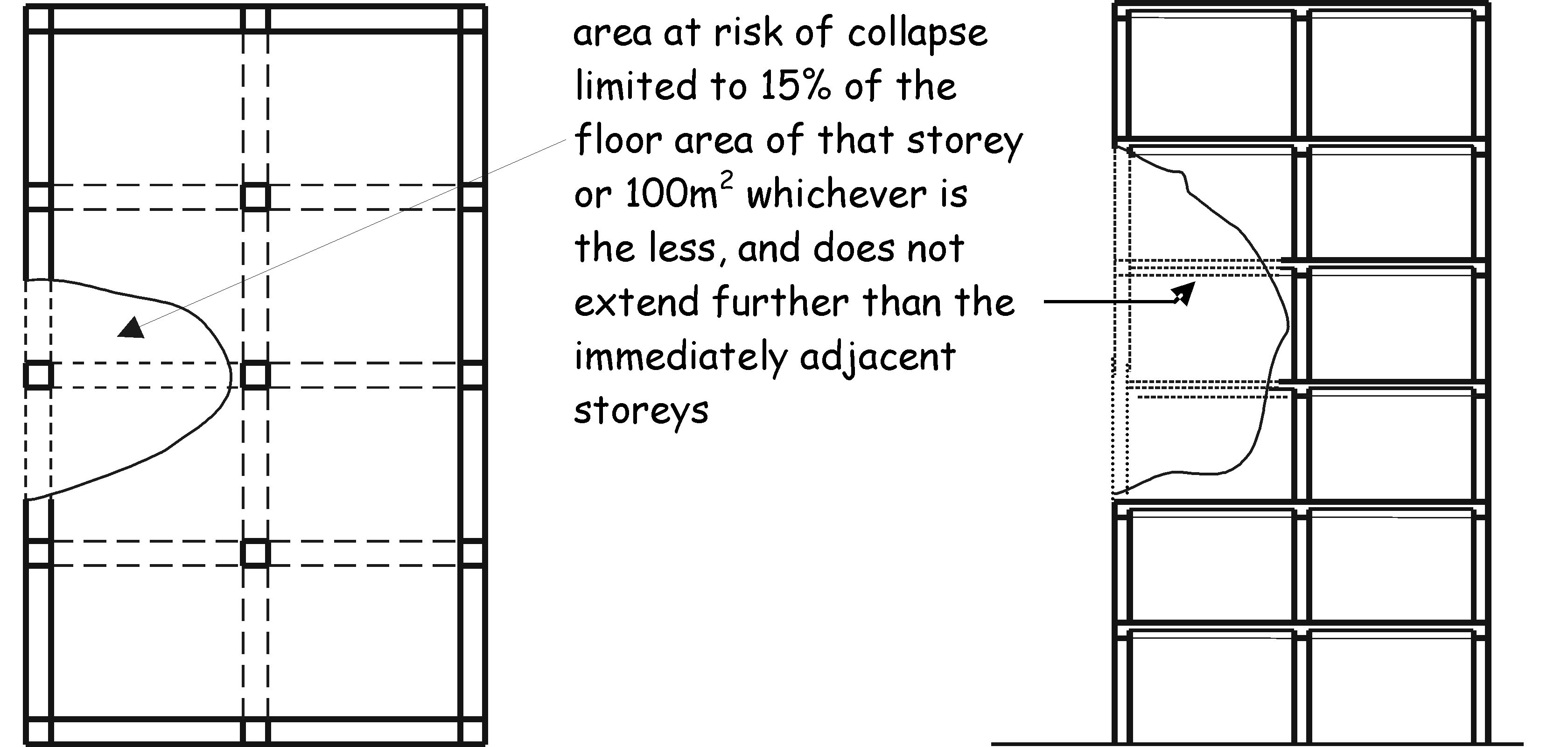
Risk Group 3 buildings - a systematic risk assessment of the building should be carried out, taking into account all the normal hazards that can be foreseen as far as possible together with any abnormal hazards.
Critical situations for design should be selected that reflect the conditions that can be foreseen as far as possible during the life of the building.
The structural form and concept and any protective measures should then be chosen and the detailed design of the structure and its elements undertaken in accordance with the recommendations in the codes and standards in clause 1.2.4.
1.2.4 Design and construct additional measures
The structural design and construction to take account of the additional measures including horizontal and vertical ties where appropriate and checking the integrity of the building following the notional removal of vertical members and the design of key elements, should be carried out in accordance with the design recommendations contained in Annex A of BS EN 1991-1-7:2006.
1.2.5 Other sources of guidance
More detailed information has been produced by organisations on disproportionate collapse as follows:
a.Technical Guidance Note – ‘The Building Regulations 2004 Edition – England and Wales Requirement A3 – Disproportionate Collapse’, National House Building Council (NHBC)
b.Technical Bulletin Number 3 ‘Design Guidance for Disproportionate Collapse’, UK Timber Frame Association
c.‘Masonry Design for Disproportionate Collapse Requirements under Regulation A3 of the Building Regulations (England & Wales)’, Brick Development Association
d.'Guidance on meeting the Robustness Requirements in Approved Document A', Steel Construction Institute
e.'How to design concrete buildings to satisfy disproportionate collapse requirements'. http://www.concretecentre.com/
The above guidance is based on England & Wales Regulation A3 and should be interpreted in relation to Standard 1.2. In particular, references to building classes should be risk groups and the building types and occupancy should be interpreted as the building types set out in the table to clause 1.2.2.
Annex 1.A Structural Design Standards
#Source page 21
1.A.0 Introduction
The British Standards Institution (BSI) agreement with the European Committee for Standardisation (CEN) obliges it to withdraw UK national standards after a harmonised European Standard with the same scope and field of application has been produced. BSI, in line with this commitment, will by 31 March 2010 replace the British Standards relating to loading and structural design with the European Standards and associated National Annexes listed in the tables below:
1.A.1 Structural Design Standards [1]
Table 1.2. Eurocode: Basis of structural design
| Eurocode: Basis of structural design | Corresponding BS to be withdrawn |
|---|---|
| BS EN 1990: 2002 Basis of structural design | |
| Note: Some sections of EN 1990 correspond with BS 5268-2, BS 5628-1, BS 5950-1 and BS 8110-1 and 2. BS 5400-1 which is not referred to in Section 1: Structure also has some content that corresponds to EN 1990. |
Table 1.3. Eurocode 1: Actions on structures
| Eurocode 1: Actions on structures | Corresponding BS to be withdrawn |
|---|---|
| BS EN 1991-1-1: 2002 Actions on structures. General actions. Densities, self-weight, imposed loads for buildings | BS 6399-1, BS 6399-3, BS 648 |
| BS EN 1991-1-2: 2002 Actions on structures. General actions. Actions on structures exposed to fire | |
| BS EN 1991-1-3: 2003 Actions on structures. General actions. Snow loads | BS 6399-3 |
| BS EN 1991-1-4: 2005 Actions on structures. General actions. Wind actions | BS 6399-2, BS 5400-2 |
| BS EN 1991-1-5: 2003 Actions on structures. General actions. Thermal actions Note: Some sections of EN 1991-1-5 relating to bridges correspond to BS 5400-2 | |
| BS EN 1991-1-6: 2005 Actions on structures. General actions. Actions during execution | |
| BS EN 1991-1-7: 2006 Actions on structures. General actions. Accidental actions | Minimal guidance in BS 6399-1. Some sections of EN 1991-1-7 correspond with BS 6399-1, BS 5268-1, BS 5628-1, BS 5950-1, BS 8110-1 and 2 and BS 5400-3 |
| BS EN 1991-2: 2003 Actions on structures. Traffic loads on bridges | BS 5400-2 |
| BS EN 1991-3: 2006 Actions on structures. Actions induced by cranes and machines | |
| BS EN 1991-4: 2006 Actions on structures. Silos and tanks |
Table 1.4. Eurocode 2: Design of concrete structures
| Eurocode 2: Design of concrete structures | Corresponding BS to be withdrawn |
|---|---|
| BS EN 1992-1-1: 2004 Design of concrete structures. General rules and rules for buildings | BS 8110-1, BS 8110-2, BS 8110-3 |
| BS EN 1992-1-2: 2004 Design of concrete structures. General rules. Structural fire design | BS 8110-1, BS 8110-2 |
| BS EN 1992-2: 2005 Design of concrete structures. Concrete bridges. Design and detailing rules | BS 5400-4, BS 5400-7, BS 5400-8 |
| BS EN 1992-3: 2006 Design of concrete structures. Liquid retaining and containing structures | BS 8007 |
Table 1.5. Eurocode 3: Design of steel structures
| Eurocode 3: Design of steel structures | Corresponding BS to be withdrawn |
|---|---|
| BS EN 1993-1-1: 2005 Design of Steel structures. General rules and rules for buildings | BS 5950-1, BS 5400-3 |
| BS EN 1993-1-2: 2005 Design of steel structures. General rules. Structural fire design | BS 5950-8 |
| BS EN 1993-1-3: 2006 Design of steel structures. General rules. Supplementary rules for cold-formed members and sheeting | BS 5950-5, BS 5950-6, BS 5950-9 |
| BS EN 1993-1-4: 2006 Design of steel structures. General rules. Supplementary rules for stainless steels | |
| BS EN 1993-1-5: 2006 Design of steel structures. Plated structural elements | BS 5950-1, BS 5400-3 |
| BS EN 1993-1-6: 2007 Design of steel structures. General. Strength and stability of shell structures | |
| BS EN 1993-1-7: 2007 Design of steel structures. Plated structures subject to out of plane loading | |
| BS EN 1993-1-8: 2005 Design of steel structures. Design of joints | BS 5950-1 BS 4604-1, BS 4604-2, BS 5400-3 |
| BS EN 1993-1-9: 2005 Design of steel structures. Fatigue | BS 5950-1, BS 5400-10 |
| BS EN 1993-1-10: 2005 Design of steel structures. Material toughness and through-thickness properties | BS 5950-1, BS 5400-3 |
| BS EN 1993-1-11: 2006 Design of steel structures. Design of structures with tension components | |
| BS EN 1993-1-12: 2007 Design of steel structures. Additional rules for the extension of EN 1993 to steel grades S700 | BS 5950-1 |
| BS EN 1993-2: 2006 Design of steel structures. Steel bridges | BS 5400-3 |
| BS EN 1993-3-1: 2007 Design of steel structures. Towers, masts and chimneys. Towers and masts | BS 8100-1, BS 8100-2, BS 8100-3, BS 8100-4 |
| BS EN 1993-3-2: 2008 Design of steel structures. Towers, masts and chimneys. Chimneys | BS 4076 |
| BS EN 1993-4-1: 2007 Design of steel structures. Silos, tanks and pipelines. Silos | |
| BS EN 1993-4-2: 2007 Design of steel structures. Silos, tanks and pipelines. Tanks | |
| BS EN 1993-4-3: 2007 Design of steel structures. Silos, tanks and pipelines. Pipelines | |
| BS EN 1993-5: 2007 Design of steel structures. Piling | BS 5950-1 |
| BS EN 1993-6: 2007 Design of steel structures. Crane supporting structures | BS 5950-1, BS 2853 |
Table 1.6. Eurocode 4: Design of composite steel and concrete structures
| Eurocode 4: Design of composite steel and concrete structures | Corresponding BS to be withdrawn |
|---|---|
| BS EN 1994-1-1: 2004 Design of composite steel and concrete structures. General rules and rules for buildings | BS 5950-3.1, BS 5950-4 |
| BS EN 1994-1-2: 2005 Design of composite steel and concrete structures. General rules. Structural fire design | BS 5950-8 |
| BS EN 1994-2: 2005 Design of composite steel and concrete structures. General rules and rules for bridges | BS 5400-5 |
Table 1.7. Eurocode 5: Design of timber structures
| Eurocode 5: Design of timber structures | Corresponding BS to be withdrawn |
|---|---|
| BS EN 1995-1-1: 2004 Design of timber structures. General. Common rules and rules for buildings | BS 5268-2, BS 5268-3, BS 5268-6.1, BS 5268-6.2, BS 5268-7.1, BS 5268-7.2, BS 5268-7.3, BS 5268-7.4, BS 5268-7.5, BS 5268-7.6, BS 5268-7.7 |
| BS EN 1995-1-2: 2004 Design of timber structures. General. Structural fire design | BS 5268-4.1, BS 5268-4.2 |
| BS EN 1995-2: 2004 Design of timber structures. Bridges |
Table 1.8. Eurocode 6: Design of masonry structures
| Eurocode 6: Design of masonry structures | Corresponding BS to be withdrawn |
|---|---|
| BS EN 1996-1-1: 2005 Design of masonry structures. General rules for reinforced and unreinforced masonry structures | BS 5628-1, BS 5628-2 |
| BS EN 1996-1-2: 2005 Design of masonry structures. Structural fire design | BS 5628-3 |
| BS EN 1996-2: 2006 Design of masonry structures. Design considerations, selection of materials and execution of masonry | BS 5628-3 |
| BS EN 1996-3: 2006 Design of masonry structures. Simplified calculation methods for unreinforced masonry structures |
Table 1.9. Eurocode 7: Geotechnical design
| Eurocode 7: Geotechnical design | Corresponding BS to be withdrawn |
|---|---|
| BS EN 1997-1: 2004 Geotechnical design. General rules | BS 8002, BS 8004, BS 8006, BS 8081 |
| BS EN 1997-2: 2007 Geotechnical design. Ground investigation and testing |
Table 1.10. Eurocode 8: Design of structures for earthquake resistance
| Eurocode 8: Design of structures for earthquake resistance | Corresponding BS to be withdrawn |
|---|---|
| BS EN 1998-1: 2004 Design of structures for earthquake resistance. General rules. Seismic actions for buildings | |
| BS EN 1998-2: 2005+Amendment 1: 2009 Design of structures for earthquake resistance. Bridges | |
| BS EN 1998-3: 2005 Design of structures for earthquake resistance. Assessment and retrofitting of buildings | |
| BS EN 1998-4: 2006 Design of structures for earthquake resistance. Silos tanks and pipelines | |
| BS EN 1998-5: 2004 Design of structures for earthquake resistance. Foundations, retaining structures and geotechnical aspects | |
| BS EN 1998-6: 2005 Design of structures for earthquake resistance. Towers masts and chimneys |
Table 1.11. Eurocode 9: Design of aluminium structures
| Eurocode 9: Design of aluminium structures | Corresponding BS to be withdrawn [1] |
|---|---|
| BS EN 1999-1-1: 2007 Design of aluminium structures. General rules | BS 8118-1, BS 8118-2 |
| BS EN 1999-1-2: 2007 Design of aluminium structures. General. Structural fire design | |
| BS EN 1999-1-3: 2007 Design of aluminium structures. Additional rules for structures susceptible to fatigue | BS 8118-1 |
| BS EN 1999-1-4: 2007 Design of aluminium structures. Supplementary rules for trapezoidal sheeting | |
| BS EN 1999-1-5: 2007 Design of aluminium structures. Supplementary rules for shell structures | BS 8118-1 |
Additional Information. Note 1: Many of these standards are not directly, or are not currently referenced in Section 1: Structure. Some may not be applicable to Section 1 Structure such as, BS 5400 for bridges, or are applicable to other parts of the technical handbooks.
2.0 Introduction
#Source page 22
2.0.1 Background
Life safety is the paramount objective of fire safety. Non-domestic buildings should be designed and constructed in such a way that the risk of fire is reduced and if a fire does occur, there are measures in place to restrict the growth of fire and smoke to enable the occupants to escape safely and fire-fighters to deal with fire safely and effectively.
There are more than 3000 reported fires in non-domestic buildings every year in Scotland. The most common cause of accidental fires in non-domestic buildings is faulty appliances and leads, accounting for more than 21% of fires followed by misuse of equipment or appliances at around 11%. Statistics also show that around 39% of fires in non-domestic buildings are deliberately started. While the number of deaths from fires in non-domestic buildings is less than domestic buildings the potential for significant life loss and injuries is far greater. This is due to the large occupancy capacities that may be involved and the complexity of occupant behaviour including the potential for delay in occupant evacuation following the outbreak of fire.
In the event of an outbreak of fire, it is important that the occupants are warned as soon as possible. The guidance to Standard 2.11 provides recommendations for the installation of alarm and detection systems in buildings where people may be asleep or where there is a particularly high risk.
The standards and guidance in this section are designed to work together to provide a balanced approach to fire safety. The building elements, materials, components or other parts of the building identified in the guidance should follow the appropriate performance levels that are recommended throughout the guidance. However where a building element, material, component, or other part of a building is covered by more than one standard, the more demanding guidance should be followed.
2.0.2 Aims
The purpose of the guidance in Section 2 is to achieve the following objectives in the case of an outbreak of fire within the building:
•to protect life
•to assist the fire and rescue services, and
•to further the achievement of sustainable development.
Protection of life - it is important to recognise that the standards will not guarantee the life safety of all building occupants. Occupants in buildings do not normally perceive themselves to be at risk from fire and are not usually aware of the speed that fire can spread. The risk to occupants is greater if they are asleep during the outbreak of fire as they are likely to be roused more slowly. Occupants should be warned as soon as possible following the outbreak of fire and the guidance to Standard 2.11 provides recommendations for the installation of alarm and detection systems in non-domestic buildings.
Fire and rescue service - in some cases, occupants will not react quickly enough before being overcome by the effects of the fire and smoke and as a result, may require to be rescued by the fire and rescue service. For facilities to assist the fire and rescue service, see Standards 2.12 to 2.14.
Sustainability - the building regulations are primarily concerned with the protection of people from the dangers inherent in buildings, rather than protecting the owners of buildings from any economic loss which might occur. However following the guidance in the handbook will continue to embed active and passive fire protection systems within buildings which should reduce the likelyhood of the total destruction of the building following the outbreak of fire.
2.0.3 Scope
Guidance in this section may not be appropriate for the following buildings as they are rarely designed and constructed in Scotland:
•buildings with a storey at a height of more than 60m
•enclosed shopping centres with malls on 3 or more storeys, and
•air supported structures.
In such cases, the alternative approach as described in clause 2.0.7 should be followed.
In the case of a mixed use building containing non-domestic and domestic accommodation, reference should be made to the Technical Handbook for domestic buildings as well as the guidance contained in this Handbook.
2.0.4 Method of measurement
The rules of measurement in Section 0 of the Technical Handbook may not be appropriate for the guidance in Section 2 Fire. For example, to establish the height of the topmost storey for fire and rescue service facilities, the height should be measured from the fire and rescue service access level and not necessarily the lowest ground level. Therefore, methods of measurement unique to fire are described within the guidance under each of the relevant standards.
The following guidance on measurements are unique to Section 2 Fire of the Handbooks and where appropriate, should be read in conjunction with the measurements specified in schedule 4 to regulation 7 as set out in Section 0 General.
Plant storeys - for the purpose of measuring the height above ground to the top most storey of a building, roof-top plant areas and any top storeys consisting solely of plant rooms, should be excluded.
An openwork floor is a floor with an open mesh decking which allows smoke to pass through. It is common to construct multi-level openwork floors around high bay racking systems. In such cases, the total storey area should be taken to be the total area of all openwork floors within that storey, including the floor area taken up by the racking system. Therefore, each level should be measured independently to the innermost surface of the enclosing walls and then added together to give the total storey area.
The area of:
a.a compartment should be taken to be the total floor area of all storeys within that compartment
b.an enclosed shopping centre with a mall should be taken to be the total floor area of all storeys within that enclosed shopping centre
c.a storey should be taken to be the total area of all floors within that storey, including the floor area of any gallery or openwork floor.
2.0.5 Latest changes
The key changes that have been made to the standards and guidance since 1 October 2013.
•Standard 2.5 - guidance amended to allow smaller luminaires (with TPb diffusers) to be arranged closer together.
2.0.6 Explanation of terms
Buildings accessible to the general public is intended to include buildings where members of the public can enter during normal opening hours and are allowed to access all parts of the building, other than those parts restricted to staff only.
Protected routes of escape - throughout the document there are references to protected routes of escape these include: escape routes in a central core, fire and smoke control in corridors, flat roofs, access decks, galleries with rooms enclosed below, openings in floors, places of special fire risk, protected lobbies, protected zones, rooms, toilets and washrooms in protected zones, external escape stairs, escape stairs in basements and auditoria. This list is not exhaustive and is not intended to cover all parts of a building providing protected routes of escape. For example, compartment walls and compartment floors also protect routes of escape but are covered by the guidance to Standard 2.1.
External areas - a roof, an external balcony, or an enclosed courtyard open to the external air, where the area is more than 8m2 and to which there is access for a purpose other than maintenance, should be regarded as a room.
Circulation areas in non-domestic buildings include unprotected zones or areas in a room or space which provide access to an exit and may be permanently demarcated from any space intended for human occupation.
2.0.7 Alternative approaches
Fire safety engineering can provide an alternative approach to the fire safety measures contained in this Technical Handbook. It may be the only practical way to achieve a satisfactory level of fire safety in some large and complex buildings, and in buildings containing different uses such as airport terminals.
Fire safety engineering may also be suitable for solving a problem with any aspect of the design which otherwise follows the guidance in this Handbook. Alternative fire safety measures include for example, the use of automatic fire detection, suppression and ventilation systems in conjunction with passive fire protection. It is reasonable to demonstrate compliance with the functional standards by alternative means and in such cases, the verifier and the fire authority should be consulted early in the design process.
Not all cases of variance from the guidance will require the appointment of a fire engineer. Reference could be made to ‘A simplified approach to alternative fire safety strategies’ Scottish Government (2010).
Existing buildings - it may be appropriate to vary the guidance contained in this Handbook when assessing the guidance against the constraints in existing buildings or in buildings which are listed in terms of their architectural or historic interest. In such cases, it would be appropriate to take into account a range of fire safety features, some of which are dealt with in this Handbook and some of which are not addressed in any detail. For more detailed information, guidance is contained in the ‘Guide for Practitioners 6 – Conversion of traditional buildings’ (Historic Scotland) http://www.historic-scotland.gov.uk/.
Fire engineering designs can be complex and many require extensive use of engineering judgement. The following documents are cited to ensure that the guidance given encompasses best practice worldwide:
•BS 7974: 2001 Application of fire safety engineering principles to the design of buildings, or
•International Fire Engineering Guidelines, 2005 (IFEG).
The use of either document assumes that those carrying out or assessing a fire engineering approach have sufficient technical training, knowledge and experience to understand fully the risks involved.
The objectives of any fire safety strategy should be established first and designers and verifiers should be aware of the importance of the design assumptions. For example, the strategy should include an assessment of the system reliability. This will help to ensure that the fire safety objectives have been met.
Responsible person - it is important that owners/responsible person understand that the fire safety measures installed in a building need to be maintained and tested over the life time of the building so that they will operate effectively. BS 7974 and IFEG assume that all aspects of the fire engineering strategy are capable of being maintained and deployed over the lifetime of the building. If for example, alterations are found to be necessary due to changes to the building layout, the original strategy may need to be re-evaluated to ensure the fire safety provisions have not been compromised. For this reason, the fire strategy should preferably support any fire safety risk assessment required under Part 3 of the Fire (Scotland) Act 2005, as amended.
Fire safety engineering involves the use of scientific based calculations and/or statistical information to demonstrate an adequate level of safety for a specific building, structure or installation. In this regard the fire safety strategy is based on performance rather than prescription. Therefore, fire safety engineering is about the need to identify the fire hazard, assess the fire risks, understand the consequences and to offer fire safety strategies and designs to show how the objectives have been met. The ‘tools’ that support fire engineering can include calculation methods, which are used to demonstrate that under a worst reasonable case, tenable conditions are maintained during the evacuation period. For example, a smoke exhaust fan in a smoke reservoir within an atrium space fails to operate but the smoke layer height continues to be maintained by the activation of a stand-by fan.
It is recognised that fire engineering is still a rapidly developing field and as such does not have the standardised codes for approaching and solving problems compared to other engineering disciplines. The documents identified above aim to provide a structured framework for assessing the interaction between, buildings, people and fire, and to facilitate innovation in design without compromising safety. They provide information on how to undertake a detailed analysis of specific aspects of fire safety engineering in buildings.
In practice, both frameworks provide a flexible but formalised engineering approach to fire safety which can be applied to new or existing buildings to show that the functional standards have been met.
BS 7974: 2001 Application of fire safety engineering principles to the design of buildings is supported by 8 published documents:
•Part 0: Guide to the design framework and fire safety engineering procedures
•Part 1: Initiation and development of fire within the enclosure of origin
•Part 2: Spread of smoke and toxic gases within and beyond the enclosure of origin
•Part 3: Structural response and fire spread beyond the enclosure of origin
•Part 4: Detection of fire and actuation of fire protection systems
•Part 5: Fire service intervention
•Part 6: Human factors: Life safety strategies – Occupant evacuation, behaviour and condition, and
•Part 7: Probabilistic risk assessment.
International Fire Engineering Guidelines (IFEG) have been developed for use in the fire engineering design and approval of buildings. The objectives of the guidelines are to provide:
•international fire engineering guidelines
•a link between the regulatory system and fire engineering
•guidance for the process of engineering, and
•guidance on available methodologies.
The IFEG sub-systems bear a very close resemblance to the subsystems used in BS: 7974 and are set out below:
•fire initiation and development and control
•smoke development and spread and control
•fire spread and impact and control
•fire detection, warning and suppression
•occupant evacuation and control, and
•fire services intervention.
Clause 1.3.2 of IFEG states that “Typically, each building project is unique and similarly, each fire engineering evaluation is unique". It is not sensible, therefore, to set down detailed guidance on how the fire safety analysis should be undertaken. Instead, it is the responsibility of the fire engineer to plan the analysis for the particular project, based on the decisions taken during the preparation of the fire engineering brief.
Places of lawful detention for example prisons, secure accommodation and mental health premises, present particular problems owing to the obvious difficulties of providing both the level of security required and effective means of evacuation in the event of fire. Due to the constraints this can place on the design it may be necessary to vary from the guidance contained in this section of the Technical Handbook. In some cases it may be necessary to use fire safety engineering as part of such an alternative approach having evaluated the full range of fire safety features proposed to control the risk and the potential consequences of a fire.
2.0.8 Relevant legislation
It is important to be aware that there is other legislation, apart from building regulations, imposing requirements for means of escape in case of fire and other fire safety measures. It is therefore recommended that consultation with those responsible for such legislation takes place before the application for building warrant is finalised. Any necessary fire safety measures requiring building work can then be included in the application.
Fire (Scotland) Act 2005, Part 3 as amended introduced a fire safety regime which applies to non-domestic buildings. The regime does not generally apply to domestic buildings but may apply where staff are employed or members of the general public have access e.g. a dental surgery within a dwelling. The regime will also apply to domestic buildings which are licensed as Houses in Multiple Occupation and to some domestic buildings where certain care services are provided. Those domestic premises covered by Part 3 of the 2005 Act are defined in section 78 of the Act.
Persons with obligations under the Act are required to carry out a fire safety risk assessment which may require additional fire safety precautions to reduce the risk to life in case of fire. For example, measures to reduce the risk and spread of fire, means of escape, fire-fighting equipment, fire detection and warning, instruction and training. Other measures are prescribed by regulation. The fire safety risk assessment should be kept under continuous review.
There is (sector specific) guidance for various building uses on how to comply with Part 3 of the Act, such as guides for premises providing sleeping accommodation, places of entertainment and assembly, healthcare premises and care homes. This guidance can be found using the link to the firelaw website (www.infoscotland.com/firelaw).
In many premises, existing fire safety measures have been incorporated in accordance with building regulations however it is possible for a higher standard to be applied as a consequence of a fire safety risk assessment.
Section 71 of the 2005 Act makes it clear that terms, conditions or restrictions in licences, including statutory certification or registration schemes, are to have no effect if they relate to fire safety requirements or prohibitions which are or could be imposed under Part 3 of the 2005 Act.
The Fire Safety (Scotland) Regulations 2006 made under the Fire (Scotland) Act 2005 contain provisions which are part of the fire safety regime. These regulations must be considered along with Part 3 of the 2005 Act. The regulations contain further requirements in respect of fire safety risk assessment and obligations of duty holders.
Section 70 of the Fire (Scotland) Act 2005 restricts the application of Part 1 of the Health and Safety at Work Act 1974 and any regulations or orders made under it in relation to general fire safety. There are exceptions; firstly where a single enforcing authority enforces both pieces of legislation and secondly, in respect of sites where the Control of Major Accident Hazards Regulations 1999 (COMAH) apply.
The Management of Health and Safety at Work Regulations 1999 require all employers to assess the risks to workers and any others who may be affected by their work or business. The objective is to identify preventative and protective measures and implement corrective action as appropriate. However in general, these regulations do not apply to general fire safety by virtue of the restriction in section 70 of the Fire (Scotland) 2005 Act.
The Health and Safety (Safety Signs and Signals) Regulations 1996 impose requirements in relation to fire exit and directional signs. In addition, the Fire (Scotland) Regulations 2006 requires emergency routes and exits to be indicated by signs. Advice on fire safety signs is given in the HSE publication, ‘Safety signs and signals: Guidance on Regulations – The Health and Safety (Safety Signs and Signals) Regulations 1996’. Guidance is also available in BS 5499: Part 1: 2002, and BS 5499: Part 4: 2000 on graphical symbols, fire safety signs and escape route signing.
The Construction (Design and Management) Regulations 2007 is intended to protect people working in construction and others who may be affected by their activities. The regulations require the systematic management of projects from concept to completion and throughout the life cycle of the structure, including eventual demolition. The CDM Regulations require designers and those who control or carry out construction work to identify hazards associated with their designs or work (including risk from fire) and plan to eliminate, reduce or control the risks.
Dangerous Substances and Explosive Atmospheres Regulations 2002 require the risks from substances with flammable, explosive or oxidising properties to be properly controlled. This can include particular requirements in respect of design and construction in which substances are present or in the vicinity. The regulations are enforced by the HSE, or for certain types of premises, the local authority. In general, these regulations do not apply to general fire safety as a result of similar provisions being imposed by the Fire Safety (Scotland) Regulations 2006.
When designing or verifying sports grounds, it is appropriate to use the guide to Safety at Sports Grounds http://www.culture.gov.uk/. The guide has no statutory force but many of its recommendations will be given force of law at individual grounds by their inclusion in safety certificates issued under the Safety of Sports Grounds Act 1975 or the Fire Safety and Safety of Places of Sport Act 1987.
The Safety of Sports Grounds Act 1975 is amended by Article 7 of the Fire (Scotland) Act 2005 (Consequential Modifications and Savings) Order 2006 so that a condition of a safety certificate for a sports ground may not require a person to contravene Part 3 of the 2005 Act or regulations made under it and requires the local authority to amend such a certificate if it would have that effect.
The Fire Safety and Places of Sports Act 1987 is amended by Article 13 of the Fire (Scotland) Act 2005 (Consequential Modifications and Savings) Order 2006 so that a condition of a safety certificate for a regulated stand may not require a person to contravene Part 3 of the 2005 Act or regulations made under it and requires the local authority to amend such a certificate if it would have that effect.
The Civic Government (Scotland) Act 1982 contains provisions for public entertainment licences. Similarly to liquor licences, the appropriate bodies are consulted before a licence is granted. The Act has been amended by the Fire (Scotland) Act 2005 (Consequential Modifications and Savings) Order 2006 to prevent fire safety conditions being imposed where Part 3 of the Fire (Scotland) Act 2005, as amended applies.
The domestic Technical Handbook should be used for Houses in Multiple Occupation (HMOs) that are dwellings and the non-domestic Technical Handbook should be used for all other HMOs. It should be noted that HMOs may also require to be licensed under the Civic Government (Scotland) Act 1982 (Licence of House in Multiple Occupation) - Order 2000 as amended. To be classified as a house in multiple occupation, the accommodation must be the only or principal residence of 3 or more people from different families. In relation to fire safety aspects, HMOs which require a licence are also subject to Part 3 of the Fire (Scotland) Act 2005, as amended and guidance is available on the firelaw website to assist those with responsibilities for licensed HMOs understand and comply with fire safety legislation http://www.firelawscotland.org/.
The Care Inspectorate is responsible for regulating a diverse range of care services some of which are delivered in non-domestic buildings (e.g. care homes, nurseries, independent hospitals, hospices, residential schools and secure accommodation) and some in domestic buildings (e.g. childminding, supported accommodation and adult placement services). The services are inspected by the Inspectorate against national care standards issued by Scottish Ministers some of which include physical standards for the premises. The Inspectorate consults with the fire authority on fire safety matters as part of the care service registration process. Where the applicant for a warrant intends to use or provide such a service, they should consult the Inspectorate for advice.
2.0.9 Annexes
2.A - Additional guidance for residential care buildings
2.B - Additional guidance for hospitals
2.C - Additional guidance for enclosed shopping centres
Certain types of buildings pose particular risks and require particular solutions. Additional guidance for three specific building types are grouped in three annexes; residential care buildings in annex 2.A; hospitals in annex 2.B and enclosed shopping centres in annex 2.C. Where an enclosed shopping centre has a mall on 3 storeys or more, the alternative approach described in clause 2.0.7 should be used.
The intention is to help designers and verifiers find the information they require quickly when designing or vetting such buildings. However it is important to remember that the guidance in the annexes is in addition and supplementary to the guidance to Standard 2.1 to 2.15.
Annex 2.D: Resistance to fire
Resistance to fire is expressed in terms of fire resistance duration and reference throughout this document to a short, medium or long fire resistance duration, are explained in annex 2.D. The performance levels include properties such as loadbearing capacity, integrity and insulation.
Annex 2.E: Reaction to fire
Construction products are expressed as non-combustible low, medium, high or very high risk and explained in annex 2.E. The performance levels include properties such as the ease of ignition and the rate at which the product gives off heat when burning. This document does not give detailed guidance on other properties such as the generation of smoke, fumes and flaming droplets/particles.
Annex 2.F: Vulnerability of roof coverings
Roof coverings are expressed in terms of low, medium or high vulnerability and explained in annex 2.F. The performance levels relate to the capability of a roof to resist penetration from fire and flame spread when the external surface is exposed to radiation and flames.
2.0.10 Independent schemes of certification and accreditation
Certification - Scottish Ministers can, under Section 7 of the Building (Scotland) Act 2003, approve schemes for the certification of design or construction for compliance with the mandatory functional standards. Such schemes are approved on the basis that the procedures adopted by the scheme will take account of the need to co-ordinate the work of various designers and specialist contractors. Individuals approved to provide certification services under the scheme are assessed to ensure that they have the qualifications, skills and experience required to certify compliance for the work covered by the scope of the scheme. Checking procedures adopted by Approved Certifiers will deliver design or installation reliability in accordance with legislation.
Third party accreditation - Since the performance of a system, product, component or structure is dependent upon satisfactory site installation, testing and maintenance, independent schemes of certification and accreditation of installers and maintenance firms of such will provide confidence in the appropriate standard of workmanship being provided.
Confidence that the required level of performance can be achieved will be demonstrated by the use of a system, material, product or structure which is provided under the arrangements of a product conformity certification scheme and an accreditation of installers scheme. Third party accredited product conformity certification schemes not only provide a means of identifying materials and designs of systems, products or structures which have demonstrated that they have the requisite performance in fire, but additionally provide confidence that the systems, materials, products or structures actually supplied are provided to the same specification or design as that tested/assessed.
Third party accreditation of installers of systems, materials, products or structures provides a means of ensuring that installations have been conducted by knowledgeable contractors to appropriate standards, thereby increasing the reliability of the anticipated performance in fire.
Local authority verifiers may accept the certification of products, components, materials or structures under such schemes as evidence of compliance with the relevant standard. Similarly, local authority verifiers may accept the certification of the installation or maintenance of products, components, materials or structures under such schemes as evidence of compliance with the relevant standard. Nonetheless, a local authority verifier may wish to establish, in advance of the work, that any such scheme is adequate for the purposes of the Building Regulations.
Many certification bodies which approve such schemes are accredited by UKAS.
2.1 Compartmentation
#Source page 23
Mandatory Standard
| Standard 2.1 Every building must be designed and constructed in such a way that in the event of an outbreak of fire within the building, fire and smoke are inhibited from spreading beyond the compartment of origin until any occupants have had the time to leave that compartment and any fire containment measures have been initiated. Limitation: This standard does not apply to domestic buildings. |
2.1.0 Introduction
The aim of compartmentation is to inhibit rapid fire spread within the building by reducing the fuel available in the initial stages of a fire. The intention is to limit the severity of the fire which in turn should help the occupants to evacuate the building and assist fire and rescue service personnel with fire-fighting and rescue operations. This is achieved by dividing the building into a series of fire tight boxes termed compartments which will form a barrier to the products of combustion; smoke, heat and toxic gases.
The use of a building, the height of the topmost storey, the inclusion of automatic fire suppression systems and the fire resistance duration will determine the maximum area of the compartments within a building. Designers may also choose to construct compartments based on client and aesthetic needs. For example, the designer may use compartmentation to classify the building into different uses or to reduce travel distances (see clause 2.9.3).
Common guidance - the guidance in clauses 2.1.14 (Openings and service penetrations), 2.1.15 (Junctions) and 2.1.16 (Fire resisting ceilings) is common, not only to compartmentation and sub-compartmentation, but also to the relevant guidance in Standards 2.2 separation, 2.4 cavities, 2.9 escape and the relevant guidance contained in the annexes. To avoid duplication, these clauses are referred to throughout the Handbook and the reader is prompted to return to these common clauses whenever it is considered appropriate.
Due to the special fire precautions within residential care buildings, hospitals and enclosed shopping centres, additional guidance is grouped in the annexes. The intention is to help designers and verifiers find the information they require quickly when designing or vetting such buildings. However it is important to remember that the guidance in the annexes is in addition and supplementary to the guidance to Standards 2.1 to 2.15. For additional guidance on:
•residential care buildings, see annex 2.A
•hospitals, see annex 2.B
•enclosed shopping centres, see annex 2.C.
Conversions - in the case of conversions, as specified in regulation 4, the building as converted shall meet the requirement of this standard (regulation 12, schedule 6).
2.1.1 Maximum compartment areas
A building, or part of a building, with a total storey area more than the limits given in the tables below should be sub-divided by compartment walls and, where appropriate, compartment floors. The minimum fire resistance duration (see annex 2.D) can be obtained from the tables below (see also clause 2.1.4).
In most cases, a single-storey building poses less of a life risk to the occupants or to fire and rescue service personnel than a multi-storey building, therefore a greater compartment size can be constructed.
Table 2.1. Single-storey buildings and compartmentation between single-storey and multi- storey buildings where appropriate
| Building Use | Maximum total area of any compartment (m2) | Minimum fire resistance duration for compartmentation (if any) |
|---|---|---|
| Assembly building | 6,000 [1] | Long |
| Entertainment building | 2,000 [1] | Medium |
| Factory (Class 1) | 33,000 [1] | Long [3] |
| Factory (Class 2) | 93,000 [1] | Long [3] |
| Office | 4,000 [1] | Medium |
| Open sided car park | Unlimited | Not relevant |
| Residential care building, hospital | 1,500 | Medium |
| Residential building (other than a residential care building and hospital) | 2,000 | Medium |
| Shop | 2,000 [2] | Long |
| Storage building (Class 1) | 1,000 [1] | Long |
| Storage building (Class 2) | 14,000 [1] | Long [3] |
Additional information:
1.Areas may be doubled where there is an automatic fire suppression system (see clause 2.1.2).
2.Unlimited provided there is an automatic fire suppression system (see clause 2.1.2).
3.A medium fire resistance duration compartment wall or compartment floor may be provided between the single-storey part and the multi-storey part provided the multi-storey part does not exceed the limitations for medium fire resistance duration in the following table covering multi-storey buildings (see also clause 2.1.4).
Table 2.2. Multi-storey buildings
| Building Use | Maximum total area of any compartment (m2) | Maximum area of an individual storey within a compartment (m2) | Minimum fire resistance duration for compartmentation and elements of structure (see Standard 2.3) where appropriate | |||
|---|---|---|---|---|---|---|
| Basements | The topmost storey of a building is at a height of not more than 7.5m above ground | The topmost storey of a building is at a height of not more than 18m above ground | The topmost storey of a building is at a height of more than 18m above ground | |||
| Assembly building | 1,500 [1] | 1,500 [1] | Medium | Short | Medium | Long [2] |
| 3,000 [1] | 3,000 [1] | Medium | Medium | Medium | Long [2] | |
| 6,000 [1] | 3,000 [1] | Long | Long | Long | Long | |
| Entertainment building | 1,000 [1] | 1,000 [1] | Medium | Short | Medium | Long [2] |
| 2,000 [1] | 2,000 [1] | Medium | Medium | Medium | Long [2] | |
| 4,000 [1] | 2,000 [1] | Long | Long | Long | Long | |
| Factory (Class 1) | 500 [1] | 500 [1] | Medium | Medium | Medium | Long [2] |
| 6,000 [1] | 3,000 [1] | Long | Long | Long | Long | |
| Factory (Class 2) | 2,000 [1] | 2,000 [1] | Medium [4] | Medium [4] | Medium [4] | Medium [4] |
| 15,000 [1] | 7,500 [1] | Long | Long | Long | Long | |
| Office | 2,000 [1] | 2,000 [1] | Medium [4] | Short | Medium [4] | Long [2] |
| 4,000 [1] | 4,000 [1] | Medium [4] | Medium [4] | Medium [4] | Long [2] | |
| 8,000 [1] | 4,000 [1] | Long | Long | Long | Long | |
| Open sided car park | Unlimited | Unlimited | Medium | Short | Short | Medium |
| Residential care building, hospital | 1,500 | 1,500 | Medium | Medium | Medium | Long [2] |
| Residential building (other than a residential care building and hospital) | 1,000 | 1,000 | Medium | Short | Medium | Long [2] |
| 2,000 | 2,000 | Medium | Medium | Medium | Long [2] | |
| Shop | 500 [1] | 500 [1] | Medium [4] | Short | Medium [4] | Long [2] |
| 1,000 [1] | 1,000 [1] | Medium [4] | Medium [4] | Medium [4] | Long [2] | |
| 2,000 [3] | 1,000 [3] | Long | Long | Long | Long | |
| Storage building (Class 1) | 200 [1] | 200 [1] | Medium | Medium | Medium | Long [2] |
| 1,000 [1] | 500 [1] | Long | Long | Long | Long | |
| Storage building (Class 2) | 500 [1] | 500 [1] | Medium [4] | Medium [4] | Medium [4] | Medium [4] |
| 5,000 [1] | 2,500 [1] | Long | Long | Long | Long |
Additional information:
1.Areas may be doubled where there is an automatic fire suppression system (see clause 2.1.2).
2.Medium fire resistance duration for compartment walls.
3.Unlimited provided there is an automatic fire suppression system (see clause 2.1.2).
4.See buildings with different uses (clause 2.1.4).
2.1.2 Automatic fire suppression
Where it is intended to install automatic fire suppression systems, guidance can be obtained in the following publications:
•LPC Rules for Automatic Sprinkler Installations 2009, Incorporating BS EN 12845
•BS 5306: Part 4: 2001 for carbon dioxide systems
•BS 5306: Part 6: Section 6.1: 1988 for low expansion foam systems
•BS EN 12416-2: 2001 for powder systems.
2.1.3 Smoke and heat exhaust ventilation systems
Enclosed shopping centres - a smoke and heat exhaust ventilation system (SHEVS) should be installed in the mall of an enclosed shopping centre and in shops with a storey area more than 1,300m2 to prevent cool smoke from entering the mall. Guidance on SHEVS is provided in clause 2.C.1 of annex 2.C.
Similarly, large shops (other than in enclosed shopping centres), with a compartment area more than 5,600m2 should also be provided with SHEVS. Whilst annex 2.C relates to enclosed shopping centres, the guidance in clause 2.C.1 of annex 2.C may also be used for large shops.
2.1.4 Buildings with different uses
Buildings with different uses should be divided by compartment walls and compartment floors. However compartmentation need not be provided if the overall building attains the highest of the performance levels described in the guidance to Standards 2.1, 2.3 and 2.6. The intention is to allow design flexibility without reducing the risk to life safety. This is done by removing the need for compartmentation in a building or parts of a building where the overall building follows the more demanding guidance. For example, a compartment wall between a production area in a factory and part of the building used for storage need not be provided where an assessment of the overall building has been carried out for both uses and:
•the limits for compartmentation have not been exceeded (see clause 2.1.1), and
•the most demanding fire resistance duration of the element of structure has been followed (see clause 2.3.1), and
•the most severe minimum distance to the relevant boundary has been followed (see guidance to Standard 2.6).
However certain buildings are considered to present a lower level of risk to life safety and as a result, are given special consideration even where compartmentation between different uses is necessary. The buildings referred to are offices, shops, Factory (Class 2) or storage building (Class 2). Where the affected parts of the building are in the same occupation (see clause 2.2.2), short fire resistance duration is sufficient in lieu of medium fire resistance duration provided an automatic fire suppression system (see clause 2.1.2) is installed on both sides of the compartment wall, or on the storeys above and below the compartment floor where appropriate.
2.1.5 Residential buildings
In a residential building, every upper storey and every basement storey should form a separate compartment.
2.1.6 High rise buildings
Every floor at a storey height of more than 18m above the ground should be a compartment floor.
2.1.7 Basements
Where a building has a basement storey, the floor of the ground storey should be a compartment floor. However where the building comprises one basement storey and not more than 2 other storeys, and no storey has an area more than 280m2, a compartment floor need not be provided.
Where a building has a basement storey at a depth of more than 10m, every basement storey should form a separate compartment.
2.1.8 Places of special fire risk
Paint spraying - a place of special fire risk should be enclosed by compartment walls with a medium fire resistance duration. However this does not apply to a paint spray booth or to a room where cellulose or other flammable liquid spray is used, having a floor area not more than 100m2, constructed of prefabricated factory-made panels and is constructed in accordance with the recommendations in the Health and Safety Executive Guidance Note PM25 ‘Vehicle finishing units fire and explosion hazards’.
Where a place of special fire risk contains any appliance or equipment using hazardous liquid, any opening in a wall or floor dividing it from the remainder of the building should be constructed in such a manner that, in the event of any liquid spillage, the room will contain all the liquid in the appliance or equipment, plus 10%. See section 3, Environment for guidance on catch pits (bunds) for the storage of oil within a building.
2.1.9 Fire-fighting shafts
A fire-fighting shaft is an enclosure protected from fire in adjoining accommodation and contains an escape stair, a fire-fighting lobby at every storey at which the fire-fighting stair can be entered from the accommodation. The stair may also contain a fire-fighting lift together with its machine room (see clause 2.14.4).
These shafts are used in high buildings, deep buildings and in certain shops or storage buildings to assist fire and rescue service personnel to carry out fire-fighting and rescue operations.
The enclosing structure of a fire-fighting shaft should have a long fire resistance duration. However where the elements of structure in a building have a medium fire resistance duration, then the fire-fighting shaft need only have a medium fire resistance duration. A self-closing fire door in the enclosing structure of a fire-fighting shaft need only attain a medium fire resistance duration (see diagram to clause 2.14.3).
2.1.10 Smoke venting shafts
A smoke venting shaft should be enclosed by compartment walls with a medium fire resistance duration, other than at the smoke inlets and smoke outlets to the shaft.
2.1.11 Lift wells
A lift well should be enclosed by compartment walls with at least medium fire resistance duration and, where the lift well is not the full height of the building, a compartment floor with a medium fire resistance duration (see also capping systems in clause 2.1.15). Where a lift is installed, the landing controls and lift car controls should be of a type that do not operate on heat or pressure resulting from a fire.
A platform lift following the guidance in BS 6440: 1999 (see Section 4, Safety), need not be enclosed by compartment walls or compartment floors.
2.1.12 Combustibility
A compartment wall or compartment floor can be constructed of combustible materials having a low, medium, high or very high risk (see annex 2.E) provided the compartment wall or compartment floor has the appropriate fire resistance duration. However compartment walls and compartment floors in hospitals (see annex 2.B), should be constructed from materials which are non-combustible.
2.1.13 Supporting structure
Where an element of structure provides support to a compartment wall or compartment floor which attracts a higher fire resistance duration, the supporting element of structure should have at least the same period of fire resistance.
2.1.14 Openings and service penetrations
General
Compartment walls and compartment floors (including a fire resisting ceiling) are intended to prevent fire passing from one compartment to another. Openings and service penetrations through these walls or floors can compromise their effectiveness and should be kept to a minimum. The solum and roof space should not be forgotten. Openings and service penetrations should be carefully detailed and constructed to resist fire. This can be achieved by following the guidance below.
A self-closing fire door with the same fire resistance duration as the compartment wall should be installed in accordance with the recommendations in the Code of Practice, ‘Hardware for Fire and Escape Doors’ Issue 2, June 2006, published by the Door and Hardware Federation and the Guild of Architectural Ironmongers.
In some instances a self-closing fire door with a reduced fire resistance duration may be installed. For example, a self-closing fire door with a medium fire resistance duration may be installed in the enclosing structure of a fire-fighting shaft with a long fire resistance duration (see clause 2.1.9).
A lockable door to a cupboard or service duct where the cupboard or the service duct have a floor area not more than 3m2, need not be self-closing.
Self-closing fire doors can be fitted with hold open devices as specified in BS 5839: Part 3: 1988 provided the door is not an emergency door, a protected door serving the only escape stair in the building (or the only escape stair serving part of the building) or a protected door serving a fire-fighting shaft.
It is important that hold open devices deactivate on operation of the fire alarm therefore some buildings will need automatic fire detection to be installed. Electrically operated hold open devices should therefore deactivate on operation of:
•an automatic fire alarm system designed and installed in accordance with BS 5839: Part 1: 2002 (Category L5) determined on the basis of a risk assessment (see clauses 2.0.8), and
•any loss of power to the hold open device, apparatus or switch, and
•a manually operated switch fitted in a position at the door.
An example of a Category L5 fire alarm system could incorporate only 2 smoke detectors, one installed on each side of the door and positioned at least 500mm and not more than 3m from the door.
As an alternative to the above hold open device, an acoustically activated and/or radio activated door release mechanism and floor plate complying with BS EN 1155: 1997 may be installed on a risk assessment basis (see clause 2.0.8). Additional guidance is contained in BS 7273: Part 4: 2007.
In addition, this type of hold open device is not suitable for use in the following circumstances where:
•the door is an emergency door, or protected door serving the only escape stair in the building (or the only escape stair serving part of the building) or a protected door serving a fire-fighting shaft, or
•a Category M fire alarm system as defined in BS 5839: Part 1: 2002 is installed in the building, or
•the initial fire alarm warning signal is intended to alert staff only.
Additional guidance on the siting and coverage of fire detectors is contained in BS 5839: Part 1: 2002.
Automatically motorised fire shutters - should not be installed in the enclosing structure of a protected zone (see also clauses 2.9.15 and 2.9.27). However they may be used for the protection of service openings and ventilation ducts. Automatic motorised fire shutters should be fitted with audible and visual warning devices that operate on fire detection prior to activation of the fire shutter. However this is only necessary where there is a risk of people moving under the shutter in the event of an outbreak of fire within the building.
The visual warning devices should be fitted on both sides of the opening where the movement of people below the shutter is possible from both directions. Sensors should also be fitted that, when activated, temporarily halt the activation of the shutter. Automatic fire shutters should not be activated by a fire alarm signal from a remote location or out-with the fire alarm zone.
Fire shutter in compartment walls - a fire shutter which is not motorised may be fitted in a compartment wall provided the shutter has the same fire resistance duration as the compartment wall (see table to annex 2.D). Since a shutter activated by a fusible link or other heat sensitive device is not considered to be a threat to the occupants, warning devices need not be fitted.
Fire shutter in compartment floors - where an opening in a compartment floor contains a stair (but not an escape stair) and not more than 2 escalators:
•a horizontal fire shutter may be installed which maintains the fire resistance duration of the compartment floor and is activated by a fusible link or other heat-sensitive device positioned to detect fire in the lower compartment, or
•vertical fire shutters may be installed at each floor level (other than the topmost storey) which maintains the fire resistance duration of the compartment floor and are activated by smoke detection positioned to detect smoke in the lower compartment.
Where an escalator passes through the opening, it should come to a controlled halt before the fire shutter is activated.
A chimney or flue-pipe should be constructed so that, in the event of a fire, the fire resistance duration of the compartment wall or compartment floor is maintained.
A service opening (other than a ventilating duct) which penetrates a compartment wall or compartment floor should be fire stopped providing at least the appropriate fire resistance duration for the wall or floor. This may be provided by:
•a casing which has at least the appropriate fire resistance from the outside, or
•a casing which has at least half the appropriate fire resistance from each side, or
•an automatic heat activated sealing device that will maintain the appropriate fire resistance in respect of integrity for the wall or floor regardless of the opening size.
Fire stopping of the following services passing through a compartment wall or compartment floor need not be provided for:
•a pipe or cable with a bore, or diameter, of not more than 40mm, or
•not more than four 40mm diameter pipes or cables that are at least 40mm apart and at least 100mm from any other pipe, or
•more than four 40mm diameter pipes or cables that are at least 100mm apart, or
•a pipe which has a bore of not more than 160mm and is of iron, steel or copper, or of a material capable of withstanding 800°C without allowing flames or hot material to pass through the wall of the pipe, or
•a pipe which has a bore of not more than 110mm connected to a vertical drainage or water service pipe, constructed from aluminium, aluminium alloy, or uPVC to BS 4514: 1983 (1998).
Where a pipe connects to another pipe which attracts a more demanding fire resistance duration, and is within 1m from the compartment wall or compartment floor, the pipe should be fire stopped to the more demanding guidance.
Ventilation systems - the potential for ventilation systems to allow the spread of fire and smoke should be considered. A mechanical ventilation system may contribute to the spread of fire and smoke unless it is designed to shut down automatically or operate in a fire-mode if fire is detected. Ventilation ductwork passing through a compartment wall or compartment floor or other fire resisting construction protecting escape routes should be provided with either:
•fire dampers, or
•fire resisting enclosures, or
•fire resisting ductwork.
Ventilation ductwork should be fire-stopped in accordance with BS 5588: Part 9: 1999. Section 6 of BS 5588: Part 9: 1999 provides guidance on design and construction including fire resisting enclosures, fire resisting ductwork and the use and activation of fire dampers.
Fire-stopping may be necessary to close an imperfection of fit or design tolerance between construction elements and components, service openings and ventilation ducts. Proprietary fire-stopping products including intumescent products, should be tested to demonstrate their ability to maintain the appropriate fire resistance under the conditions appropriate to their end use.
Where minimal differential movement is anticipated, either in normal use or during fire exposure proprietary fire-stopping products may be used. The following materials are also considered appropriate: cement mortar; gypsum based plaster; cement or gypsum based vermiculite/perlite mixes; mineral fibre; crushed rock and blast furnace slag or ceramic based products (with or without resin binders).
Where greater differential movement is anticipated, either in normal use or during fire exposure, the use of proprietary fire-stopping products may be used.
To prevent displacement, materials used for fire-stopping should be reinforced with, or supported by, non-combustible materials where the unsupported span is more than 100mm and where non-rigid materials are used. However this is not necessary where it has been shown by test that the materials are satisfactory within their field of application.
2.1.15 Junctions
General
The basic principle is that junctions between compartment walls and compartment floors (including fire resisting ceilings, see clause 2.1.16) and other parts of the building should be designed and constructed to prevent a fire in one compartment flanking the wall, floor or ceiling and entering an other compartment at the junctions including any solum space or roof space (see annex 2.B for additional guidance on hospitals).
Therefore, the building elements, materials or components should not be built into, or carried through or across the ends of, or over the top of a compartment wall in such a way as to impair the fire resistance between the relevant parts of the building.
Junctions with walls - where a compartment wall or compartment floor (including a fire resisting ceiling, see clause 2.1.16) forms a junction with an external wall, a separating wall, another compartment wall or a wall or screen used to protect routes of escape (see clause 2.0.6), the junction should maintain the fire resistance of the compartment wall or compartment floor.
Junctions with roofs - where a compartment wall forms a junction with a roof, the junction should maintain the fire resistance duration of the compartment wall in accordance with the following:
•where the roof has a combustible substrate, the wall should project through the roof to a distance of at least 375mm above the top surface of the roof, or
•where the wall is taken to the underside of a non-combustible roof substrate, the junction should be fire stopped and the roof covering should be low vulnerability (see guidance to Standard 2.8) for a distance of at least 1.7m to each side of the centre-line of the wall, or
•in the case of a pitched roof covered by slates nailed directly to sarking and underlay, the junction between the sarking and wall-head should be fire stopped as described in BRE Housing Defects Prevention Unit Defect Action Sheet (Design) February 1985 (DAS 8), or
•in the case of a pitched roof covered by slates or tiles fixed to tiling battens and any counter-battens, the junction between the tiles or slates and the underlay should be fully bedded in cement mortar (or other fire stopping material, see clause 2.1.14) at the wall-head.
Junctions with fire resisting ceilings - where a compartment wall does not extend to the full height of the building, the wall should form a junction with a compartment floor.
Non-full height walls - however this may not always be the most practical solution. At the topmost storey of a building for example it is possible for the compartment wall to form a junction with a fire resisting ceiling (see clause 2.1.16), (including a suspended ceiling) or a localised capping system, provided the fire resistance duration is maintained and the junction between the wall and ceiling is fire stopped.
Capping system - to ensure that occupants will be protected during evacuation and to protect fire and rescue service personnel during fire-fighting and rescue operations, a localised capping system could be constructed at the head of a protected zone or a lift shaft. The system should be fire protected on both sides and be sufficiently robust to protect against premature collapse of the roof structure. There is currently no fire test from the top-side of a capping system, the assumption being that if the test satisfies the fire resistance duration from the underside then it will also satisfy the same criteria from the top-side using the same construction.
The junctions between protected routes of escape (see clause 2.0.6) and other parts of the building are particularly vulnerable to fire and smoke. This is because fire and smoke can penetrate weaknesses at junctions, which could compromise the means of escape. The continuity of the fire-stopping should be designed and constructed in order to provide a complete barrier to fire between the relevant parts of the building.
Protected routes of escape - where part of a building is a protected route of escape and forms a junction with any other part of the building including for example, an external wall, a separating wall, another compartment wall or any other wall or screen forming a protected route of escape, the junction should maintain the fire resistance duration of the more demanding guidance.
In order to inhibit the spread of fire and smoke, junctions should be protected in accordance with the above guidance. For additional guidance on fire-stopping materials, see clause 2.1.14.
2.1.16 Fire resisting ceilings
Where a fire resisting ceiling, including a suspended ceiling, contributes to the fire resistance duration of a compartment floor or is part of a construction as described in clause 2.1.15, the ceiling should be constructed in accordance with the following recommendations:
•the ceiling should not be easily demountable
•openings and service penetrations in the ceiling should be protected in accordance with clause 2.1.14
•junctions with the ceiling should follow the guidance in clause 2.1.15
•the ceiling lining should follow the guidance to Standard 2.5
•the ceiling may contain an access hatch which, when closed, will maintain the fire resistance duration of the ceiling.
However the guidance in this clause should not be applied to fire resisting ceilings protecting the load-bearing capacity of a floor only. In such cases, the compartment wall should be taken through the ceiling and floor to form a continuous and complete barrier to fire between the relevant compartments.
2.2 Separation
#Source page 24
Mandatory Standard
| Standard 2.2 Every building, which is divided into more than one area of different occupation, must be designed and constructed in such a way that in the event of an outbreak of fire within the building, fire and smoke are inhibited from spreading beyond the area of occupation where the fire originated. |
2.2.0 Introduction
Buildings or parts of a building in different occupation pose particular problems in terms of fire safety. This is because one occupier usually does not have any control over the activities or working practices of their co-occupiers and in such cases, separating walls and separating floors are recommended.
The intention of separation is to limit fire growth and thereby give adjoining occupiers more time to escape before they are threatened by fire or smoke.
Enclosed shopping centres - due to the special fire precautions within enclosed shopping centres, additional guidance is grouped in the annex 2.C. The intention is to help designers and verifiers find the information they require quickly when designing or vetting such buildings. However it is important to remember that the guidance in the annexes is in addition and supplementary to the guidance to Standards 2.1 to 2.15.
Conversions - in the case of conversions, as specified in regulation 4, the building as converted shall meet the requirements of this standard in so far as is reasonably practicable, and in no case be worse than before the conversion (regulation 12, schedule 6).
2.2.1 Separating walls and separating floors
Separating walls and separating floors should have at least a medium fire resistance duration (see annex 2.D). However there are some situations where the wall or floor will demand a greater fire resistance. For example, where the separating floor is also an element of structure in a building where the topmost storey is at a height of more than 18m, long fire resistance duration would be necessary in most cases (see clause 2.1.1).
2.2.2 Buildings in different occupation
A separating wall or separating floor should be provided between parts of a building where they are in different occupation.
Multi-occupied building - however it is possible to have no separating walls or separating floors between the different occupiers of a multi-occupied building when the building is under a single management regime. For example, multi-occupied offices with a shared reception and sanitary facilities may be regarded as being in the same occupation. In such cases, the building should have a common fire alarm system/evacuation strategy and the same occupancy profile (see clause 2.9.3). This philosophy is in effect very similar to individual departments within one large organisation. However where each unit is under the control of an individual tenant, employer or self-employed person, separating walls and separating floors should be provided between the areas intended for different occupation.
Where a speculative development is intended to be multi-occupied but the extent of management control is not known, the building should be regarded as being occupied by different persons.
2.2.3 Building with common occupation
A separating wall or separating floor with a medium fire resistance duration should be provided between parts of a building where one part is in single occupation and the other is in communal occupation. However this is not necessary between:
•part of a building in single occupation and a common external stair, access balcony or access deck
•a shop and a mall (see annex 2.C).
2.2.4 Combustibility
Exclusions from non-combustibility - every part of a separating wall or separating floor (other than a floor finish such as laminate flooring) should be of products that are non-combustible. However this is not necessary where the building does not have any storey at a height of more than 18m and the separation is between:
•a shop or office and a dwelling above the shop or office in the same occupation where there is no other dwelling above the shop or office, and the area of the shop or office is not more than 1½ times the area of the separating floor, or
•units of shared residential accommodation, or
•a dwelling and a unit of shared residential accommodation.
To reduce the risk of a fire starting within a combustible separating wall or a fire spreading rapidly on or within the wall construction:
•insulation material exposed in a cavity should be of low risk or non-combustible materials (see annex 2.E), and
•the internal wall lining should be constructed from material which is low risk or non-combustible, and
•the wall should contain no pipes, wires or other services.
2.2.5 Supporting structure
Where an element of structure (see clause 2.3.0) provides support to a non-combustible separating wall or separating floor, the supporting element of structure should also be non-combustible.
Where an element of structure provides support to a separating wall or separating floor which attracts a higher period of fire resistance, the supporting element of structure should have at least the same period of fire resistance.
2.2.6 Openings and service penetrations
Guidance on the fire protection of openings and service penetrations is provided in clause 2.1.14. However self-closing fire doors should not be installed in separating walls other than in the situation described in clause 2.2.3 or where the building is in the same occupation but in different use. A fire shutter should not be installed in a separating wall or separating floor.
2.2.7 Junctions
Where a separating wall or separating floor meets an external wall, another separating wall, a compartment wall or any other wall or screen used to protect routes of escape (see clause 2.0.6), the junction should maintain the fire resistance duration of the separating wall or separating floor. Where a separating wall forms a junction with a roof or a fire resisting ceiling (see clause 2.1.16), the junction should be constructed in accordance with the recommendations in clause 2.1.15.
2.3 Structural protection
#Source page 25
Mandatory Standard
| Standard 2.3 Every building must be designed and constructed in such a way that in the event of an outbreak of fire within the building, the load-bearing capacity of the building will continue to function until all occupants have escaped, or been assisted to escape, from the building and any fire containment measures have been initiated. |
2.3.0 Introduction
In order to prevent the premature collapse of the load-bearing structural elements of a building, appropriate levels of fire resistance duration (see annex 2.D) should be provided to all element of structure. The purpose of structural fire protection is:
•to minimise the risk to the occupants, some of whom may not evacuate the building immediately, and
•to reduce the risk to fire-fighters who may be engaged in fire-fighting or rescue operations.
An element of structure may perform more than one function and it is important that the appropriate guidance related to the different standards is followed.
The added benefit to structural fire protection means that the risk to people in the vicinity of the building or in adjoining buildings from collapse of the structure is reduced.
An element of structure is part of a building which is part of a structural frame (beams and columns), load-bearing (other than part which is only self-load bearing), a floor, or supports a floor. An example of part of the structure that is only self load-bearing could be a lintel in a non load-bearing wall. A roof structure should not be considered as an element of structure unless the roof provides support to an element of structure or which performs the function of a floor.
Conversions - in the case of conversions, as specified in regulation 4, the building as converted shall meet the requirement of this standard (regulation 12, schedule 6).
2.3.1 Elements of structure
It is essential that during a fire the elements of structure should continue to function. They should remain capable of supporting and retaining the fire protection to floors, escape routes and fire access routes, until all occupants have escaped, or assisted to escape or been rescued by the fire and rescue service. In practice, the fire and rescue service could remain in the building long after it has been evacuated. For this reason, an additional level of protection is built into the guidance for non domestic buildings that varies depending on the height of the topmost storey of the building.
The element of structure in a building should have at least the fire resistance duration as set out in the tables to clause 2.1.1.
However the following element of structure need not be provided with any fire resistance for structural protection:
•an elements of structure in a single-storey building which does not form part of, or provide support to, a separating wall, compartment wall, a sub-compartment wall in a residential care building or hospital, a wall or screen used to protect routes of escape (see clause 2.0.6) or an external wall which attracts a fire resistance (as in the guidance to Standard 2.6)
•a floor consisting of removable panels situated directly above a floor which is an element of structure
•a gallery floor other than a gallery floor which is wholly or partly enclosed below (see clause 2.9.17)
•an openwork floor
•a catwalk (including a lighting bridge), or
•the lowest floor of a building.
2.3.2 Combustibility
An element of structure may be constructed from combustible material i.e. material which is low, medium, high or very high risk, (see annex 2.E) provided the element of structure has the appropriate fire resistance duration.
Where an element of structure provides support to another element of structure (or a protected route of escape, see clause 2.0.6) which should be constructed from non-combustible products, the supporting element of structure should also be non-combustible (see annex 2.E).
2.3.3 Supporting structure
Where an element of structure provides support to another element of structure (or provides support to a protected route of escape) which attracts a higher period of fire resistance, the supporting element of structure should have at least the same period of fire resistance.
2.3.4 Openings and service penetrations
In general, openings and service penetrations in elements of structure need not be protected from fire unless there is the possibility of structural failure. However where a large opening or a large number of small openings are formed, careful detailing particularly at the edge of the opening or service penetration should be carried out in order to maintain the load-bearing capacity of the element of structure. If in doubt, edge protection should be provided.
2.3.5 Junctions
The detailing of junctions between relevant parts of a building is described in clauses 2.1.15, 2.1.16, 2.2.7, 2.4.9 and 2.9.28. Fire-stopping of other junctions is generally not necessary. The important criteria to consider is the ability of the element of structure to maintain its load-bearing capacity in a fire in accordance with the fire resistance duration set out in the tables to clause 2.1.1 (see also annex 2.D).
2.4 Cavities
#Source page 26
Mandatory Standard
| Standard 2.4 Every building must be designed and constructed in such a way that in the event of an outbreak of fire within the building, the unseen spread of fire and smoke within concealed spaces in its structure and fabric is inhibited. |
2.4.0 Introduction
Fire and smoke spread in concealed spaces is particularly hazardous because fire can spread quickly throughout a building and remain undetected by the occupants of the building or by fire and rescue service personnel. Ventilated cavities generally promote more rapid fire spread around the building than unventilated cavities due to the plentiful supply of replacement air. Buildings containing sleeping accommodation pose an even greater risk to life safety and demand a higher level of fire precautions. For these reasons, it is important to control the size of cavities and the type of material in the cavity.
Large air plenums present difficulties due to the very nature of their design and an alternative approach (see clause 2.0.7) may be the only viable alternative.
The guidance for protection to cavities should not be assessed in isolation and reference should be made to the guidance to Standard 2.6 for spread to neighbouring buildings and the guidance to Standard 2.7 for fire spread on external walls.
A cavity is a concealed space enclosed by elements of a building (including a suspended ceiling) or contained within a building element, but not a room, cupboard, circulation space, stair enclosure, lift well, flue or a space within a chute, duct, pipe or conduit. For the purposes of this guidance, a cavity includes a roof space, a service riser or any other space used to run services around the building.
Reference to surfaces in a cavity is intended to include the surface of the enclosing envelope of the cavity (including insulation material) but excludes timber roof trusses or lintols, joist ends, pipes, conduits or cables.
Due to the special fire precautions within residential care buildings and hospitals, additional guidance is grouped in the annexes. The intention is to help designers and verifiers find the information they require quickly when designing or vetting such buildings. However it is important to remember that the guidance in the annexes is in addition and supplementary to the guidance to Standard 2.1 to 2.15. For additional guidance on:
•residential care buildings, see annex 2.A
•hospitals, see annex 2.B.
Conversions - in the case of conversions, as specified in regulation 4, the building as converted shall meet the requirements of this standard in so far as is reasonably practicable, and in no case be worse than before the conversion (regulation 12, schedule 6).
2.4.1 Cavity barriers
A cavity barrier means any construction provided to seal a cavity against the penetration of fire and smoke or to restrict its movement within the cavity.
In order to inhibit fire spread in a cavity, every cavity within a building should have cavity barriers with at least a short fire resistance duration (see annex 2.D) installed around the edges of the cavity. This includes for example, around the head, jambs and cill of an external door or window opening. A cavity barrier should also be installed between a roof space and any other roof space or between a cavity and any other cavity such as at the wall-head between a wall cavity and a roof space cavity.
However cavity barriers are not necessary at a junction between 2 cavity walls each comprising two leaves of masonry or concrete at least 75mm thick.
Sealing cavities can sometimes create difficulties, especially where construction techniques rely on through ventilation of the cavity (see Section 3 Environment) or where the detailing should take into account the effect of thermal bridging (see Section 6 Energy).
2.4.2 Dividing up cavities
Cavities should be measured either horizontally or vertically, as the case maybe, along the centre-line of the cavity and not diagonally.
Every cavity should be divided by cavity barriers so that the maximum distance between cavity barriers is not more than 20m where the cavity has surfaces which are non-combustible or low risk materials, or 10m where the cavity has surfaces which are medium, high or very high risk materials. However for roof space cavities above an undivided space the guidance in clause 2.4.3 should be followed. Additional guidance for buildings containing a sleeping risk (other than residential care buildings and hospitals) is also provided in clause 2.4.4.
Exclusions - cavity barriers are not necessary to divide a cavity:
a.formed by two leaves of masonry or concrete at least 75mm thick, or
b.in a ceiling void between a floor and a ceiling constructed in accordance with the guidance in clause 2.4.5, or
c.between a roof and a ceiling constructed in accordance with the guidance in clause 2.4.5, or
d.below a floor next to the ground where the cavity is either inaccessible or is not more than 1m high, or
e.formed by external wall or roof cladding, where the inner, outer or other exposed surfaces of the cladding are low risk materials or non-combustible attached to a masonry or concrete external wall or a concrete roof, and where the cavity contains only non-combustible material (see also the guidance to Standard 2.7), or
f.between a floor which is an element of structure (see clause 2.3.0), and a raised floor consisting of removable panels.
2.4.3 Roof space cavities above undivided spaces
The need to provide cavity barriers in a roof space above undivided (or open plan) spaces is less important than that in clause 2.4.2. This is because roof spaces are regarded as having a low fire risk and the occupants in an undivided (or open plan) space should be aware of any fire developing. In such cases, the occupants should be able to make their escape in the early stages of the fire growth. However where there is sleeping accommodation, the material exposed in the cavity and the size of a cavity, should be controlled due to the nature of the risk. In such cases the limits set in the table below should not be exceeded.
It is also possible to install cavity barriers in roof spaces constructed in accordance with a combination of the guidance for divided and undivided spaces. For example, rooms adjoining a large open plan room can be separated from the open plan room by installing cavity barriers in the roof space between the two spaces. This will allow the 2 roof spaces to be assessed independently.
Table 2.3. Recommended distance between cavity barriers in roof spaces above undivided spaces (m)
| Purpose | Where surfaces are non-combustible or low risk materials (m) | Where surfaces are medium, high or very high risk materials (m) |
|---|---|---|
| Intended for sleeping | 20 | 15 |
| Not intended for sleeping | No limit [1] | 20 |
A ceiling constructed in accordance with the guidance in clause 2.4.5 may be provided as an alternative to installing cavity barriers.
| Note | |
|---|---|
| Limit of 20m should be applied in residential care buildings and hospitals. |
2.4.4 Cavities above ceilings in residential buildings (other than residential care buildings and hospitals)
Divided spaces with a sleeping risk - where a roof space cavity or a ceiling void cavity extends over a room intended for sleeping, or over such a room and any other part of the building, cavity barriers should be installed on the same plane as the wall. The intention is to contain the fire within the room of fire origin allowing occupants in other parts of the building to make their escape once the fire alarm has activated (see guidance to Standard 2.11). However in cases where this is not the most practical solution, a fire resisting ceiling can be installed as an alternative to cavity barriers (see clause 2.4.5).
The risk of fire spread above ceilings in residential care buildings and hospitals is covered by the additional guidance for sub-compartmentation in annex 2.A and annex 2.B.
2.4.5 Fire resisting ceilings as an alternative to cavity barriers
Where a fire resisting ceiling is provided as an alternative to cavity barriers as in clauses 2.4.2b, 2.4.2c, 2.4.3 and 2.4.4, the ceiling should have at least short fire resistance duration and be constructed in accordance with the guidance in clause 2.1.16.
2.4.6 Combustibility
Cavity barriers and ceilings provided as an alternative to cavity barriers generally do not need to be constructed of non-combustible material unless they perform more than one function such as a cavity barrier that is also a non-combustible separating wall.
High rise buildings - in a building with a storey height of more than 18m, thermal insulation material situated or exposed within an external wall cavity, or in a cavity formed by external wall cladding, should be constructed of non-combustible materials (see annex 2.E). However this does not apply to insulation in a cavity that is between two leaves of masonry or concrete at least 75mm thick, and which has a cavity barrier around all openings in the wall and at the top of the wall head (see also the guidance to Standard 2.6 and Standard 2.7).
2.4.7 Supporting structure
A cavity barrier should be fixed so that its performance is not affected by:
•movement of the building due to subsidence, shrinkage or thermal collapse in a fire of any services penetrating it
•failure in a fire of its fixings
•failure in a fire of any material or element of structure which it abuts.
However where a cavity barrier is installed in a roof space, there is no need to protect roof members that support the cavity barrier.
2.4.8 Openings and service penetrations
A cavity barrier and a ceiling provided as an alternative to a cavity barrier may contain a self-closing fire door (or a hatch in the case of a ceiling), or a service opening constructed in accordance with the guidance in clause 2.1.14.
2.4.9 Junctions
All cavity barriers should be tightly fitted to rigid construction. Where this is not possible as in the case of a junction with slates, tiles, corrugated sheeting or similar materials, the junction should be fire-stopped. See clause 2.1.15 for additional guidance on junctions and clause 2.1.14 for additional guidance on fire-stopping materials.
Where a wall, floor or other part of a building with a fire resistance duration abuts a structure containing a cavity, a cavity barrier should be installed so as to extend the line of the structure. However this is not necessary where the cavity is:
•formed by two leaves of masonry or concrete at least 75mm thick
•formed by an external wall or roof cladding, where the inner, outer or other exposed surfaces of the cladding are non-combustible or low risk materials, and attached to a masonry or concrete external wall or a concrete roof, and where the cavity contains only non-combustible or low risk material (see also the guidance to Standard 2.7)
•in a wall which has a fire resistance duration for load-bearing capacity only.
2.5 Internal linings
#Source page 27
Mandatory Standard
| Standard 2.5 Every building must be designed and constructed in such a way that in the event of an outbreak of fire within the building, the development of fire and smoke from the surfaces of walls and ceilings within the area of origin is inhibited. |
2.5.0 Introduction
The building contents are likely to be the first items ignited in a fire and are beyond the scope of this guidance. Materials used in walls and ceilings can however significantly affect the spread of fire and its rate of growth. Fire spread on internal linings in escape routes is particularly important because rapid fire spread in protected zones and unprotected zones could prevent the occupants from escaping.
Conversions - in the case of conversions, as specified in regulation 4, the building as converted shall meet the requirement of this standard (regulation 12, schedule 6).
2.5.1 Internal linings
Wall and ceiling surfaces mean the substrate or lining material including any treatment thereof to restrict flame spread, but excludes any decorative wallpaper or paints. Whilst it is accepted that such wallpaper or paints are not controlled by the guidance, multiple layers applied to the face of a wall or ceiling surface can increase flame spread and hence the fire growth rate. For this reason, multiple layers are not recommended when carrying out refurbishment work involving the re-decoration of wall and ceiling surfaces.
Every room, fire-fighting shaft, protected zone or unprotected zone, should have wall and ceiling surfaces with a reaction to fire which follows the guidance in the table below:
Table 2.4. Reaction to fire of wall and ceiling surfaces (see annex 2.E)
| Building | Residential care buildings and hospitals | Shops | All other buildings |
|---|---|---|---|
| Room not more than 30m2 | Medium risk [2] | High risk | High risk |
| Room more than 30m2 | Low risk [3] | Medium risk | Medium risk [4] |
| Unprotected zones | Low risk | Low risk [5] | Medium risk |
| Protected zones and fire-fighting shaft [1] | Low risk | Low risk | Low risk |
Additional information:
1.Including any toilet or washroom within a protected zone.
2.High risk in a room not greater than 4m2.
3.Ceilings may be medium risk.
4.Low risk in storage building (Class 1).
5.In an enclosed shopping centre, structural timbers supporting glazing that forms part of a shop front, unit signs and stallboard risers can be constructed of materials which are low, medium or high risk provided they are not more than 20% in total, of the area of the shop front.
Limitations on higher risk surfaces - in a room, any part of the wall may be of one risk category higher than that recommended in the table above, but not very high risk, where the total area of those parts in any one room is not more than half the floor area of the room. This is subject to a maximum of 20m2 in residential buildings and 60m2 in non-residential buildings.
In a building solely housing livestock, the surfaces of unprotected zones may have any level of reaction to fire, except very high risk.
2.5.2 Assessment of linings
Wall and ceiling linings should be assessed for their reaction to fire characteristics.
Wall linings - the following wall surfaces should be included in the assessment:
•glazing except glazing in doors, and
•any part of a ceiling which slopes at an angle of more than 70º to the horizontal.
However the following surfaces need not be taken into account:
•doors and door frames
•window frames and frames in which glazing is fitted
•skirtings and facings, cover moulds, picture rails and similar narrow members, and
•fireplace surrounds, mantle shelves and fitted furniture.
Ceiling linings - the following ceiling surfaces should be included in the assessment:
•the surface of glazing
•any part of a ceiling which slopes at an angle of 70º or less to the horizontal.
However the following need not be taken into account:
•ceiling hatches and their frames
•the frames of windows or rooflights and the frames in which glazing is fitted
•facings, cover moulds, picture rails and similar narrow members.
2.5.3 Plastic glazing
External windows and internal glazing to rooms (but not to protected zone or unprotected zones) may be fitted with plastic glazing materials which are:
•rigid solid PVC (uPVC), or
•polycarbonate rigid solid sheet at least 3mm thick, or
•multiskin polycarbonate sheet at least 10mm thick overall which has low or medium risk.
2.5.4 Thermoplastic material
Thermoplastic materials in ceilings, rooflights and lighting diffusers provide a significant hazard in a fire. Burning droplets can rapidly increase the fire growth rate and the smoke produced is normally dense and toxic which combine to produce extremely hazardous conditions. For these reasons, thermoplastic material should not be used in protected zones or fire-fighting shafts. However thermoplastic materials may still be used with limited application for some ceilings (see clause 2.5.5), rooflights (see clause 2.5.6) or light fittings with diffusers (see clause 2.5.7).
A thermoplastic material means any synthetic material that has a softening point below 200ºC when tested in accordance with BS EN ISO 306: 2004 Method A120 Plastics - Thermoplastic Materials - Determination of Vicat softening temperature.
Rigid Thermal Plastic TP(a) rigid means:
•rigid solid (solid as distinct from double or multiple-skin) polycarbonate sheet at least 3mm thick, or
•multi-skinned rigid sheet made from unplasticised pvc or polycarbonate which has low or medium risk for reaction to fire, or
•any other rigid thermoplastic product, a specimen of which (at the thickness of the product as put on the market), when tested in accordance with Method 508A in BS 2782: 2004 performs so that the test flame extinguishes before the first mark, and the duration of flaming or afterglow does not exceed 5 seconds following removal of the burner.
Flexible Thermoplastic TP(a) flexible means:
•flexible products not more than 1mm thick which satisfy the Type C provisions of BS 5867: Part 2: 1980 (1993) when tested in accordance with Test 2 in BS 5438: 1989 (1995) with the flame applied to the surface of the specimens for 5, 15, 20 and 30 seconds respectively, but excluding cleansing procedure.
Semi-rigid Thermoplastic TP(b) semi-rigid means:
•a rigid solid polycarbonate sheet product not more than 3mm thick, or multiple-skin polycarbonate sheet products which do not qualify as TP(a) by test, or
•other products which, when a specimen of the material more than 1.5mm and not more than 3mm thick is tested in accordance with Method 508A in BS 2782: 2004, has a rate of burning which is not more than 50mm/minute.
2.5.5 Thermoplastic materials in ceilings
A ceiling constructed from thermoplastic materials, either as a suspended or stretched skin membrane with a TP(a) flexible classification should be supported on all sides and each panel should not exceed 5m2 per panel. However this does not apply to a ceiling which has been satisfactorily tested as part of a fire resisting ceiling system. A ceiling with a TP(a) flexible classification should not be installed in the ceiling of a protected zone or fire-fighting shaft.
Subject to clauses 2.5.6 and 2.5.7, the use of thermoplastic materials with a TP(a) rigid or TP(b) semi-rigid classification is unlimited.
2.5.6 Thermoplastic materials in rooflights
Thermoplastic materials (other than TP(a) flexible) may be used in rooflights subject to the recommendations in the table and diagram below.
Thermoplastic rooflights should also be constructed in accordance with the guidance to Standard 2.8.
2.5.7 Thermoplastic materials in light fittings with diffusers
Thermoplastic materials may be used in light fittings with diffusers. Where the lighting diffuser forms an integral part of the ceiling, the size and disposition of the lighting diffusers should be in accordance with the table and diagram below.
However where the lighting diffuser forms an integral part of a fire resisting ceiling system which has been satisfactorily tested, the amount of thermoplastic material is unlimited.
Where light fittings with thermoplastic diffusers do not form an integral part of the ceiling, the amount of thermoplastic material is unlimited provided the lighting diffuser is designed to fall out of its mounting when softened by heat.
Table 2.5. Thermoplastic rooflights and light fittings with diffusers
| Protected zone or fire-fighting shaft | Unprotected zone | Room | ||||
|---|---|---|---|---|---|---|
| Classification of lower surface | Any thermo-plastic | TP(a) rigid | TP(a) flexible and TP(b) | TP(a) rigid | TP(a) flexible and TP(b) | TP(b) |
| Maximum area of each diffuser panel or rooflight (m2) | Not advised | No limit | 5m2 | No limit | 5m2 | 1m2 |
| Maximum total area of diffuser panels or rooflights as a percentage of the floor area of the space in which the ceiling is located (%) | Not advised | No limit | 15% | No limit | 50% | 50% |
| Minimum separation distance between diffuser panels or rooflights (m) | Not advised | No limit | 3m | No limit | 3m | A distance equal to the largest plan dimension of the largest diffuser or rooflight (see figure 2.2) |
Additional information:
1.Smaller panels can be grouped together provided that the overall size of the group and the space between any others, satisfies the dimensions shown in figure 2.1 below.
2.The minimum 3m separation in the diagram below should be maintained between each 5m2 panel. In some cases therefore, it may not be possible to use the maximum percentage quoted.
3.TP(a) flexible is not recommended in rooflights.
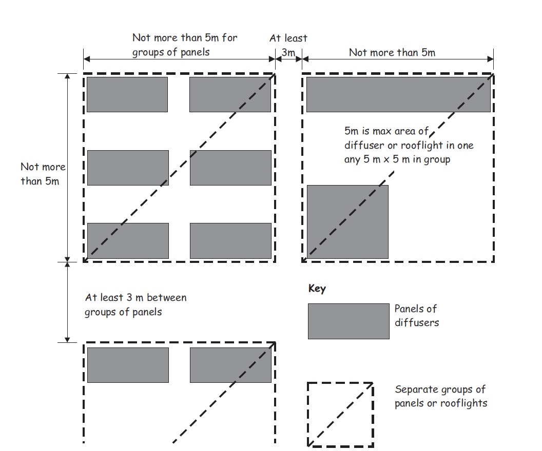
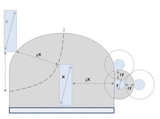
Additional information
1.X = Maximum dimension of the largest diffuser or rooflight above.
2.Y = Maximum dimension of the smallest diffuser or rooflight above.
2.5.8 Sandwich panels
A sandwich panel is a factory-made, non load-bearing component of a wall, ceiling or roof consisting of a panel having an insulated core filling the entire area between sheet metal outer facings, which may or may not have decorative and/or weatherproof coatings.
A sandwich panel used for internal walls or linings in a residential building should have a non-combustible classification.
A sandwich panel used for internal walls or linings in a non-residential building should be designed and installed in accordance with the ‘Design, Construction, Specification and Fire Management of Insulated Envelopes for Temperature Controlled Environments’, International Association of Cold Storage Contractors (European Division), 2008.
2.6 Spread to neighbouring buildings
#Source page 28
Mandatory Standard
| Standard 2.6 Every building must be designed and constructed in such a way that in the event of an outbreak of fire within the building, the spread of fire to neighbouring buildings is inhibited. |
2.6.0 Introduction
In order to reduce the danger to the occupants of other buildings, one building should be isolated from another by either construction or distance. The distance between a building and its relevant boundary is dictated by the amount of heat that is likely to be generated in the event of fire. Generally, this will be influenced by how the building is used, compartmented (see guidance to Standard 2.1), separated (see guidance to Standard 2.2) and the extent of any openings or other unprotected areas in the external wall of the building.
The guidance for fire spread to neighbouring buildings should not be assessed in isolation and reference should be made to the guidance to Standard 2.4 for fire spread in cavities and the guidance to Standard 2.7 for fire spread on external walls.
Conversions - in the case of conversions, as specified in regulation 4, the building as converted shall meet the requirements of this standard in so far as is reasonably practicable, and in no case be worse than before the conversion (regulation 12, schedule 6).
2.6.1 Fire resistance of external walls
External walls should have at least the fire resistance duration as shown in the table below, apart from the amount of unprotected area set out in clause 2.6.2. For guidance on automatic fire suppression systems, see clause 2.1.2.
The installation of an automatic fire suppression system greatly reduces the amount of radiant heat flux from a fire through an unprotected opening and this is recognised in the table to clause 2.6.1 and in the guidance to clause 2.6.2.
Table 2.6. Recommended fire resistance duration of external walls (see annex 2.D)
| Use of building | Not more than 1m from the boundary | More than 1m from the boundary | ||
|---|---|---|---|---|
| No fire suppression system | Fire suppression system | No fire suppression system | Fire suppression system | |
| Assembly building | Medium | Medium [2c] | Medium [1, 2c] | None |
| Entertainment building | Medium | Medium [2b] | Medium [2b] | Medium [1] |
| Factory and Storage building | Medium | Medium | Medium [3] | Medium [1, 4] |
| Residential building (other than a residential care building or hospital) | Medium | Medium [2b] | Medium [1, 2b] | None |
| Residential care building and hospital | Medium | Medium | Medium | None |
| Shop | Medium | Medium [2a] | Medium [2a] | Medium [1] |
| Office | Medium | Medium [2d] | Medium [1, 2d] | None |
| Open sided car park | Short | Short | None | None |
Additional information:
1.Short fire resistance duration is sufficient where the building is single-storey.
2.Short fire resistance duration is sufficient where the building is a multi-storey building and the area of any compartment does not exceed: (a) 500m2 (b) 1000m2 (c) 1500m2 (d) 2000m2 (e) 3000m2 and (f) 4000m2.
3.Short fire resistance duration is sufficient where the building is a factory (Class 2), and is single-storey.
4.No fire resistance duration is necessary where the building is a factory (Class 2).
2.6.2 Unprotected area
An unprotected area means any part of an external wall (including a door or window opening) which does not attain the appropriate fire resistance duration recommended in the table to clause 2.6.1.
An unprotected area does not include a fixed unopenable window where the frame and glazing has the appropriate fire resistance duration. Any wallhead fascia, soffit or barge board, or any cavity vents or solum vents may also be excluded from the unprotected area calculation.
Up to 500mm from boundary - where the external wall of a building is not more than 500mm from the boundary there should be no unprotected area, other than any wallhead fascia, soffit or barge board, or any cavity vents or solum vents.
500m to 1m from boundary - where the external wall of a building is more than 500mm but not more than 1m from the boundary, the level of unprotected area is limited to:
a.the external wall of a protected zone
b.an area of not more than 0.1m2, which is at least 1.5m from any other unprotected area in the same wall
c.an area of not more than 1m2, which is at least 4m from any other unprotected area in the same wall (the 1m2 unprotected area may consist of two or more smaller areas which when combined do not exceed an aggregate area of 1m2).
More than 1m from boundary - where the external wall of a building is more than 1m from the boundary, the minimum distance to the boundary may vary with the amount of unprotected area. This is derived from the use of the building and can be calculated by:
•the Enclosing Rectangle (Geometric) Method as set out in clause 2.6.3, or
•the Building Research Establishment Report ‘External fire spread: building separation and boundary distances’ (1991, BR 187), or
•The simple Geometry method - if the building is a factory (Class 2), a residential building, an assembly building or an office and is not more than 9m in height and the length of any side facing the boundary is not more than 24m, the unprotected area (in square metres) is six times the distance (in m) to the boundary. For example, if the unprotected area is 6m2, the distance to the boundary should be at least 1m and if the unprotected area is 12m2, the distance should be at least 2m and so on. If the distance to the boundary is 6m or more, the amount of unprotected area is unlimited.
2.6.3 The Enclosing Rectangle Method
The Enclosing Rectangle Method can be applied to a building or compartment more than 1m from the boundary using the Step by Step Guide below. The minimum distance from the boundary may be arrived at by interpolation between the percentages shown in the tables.
Table A should be used for storage buildings, factories (Class 1), shops, and entertainment buildings.
Table B should be used for residential buildings, offices, assembly buildings, and factories (Class 2). Table B should also be used for domestic buildings which exceed the limitations described in clause 2.6.3 of the Technical Handbook for domestic buildings.
Automatic Fire Suppression system - where the building or compartment is a shop, entertainment building, factory (Class 1) or a storage building, Table B may be used instead of Table A provided the building:
•is located more than 1m from the relevant boundary, and
•an automatic fire suppression system is installed (see clause 2.1.2) within the building.
Open sided car parks - there is no limitation on the amount of unprotected area for an open sided car park provided the external wall is more than 1m from the boundary.
Step by step guide to Enclosing Rectangle Method
Step 1 - establish a plane of reference which is the most favourable for the side of the building under consideration and which:
a.touches all or part of the side
b.however far extended, does not pass within the building, but may pass through projections such as a balcony or coping, and
c.does not cross the relevant boundary.
Normally it will be best for the plane of reference to be roughly parallel to the relevant boundary. Where the boundary distance has not been set, an assumed relationship with the relevant boundary should be made.
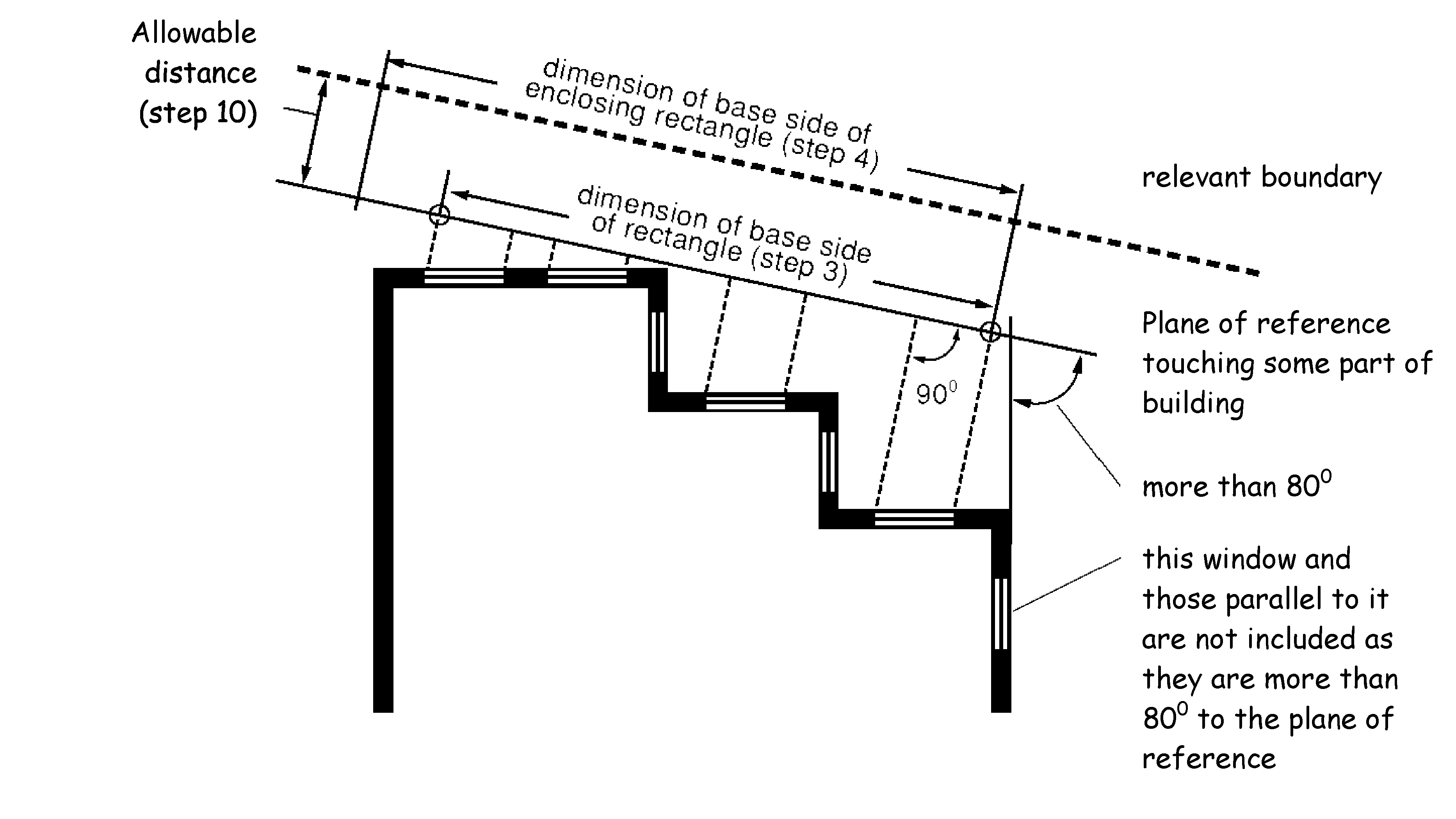
Step 2 - on the plane of reference, and at right angles to it, project lines marking those proposed unprotected areas which are 80o or less to the plane of reference. Any external side of a building which makes an angle of more than 80° with the plane of reference can be ignored in the calculation of unprotected area.
Step 3 - construct a rectangle which encloses all the unprotected areas projected onto the plane of reference following the diagrams below. See also clause 2.6.3 for combustible cladding.
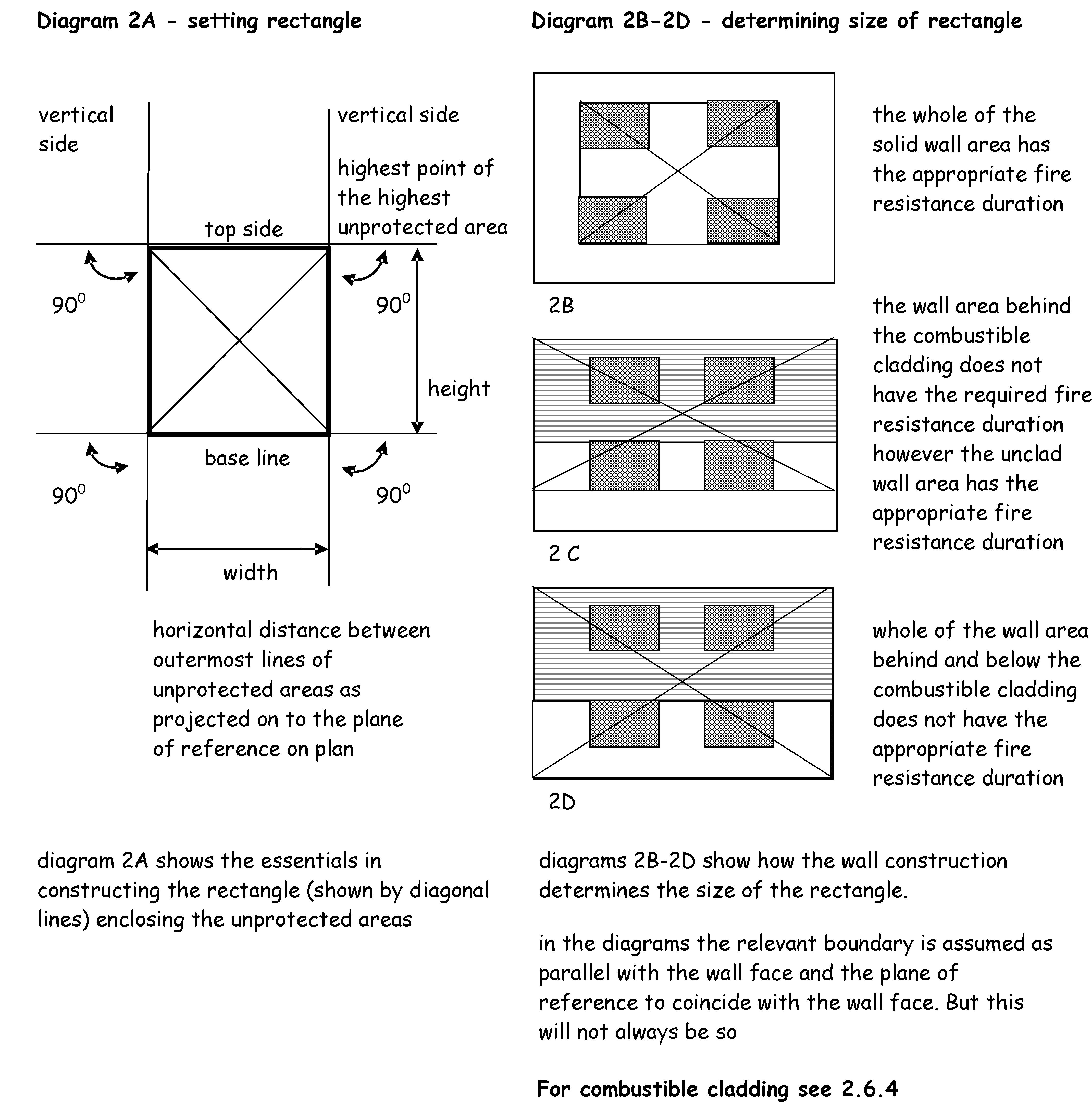
Step 4 - from the relevant table according to the use of the building or compartment, select an enclosing rectangle which is equal to, or next greater in both height and width to, the rectangle constructed under step 3. Compartmentation of the building can reduce the size of the enclosing rectangle in accordance with the diagrams below. The tables provide for enclosing rectangles of 3, 6, 9, 12, or 15m high, with widths in steps from 3m to no limit.
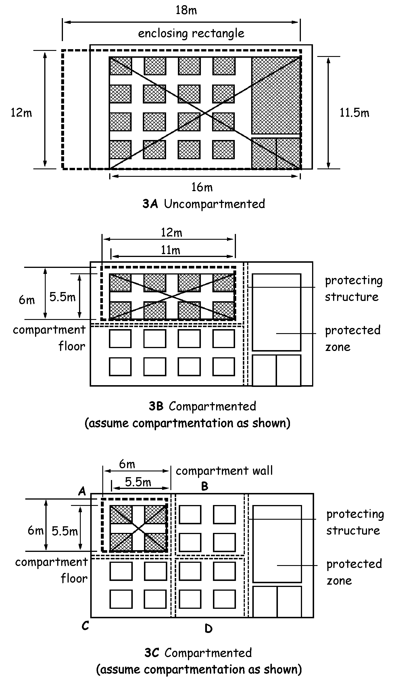
Step 5 - from the unprotected areas projected under step 2:
a.calculate their total area, and
b.express this total area as a percentage of the enclosing rectangle. This gives the unprotected percentage.
Step 6 - proceed to steps 7 to 9 where the boundary distance has been set, or steps 10 to 12 where it has not.
To find the maximum unprotected area for a given boundary position.
Step 7 - from the tables below find the unprotected percentage allowed for the distance from the relevant boundary. This distance relates to the plane of reference and not the side of the building, unless they coincide.
Step 8 - where the proposed total unprotected area relative to the size of the enclosing rectangle exceeds the allowable unprotected percentage for that distance, the design should be modified until an allowable unprotected percentage is established, and
Step 9 - repeat the process for all sides of the building situated more than 1m from any point on the relevant boundary.
To find the nearest position of the boundary for a given building:
Step 10 - from the tables below, find the minimum allowable distance for the unprotected percentage. This distance relates to the plane of reference and not the side of the building, unless they coincide.
Step 11 - repeat the process for all sides of the building, and
Step 12 - where these minimum distances are superimposed upon a plan of the building, a zone around the building is established upon which a boundary should not encroach.
Table 2.7. Table A: Storage buildings, factories (Class 1), shops and entertainment buildings
| Height of enclosing rectangle (m) | Width of enclosing rectangle (m) | Minimum distance from relevant boundary (m) for unprotected percentage not more than: | ||||||||
|---|---|---|---|---|---|---|---|---|---|---|
| 20% | 30% | 40% | 50% | 60% | 70% | 80% | 90% | 100% | ||
| 3 | 3 | 1.0 | 1.5 | 2.0 | 2.0 | 2.5 | 2.5 | 2.5 | 3.0 | 3.0 |
| 3 | 6 | 1.5 | 2.0 | 2.5 | 3.0 | 3.0 | 3.5 | 3.5 | 4.0 | 4.0 |
| 3 | 9 | 1.5 | 2.5 | 3.0 | 3.5 | 4.0 | 4.0 | 4.5 | 5.0 | 5.0 |
| 3 | 12 | 2.0 | 2.5 | 3.0 | 3.5 | 4.0 | 4.5 | 5.0 | 5.5 | 5.5 |
| 3 | 15 | 2.0 | 2.5 | 3.5 | 4.0 | 4.5 | 5.0 | 5.5 | 6.0 | 6.0 |
| 3 | 18 | 2.0 | 2.5 | 3.5 | 4.0 | 5.0 | 5.0 | 6.0 | 6.5 | 6.5 |
| 3 | 21 | 2.0 | 3.0 | 3.5 | 4.5 | 5.0 | 5.5 | 6.0 | 6.5 | 7.0 |
| 3 | 24 | 2.0 | 3.0 | 3.5 | 4.5 | 5.0 | 5.5 | 6.0 | 7.0 | 7.5 |
| 3 | 27 | 2.0 | 3.0 | 4.0 | 4.5 | 5.5 | 6.0 | 6.5 | 7.0 | 7.5 |
| 3 | 30 | 2.0 | 3.0 | 4.0 | 4.5 | 5.5 | 6.0 | 6.5 | 7.5 | 8.0 |
| 3 | 40 | 2.0 | 3.0 | 4.0 | 5.0 | 5.5 | 6.5 | 7.0 | 8.0 | 8.5 |
| 3 | 50 | 2.0 | 3.0 | 4.0 | 5.0 | 6.0 | 6.5 | 7.5 | 8.0 | 9.0 |
| 3 | 60 | 2.0 | 3.0 | 4.0 | 5.0 | 6.0 | 7.0 | 7.5 | 8.5 | 9.5 |
| 3 | 80 | 2.0 | 3.0 | 4.0 | 5.0 | 6.0 | 7.0 | 8.0 | 9.0 | 9.5 |
| 3 | no limit | 2.0 | 3.0 | 4.0 | 5.0 | 6.0 | 7.0 | 8.0 | 9.0 | 10.0 |
| 6 | 3 | 1.5 | 2.0 | 2.5 | 3.0 | 3.0 | 3.5 | 3.5 | 4.0 | 4.0 |
| 6 | 6 | 2.0 | 3.0 | 3.5 | 4.0 | 4.5 | 5.0 | 5.5 | 5.5 | 6.0 |
| 6 | 9 | 2.5 | 3.5 | 4.5 | 5.0 | 5.5 | 6.0 | 6.0 | 7.0 | 7.0 |
| 6 | 12 | 3.0 | 4.0 | 5.0 | 5.5 | 6.5 | 7.0 | 7.5 | 8.0 | 8.5 |
| 6 | 15 | 3.0 | 4.5 | 5.5 | 6.0 | 7.0 | 7.5 | 8.0 | 9.0 | 9.0 |
| 6 | 18 | 3.5 | 4.5 | 5.5 | 6.5 | 7.5 | 8.0 | 9.0 | 9.5 | 10.0 |
| 6 | 21 | 3.5 | 5.0 | 6.0 | 7.0 | 8.0 | 9.0 | 9.5 | 10.0 | 10.5 |
| 6 | 24 | 3.5 | 5.0 | 6.0 | 7.0 | 8.5 | 9.5 | 10.0 | 10.5 | 11.0 |
| 6 | 27 | 3.5 | 5.0 | 6.5 | 7.5 | 8.5 | 9.5 | 10.5 | 11.0 | 12.0 |
| 6 | 30 | 3.5 | 5.0 | 6.5 | 8.0 | 9.0 | 10.0 | 11.0 | 12.0 | 12.5 |
| 6 | 40 | 3.5 | 5.5 | 7.0 | 8.5 | 10.0 | 11.0 | 12.0 | 13.0 | 14.0 |
| 6 | 50 | 3.5 | 5.5 | 7.5 | 9.0 | 10.5 | 11.5 | 13.0 | 14.0 | 15.0 |
| 6 | 60 | 3.5 | 5.5 | 7.5 | 9.5 | 11.0 | 12.0 | 13.5 | 15.0 | 16.0 |
| 6 | 80 | 3.5 | 6.0 | 7.5 | 9.5 | 11.5 | 13.0 | 14.5 | 16.0 | 17.5 |
| 6 | 100 | 3.5 | 6.0 | 8.0 | 10.0 | 12.0 | 13.5 | 15.0 | 16.5 | 18.0 |
| 6 | 120 | 3.5 | 6.0 | 8.0 | 10.0 | 12.0 | 14.0 | 15.5 | 17.0 | 19.0 |
| 6 | no limit | 3.5 | 6.0 | 8.0 | 10.0 | 12.0 | 14.0 | 16.0 | 18.0 | 19.0 |
| 9 | 3 | 1.5 | 2.5 | 3.0 | 3.5 | 4.0 | 4.0 | 4.5 | 5.0 | 5.0 |
| 9 | 6 | 2.5 | 3.5 | 4.5 | 5.0 | 5.5 | 6.0 | 6.5 | 7.0 | 7.0 |
| 9 | 9 | 3.5 | 4.5 | 5.5 | 6.0 | 6.5 | 7.5 | 8.0 | 8.5 | 9.0 |
| 9 | 12 | 3.5 | 5.0 | 6.0 | 7.0 | 7.5 | 8.5 | 9.0 | 9.5 | 10.5 |
| 9 | 15 | 4.0 | 5.5 | 6.5 | 7.5 | 8.5 | 9.5 | 10.0 | 11.0 | 11.5 |
| 9 | 18 | 4.5 | 6.0 | 7.0 | 8.5 | 9.5 | 10.0 | 11.0 | 12.0 | 12.5 |
| 9 | 21 | 4.5 | 6.5 | 7.5 | 9.0 | 10.0 | 11.0 | 12.0 | 13.0 | 13.5 |
| 9 | 24 | 5.0 | 6.5 | 8.0 | 9.5 | 11.0 | 12.0 | 13.0 | 13.5 | 14.5 |
| 9 | 27 | 5.0 | 7.0 | 8.5 | 10.0 | 11.5 | 12.5 | 13.5 | 14.5 | 15.0 |
| 9 | 30 | 5.0 | 7.0 | 9.0 | 10.5 | 12.0 | 13.0 | 14.0 | 15.0 | 16.0 |
| 9 | 40 | 5.5 | 7.5 | 9.5 | 11.5 | 13.0 | 14.5 | 15.5 | 17.0 | 17.5 |
| 9 | 50 | 5.5 | 8.0 | 10.0 | 12.5 | 14.0 | 15.5 | 17.0 | 18.5 | 19.5 |
| 9 | 60 | 5.5 | 8.0 | 11.0 | 13.0 | 15.0 | 16.5 | 18.0 | 19.5 | 21.0 |
| 9 | 80 | 5.5 | 8.5 | 11.5 | 13.5 | 16.0 | 17.5 | 19.5 | 21.5 | 23.0 |
| 9 | 100 | 5.5 | 8.5 | 11.5 | 14.5 | 16.5 | 18.5 | 21.0 | 22.5 | 24.5 |
| 9 | 120 | 5.5 | 8.5 | 11.5 | 14.5 | 17.0 | 19.5 | 21.5 | 23.5 | 26.0 |
| 9 | no limit | 5.5 | 8.5 | 11.5 | 15.0 | 17.5 | 20.0 | 22.5 | 24.5 | 27.0 |
| 12 | 3 | 2.0 | 2.5 | 3.0 | 3.5 | 4.0 | 4.5 | 5.0 | 5.5 | 5.5 |
| 12 | 6 | 3.0 | 4.0 | 5.0 | 5.5 | 6.5 | 7.0 | 7.5 | 8.0 | 8.5 |
| 12 | 9 | 3.5 | 5.0 | 6.0 | 7.0 | 7.5 | 8.5 | 9.0 | 9.5 | 10.5 |
| 12 | 12 | 4.5 | 6.0 | 7.0 | 8.0 | 9.0 | 9.5 | 11.0 | 11.5 | 12.0 |
| 12 | 15 | 5.0 | 6.5 | 8.0 | 9.0 | 10.0 | 11.0 | 12.0 | 13.0 | 13.5 |
| 12 | 18 | 5.0 | 7.0 | 8.5 | 10.0 | 11.0 | 12.0 | 13.0 | 14.0 | 14.5 |
| 12 | 21 | 5.5 | 7.5 | 9.0 | 10.5 | 12.0 | 13.0 | 14.0 | 15.0 | 16.0 |
| 12 | 24 | 6.0 | 8.0 | 9.5 | 11.5 | 12.5 | 14.0 | 15.0 | 16.0 | 16.5 |
| 12 | 27 | 6.0 | 8.0 | 10.5 | 12.0 | 13.5 | 14.5 | 16.0 | 17.0 | 17.5 |
| 12 | 30 | 6.5 | 8.5 | 10.5 | 12.5 | 14.0 | 15.0 | 16.5 | 17.5 | 18.5 |
| 12 | 40 | 6.5 | 9.5 | 12.0 | 14.0 | 15.5 | 17.5 | 18.5 | 20.0 | 21.0 |
| 12 | 50 | 7.0 | 10.0 | 13.0 | 15.0 | 17.0 | 19.0 | 20.5 | 23.0 | 23.0 |
| 12 | 60 | 7.0 | 10.5 | 13.5 | 16.0 | 18.0 | 20.0 | 21.5 | 23.5 | 25.0 |
| 12 | 80 | 7.0 | 11.0 | 14.5 | 17.0 | 19.5 | 21.5 | 23.5 | 26.0 | 27.5 |
| 12 | 100 | 7.5 | 11.5 | 15.0 | 18.0 | 21.0 | 23.0 | 25.5 | 28.0 | 30.0 |
| 12 | 120 | 7.5 | 11.5 | 15.0 | 18.5 | 22.0 | 24.0 | 27.0 | 29.5 | 31.5 |
| 12 | no limit | 7.5 | 12.0 | 15.5 | 19.0 | 22.5 | 25.0 | 28.0 | 30.5 | 34.0 |
| 15 | 3 | 2.0 | 2.5 | 3.5 | 4.0 | 4.5 | 5.0 | 5.5 | 6.0 | 6.0 |
| 15 | 6 | 3.0 | 4.5 | 5.5 | 6.0 | 7.0 | 7.5 | 8.0 | 9.0 | 9.0 |
| 15 | 9 | 4.0 | 5.5 | 6.5 | 7.5 | 8.5 | 9.5 | 10.0 | 11.0 | 11.5 |
| 15 | 12 | 5.0 | 6.5 | 8.0 | 9.0 | 10.0 | 11.0 | 12.0 | 13.0 | 13.5 |
| 15 | 15 | 5.5 | 7.0 | 9.0 | 10.0 | 11.5 | 12.5 | 13.5 | 14.5 | 15.0 |
| 15 | 18 | 6.0 | 8.0 | 9.5 | 11.0 | 12.5 | 13.5 | 14.5 | 15.5 | 16.5 |
| 15 | 21 | 6.5 | 8.5 | 10.5 | 12.0 | 13.5 | 14.5 | 16.0 | 16.5 | 17.5 |
| 15 | 24 | 6.5 | 9.0 | 11.0 | 13.0 | 14.5 | 15.5 | 17.0 | 18.0 | 19.0 |
| 15 | 27 | 7.0 | 9.5 | 11.5 | 13.5 | 15.0 | 16.5 | 18.0 | 19.0 | 20.0 |
| 15 | 30 | 7.5 | 10.0 | 12.0 | 14.0 | 16.0 | 17.0 | 18.5 | 20.0 | 21.0 |
| 15 | 40 | 8.0 | 11.0 | 13.5 | 16.0 | 18.0 | 19.5 | 21.0 | 22.5 | 23.5 |
| 15 | 50 | 8.5 | 12.0 | 15.0 | 17.5 | 19.5 | 21.5 | 23.0 | 25.0 | 26.0 |
| 15 | 60 | 8.5 | 12.5 | 15.5 | 18.0 | 21.0 | 23.5 | 25.0 | 27.0 | 28.0 |
| 15 | 80 | 9.0 | 13.5 | 17.0 | 20.0 | 23.0 | 25.5 | 28.0 | 30.0 | 31.5 |
| 15 | 100 | 9.0 | 14.0 | 18.0 | 21.5 | 24.5 | 27.5 | 30.0 | 32.5 | 34.5 |
| 15 | 120 | 9.0 | 14.0 | 18.5 | 22.5 | 25.5 | 28.5 | 31.5 | 34.5 | 37.0 |
| 15 | no limit | 9.0 | 14.5 | 19.0 | 23.0 | 27.0 | 30.0 | 34.0 | 36.0 | 39.0 |
Additional information:
1.The minimum distance from the boundary may be arrived at by interpolation between the percentages shown.
Table 2.8. Table B: Residential buildings, offices, assembly buildings and factories (Class 2)
| Height of enclosing rectangle (m) | Width of enclosing rectangle (m) | Minimum distance from relevant boundary (m) for unprotected percentage not more than: | ||||||||
|---|---|---|---|---|---|---|---|---|---|---|
| 20% | 30% | 40% | 50% | 60% | 70% | 80% | 90% | 100% | ||
| 3 | 3 | 1.0 | 1.0 | 1.0 | 1.5 | 1.5 | 1.5 | 2.0 | 2.0 | 2.0 |
| 3 | 6 | 1.0 | 1.0 | 1.5 | 2.0 | 2.0 | 2.0 | 2.5 | 2.5 | 3.0 |
| 3 | 9 | 1.0 | 1.5 | 1.5 | 2.0 | 2.5 | 2.5 | 3.0 | 3.0 | 3.5 |
| 3 | 12 | 1.0 | 1.5 | 2.0 | 2.0 | 2.5 | 3.0 | 3.0 | 3.5 | 3.5 |
| 3 | 15 | 1.0 | 1.5 | 2.0 | 2.5 | 2.5 | 3.0 | 3.5 | 3.5 | 4.0 |
| 3 | 18 | 1.0 | 1.5 | 2.0 | 2.5 | 2.5 | 3.0 | 3.5 | 4.0 | 4.0 |
| 3 | 21 | 1.0 | 1.5 | 2.0 | 2.5 | 3.0 | 3.0 | 3.5 | 4.0 | 4.5 |
| 3 | 24 | 1.0 | 1.5 | 2.0 | 2.5 | 3.0 | 3.5 | 3.5 | 4.0 | 4.5 |
| 3 | 27 | 1.0 | 1.5 | 2.0 | 2.5 | 3.0 | 3.5 | 4.0 | 4.0 | 4.5 |
| 3 | 30 | 1.0 | 1.5 | 2.0 | 2.5 | 3.0 | 3.5 | 4.0 | 4.0 | 4.5 |
| 3 | no limit | 1.0 | 1.5 | 2.0 | 2.5 | 3.0 | 3.5 | 4.0 | 4.0 | 5.0 |
| 6 | 3 | 1.0 | 1.0 | 1.5 | 2.0 | 2.0 | 2.0 | 2.5 | 2.5 | 3.0 |
| 6 | 6 | 1.0 | 1.5 | 2.0 | 2.5 | 3.0 | 3.0 | 3.5 | 4.0 | 4.0 |
| 6 | 9 | 1.0 | 2.0 | 2.5 | 3.0 | 3.5 | 4.0 | 4.5 | 4.5 | 5.0 |
| 6 | 12 | 1.5 | 2.5 | 3.0 | 3.5 | 4.0 | 4.5 | 5.0 | 5.0 | 5.5 |
| 6 | 15 | 1.5 | 2.5 | 3.0 | 4.0 | 4.5 | 5.0 | 5.5 | 5.5 | 6.0 |
| 6 | 18 | 1.5 | 2.5 | 3.5 | 4.0 | 4.5 | 5.0 | 5.5 | 6.0 | 6.5 |
| 6 | 21 | 1.5 | 2.5 | 3.5 | 4.0 | 5.0 | 5.5 | 6.0 | 6.5 | 7.0 |
| 6 | 24 | 1.5 | 2.5 | 3.5 | 4.5 | 5.0 | 5.5 | 6.0 | 7.0 | 7.0 |
| 6 | 27 | 1.5 | 2.5 | 3.5 | 4.5 | 5.0 | 6.0 | 6.5 | 7.0 | 7.5 |
| 6 | 30 | 1.5 | 2.5 | 3.5 | 4.5 | 5.0 | 6.0 | 6.5 | 7.0 | 8.0 |
| 6 | 40 | 1.5 | 2.5 | 3.5 | 4.5 | 5.5 | 6.5 | 7.0 | 8.0 | 8.5 |
| 6 | 50 | 1.5 | 2.5 | 3.5 | 4.5 | 5.5 | 6.5 | 7.5 | 8.0 | 9.0 |
| 6 | 60 | 1.5 | 2.5 | 3.5 | 5.0 | 5.5 | 6.5 | 7.5 | 8.5 | 9.5 |
| 6 | 80 | 1.5 | 2.5 | 3.5 | 5.0 | 6.0 | 7.0 | 7.5 | 8.5 | 9.5 |
| 6 | no limit | 1.5 | 2.5 | 3.5 | 5.0 | 6.0 | 7.0 | 8.0 | 8.5 | 10.0 |
| 9 | 3 | 1.0 | 1.0 | 1.5 | 2.0 | 2.5 | 2.5 | 3.0 | 3.0 | 3.5 |
| 9 | 6 | 1.0 | 2.0 | 2.5 | 3.0 | 3.5 | 4.0 | 4.5 | 4.5 | 5.0 |
| 9 | 9 | 1.5 | 2.5 | 3.5 | 4.0 | 4.5 | 5.0 | 5.5 | 5.5 | 6.0 |
| 9 | 12 | 1.5 | 3.0 | 3.5 | 4.5 | 5.0 | 5.5 | 6.0 | 6.5 | 7.0 |
| 9 | 15 | 2.0 | 3.0 | 4.0 | 5.0 | 5.5 | 6.0 | 6.5 | 7.0 | 7.5 |
| 9 | 18 | 2.0 | 3.5 | 4.5 | 5.0 | 6.0 | 6.5 | 7.0 | 8.0 | 8.5 |
| 9 | 21 | 2.0 | 3.5 | 4.5 | 5.5 | 6.5 | 7.0 | 7.5 | 8.5 | 9.0 |
| 9 | 24 | 2.0 | 3.5 | 5.0 | 5.5 | 6.5 | 7.5 | 8.0 | 9.0 | 9.5 |
| 9 | 27 | 2.0 | 3.5 | 5.0 | 6.0 | 7.0 | 7.5 | 8.5 | 9.5 | 10.0 |
| 9 | 30 | 2.0 | 3.5 | 5.0 | 6.0 | 7.0 | 8.0 | 9.0 | 9.5 | 10.5 |
| 9 | 40 | 2.0 | 3.5 | 5.5 | 6.5 | 7.5 | 8.5 | 9.5 | 10.5 | 11.5 |
| 9 | 50 | 2.0 | 4.0 | 5.5 | 6.5 | 8.0 | 9.0 | 10.0 | 11.5 | 12.5 |
| 9 | 60 | 2.0 | 4.0 | 5.5 | 7.0 | 8.0 | 9.5 | 11.0 | 11.5 | 13.0 |
| 9 | 80 | 2.0 | 4.0 | 5.5 | 7.0 | 8.5 | 10.0 | 11.5 | 12.5 | 13.5 |
| 9 | 100 | 2.0 | 4.0 | 5.5 | 7.0 | 8.5 | 10.0 | 11.5 | 12.5 | 14.5 |
| 9 | 120 | 2.0 | 4.0 | 5.5 | 7.0 | 8.5 | 10.0 | 11.5 | 12.5 | 14.5 |
| 9 | no limit | 2.0 | 4.0 | 5.5 | 7.0 | 8.5 | 10.5 | 12.0 | 12.5 | 15.0 |
| 12 | 3 | 1.0 | 1.5 | 2.0 | 2.0 | 2.5 | 3.0 | 3.0 | 3.5 | 3.5 |
| 12 | 6 | 1.5 | 2.5 | 3.0 | 3.5 | 4.0 | 4.5 | 5.0 | 5.0 | 5.5 |
| 12 | 9 | 1.5 | 3.0 | 3.5 | 4.5 | 5.0 | 5.5 | 6.0 | 6.5 | 7.0 |
| 12 | 12 | 1.5 | 3.5 | 4.5 | 5.0 | 6.0 | 6.5 | 7.0 | 7.5 | 8.0 |
| 12 | 15 | 2.0 | 3.5 | 5.0 | 5.5 | 6.5 | 7.0 | 8.0 | 8.5 | 9.0 |
| 12 | 18 | 2.5 | 4.0 | 5.0 | 6.0 | 7.0 | 7.5 | 8.5 | 9.0 | 10.0 |
| 12 | 21 | 2.5 | 4.0 | 5.5 | 6.5 | 7.5 | 8.5 | 9.0 | 10.0 | 10.5 |
| 12 | 24 | 2.5 | 4.5 | 6.0 | 7.0 | 8.0 | 8.5 | 9.5 | 10.5 | 11.5 |
| 12 | 27 | 2.5 | 4.5 | 6.0 | 7.0 | 8.0 | 9.0 | 10.5 | 11.0 | 12.0 |
| 12 | 30 | 2.5 | 4.5 | 6.5 | 7.5 | 8.5 | 9.5 | 10.5 | 11.5 | 12.5 |
| 12 | 40 | 2.5 | 5.0 | 6.5 | 8.0 | 9.5 | 10.5 | 12.0 | 13.0 | 14.0 |
| 12 | 50 | 2.5 | 5.0 | 7.0 | 8.5 | 10.0 | 11.0 | 13.0 | 14.0 | 15.0 |
| 12 | 60 | 2.5 | 5.0 | 7.0 | 9.0 | 10.5 | 12.0 | 13.5 | 14.5 | 16.0 |
| 12 | 80 | 2.5 | 5.0 | 7.0 | 9.0 | 11.0 | 13.0 | 14.5 | 16.0 | 17.0 |
| 12 | 100 | 2.5 | 5.0 | 7.5 | 9.5 | 11.5 | 13.5 | 15.0 | 16.5 | 18.0 |
| 12 | 120 | 2.5 | 5.0 | 7.5 | 9.5 | 11.5 | 13.5 | 15.0 | 17.0 | 18.5 |
| 12 | no limit | 2.5 | 5.0 | 7.5 | 9.5 | 12.0 | 14.0 | 15.5 | 17.0 | 19.0 |
| 15 | 3 | 1.0 | 1.5 | 2.0 | 2.5 | 2.5 | 3.0 | 3.5 | 3.5 | 4.0 |
| 15 | 6 | 1.5 | 2.5 | 3.0 | 4.0 | 4.5 | 5.0 | 5.5 | 5.5 | 6.0 |
| 15 | 9 | 2.0 | 3.0 | 4.0 | 5.0 | 5.5 | 6.0 | 6.5 | 7.0 | 7.5 |
| 15 | 12 | 2.0 | 3.5 | 5.0 | 5.5 | 6.5 | 7.0 | 8.0 | 8.5 | 9.0 |
| 15 | 15 | 2.0 | 4.0 | 5.5 | 6.5 | 7.0 | 8.0 | 9.0 | 9.5 | 10.0 |
| 15 | 18 | 2.5 | 4.5 | 6.0 | 7.0 | 8.0 | 8.5 | 9.5 | 10.5 | 11.0 |
| 15 | 21 | 2.5 | 5.0 | 6.5 | 7.5 | 8.5 | 9.5 | 10.5 | 11.0 | 12.0 |
| 15 | 24 | 3.0 | 5.0 | 6.5 | 8.0 | 9.0 | 10.0 | 11.0 | 12.0 | 13.0 |
| 15 | 27 | 3.0 | 5.5 | 7.0 | 8.5 | 9.5 | 10.5 | 11.5 | 12.5 | 13.5 |
| 15 | 30 | 3.0 | 5.5 | 7.5 | 8.5 | 10.0 | 11.0 | 12.0 | 13.5 | 14.0 |
| 15 | 40 | 3.0 | 6.0 | 8.0 | 9.5 | 11.0 | 12.5 | 13.5 | 15.0 | 16.0 |
| 15 | 50 | 3.5 | 6.0 | 8.5 | 10.0 | 12.0 | 13.5 | 15.0 | 16.5 | 17.5 |
| 15 | 60 | 3.5 | 6.5 | 8.5 | 10.5 | 12.5 | 14.0 | 15.5 | 17.0 | 18.0 |
| 15 | 80 | 3.5 | 6.5 | 9.0 | 11.0 | 13.5 | 15.0 | 17.0 | 18.5 | 20.0 |
| 15 | 100 | 3.5 | 6.5 | 9.0 | 11.5 | 14.0 | 16.0 | 18.0 | 19.5 | 21.5 |
| 15 | 120 | 3.5 | 6.5 | 9.0 | 11.5 | 14.0 | 16.5 | 18.5 | 20.5 | 22.5 |
| 15 | no limit | 3.5 | 6.5 | 9.0 | 12.0 | 14.5 | 17.0 | 19.0 | 21.0 | 23.0 |
Additional information:
1.The minimum distance from the boundary may be arrived at by interpolation between the percentages shown.
2.6.4 External wall cladding
External wall cladding includes all non load-bearing external wall cladding systems attached to the structure, for example, clay or concrete tiles, slates, pre-cast concrete panels, stone panels, masonry, profiled metal sheeting including sandwich panels, weather boarding, thermally insulated external wall rendered systems, glazing systems and other ventilated cladding systems.
External wall cladding not more than 1m from a boundary should have a non-combustible classification.
A fire within the building may break-out through a window or door opening and as a consequence, the cladding, once ignited, would contribute to the heat generated from the fire. Therefore where the cladding is more than 1m from a boundary and is constructed from combustible material more than 1mm thick that has a low, medium, high or very high risk (as described in annex 2.E), the cladding should be included in the calculation of unprotected area.
However combustible cladding need not be included in the calculation of unprotected area where:
•the combustible cladding is attached to the structure of the building and the external wall contains no openings other than the small openings described in clause 2.6.2b, and
•the wall behind the cladding (or the cladding itself) has the appropriate fire resistance duration from the inside.
In addition, a cavity formed by external wall cladding should be protected in accordance with the guidance to Standard 2.4 and fire spread on external walls in accordance with the guidance to Standard 2.7.
2.6.5 Detached buildings in the same occupation
Notional Boundary - there may be a risk of fire spread between buildings even when on land in the same occupation. A notional boundary therefore is used to determine the safe distance between buildings or compartments in this situation. In order to establish whether a notional boundary calculation is necessary, the size of the opposing buildings or compartments should be established first (see diagram below).
For example, in the diagram, where the combined area of building A plus building B exceeds the maximum allowable area of any compartment as set in the tables to clause 2.1.1, then a notional boundary calculation is necessary. The designer is free to set this notional boundary at any point between the 2 buildings under consideration and this distance will determine the amount of unprotected area. The buildings should be separated by a distance not less than the sum of the distances calculated in respect of each building relative to a notional boundary in accordance with clauses 2.6.1 and 2.6.2, as if the notional boundary were a boundary (see diagram below).
Opposing compartments - a notional boundary is also necessary in the case of a single building having opposing compartments externally.
The roofs of the buildings should be separated by a distance not less than the sum of the distances provided in relation to the notional boundary in accordance with the guidance to Standard 2.8 in respect of each roof.
New and existing buildings - where a notional boundary, described above, is to be established between 2 buildings, one of which is an existing building, for the purposes of this guidance, the existing building should be regarded as if it were a new building.
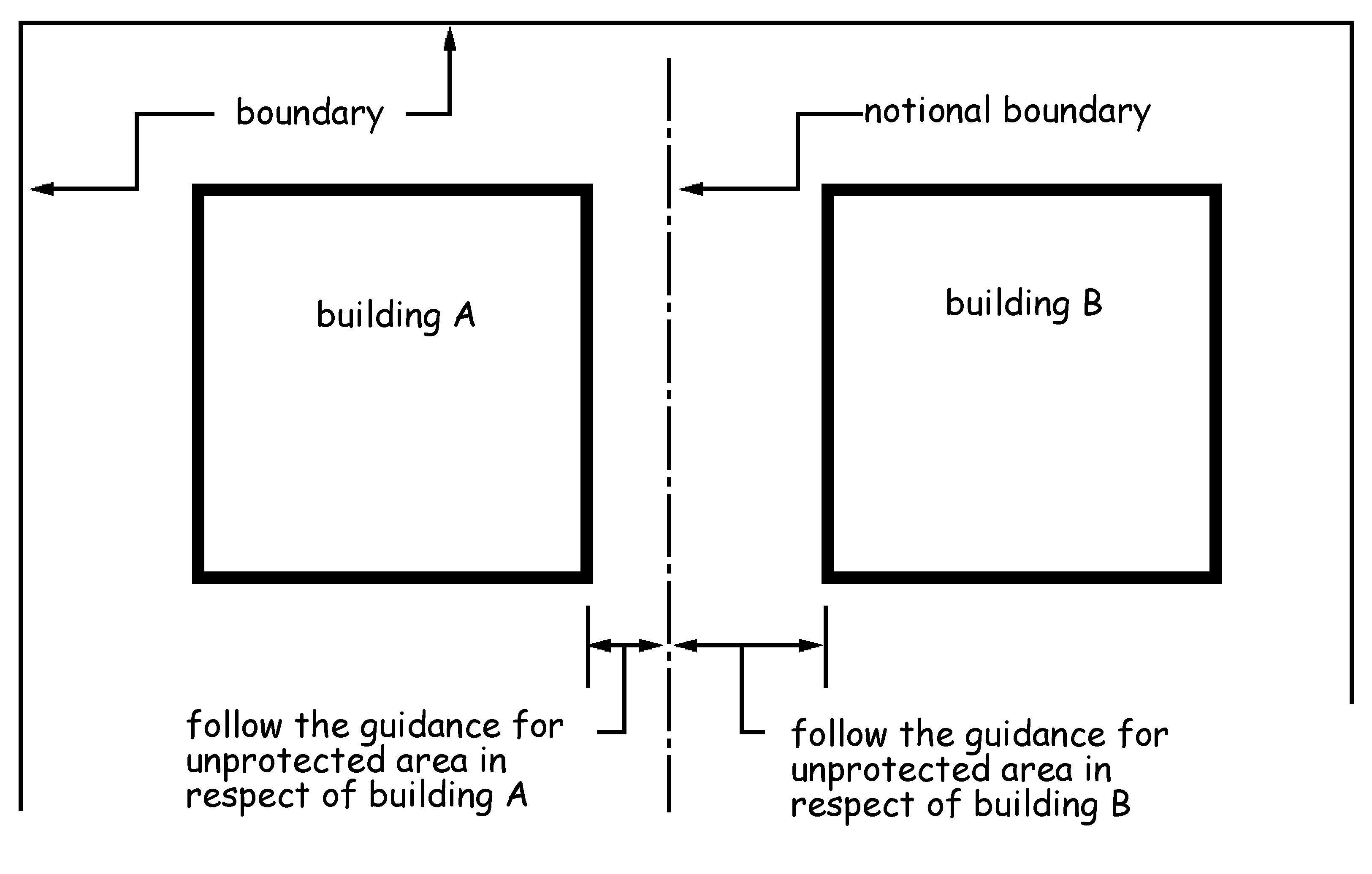
2.6.6 Combustibility
Every part of an external wall (including external wall cladding, see clause 2.6.4) not more than 1m from a boundary should be constructed of non-combustible products. This does not apply to insulation exposed in a cavity that is between 2 leaves of masonry or concrete at least 75mm thick, and which has a cavity barrier around all openings in the wall and at the top of the wall-head.
Also, in shared residential accommodation, a structural frame of combustible material which is low, medium, high or very high risk may be used not more than 1m from a boundary provided:
•no storey height is more than 18m, and
•the recommendations in clauses 2.6.1 to 2.6.3 have been followed, and
•any external wall cladding (see clause 2.6.4) is constructed from non-combustible products.
See the guidance to Standard 2.7 for additional recommendations on external wall cladding and the alternative to the need for non-combustiblity mentioned above.
2.6.7 Supporting structure
Where an element of structure provides support to an external wall (including external wall cladding) which has a fire resistance duration (as recommended in the guidance to clauses 2.6.1 and 2.6.2) the supporting element of structure should also have at least the same fire resistance duration.
2.7 Spread on external walls
#Source page 29
Mandatory Standard
| Standard 2.7 Every building must be designed and constructed in such a way that in the event of an outbreak of fire within the building, or from an external source, the spread of fire on the external walls of the building is inhibited. |
2.7.0 Introduction
There is a risk of fire spread on the external walls of a building. Fire could break-out through a window or door opening and spread onto the external walls. External walls close to the boundary are also at risk as they may be exposed to radiant heat flux from a fire in an adjoining building.
Entertainment and assembly buildings are given special consideration because of the higher risk of wilful fire-raising against the external walls (as in the Summerland fire, 1973).
Residential care buildings and hospitals also present a greater risk because the mobility, awareness and understanding of the occupants could be impaired and as a consequence, full evacuation immediately a fire is discovered may not be the most appropriate course of action.
In high rise buildings, there is a need to take further precautions as external fire spread could involve a large number of floors thus presenting greater risk both to the occupants of the building and to fire fighters. The reaction to fire characteristics of cladding materials are therefore more demanding the higher the building.
The guidance for fire spread on external walls of buildings should not be assessed in isolation and reference should be made to the guidance to Standard 2.4 for fire spread in cavities and the guidance to Standard 2.6 for fire spread to neighbouring buildings.
Conversions - in the case of conversions, as specified in regulation 4, the building as converted shall meet the requirements of this standard in so far as is reasonably practicable, and in no case be worse than before the conversion (regulation 12, schedule 6).
2.7.1 External wall cladding
External wall cladding includes non load-bearing external wall cladding systems attached to the structure, for example, clay or concrete tiles, slates, pre-cast concrete panels, stone panels, masonry, profiled metal sheeting including sandwich panels, weather boarding, thermally insulated external wall rendered systems, glazing systems and other ventilated cladding systems.
External wall cladding not more than 1m from a boundary should have a non-combustible classification.
Where the cladding is more than 1m from the boundary and is constructed from combustible products more than 1mm thick, that has a low, medium, high or very high risk (as described in annex 2.E), the cladding should be constructed from materials with a reaction to fire in accordance with the following table:
Table 2.9. Reaction to fire of external wall cladding more than 1m from boundary
| Building height | Building type | Location | Maximum level of risk |
|---|---|---|---|
| Not more than 18m above the ground | Entertainment and assembly buildings | Not more than 10m above the ground (or above a roof or any part of the building to which the general public have access) | Low risk |
| 10 – 18m above the ground | Very high risk | ||
| Residential care buildings and hospitals | Any | Low risk | |
| All other buildings | Any | Very high risk | |
| more than 18m above the ground | Any | Any | Low risk |
A cavity formed by external wall cladding should be protected in accordance with the guidance to Standard 2.4 and fire spread to neighbouring buildings in accordance with the guidance to Standard 2.6.
Alternative guidance - BR 135, ‘Fire Performance of external thermal insulation for walls of multi-storey buildings’ and BS 8414: Part 1: 2002 or BS 8414: Part 2: 2005 have been updated to include the most up-to-date research into fire spread on external wall cladding. The guidance provided in these publications may be used as an alternative to non-combustible or low risk classifications (as described in clauses 2.7.1 and 2.7.2) and for materials exposed in a cavity, as described in clause 2.4.6.
2.7.2 Wall insulation material in high rise buildings
In a building with any storey at a height of more than 18m above the ground, any insulation material situated or exposed in a cavity formed by external wall cladding should be non-combustible.
However an insulation product need not achieve a non-combustible classification where:
•the insulation product is located between two leaves of masonry or concrete at least 75mm thick, and
•the external wall is provided with cavity barriers around all openings and at the top of the wall-head.
2.8 Spread from neighbouring buildings
#Source page 30
Mandatory Standard
| Standard 2.8 Every building must be designed and constructed in such a way that in the event of an outbreak of fire in a neighbouring building, the spread of fire to the building is inhibited. |
2.8.0 Introduction
Buildings are at risk from fires starting beyond their boundaries. The area of greatest vulnerability is the roof and there may be a risk of ignition or penetration by burning brands, flames or heat. The degree of protection for roof coverings is dependent upon the distance to the boundary.
A roof covering consists of one or more layers of material such as felt, tiles, slates, sandwich panels etc, but is not intended to include the whole of the roof structure. Solar roof panels should be regarded as forming part of the roof covering and as such should be able to resist ignition from an external source. Most solar panels are glazed and their ability to inhibit fire spread can be determined by the thickness of glazing which makes up the panel (see table to annex 2.F).
A roof covering or roof light which forms part of an internal ceiling lining should also follow the guidance to Standard 2.5 Internal linings.
Conversions - in the case of conversions, as specified in regulation 4, the building as converted shall meet the requirements of this standard in so far as is reasonably practicable, and in no case be worse than before the conversion (regulation 12, schedule 6).
2.8.1 Roof coverings
The possibility of direct flame impingement from neighbouring buildings is greater where the roof covering of the building is close to the boundary. Whilst much will depend on the fire dynamics and the velocity and direction of the wind, burning brands are also likely to be more intense. For these reasons, the vulnerability of a roof covering is determined in relation to the distance of a building to the boundary.
Not more than 6m from boundary - the roof of a building, including any rooflights, but excluding any wallhead fascia, flashing or trim, boxed gutters, soffit or barge boards, should have a low vulnerability if not more than 6m from the boundary. Common materials that normally attain the criterion include, slates, tiles, glazing, sandwich panels and certain plastic materials as described in Annex 2.F.
More than 6m but not more than 24m from boundary - the roof of a building, including any rooflights, but excluding any wallhead fascia, flashing or trim, boxed gutters, soffit or barge boards, should have a low or a medium vulnerability if more than 6m but not more than 24m from the boundary. Common materials that normally attain the criterion include felts and certain plastic materials as described in Annex 2.F.
More than 24m from boundary - where a building is more than 24m from the boundary, the roof may be of any material, including materials of high vulnerability classification.
2.9 Escape
#Source page 31
Mandatory Standard
| Standard 2.9 Every building must be designed and constructed in such a way that in the event of an outbreak of fire within the building, the occupants, once alerted to the outbreak of the fire, are provided with the opportunity to escape from the building, before being affected by fire or smoke. |
2.9.0 Introduction
While the number of deaths from fires in non-domestic buildings is less than domestic buildings the potential for significant life loss and injuries is far greater. This is due to the large occupancy capacities that may be involved and the complexity of occupant behaviour including the potential for delay in occupant evacuation following the outbreak of fire.
Occupants in buildings do not normally perceive themselves to be at risk from fire and are not fully aware of the speed that fire can spread. The risk to occupants is greater if they are asleep during the outbreak of fire as their ability to detect a fire and to escape will be greatly impaired.
Everyone within a building should be provided with at least one means of escape from fire that offers a safe passage to a place of safety outside the building. This should allow for them to escape from the building before being affected by fire or smoke. In certain circumstances, for example, where the travel distance is excessive, a second means of escape should be provided. This will allow the occupants to turn away from the fire and make their escape in the other direction. There may be up to four stages in the process of escape:
•escape from the room of fire origin or escape from the fire where only one direction is possible
•escape from the compartment of fire origin or until the safety of a fire resisting wall is reached
•escape from the floor of fire origin to protected zones and escape stairs, and
•escape from the building to a place of safety at ground level.
Due to the special fire precautions within residential care buildings, hospitals and enclosed shopping centres, additional guidance is provided in the annexes. However it is important to remember that the guidance in the annexes is in addition and supplementary to the guidance to Standard 2.1 to 2.15. For additional guidance on:
•residential care buildings, see annex 2.A
•hospitals, see annex 2.B
•enclosed shopping centres, see annex 2.C.
Conversions - in the case of conversions, as specified in regulation 4, the building as converted shall meet the requirement of this standard (regulation 12, schedule 6).
2.9.1 Escape principles
The occupants should be able to leave the building or part of the building in relative safety during the outbreak of a fire without assistance from the fire and rescue service.
Designers generally achieve this by providing independent routes of escape either directly to a place of safety, or through an adjacent compartment or protected zone.
The time available to leave a room or compartment of fire origin before being overcome by fire or smoke is dependant on a number of key factors:
•the number and mobility of occupants in the compartment or room of fire origin
•the containment measures of the room or compartment of fire origin
•the geometry of the room or compartment
•means of early warning of fire
•the fire dynamics (e.g. the fire load and the rate of fire growth)
•the distance to reach a place of safety, a protected zone or another compartment, and
•the number and width of exits.
There are many options available to designers when considering escape from buildings to a place of safety. However these options can be subdivided into 3 broad categories:
•direct escape
•internal escape
•external escape.
Direct escape means that occupants can escape from a building directly to a place of safety by way of a final exit door without using an internal or external escape route. Whilst direct escape to a place of safety is preferable, this is not always possible or convenient, for example, in hospitals or multi-storey buildings with many floors high above the ground.
Internal escape is perhaps the most common method of escape from buildings. Occupants escape from fire using enclosed corridors and stairs inside the building to reach a final exit door from the building, which leads to a place of safety.
External escape routes are wholly or partially open to the external air therefore the risk of smoke logging is reduced compared with enclosed escape routes inside the building. External escape routes include external escape stairs, access decks and flat roofs. In certain circumstances, an escape route from a building may be by way of a flat roof or an access deck.
2.9.2 Occupancy capacity
The use of a building and its occupancy capacity can vary considerably. It is necessary therefore to calculate the appropriate number of occupants in each space for normal circumstances.
The occupancy capacity can be estimated by assigning a floor area per occupant, this is called the occupancy load factor. The occupancy capacity of a room or space (without fixed seating) can then be obtained by dividing the area in square metres by the relevant occupancy load factor. While some buildings such as residential buildings are designed for a definitive number of occupants other occupancies such as in offices can vary.
The table below is based on the following characteristics of the occupancy:
•assembly and entertainment buildings, which may have high occupancy density and large undivided floor areas
•offices, where desks, cabinets and office machinery will be present
•shops, where display shelves, counters and racks will be present
•residential buildings, where the number of occupants is generally controlled by the number of beds available
•factory and storage buildings, where the occupancy capacity is normally low and goods or machinery will be present.
The values in the table can be used as a guide to assess the occupancy capacity of a room. Where the occupancy load factors listed in the table below are not used, a written statement of the occupancy capacity should be submitted to the verifier who may wish to confirm the figures (e.g. occupancy capacity may be based on the number of available seats; the figure should include the number of spaces available for wheelchair users).
Table 2.10. Occupancy capacity in rooms and spaces without fixed seating
| Description of room or space | Occupancy load factor |
|---|---|
| Standing spectators’ area | 0.3 |
| Amusement arcade, assembly hall (including a general-purpose place of assembly), bar (public area), bingo hall | 0.5 |
| Concourse, dance floor, queuing area | 0.7 |
| Committee room, common room, conference room, dining room, licensed betting office (public area), lounge (other than a lounge bar), meeting room, reading room, restaurant, staff room, waiting room | 1.0 |
| Exhibition hall | 1.5 |
| Shop sales area [2a] | 2.0 |
| Art gallery, dormitory, factory production area, museum, workshop | 5.0 |
| Office | 6.0 |
| Kitchen, library, shop sales area [2b] | 7.0 |
| Bedroom or study bedroom | 8.0 |
| Bed-sitting room, billiards room | 10.0 |
| Car park, storage and warehouse accommodation | 30.0 |
Additional information:
1.The occupancy capacity in enclosed shopping centres should be calculated in accordance with annex 2.C.
2.Shop sales area are classified as follows:
3.The descriptions; arcade, hall, gallery and room used in the table do not indicate a particular design or configuration of building.
2.9.3 Travel distance
Travel distance is the term applied to the distance that occupants have to travel to a protected door and is measured along the actual route of escape from any point within a storey, including the distance across rooms.
The further occupants need to travel within a building to reach a protected door the greater the risk from the effects of fire. The travel distance should allow for the occupants to reach a protected door before being overcome by fire or smoke. This distance will depend on the nature of the fire and the characteristics of the occupants.
Occupants should be able to reach a protected door before there is a noticeable accumulation of smoke in the route of escape.
Therefore, to provide for safe evacuation of the occupants, it is necessary to have limitations on the distance occupants should have to travel to reach a protected door.
The limitations on travel distances reflect the different levels of protection that are necessary for the building occupants, based on the fire hazard and occupancy profile. The distances and available directions of travel, given in the following table and the guidance on travel distance, reflect this philosophy.
Table 2.11. Recommended travel distance (m)
| Occupancy profile | Building use [1] [2] [3] | One direction of travel | More than one direction of travel |
|---|---|---|---|
| Very slow evacuation | Residential care buildings (e.g. nursing homes and residential schools for children etc). Buildings primarily for disabled people, or people with learning difficulties. Swimming pools in air supported structures | 9 [4] | 18 [4] |
| Slow evacuation | Residential buildings (other than residential care buildings and hospitals) (e.g. hotels, hostels etc), entertainment buildings, assembly buildings, shops, room or auditorium with provision for fixed seating, storage building (Class 1) other than a bonded warehouse containing spirituous liquor | 15 | 32 |
| Medium evacuation | Offices, storage building (Class 2), open sided car parks, bonded warehouse containing spirituous liquor and factories | 18 [5] | 45 |
| Other | From a roof top plant room in the open air | 60 | 100 |
| Other | Within plant rooms or within roof top plant rooms | 18 | 45 |
| Other | Within a place of special fire risk | 9 | 18 |
| Other | Within a protected zone to a place of safety | 100 | unlimited |
Additional information:
1.For additional guidance on residential care buildings, see annex 2.A.
2.For additional guidance on hospitals, see annex 2.B.
3.For additional guidance on enclosed shopping centres, see annex 2.C.
4.If the building also contains a room or auditorium with provision for fixed seating, the more demanding travel distances should be used.
5.In a silage or grain store on a farm where the material is handled primarily by mechanical plant, the distance is 30m.
2.9.4 Measurement of travel distance
Travel distance is the distance measured along the actual route of escape from any point within a storey to the nearest protected door giving direct access to:
•a place of safety, or
•another compartment, or
•a protected zone, or
•an external escape stair, or
•a flat roof or access deck, or
•to a door in a sub-compartment wall as described in annex 2.A and annex 2.B.
In the case of a building which has only 1 direction of travel, the travel distance should be measured to a protected door giving access to an escape stair or a place of safety. In the case of a building or part of a building where there are at least 2 available directions of travel, the travel distance may be measured to any protected door.
Obstructions - where a floor is divided by fixed seating or other fixed obstructions, the travel distance should be measured by way of the shortest route along open seatways, gangways or circulation areas.
Internal stairs - where a measurement of travel distance includes an internal unenclosed escape stair, the travel distance should be measured along the pitch line from the centre of the nosing of the topmost tread to the lower landing, including the length of any intermediate landings.
2.9.5 Head room
An escape route and circulation area should have a clear headroom of at least 2m. In a doorway it may be reduced to not less than 1.9m.
2.9.6 Horizontal evacuation
In progressive horizontal evacuation, occupants within separate compartments remote from the fire may not need to evacuate the building. They may be able to remain within the building until the fire and rescue service has dealt with the fire or, if required, commence evacuation into an adjoining compartment or escape direct to the outside. The objective is to provide a place of relative safety within an adjoining compartment, from which further evacuation can be made if necessary but under less pressure of time.
Where the travel distance is measured to a protected door in a compartment wall:
1.there should be no fire shutter in that compartment wall, and
2.if the compartment does not contain either a final exit or direct access to a protected zone, then each of the adjoining compartments, should have at least 1 other escape route, which is not through a further compartment, and
3.the area of the adjoining compartment is:
A fire in any one compartment should not prevent the occupants of any other compartment area from reaching a final exit.
See annex 2.A for additional guidance on residential care buildings and annex 2.B for hospitals.
2.9.7 Number of exits
To assess the numbers of exits required from the storey, the occupancy of the whole storey must be assessed. There is no need however to include adjoining parts of the building where the adjoining part does not communicate with the part under consideration.
The evacuation time from a room or storey is controlled by the number of exits and the time taken for occupants to pass through the exits. The fewer and narrower the exit the longer it can take for occupants to leave a room or storey, this is liable to cause irritation among those waiting, which in an emergency may lead to panic and crushing. Exits must therefore be numerous and wide enough to discharge the occupants before such conditions occur.
The number of escape routes from a room or storey exits relates to:
a.the use and occupancy profile within the building
b.the occupancy capacity
c.the height of a storey above the ground or the depth below ground, and
d.the travel distance involved.
To provide the occupants with the opportunity to move away from the effects of fire and smoke, on each storey of a building there should be sufficient exits to one or more of the following:
•an escape stair
•another compartment
•a protected zone, or
•directly to a place of safety.
In hospitals, the number of storey exits increase in proportion to the number of patient beds (see annex 2.B).
Room exits - it is important to realise that evacuating occupants from a building is dependant not only on the time it takes to reach an exit but also on the number that can be discharged through an exit in a given time. The tables below state the minimum number of exits that should be considered for a room depending on its occupancy capacity. For the purposes of this guidance, reference to a room shall include reference to a gallery, catwalk or openwork floor.
Table 2.12. Minimum number of room exits
The table below states the minimum number of exits that should be provided for a storey related to its occupancy capacity.
Table 2.13. Minimum number of storey exits
Additional information:
At least 2 storey exits should be provided from:
1.any storey at a height of more than 7.5m
2.any storey in a residential care building or hospital
3.a basement storey at a depth of more than 4.5m; or a basement storey which is intended to be used by members of the general public (other than a basement storey providing access only to sanitary accommodation).
Single escape stair - it is possible to design a building with part of the upper storey at a height of not more than 7.5m to have only one escape route where the remainder of the storey has two escape routes. In cases where escape is by way of a single escape stair, access to the escape stair should be by way of a protected lobby.
Room exits to storey exits - where a room is located on a storey, which, due to the occupancy capacity, height of the storey or travel distance, is recommended to have 2 or more storey exits, the escape routes from the room exits to the storey exits should be designed as follows:
a.where only 1 room exit is provided, the escape route from the room should lead to 2 independent storey exits. However this need not be provided to:
b.where the occupancy capacity of a room is not more than 100, the room exits may give access to the same space provided the guidance for alternative directions of escape has been followed.
c.where the occupancy capacity of a room is more than 100, the room exits may also give access to the same space provided:
2.9.8 Escape route widths
To assist in the movement of occupants and reduce anxiety during an evacuation, escape routes should be wide enough to allow occupants to escape safely. The following recommendations for the width of escape routes are based on the speed and number of occupants that can move along an escape route together.
The aggregate unobstructed width in mm of all escape routes from a room, or storey, should be at least 5.3 x the occupancy capacity of the room or storey.
When a room or storey requires 2 or more escape routes, consideration should be given to the impact of one of the exits being affected by fire. The remaining exits, should be wide enough to allow all occupants sufficient time to leave the room or storey safely. Under these circumstances, when calculating the width of exits, the largest exits should be discounted. The aggregate width of the remaining exits need to be capable of accommodating the total number of occupants of the room or storey.
The guidance on the width of exits assumes a unit width of 530mm per person and a rate of discharge of 40 persons per minute. In theory a corridor 530mm wide would be capable of discharging 100 occupants in 2.5 minutes, but such a width would not allow occupants to move around freely and without difficulty, to the best of their ability. The unobstructed width of each individual escape route should be at least 1200mm to assist occupants with sensory, cognitive and/or mobility impairments. However where only stepped access is provided to a part of the building, the escape route may be reduced as follows:
•in buildings with not more than 225 occupants the minimum width may be reduced to 1100mm
•in buildings with not more than 100 occupants the minimum width may be reduced to 1000mm.
Doorways can reduce the width of escape routes by 150mm. This nominal reduction allows for the construction of door frames, however:
•where the number of occupants using the escape route is not more than 225, the clear opening width of the doorway should be at least 850mm
•where the number of occupants using the escape route is not more than 100, the clear opening width of the doorway should be at least 800mm.
The clear opening width at doorways is measured in accordance with the diagram below:
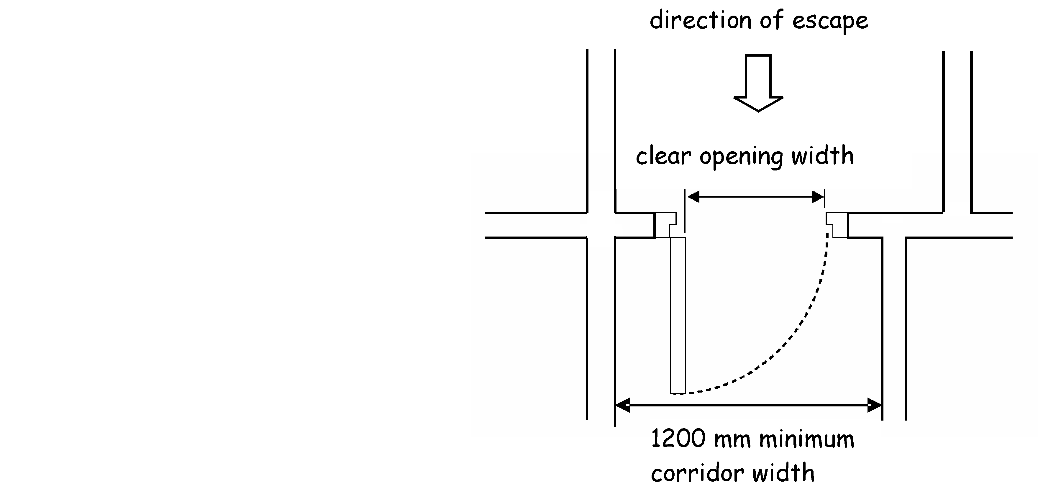
Constancy of width - an escape route should not narrow in the direction of escape. However an escape route may pass through a wider circulation area leading to a narrower circulation area provided the latter is of a width at least that recommended for the escape route. Width of escape stairs is covered in clause 2.9.31.
The strict application of the above guidance may not be appropriate in all cases as follows:
•a hospital, where staff will move bed patients into a safe area within the building, or
•enclosed shopping centres where the mall is regarded as a place of relative safety.
More detailed guidance for hospitals is provided in annex 2.B and for enclosed shopping centres in annex 2.C.
2.9.9 Direction of escape
Everyone within a room when confronted by an outbreak of fire should be provided with at least one means of escape that offers safe passage to an exit from that room.
A layout, which only follows the recommendations for travel distance and number of storey exits, may still result in an undesirable layout. For example if two exits are placed close together it may make it impossible for all occupants to reach either exit if the fire is close to the exits. It is essential therefore, that where more than one exit is provided they are located so that at least one exit is available.
In many cases, there will not be an alternative at the beginning of the route. For example, there may be only one exit from a room to a corridor, from which point escape is possible in two directions. This is acceptable provided the distance the occupants have to travel, to the point where they can diverge in two or more directions, follows the relevant guidance in clause 2.9.3 for one direction of travel, and the overall route to a protected zone or place of safety follows the recommendations for more than one direction of travel.
Where more than one room exit is provided, the directions of travel from any point within the room should:
•diverge at an angle of at least 45°, or
•be combined for a distance not more than that allowed for one direction of travel and then diverge to two exits at an angle of at least 45° plus 2½° for every metre travelled in one direction (see table to clause 2.9.3).
To reduce the risk of 2 room exits becoming impassable due to fire or smoke in the early stages of fire growth, the distance between the exits from the room should be more than twice the distance travelled in one direction.
2.9.10 Escape from inner room
Occupants within an inner room could become trapped where there is an outbreak of fire in the adjoining access room. Therefore, escape should only be by way of one other room, and the inner room should:
•not be used as sleeping accommodation
•have an escape route that does not pass through more than one access room
•the access room should be fitted with a suitable automatic fire detection and alarm system to warn the occupants of the inner room of an out break of fire
•the access room should not be a place of special fire risk.
2.9.11 Fixed obstructions/furnishings
Storage areas of buildings with fixed obstructions should provide unobstructed access to an exit. Access to an exit in such buildings may be by way of a gangway. The width of gangways between fixed obstructions (including fixed racking or shelving and high-bay storage) should be at least 530mm. Due to the low occupancy and limited occupation in a building for the bulk storage of spirituous liquor, the width may be reduced to at least 400mm.
Fixed seating or furnishings - in a building, or part of a building, with fixed seating or fixed seating and fixed tables or other floor fixtures, there should be access to an exit by way of a gangway or a seatway, or a seatway directly to an exit; or a circulation area in accordance with the table and diagram below and:
•in the case of an auditorium that has more than 1 exit, at least 1 exit should be provided at least two-thirds of the distance from any stage, screen or performing area towards the back of the room, and
•a gangway or exit door should be provided at each end of a row of more than 12 fixed seats, and
•in the case of shops where the room, or part of the room, has an occupancy capacity of more than 100, the minimum width of a circulation area should be designed as if the circulation area were an escape route, or
•in the case of buildings to which the Safety of Sports Grounds Act 1975 applies, it is appropriate to use the Guide to safety at sports grounds http://www.culture.gov.uk. Figure 2.8. Plan of room with provision for fixed seating Figure 2.9. Method of measuring seatway widths
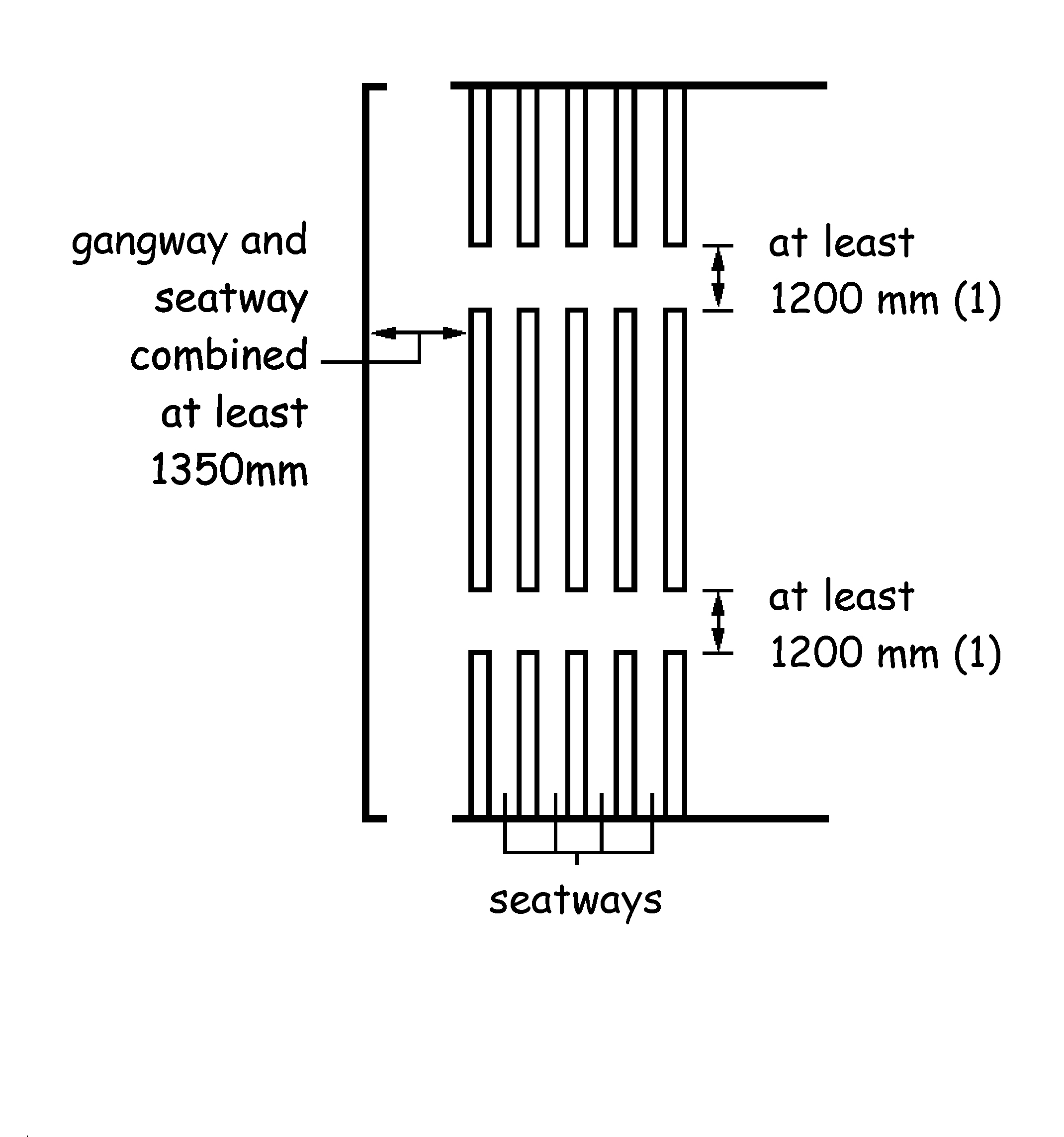
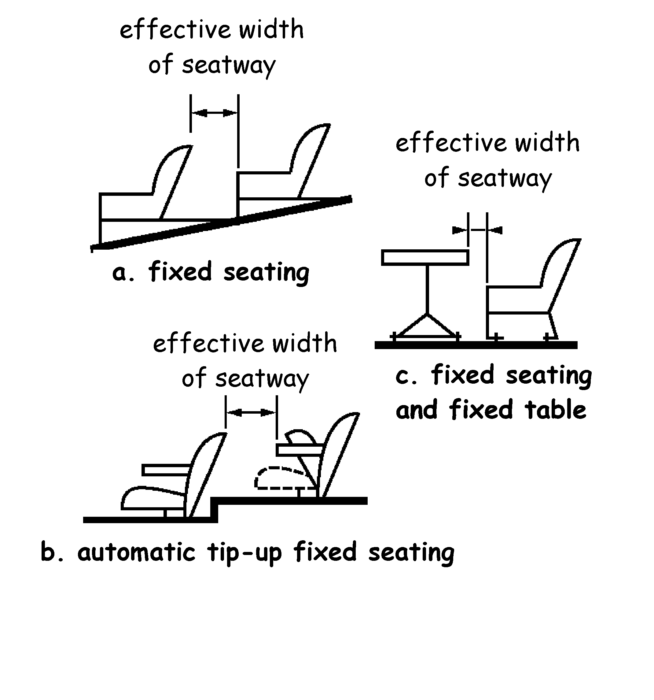
Table 2.14. Minimum width of gangways & seats in a room with fixed seating
| Situation | Number of seats in a row with Gangway one side | Number of seats in a row with Gangway on both sides | Minimum or effective width (mm) |
|---|---|---|---|
| Gangway | Not applicable | Not applicable | 1200 [1] |
| Gangway and seatway combined | Not applicable | Not applicable | 1350 |
| Seatway | 2 | 2-4 | Not applicable |
| Seatway | 3-7 | 5-14 | 300 |
| Seatway | 8 | 15, 16 | 325 |
| Seatway | 9 | 17, 18 | 350 |
| Seatway | 10 | 19, 20 | 375 |
| Seatway | 11 | 21, 22 | 400 |
| Seatway | 12 | 23, 24 | 425 |
| Seatway | - | 25, 26 | 450 |
| Seatway | - | 27, 28 | 475 |
| Seatway | - | More than 28 (limited by travel distance)[2] | 500 |
Additional information:
1.May be reduced to 900mm where the occupancy capacity of the room is not more than 60.
2.The travel distance should be measured by way of the shortest route along open seatways, gangways or circulation areas.
2.9.12 Escape routes in residential buildings
In residential buildings occupants are particularly vulnerable to fire when asleep. Occupants may also be unfamiliar with their accommodation and escape routes. Those occupants on the fire floor should be provided with the opportunity to reach a protected zone (or other escape route) in relative safety and as quickly as possible, therefore, the movement of fire and smoke to the escape route should be inhibited.
In a residential building, where any corridor escape route serves sleeping accommodation it should be constructed of walls providing a short fire resistance duration and any door in the wall should be a suitable self-closing fire door with a short fire resistance duration. However the fire door to the cleaners cupboard need not be self closing provided it is lockable.
This guidance may need to be adapted in a residential building used as a place of lawful detention due to the unique operational factors.
For additional guidance on residential care buildings and hospitals see annex 2A and 2B.
2.9.13 Fire and smoke control in corridors
The first hazard to occupants beyond the room of fire origin is likely to be from the products of combustion. Any migration of fire and smoke to an escape route may deter occupants from using it.
Every corridor, that is used as an escape route that exceeds the dimensions in the guidance below, should be:
•subdivided with a wall or screen with a short fire resistance duration, or
•protected by the installation of a smoke control system.
Where the corridor is subdivided by a wall or screen with a short fire resistance duration (insulation criteria need not be applied) any door in the wall or screen should be a self-closing fire door and:
•where the corridor is a dead end more than 4.5m long and provides access to a point from which more than 1 direction of escape is possible, it should be divided at that point or points, as shown in the diagram below and
•where the corridor provides at least 2 directions of escape and is more than 12m in length between the exits it serves, it should be divided in the middle third of the corridor. This does not mean that the corridor should be subdivided into 12m lengths.
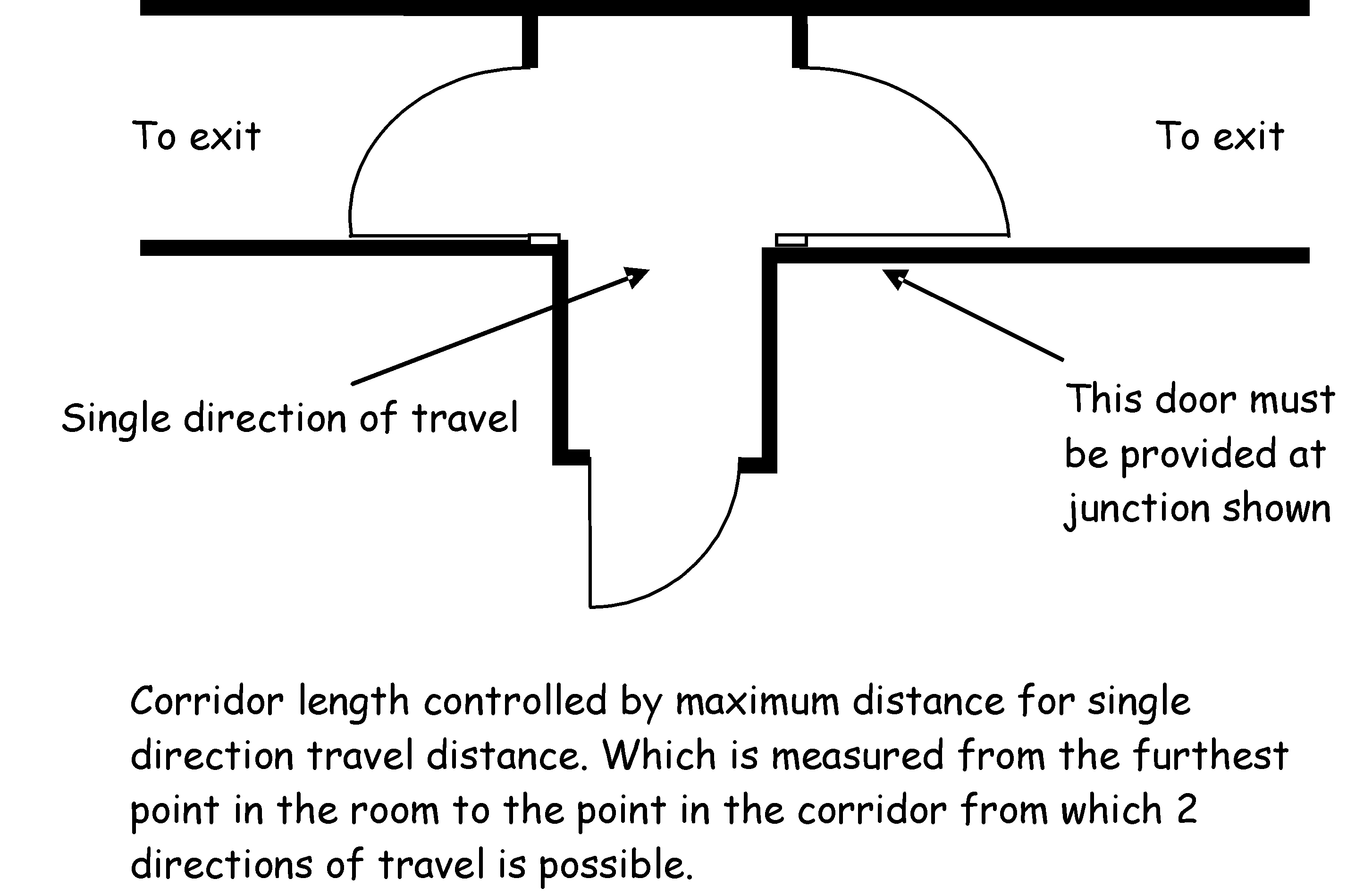
Where a cavity extends across any of the self closing fire doors identified above, or above the walls described in clause 2.9.12 a cavity barrier with at least short fire resistance duration should be fitted above the sub-dividing wall and fire door to inhibit fire and smoke spread.
Smoke control systems - when a design incorporates a smoke control system in a building, other than a residential care building or hospital, it should employ smoke differentials in accordance with BS EN 12101: Part 6: 2005, but assuming a minimum pressure difference (over the wall being assessed) of 25 Pa based on a wind speed of 22m/sec. Mechanical smoke ventilation using pressure differentials may be used to inhibit smoke spread into escape routes by means of:
•depressurisation systems, or
•pressurisation systems.
The merits and limitations of each system should be assessed before deciding which system to choose.
A depressurisation system is based on the principle of extracting smoke to the outside air. This creates a negative pressure in the space relative to the adjacent spaces. Where a smoke ventilation depressurisation system is used, replacement air should be provided for the system to operate effectively. The volume of air and smoke removed should be replaced with the equivalent volume of replacement air at a sufficient rate in order to ensure a smoke flow out of the building. Reducing the rate of replacement air can result in the smoke ventilation system becoming less efficient whereas increasing replacement air and extraction at high velocities can produce air pressure conditions which make doors difficult to open. The system should be balanced to ensure that the forces required to open doors are not greater than those specified in Section 4 Safety.
A pressurisation system is based on the principle of forcing air into the escape route which helps to keep smoke out. Forced air can be used to maintain a positive pressure in the escape route which produces an air flow through gaps around doors preventing the smoke from entering. The system design should take account of likely pressure reduction when occupants open doors to escape or when fire-fighters open doors to access the fire. The system should be balanced to ensure that the forces required to open doors are not greater than those specified in Section 4 Safety.
2.9.14 Openings in floors
In the event of a fire, there is always a risk that an opening in a floor could result in a proportion of fire or smoke and toxic fumes arising from a fire flowing up through the opening leading to a build-up of smoke on the upper storeys. This can pose a threat to life safety, particularly when the occupants are unfamiliar with the building. Smoke and flames rising through such an opening in a floor may impede evacuees from leaving the building. It is important when such a design is considered that it does not impair the ability of the occupants to escape. Occupants should be able to move directly away from the opening or continue their evacuation at a safe distance away from the edge of the opening.
Escape routes should not be compromised by openings between floors, such as at an escalator and fire safety measures are necessary to compensate for this increased level of hazard; the diagram below explains this principle.
In a building where there is an opening in any floor, not being a compartment floor or separating floor, an escape route should not be within 4.5m of the openings unless:
•the direction of travel is away from the opening, or
•there is an alternative escape route, which does not pass within 4.5m of the opening, or
•a wall or screen with a short fire resistance duration for integrity is provided between the opening and the route of escape.
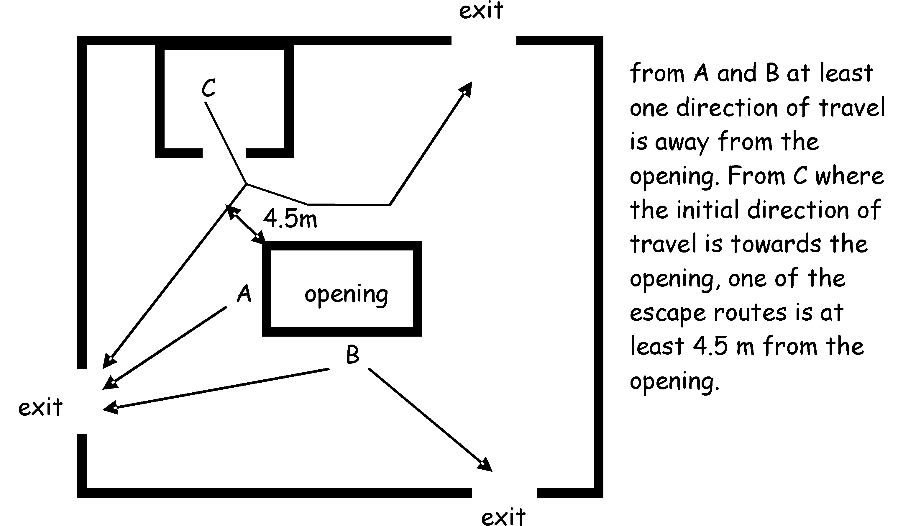
2.9.15 Obstacles
Time can be a critical factor in ensuring occupants can leave the building before being overcome by the effects of fire and smoke. It is important therefore that an escape route provides a clear unobstructed route that does not restrict the flow of occupants.
To ensure the safe and smooth movement of occupants and prevent unnecessary increase in anxiety during an evacuation the following should not be part of an escape route:
•a lift, or
•an escalator, or
•a turnstile, other than a suitably designed and installed turnstile unit with an emergency break out facility enabling the entire unit to open in the direction of escape, or
•any shutter; other than one which is installed for security purposes across a shop front and which does not close automatically in the event of fire, or
•a manual sliding door, accessible to the public.
A fixed ladder may be used to escape from a plant room (not being a place of special fire risk), which is unoccupied other than for maintenance purposes.
Revolving doors and automatic doors can obstruct the passage of persons escaping. However they may be installed in an escape route if designed and installed in accordance with BS 7036: 1996 and are either:
•arranged to fail safely to outward opening from any position of opening, or
•provided with a monitored fail-safe system for opening the door from any position in the event of mains supply failure and also in the event of failure of the opening sensing device, and
•opens automatically from any position in the event of actuation of any fire alarm in the fire alarm zone within which the door is situated.
2.9.16 Direction of door openings
Doors across an escape route can slow the flow of occupants and may lead to crowding. To ensure that doors on an escape route do not unduly delay escape they should open in the direction of escape. However doors across an escape route may open against the direction of escape where the occupancy capacity in the building, or part of the building is low as follows:
•in a factory building or storage building where the occupancy capacity is not more than 10
•in any other building where the occupancy capacity is not more than 60.
However if the door is an emergency door or a door serving a place of special fire risk, the side-hung door should open in the direction of escape regardless of occupancy levels.
2.9.17 Galleries
For the purposes of compliance with this standard a gallery is an integral part of the room into which it projects, and the occupants of a gallery would have the same awareness of an outbreak of fire in a room as the other occupants of that room. The limitations on the size of a gallery relative to the room into which it projects is to provide those occupants on the gallery with the same awareness of any outbreak of fire.
The safety of those using a gallery, relates to:
•the use and occupancy characteristics within the room, and
•the occupancy capacity, and
•the travel distance, and
•the number of escape routes.
A gallery should be open above and below to the room into which it projects and should not give access to any other room, other than a room with a means of escape independent of the gallery. The gallery may be wholly or partly enclosed below, where:
•the floor of the gallery has a short fire resistance duration, and
•at least 1 route of escape from the gallery is by way of a protected door.
2.9.18 Locks
Locks on exits doors or locks on doors across escape routes present difficulties when assessing the need for security against the need to allow safe egress from a building in the event of a fire. Security measures however should not compromise the ability of the occupants to escape from a building in an emergency.
In general, all doors on escape routes, should either not be fitted with locks, or they should only be fitted with fastenings that can be readily operated from the side approached by occupants making an escape. The operation of these locks should be readily apparent, without the use of a key or access control tokens and without having to manipulate more than one mechanism. This is not intended to prohibit the use of locks to secure a room, storey or building when unoccupied. This guidance may also need to be adapted in a building used as place of lawful detention due to the unique operational factors.
Where an exit door from a room, storey or a door across an escape route has to be secured against entry when the building or part of the building is occupied, it should only be fitted with a lock which is readily operated, without a key, from the side approached by occupants making their escape. Similarly, where a secure door is operated by a code, combination, swipe or proximity card, biometric data or similar means, it should also be capable of being overridden from the side approached by occupants making their escape (see also electrically operated locks).
Guidance on the types of hardware for timber fire and escape doors can be obtained from the Code of Practice, 'Hardware for Fire and Escape Doors' Issue 2, June 2006, published by the Door and Hardware Federation and the Guild of Architectural Ironmongers.
2.9.19 Mechanical or electro-mechanical panic exit locking devices
Different groups of users will have differing needs to enable them to escape quickly and easily from a building in the case of fire and this should be reflected in the type of lock chosen. For example, in buildings frequented by the general public it is important that the locks can be released by occupants who may be unfamiliar with the building and have received no training in the emergency procedures or the types of exit locks used in the building.
These locks are designed to operate on body pressure alone and require no knowledge of their operation to enable safe and effective evacuation of the building. In these cases, panic exit locks operated by a horizontal bar should be designed and installed in accordance with BS EN 1125: 1997.
2.9.20 Mechanical or electro-mechanical emergency exit locking devices
In buildings, or parts of buildings, that are not open to the general public, such as in offices or other working environments, the occupants should be awake and familiar with the building. When staff in such areas are trained both in the emergency procedures and in the use of the specific emergency devices fitted (see clause 2.0.8) then emergency exit devices to BS EN 179: 1997 can be installed. This type of locking device is released mechanically by a single action applied to the door lever handle or push pad to allow people familiar with the building to escape in an emergency.
Locking devices to BS EN 179: 1997 can also be used in buildings or areas used by the general public where the occupancy capacity is low. Therefore these devices should not be installed on any door accessible to the general public where the aggregate occupancy capacity of the rooms or storeys served by the door is more than 60 persons.
2.9.21 Electric locking devices that unlock on electrical power being withdrawn
Where there is a choice of escape routes and the doors on one direction of escape are fitted with devices giving mechanical escape which operate on body pressure alone to BS EN 1125: 1997 or by the use of a lever handle or push pad to BS EN 179: 1997, the alternative escape route could be fitted with fail unlocked, electric locking device, such as an electro-magnetic lock. These are devices that require electrical power to be withdrawn from them to unlock.
Fail unlocked, electric locks, may be installed on exit doors and doors across escape routes, which are inaccessible to the general public or, on any door accessible to the general public where the aggregate occupancy capacity of the rooms or storeys served by the door does not exceeds 60 persons.
Where the locks are intended to be used by occupants who are familiar with the building, staff in such areas, will need to be trained both in the emergency procedures and in the use of the specific locking devices fitted (see clause 2.0.8). Fail unlocked devices are not designed to be used by people in a panic.
Where installed in buildings that feature fail unlocked electric locks, they should operate in conjunction with a fire alarm system, the design of which should be determined by a fire risk assessment (see clause 2.0.8).
More detailed guidance on the type of fire alarm system most appropriate to the circumstances is contained in BS 5839: Part 1: 2002.
This type of ‘fail unlocked electric locking device’ should unlock instantly when electrical power is withdrawn and should unlock even when pressure is being applied to the escape door by occupants trying to escape at the time that electrical power is withdrawn.
‘Fail unlocked electric locks’ should not be installed on:
•a protected door serving the only escape stair in the building (or the only escape stair serving part of the building), or
•a protected door serving a fire-fighting shaft, or
•on any door which provides the only route of escape from the building or part of the building, or
•on any door accessible to the general public where the aggregate occupancy capacity of the rooms or storeys served by the door exceeds 60 persons.
A delay in the opening of a door across an escape route, can lead to an increase in anxiety of occupants or possible panic. Therefore ‘fail unlocked electric locks’ should be programmed to fail to the unlocked position:
•on operation of the fire alarm system
•on loss of electrical power or system error
•on activation of a manual door release unit (Type A) to BS EN 54: Part 11: 2001 they are connected to, positioned at the door on the side approached by occupants making their escape and where the door provides escape in either direction, a unit should be installed on both sides of the door.
Some electric locking devices fail locked on both sides of the door when electrical power is withdrawn and does not give mechanical escape by panic bar, handle or push pad. This type of electric locking should not be used on exit doors and doors across escape routes.
2.9.22 Auditoria
In a building containing an auditorium, a ventilation system should be provided above all stages so that in the event of fire the occupants can escape before being overcome by the effects of fire or smoke. The ventilation system should be designed in such a way that the direction of air movement in the event of fire is from the auditorium towards the stage. Ventilation may be provided by means of mechanical extract ventilation or by natural ventilation direct to the external air, additional guidance is provided in BS 5588: Part 6: 1991.
Escape from the part of the stage behind the safety curtain should be independent from that of the auditorium.
Ancillary fire hazard rooms in the stage area, such as scenery dock, workshop, stage basement, staff or other rooms associated with the stage should where reasonably practicable be enclosed by a construction with a short fire resistance duration.
In a building containing an auditorium having an occupancy capacity of more than 500, additional passive and active fire safety measures should be provided and any stage should be separated from the remainder of the building by walls of medium fire resistance duration.
However this does not apply to the following:
•the proscenium opening, provided there is a safety curtain which conforms to BS 5588: Part 6: 1991, and
•an open stage.
Any door openings in the proscenium wall other than the proscenium opening should be provided with protected lobbies with short fire resistance duration.
Where a stage is equipped with a safety curtain, a high level outlet over the stage and stage area should be provided to allow the safety curtain system to operate effectively by containing fire and smoke to the stage and to allow the escape of smoke and hot gases in the event of a fire on the stage.
Where a building has an open stage the smoke exhaust system should be sized to keep the auditorium relatively clear of smoke during the period of evacuation. Extract ventilation should preferably be taken from high level positions to assist in keeping the main auditorium clear of smoke. The size and performance of the smoke exhaust system will depend upon the size of the stage. Unless determined otherwise by a fire engineering calculation, natural exhaust ventilators over an open stage should have a combined total aerodynamic free area of at least 10% of the area of the stage.
Each case should be considered separately to ensure that smoke will not be transferred from one area to another, particularly where there are distinctly separate entertainment areas, which share common escape routes.
2.9.23 Protected lobbies
A protected lobby is located within a protected zone and is designed to inhibit the movement of fire and smoke from an adjoining room, storey or space into the escape stair or fire-fighting lobby. This is normally achieved by fire resisting construction together with at least 2 sets of self-closing fire doors between the fire and the escape stair or fire-fighting lobby.
Protected lobbies in non-domestic buildings are used:
•to inhibit fire and smoke spread to escape stairs
•to help occupants escape past the floor of fire origin
•to provide a protected route of escape from the fire floor
•to reduce the number or width of escape stairs in a building
•to provide a relatively safe space for the fire and rescue services to set up a forward control point and to provide a bridgehead from which to commence operations (see Standard 2.14).
Buildings with 1 Escape route - occupants in buildings with only 1 escape route are at greater risk from being exposed to fire and smoke during their escape. Therefore, where a building has only 1 escape route by way of an escape stair, access to the escape stair should be by way of a protected lobby.
There is less risk in low rise non-residential buildings with low occupancy numbers, which have a fire warning and detection system installed as this should provide the occupants with sufficient time to escape. The occupants of such buildings should be awake, and have less distance to travel. Therefore, a protected lobby need not be provided where the building:
•is a non-residential building with no more than 300 occupants, and
•no storey is at a height of more than 7.5m, and
•an automatic fire detection and alarm system is installed in the building as recommended in BS 5839: Part 1: 2002 to Category L1.
Occupants in tall buildings will take longer to escape from the building and are therefore at greater risk from being exposed to fire and smoke during evacuation. There is also the risk that more than 1 escape stair could be affected by fire or smoke. Therefore, in every building having a storey at a height of more than 18m above ground level, access to the protected zone containing the escape stair should be by way of a protected lobby. When a protected lobby is provided, the wall dividing a protected lobby from the remainder of the protected zone should have a short fire resistance duration for integrity only and any door in the wall should be a self-closing fire door with a short fire resistance duration. However see Standard 2.14 for fire and rescue service facilities.
2.9.24 Protected zones
A protected zone may or may not contain an escape stair and is intended to protect occupants during their evacuation to a place of safety.
Protected zones should be designed and constructed to withstand fire in an adjoining room or space. The protected zone should form a complete enclosure having at least a medium fire resistance duration. Every door in the wall of a protected zone should be a self-closing fire door with a medium fire resistance duration. However the floor of the lowest storey or an external wall (other than an external wall described in clause 2.9.36) need not be fire resistant.
Shared residential building - a protected zone in shared residential accommodation should have at least short fire resistance duration.
As a building becomes taller the distance to be travelled and time taken for the occupants to reach a place of safety increase. Therefore in buildings with any storey at a height of more than 18m, the enclosing structure of the protected zone should have long fire resistance duration on all storeys.
The accommodation within every protected zone should be limited to places where fire is unlikely to start. As the fire risk is considered low, a cleaners cupboards of not more than 3m2 and toilets or washrooms may be sited in the protected zone.
In buildings with 2 or more protected zones, the occupants have an alternative route out of the building if one of the protected zones was affected by fire or smoke. A reception room, an office and a general store room, each of not more than 10m2 may be located within the protected zone as they are of limited size and the potential fire load is low.
The wall separating the rooms/cupboards from the protected zone should have a short fire resistance duration and any door in the wall should be a self-closing fire door. A door to a cleaner’s cupboard need not be self-closing provided it is lockable. The walls/doors separating the toilets or washrooms from the protected zone need not have a fire resistance duration.
2.9.25 Enclosure of escape stairs
To protect occupants from fire and smoke when evacuating a building, an escape stair should be within a protected zone. However this is not necessary in the following situations:
•an escape stair which connects 2 or more levels within a single-storey where the difference in level between the highest and lowest level is not more than 1.8m, or
•an external escape stair with a total rise of not more than 1.6m, or
•an external escape stair constructed in accordance with clause 2.9.37
•an escape stair, from a gallery, catwalk (including lighting bridges), or openwork floor where they have:
2.9.26 Places of special fire risk
Due to a very high fire risk, with potential for rapid fire growth, a place of special fire risk should only be accessed from a protected zone by way of a protected lobby. This is to give additional protection to the protected route of escape.
2.9.27 Openings and service penetrations
Fire and smoke can easily pass through openings in protected routes of escape (see clause 2.0.6) which could prevent the occupants from escaping in the event of an outbreak of fire within the building. For this reason, the openings in protected routes of escape should be limited to openings such as smoke ventilation systems, chimneys, flue-pipes, self-closing fire doors and service openings, fire shutters or dampers.
It is important that ducted heating and ventilation systems including air conditioning systems, installed to maintain interior environment conditions, that serve the building should not transfer fire and smoke to or from; any compartment to any other compartment, escape route, common space, roof space or other concealed space. Therefore, in the event of an outbreak of fire, the system should automatically either shut off, or operate in smoke control mode. For more detailed guidance refer to BS 5588: Part 9: 1999.
In order to inhibit the spread of fire and smoke, the openings should be protected and fire stopped in accordance with the guidance to Standard 2.1.
2.9.28 Junctions
The junctions between protected routes of escape (see clause 2.0.6) and other parts of the building are vulnerable to fire and smoke. This is because fire and smoke can penetrate weaknesses at junctions which could compromise the means of escape. The designer should consider detailing at junctions to inhibit fire and smoke spread into the protected route of escape.
Where part of a building is a protected route of escape and forms a junction with any other part of the building including for example, an external wall, a separating wall, another compartment wall, or any other wall or screen forming a protected route of escape, the junction should maintain the fire resistance duration of the more demanding guidance.
In order to inhibit the spread of fire and smoke, junctions should be protected in accordance with clause 2.1.15 and for additional guidance on fire-stopping materials, see clause 2.1.14.
2.9.29 Fuel pipes
Pipes conveying fuel inside protected zones could accelerate fire growth and under certain conditions, create an explosive atmosphere within the building. Oil and liquefied petroleum gas can produce pool fires, i.e. a turbulent fire burning above a horizontal pool of vaporising hydrocarbon fuel. The pool fire can be either static e.g. where the pool is contained or a ‘running’ pool.
Fuel pipes carrying oil (other than a pipe conveying oil supplying a hydraulic lift) should be located outside protected zones. A pipe conveying oil supplying a hydraulic lift may be located inside a protected zone. Fuel pipes carrying natural gas or liquefied petroleum gas (including associated meters) may be located within a protected zone provided:
•the installation is in accordance with the requirements of the Pipelines Safety Regulations 1996, SI 1996 No 825 and the Gas Safety (Installation and Use) Regulations 1998 SI 1998 No 2451, and
•any pipe is constructed of screwed steel or welded steel construction, and
•the pipe or pipes are contained within a service shaft with at least a medium fire resistance duration from the outside, and
•the service shaft is ventilated at high and low level in accordance with BS 8313: 1997.
2.9.30 Temporary waiting spaces
The speed of evacuation of occupants with sensory, cognitive and/or mobility impairments can be much slower than other building users. Therefore, a space should be provided to allow them to wait temporarily, before completing their escape to a place of safety.
The safe evacuation of occupants with sensory, cognitive and/or mobility impairments is the responsibility of the employer or other person having control of the building and not that of the fire and rescue service. Therefore, occupants with sensory, cognitive and/or mobility impairments, should not be directed to remain in these spaces awaiting the arrival of the fire and rescue service. The employer or other responsible person should make the necessary arrangements for the safe evacuation of all occupants from the temporary waiting spaces.
The duty holder also has a duty under the Management of Health and Safety at Work Regulations 1999, to assess the risks to workers and any others, who may be affected by their work or business. Further requirements under the Fire (Scotland) Act 2005 and the Fire Safety (Scotland) Regulations 2006, in respect of fire safety risk assessment and further obligations in respect of fire safety measures must also be considered.
Temporary waiting spaces should have an unobstructed clear area capable of accommodating a wheelchair and measuring at least 700mm x 1200mm. They should be located in either:
•a protected lobby, or
•a protected zone, or
•an external escape stair, or
•an adjacent compartment.
However it is not necessary to provide a temporary waiting space in a protected zone where the storey has level or ramped egress to a place of safety or on an external escape stair with a total rise of not more than 1.6m.
To assist the escape process and reduce the anxiety of occupants making use of the space, an emergency voice communication (EVC) system should also be provided in the designated temporary waiting space.
The EVC should follow the guidance in either:
•BS 5839: Part 9: 2003 and consist of type B outstations and communicate with a master station located in the building control room (where provided) or adjacent to the fire alarm panels, or
•in some buildings, it may be more appropriate to use alternative two way communication that can be readily operated by occupants in the temporary waiting space.
2.9.31 Escape stair widths
Every escape stair should be wide enough to accommodate the number of occupants needing to use it in an emergency and allow them to make their escape before being overcome by the effects of fire and smoke. This width will depend on the number of stairs provided and whether the escape strategy for the building (or part of the building) is based on:
•simultaneous evacuation, or
•phased evacuation.
Minimum effective width - to help limit the potential for queuing at the storey exit which in an emergency may lead to panic and crushing, the effective width of an escape stair should be at least the width of any escape route giving access to it. Therefore the effective width of each escape stair should be at least 1200mm to assist occupants with sensory, cognitive and/or mobility impairments. However where the building has limited occupancy numbers the escape stair width may be reduced as follows:
•1100mm where the number of occupants using the stair is not more than 225, and
•1000mm where the number of occupants using the stair is not more than 100.
The effective width of an escape stair is measured between handrails and clear of obstructions.
Where the number of occupants using the escape stair is more than 225 then the formula for calculating the effective width of the stair should be used. The escape stair should not narrow in the direction of escape.
Appropriate capacity - to assist the verifier and designer establish the width of an escape stair, it is necessary to establish the number of escape stairs and the number of occupants who will access them on each storey. The effective width of escape stairs is based on the number of occupants who will use each escape stair and the resultant figure is known as the appropriate capacity (AC). The methodology for calculating the appropriate capacity must also take into account whether a building has been based on simultaneous or phased evacuation.
Simultaneous evaluation - in a building designed on the basis of simultaneous evacuation the escape stairs (in conjunction with the rest of the means of escape) should have the capacity to allow the occupants of all storeys to evacuate at the same time.
The appropriate capacity in relation to an escape stair at any storey above or below the adjacent ground is calculated by one of the following methods.
Where the escape stair serves only one storey, the appropriate capacity equals the occupancy capacity of the storey served by the escape stair (see diagram below). The appropriate capacity for the storey should then be used in the formula for calculating the effective width of the escape stair.
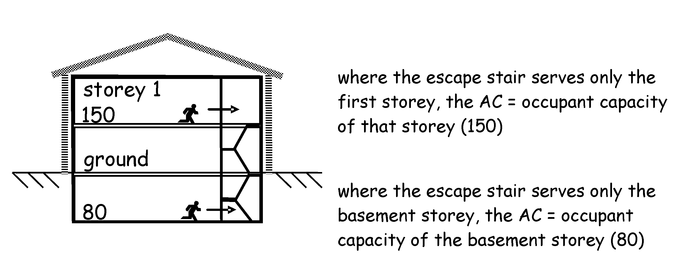
In a building in which the escape stair serves more than 1 storey the appropriate capacity for each storey should be calculated and the total appropriate capacity for all the storeys served by the escape stair should then be used in the formula for calculating the effective width of the escape stair. A deduction of 20% from the appropriate capacity is allowed for the number of occupants who could be standing in the stair.
This method of calculating the escape stair width can be used to reduce the width of the stair as it rises up the building although this would not be a typical form of construction.
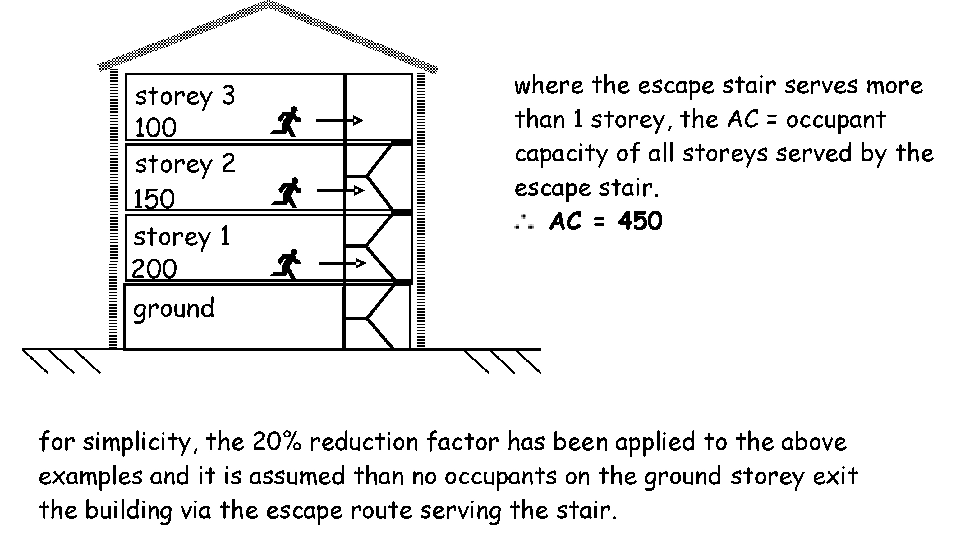
Phased evacuation allows occupants most at risk to be evacuated first. This allows the designer to reduce the width of the escape stairs and minimises disruption in large buildings. Tall buildings take longer to evacuate and where the building is at a height of more than 25m it is beyond the reach capability at which Fire and Rescue service can effect external rescue. Therefore, when phased evacuation is adopted in buildingsadditional active and passive fire protection measures will be necessary.
As phased evacuation relies on some occupants remaining where they are until instructed to leave, it is only suitable for buildings where the occupants are awake and familiar with the building, for example, offices.
The occupants first evacuated are those on the storey of fire origin and those on the storey immediately above. If further evacuation is required this is done on the basis of the next two adjoining upper storeys to avoid congestion in the escape stairs. The remaining storeys would then be evacuated two storeys at a time however this would be dependent on the severity of the fire and any direction given by the fire and rescue service.
Because of the additional time it may take to evacuate a building or part of a building where the means of escape is based on vertical phased evacuation, the following fire safety measures should be provided:
•installation of an automatic fire detection and alarm system to BS 5839: Part 1: 2002, Category L2, and
•a voice alarm should be installed in accordance with BS 5839: Part 8: 2008. Such a system enables two or more stages of alarm to be given within a particular area, and
•the escape stairs should be entered from a protected lobby, and
•every storey should be a compartment storey, and
•if the building has any storey at a height of more than 25m, every storey should be protected by an automatic life safety fire suppression system (see guidance to Standard 2.15), and
•an internal speech communication system should be provided via a control point at the access level to allow the fire and rescue service to converse with a fire warden on every storey.
In a building where the stairs have been designed on the basis of vertically phased evacuation the appropriate capacity [AC] in relation to an escape stair at any storey above or below the adjacent ground is calculated by the following method and in accordance with the diagram below.
In a building, or part of a building, which is divided by one or more compartment floors, the appropriate capacity [AC] is equal to, the total occupancy capacity, less 20%, of each of the 2 adjacent upper storeys, served by the escape stair, or in the case of an escape stair serving a basement storey, the 2 adjacent basement storeys served by that escape stair, having in either case the greatest combined occupancy capacity.
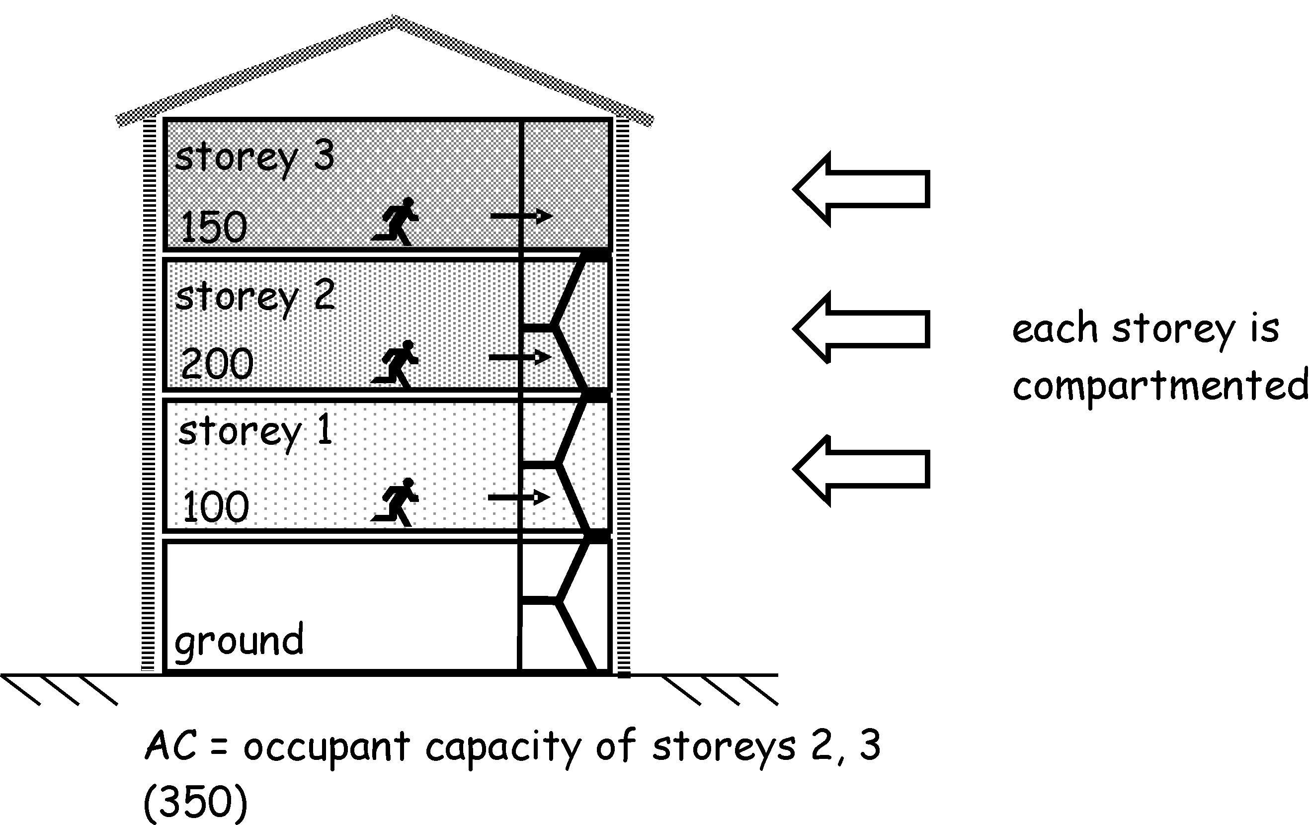
Calculation of effective width - based on the above principles for simultaneous and phased evacuation, the effective width of every escape stair in mm can be calculated by the following formula:
EW = 5.3 x AC N − 1 EW = {5.3 x AC} over {N - 1}
Where:
•EW is the effective width of an escape stair measured in mm between handrails and clear of obstructions
•AC is the appropriate capacity, which in relation to an escape stair is the occupancy capacity of the storey served by the escape stair, less 20%
•N - 1 is the number of escape stairs minus 1, unless it meets exception for protected lobbies above
A deduction of 20% from the appropriate capacity is made to allow for the number of occupants who could be standing in the stair.
Before using the formula it is necessary to consider the possibility that one stair may be affected by fire or smoke before all occupants have evacuated the building. For that reason one stair should be discounted for calculation purposes, unless a protected lobby is provided on every storey between each escape stair in a protected zone and any part of the building at any storey from which there is access to the escape stair.
If the escape stair contains any of the rooms listed in clause 2.9.24 the stair should be discounted from the stair width calculation.
Example 1 - simultaneous evacuation
What is the minimum effective width needed for escape stairs in an office building with 4 storeys and 2 escape stairs and which escape is based on simultaneous evacuation? For this example it is assumed that the occupants are distributed evenly across each storey, therefore the number of occupants will be split evenly to each escape stair.
There are 100 occupants on the top storey, 150 occupants on the 2nd storey and 200 occupants on the 1st storey. The escape routes on the ground storey do not communicate with the escape stairs.
It is assumed that the buildings do not have any protected lobbies, therefore the effective width equals:
EW = 5.3 x AC N − 1 EW = {5.3 x AC} over {N - 1}
AC is the appropriate capacity and is the sum of the occupancy capacity of the storeys served by the escape stair minus 20% for standing capacity in the stair:
Top storey = 100 x 0.8
2nd storey = 150 x 0.8
1st storey = 200 x 0.8
AC = 360
EW = 5.3 x 360 2 − 1 EW = {5.3 x 360} over {2 - 1}
= 1908 1 {1908} over {1}
The minimum width of each escape stair will be 1908mm.
Example 2 - simultaneous evacuation
What is the minimum effective width needed for escape stairs in an office building with 6 storeys and 3 escape stairs and which escape is based on simultaneous evacuation. For this example it is assumed that the occupants are distributed evenly across each storey, therefore the number of occupants will be split evenly to each escape stair.
Each storey has 300 occupants and the escape routes on the ground storey do not communicate with the escape stairs.
It assumed access to each protected zone containing the escape stair is by way of a protected lobby. Therefore, there is no need to deduct 1 stair from the calculations:
EW = 5.3 x AC N EW = {5.3 x AC} over {N}
AC is the appropriate capacity and is the sum of the occupancy capacity of the storeys served by the escape stair minus 20% for standing capacity in each of the stairs.
There are 5 storeys accessing the escape stair and each storey has 300 occupants the appropriate capacity is found by:
AC = 300 x 5 x 0.8
AC = 1200
EW = 5.3 x 1200 3 EW = {5.3 x 360} over {2 - 1}
= 6360 3 {1908} over {1}
The minimum width of each escape stair will be 2120mm.
Example 3 - phased evacuation
What is the minimum effective width needed for escape stairs in an office building with 10 storeys and 3 escape stairs and which escape is based on phased evacuation. For this example it is assumed that every storey is a compartment storey and that the occupants are distributed evenly across each storey, therefore the number of occupants will be split evenly to each escape stair.
Each storey has 300 occupants and the escape routes on the ground storey do not communicate with the escape stairs.
As escape is based on phased evacuation, access to each protected zone containing the escape stair should be by way of a protected lobby. Therefore, there is no need to deduct 1 stair from the calculations:
EW = 5.3 x AC N EW = {5.3 x AC} over {N}
AC is the appropriate capacity of each of the 2 adjacent upper storeys, with the greater occupancy capacity, minus 20% for standing capacity in each of the stairs:
AC = (300 x 0.8) + (300 x 0.8)
AC = 480
EW = 5.3 x 480 3 EW = {5.3 x 360} over {2 - 1}
= 2544 3 {1908} over {1}
EW = 848mm
However as the effective width of each escape stair should be at least 1200mm all 3 stairs should be at least 1200mm wide.
Combined escape routes - where escape routes from a storey consist of a combination of escape stairs and other escape routes (see diagram below) the effective width of any escape stair from that storey should be designed to take into account that proportion of the number of occupants on that storey who may escape by way of the other escape routes.
The escape route should be sized to take account of all the occupants who will be escaping. Therefore, where the escape route from an escape stair is also the escape route from the ground storey and/or basement storey, the width of that escape route should be increased to take account of that proportion of the occupancy capacity from the ground storey and/or basement storey.
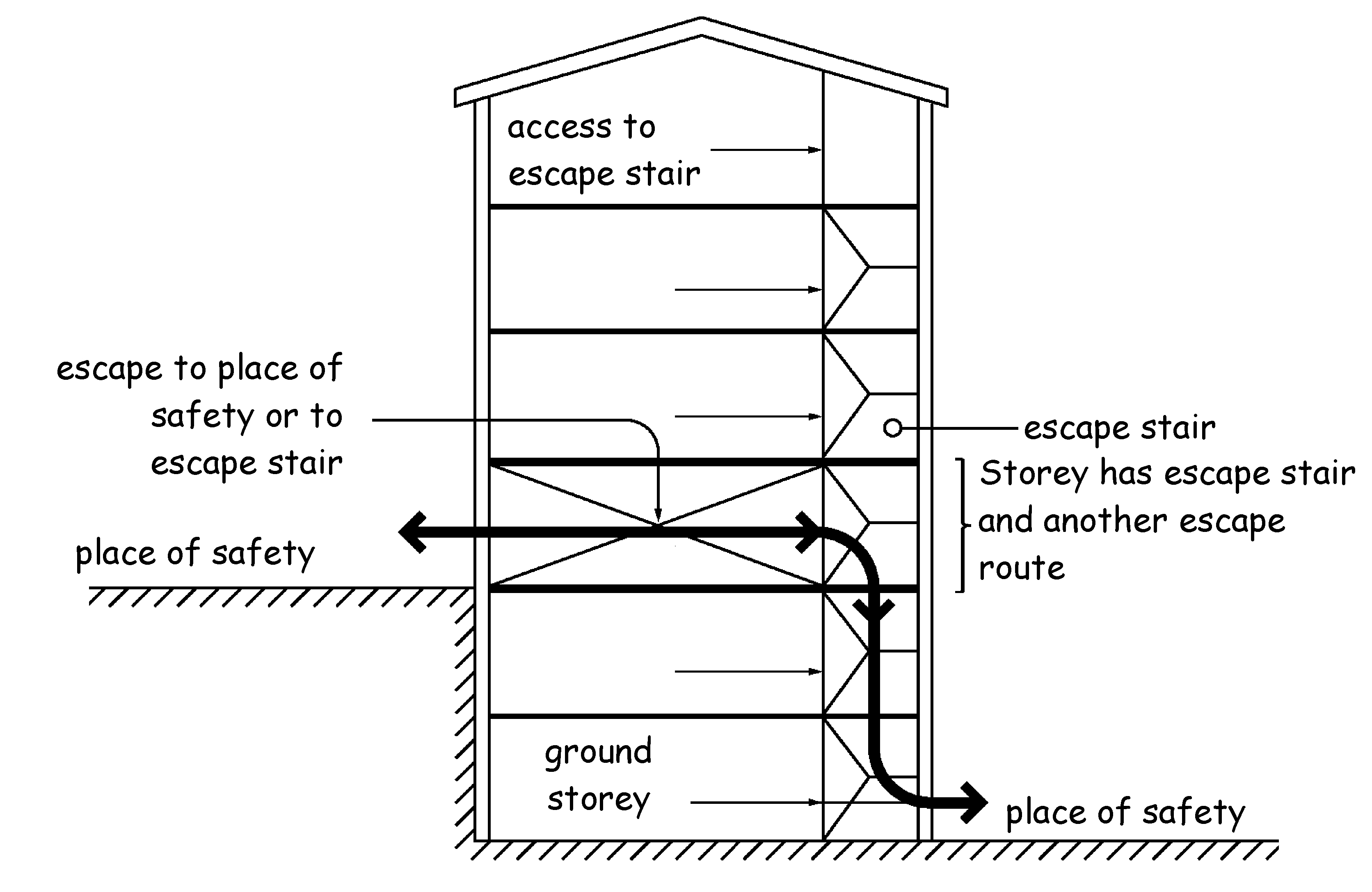
2.9.32 Independence of escape stairs
Where there are alternative escape stairs from a storey, there is the risk that one of the escape stairs could be smoke logged preventing access through to the alternative escape stair. Where a room or storey needs two or more escape stairs, it should be possible to reach 1 alternative escape stair without passing through the other.
When the escape stairs are adjacent to one another, to reduce the likelihood of them becoming smoke logged at the same time, for example, where the protected zones enclosing escape stairs share a common wall, any access between them should be by way of a protected lobby.
2.9.33 Escape routes in a central core
To reduce risk of smoke spread to more than 1 escape stair, corridor or lobby, a building with more than 1 escape route contained in a central core, should be planned so that the exits from the storey are remote from one another, and so that no 2 exits are approached from the same lift hall, common lobby or undivided corridor or linked by any of these other than through self-closing fire doors.
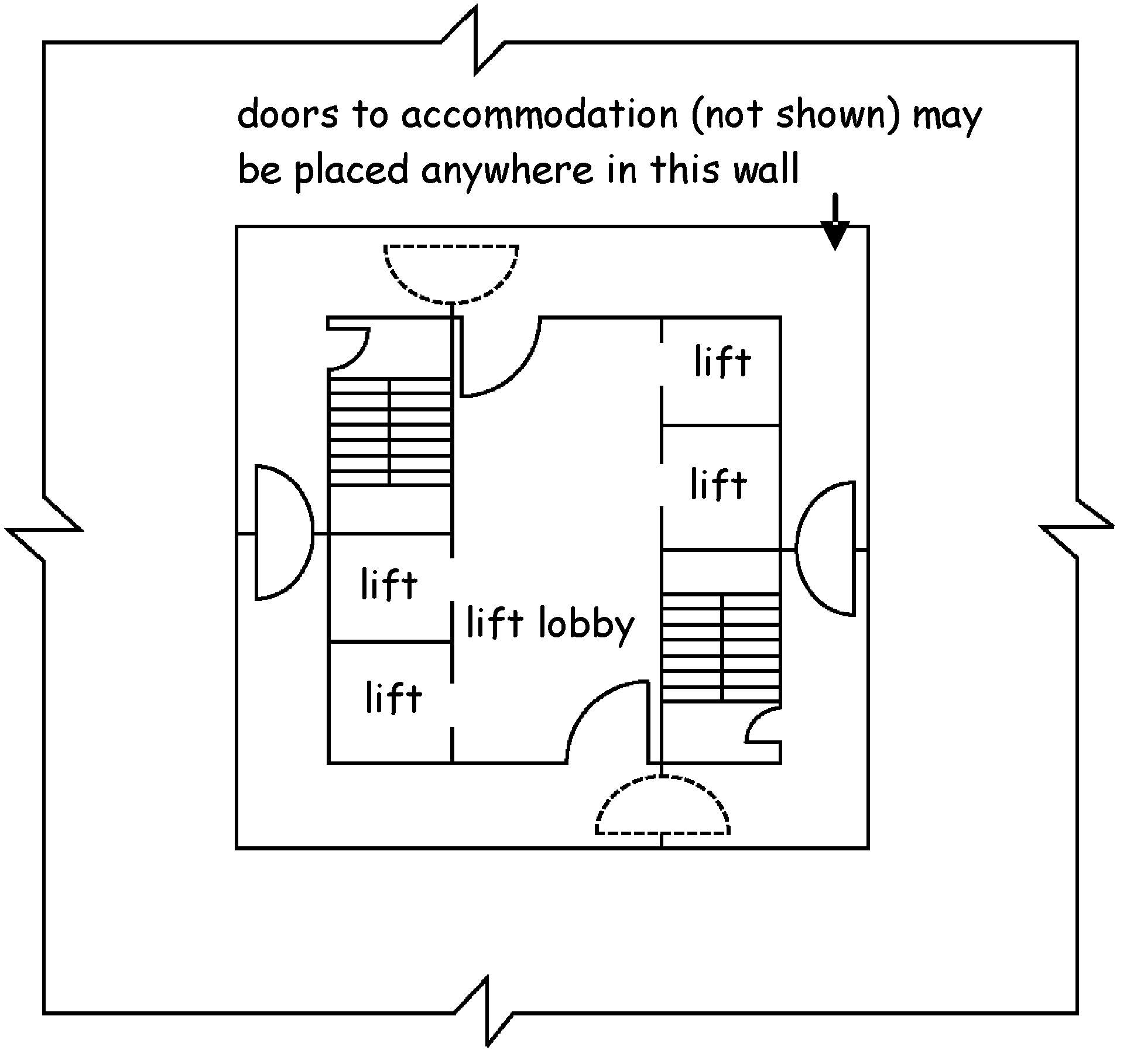
2.9.34 Escape stairs in basements
The limited natural ventilation available in a basement can lead to rapid heat and smoke build up. The heat and smoke generated can be forced up through any opening such as a door into a stairway. This means that fire-fighting in under-ventilated compartments must be approached with caution before opening the door to the basement storey.
There is also a risk that disoriented occupants could continue their escape to the basement storey instead of escaping through the ground storey.
In order to minimise these risks, a wall or screen (including a self-closing fire door) with a medium fire resistance duration should be provided between the ground storey of the protected zone and the basement storey.
2.9.35 Construction of escape stairs
In buildings of more than 1 storey where the means of escape is via an escape stair, this will also be the route from which the fire and rescue services will fight the fire and effect rescue. The possibility that the escape stair may be affected by fire breaking out or being deliberately set in the stairway has to be considered. Consequently the escape stair should be provided with additional protection.
Therefore, every part of an escape stair (including landings) and the floor of a protected zone or protected lobby, should be constructed of non-combustible material. However this does not apply to:
•an escape stair in shared residential accommodation
•any handrail, balustrade or protective barrier on an escape stair
•an escape stair which connects 2 or more levels within a single-storey where the difference in height between the highest and lowest level is not more than 1.8m
•an escape stair from a gallery, catwalk or openwork floor constructed in accordance with the guidance in clause 2.9.25
•a floor finish (e.g. laminate flooring) applied to the escape stair (including landings) or to the floor of a protected zone or protected lobby.
2.9.36 External walls adjacent to protected zones
If a protected zone has an external wall that projects beyond the face of a building or is set back in a recess, the protected zone may be vulnerable to fire following the break out of fire through an adjacent window, door or other opening. Radiated heat or flames from the fire may impede occupants using the protected zone to escape.
Therefore where any part of a protected zone is not more than 2m from, and makes an angle of not more than 135° with any part of an external wall of another part of the building, the escape stair should be protected against fire for a distance of 2m, by construction with a:
•short fire resistance duration where every storey in the building is at a height of not more than 7.5m above the ground, or
•medium fire resistance duration where any storey is at a height of more than 7.5m.
The designer can choose which wall should be fire resisting and may include fire resisting facades or other fixed glazing, or any other opening protected against fire. However it is not sufficient to use the final exit door as a barrier between the occupants escaping and the fire. In such cases the external wall adjoining the protected zone at the final exit should be protected against fire as described above.
2.9.37 External routes of escape
Escape routes will normally lead to the final exit door of the building, which leads to a safe place in the outside air from which occupants can freely disperse. An exit can also lead to an external escape stair, a flat roof or access deck giving access to a place of safety.
Protection of external route of escape - in some cases it may not be possible to freely disperse away from the building (e.g. where the final exit door discharges to an enclosed outdoor space). In such cases, where there is only 1 route of escape, the external wall of the building within 2m of the route of escape should have a short fire resistance duration for integrity up to 1.1m above the adjoining ground. This does not apply to sub-floor vents.
An external escape stair is an unenclosed escape stair, which is open to the external air and provides occupants with an escape route, which leads to a place of safety. They present additional hazards to occupants evacuating a building in the event of fire. This is because the escape stair will be exposed to the possible effects of inclement weather and occupants who are unfamiliar with the escape routes can feel less confident using an unenclosed stair high above the ground.
Therefore, an external escape stair should only serve a building where:
•the top most storey height is not more than 7.5m, and
•the building or part of the building is not accessible to the general public, and
•in the case of a residential care building or a hospital, the stair is intended to be used by staff only.
In order to protect the occupants from fire and smoke during evacuation, the external escape stair should be protected against the outbreak of fire from within the building. Where the escape stair which has a total rise of more than 1.6m, every part of the external wall including fixed windows or glazing, self-closing fire doors (other than a door opening from the top storey) or any other opening not more than 2m from the escape stair, should have a short fire resistance duration. Fire protection below an escape stair should be extended to the lowest ground level.
An external escape stair with a total rise of not more than 1.6m from which occupants can freely disperse, is considered to be low enough above the ground to present minimal risk to occupants leaving the building and as a result, fire protection need not be provided.
Due to the likely smoke dissipation to atmosphere; service openings including ventilation ducts not more than 2m from the escape stair may be protected by heat activated sealing devices or systems.
Escape across flat roofs and access decks can be hazardous because the surface can be exposed to adverse weather conditions and in the case of flat roofs, may also have obstructions or no edge protection. Therefore, escape routes over flat roofs should only be used where the building or part of the building is inaccessible to the general public and there is more than 1 escape route from the room or storey leading to the flat roof.
In order to protect occupants from fire, a flat roof or an access deck forming part of an escape route should have medium fire resistance duration for the width of the escape route and for a further 3m on either side of the escape route. Every wall not more than 2m from either side of the escape route, should have a short fire resistance duration up to a height of at least 1.1m measured from the level of the escape route.
In addition, there should be no exhausts of any kind less than 2m from the escape route unless protected by heat activated sealing devices or systems (see clause 2.1.14). A wall or protective barrier at least 1.1m high may be necessary on each side of the escape route or along the edge of the access deck when the escape route is across a flat roof or access deck (see Section 4 Safety).
2.9.38 Final exits
The final exit to a place of safety at ground level, should present as little restriction as possible to occupants using wheelchairs or having other disabilities. Final exits should therefore be provided with:
•a level platt except for any nominal slope for drainage having an area of at least 1.2m x 1.2m, and
•a threshold that does not form a trip hazard and will permit unassisted egress to occupants in a wheelchair (see Section 4 Safety).
When altering existing buildings, it may not always be reasonably practicable to achieve the above recommendations.
2.10 Escape lighting
#Source page 32
Mandatory Standard
| Standard 2.10 Every building must be designed and constructed in such a way that in the event of an outbreak of fire within the building, illumination is provided to assist in escape. |
2.10.0 Introduction
Escape routes should be illuminated to aid the safe evacuation of a building in an emergency.
Emergency lighting and exit signage may be necessary under the Fire Safety (Scotland) Regulations 2006 (see clause 2.0.8).
Reference should be made to Part 1 of the Cinematography (Safety) (Scotland) Regulations 1955 for buildings such as cinemas where there are specific requirements for lighting.
Due to the special fire precautions within residential care buildings, hospitals and enclosed shopping centres, additional guidance is grouped in the annexes. The intention is to help designers and verifiers find the information they require quickly when designing or vetting such buildings. However it is important to remember that the guidance in the annexes is in addition and supplementary to the guidance to Standard 2.1 to 2.15. For additional guidance on:
•residential care buildings, see annex 2.A
•hospitals, see annex 2.B
•enclosed shopping centres, see annex 2.C.
Conversions - in the case of conversions, as specified in regulation 4, the building as converted shall meet the requirement of this standard (regulation 12, schedule 6).
2.10.1 Escape route lighting
Escape route lighting utilises the artificial lighting within the building, but should be supplied by a fire protected circuit.
Every part of an escape route should have artificial lighting supplied by a protected circuit that provides a level of illumination not less than that recommended for emergency lighting. Where artificial lighting serves a protected zone, it should be via a protected circuit separate from that supplying any other part of the escape route.
Artificial lighting supplied by a protected circuit need not be provided if a system of emergency lighting is installed.
2.10.2 Protected circuits
A protected circuit is a circuit originating at the main incoming switch or distribution board, the conductors of which are protected against fire. Regardless of what system is employed, escape routes should be capable of being illuminated when the building is in use. In conversions for example, it may be easier to install self-contained emergency luminaires than to install a protected circuit to the existing lighting system.
2.10.3 Emergency lighting
Emergency lighting is lighting designed to come into, or remain in, operation automatically in the event of a local and general power failure. It should be installed in buildings considered to be at higher risk, such as in high rise buildings, buildings with basements or in rooms where the number of people is likely to exceed 60.
Emergency lighting should be installed in buildings or parts of a building considered to be at higher risk such as:
a.in a protected zone and an unprotected zone in a building with any storey at a height of more than 18m
b.in a room with an occupancy capacity of more than 60, or in the case of an inner room, the combined occupancy capacity of the inner room plus the adjoining room (and any protected zone or unprotected zone serving these rooms) is more than 60
c.in an underground car park including any protected zone or unprotected zone serving it where less than 30% of the perimeter of the car park is open to the external air
d.in a protected zone or unprotected zone serving a basement storey
e.in a place of special fire risk (other than one requiring access only for the purposes of maintenance) and any protected zone or unprotected zone serving it
f.in a protected zone or unprotected zone serving a storey which has at least 2 storey exits in the following buildings:
Emergency lighting in places of entertainment such as, cinemas, bingo halls, ballrooms, dance halls and bowling alleys, should be in accordance with BS 5266: Part 1: 2005. Emergency lighting in any other building should be in accordance with BS 5266: Part 1: 2005 as read in association with BS 5266: Part 7: 1999 (BS EN 1838: 1999).
In the case of a building with a smoke and heat exhaust ventilation system, the emergency lighting should be sited below the smoke curtains or installed so that it is not rendered ineffective by smoke filled reservoirs.
2.11 Communication
#Source page 33
Mandatory Standard
| Standard 2.11 Every building must be designed and constructed in such a way that in the event of an outbreak of fire within the building, the occupants are alerted to the outbreak of fire. |
2.11.0 Introduction
It is important that any outbreak of fire in premises is detected at an early stage in order that the occupants once alerted can commence evacuation of the premises as soon as possible. There should also be a means so that anyone in the building who discovers a fire, can alert others to the existence of the fire and this should include arrangements for calling the fire and rescue service. The benefit of early warning of a fire will increase the probability of the safe evacuation of the building and will assist owners and occupiers of buildings in formulating their fire safety policy and emergency fire action plan.
Risk assessment fire warning - in small single storey non-residential buildings the means of raising the alarm could be quite simple, e.g. where a shouted warning "FIRE" by the person discovering the fire may be all that is needed. In more complex buildings, a sophisticated fire detection and fire alarm system may be needed.
False alarms - around 97% of all automatic calls received by the fire and rescue service result in unnecessary attendance due to false alarms. This is normally attributed to poor, design, installation or maintenance of automatic fire detection and alarm systems. Guidance on how to assess the risks and reduce false alarms is provided in BS 5839: Part 1: 2002.
Special fire precautions are necessary within residential care buildings, hospitals and enclosed shopping centres and additional guidance is provided in the annexes. The intention is to help designers and verifiers find the information they require quickly when designing or vetting such buildings. It is important to remember that the guidance in the annexes is in addition and supplementary to the guidance to Standard 2.1 to 2.15. For additional guidance on:
•residential care buildings, see annex 2.A
•hospitals, see annex 2.B
•enclosed shopping centres, see annex 2.C.
Conversions - in the case of conversions, as specified in regulation 4, the building as converted shall meet the requirement of this standard (regulation 12, schedule 6).
2.11.1 Evacuation methods
Evacuation methods affect the category of fire detection and fire alarm system that should be installed in a particular building. The type of occupancy and means of escape strategy should be determined at building design stage. For example evacuation may be:
•simultaneous, where all occupants evacuate the building at the same time
•phased, where some occupants evacuate parts of the building before others, or
•progressive horizontal evacuation, where occupants leave the compartment of fire origin to adjacent compartments leading to a storey exit.
Where the design of the means of escape is based on simultaneous evacuation of all occupants, then operation of a manual call point or fire detector should give an almost instantaneous warning from all the fire alarm sounders. However where the means of escape is based on phased evacuation, then a staged alarm system is appropriate. This enables two or more stages of alarm to be given within a particular area (e.g. alert or evacuate signals).
Building uses incorporating design for phased evacuation are often a fire engineered solution which will include the fire alarm specification. Dependant on the determined use at design stage, a category L1 to L5 with or without voice alarm should be installed.
The factors that should be considered when assessing what category of fire alarm or automatic fire detection system is to be provided, will vary widely from one premises to another therefore the type of system will need to be considered on a case by case basis.
2.11.2 Assessment of the determined use
An assessment of the determined use should be carried out at the design stage, taking into account the building evacuation factors in order to specify the appropriate alarm category for the circumstances concerned. The significance of various evacuation factors will depend on use and occupancy. These factors are:
•whether occupants are awake and alert or asleep
•are they familiar or not with the building
•the complexity of the building
•the number of occupants
•the type of activity, and
•evacuation method.
In any building, some of the occupants may have impaired sensory, cognitive and/or mobility impairments which could create difficulties in perceiving or responding to a fire or in evacuating the building.
Compensatory features - buildings in which other fire precautions, such as means of escape, depart from the Technical Handbook guidance should have in place fire alarms systems to compensate for such departures. Category, L1, L2, L3, L4, or L5 systems should therefore be installed in the building.
2.11.3 Categories of fire detection and fire alarm system
Fire detection and fire alarm system is a term used in this handbook to describe any type of automatic sensor network and associated control and indicating equipment. Sensors may be sensitive to smoke, heat, gaseous combustion products or radiation. Normally the control and indicating equipment operates a fire alarm system and it may perform other signalling or control functions as well. Automatic sprinkler systems may also be used to operate a fire alarm system.
At the design stage it is important to take into account the building evacuation factors, in order to specify the alarm category. Life safety fire alarm systems installed in a building will be one or more of the following categories.
Category L systems are automatic fire alarm systems installed for the protection of life, incorporating detectors, sounders and manual call points installed in the building. Category L fire alarm systems are sub-divided from the most stringent L1 to the least stringent requirement L5, depending on the detector coverage in the building:
•L1 detectors are installed throughout the building; the objective of a category L1 system is to offer the earliest possible warning of fire, so as to achieve the longest available time to escape
•L2 detectors are installed in the building so as to give warning before escape routes are impassable owing to the presence of fire, smoke or toxic gases; but with enhanced coverage in specified areas of the building
•L3 detectors are installed so as to give a warning of fire at an early enough stage to enable all occupants, other than possibly those in the room of fire origin, to escape safely, before the escape routes are impassable owing to the presence of fire, smoke or toxic gases
•L4 detectors are installed in those parts of the escape routes comprising circulation areas and circulation spaces, such as corridors and stairways
•L5 detectors, sounders are installed in specified locations where the designed is to satisfy a specific fire safety objective (other than that of a category L1, L2, L3 or L4 system).
Categories L1 to L5 should be installed in accordance with BS 5839: Part 1: 2002 which specifies various categories of life safety fire alarm systems.
Category M is a standalone manual fire alarm system that includes manual call points and sounders at specific locations in the building. Automatic detection is not part of the system. Nevertheless category M systems should be installed in conjunction with L1, L2, L3, L4, L5 and voice alarm systems.
BS EN 54: Part 11: 2001 covers two types of call points. Type A (direct operation) in which the change to the alarm condition is automatic (i.e. without the need for further manual action) when the frangible element is broken or displaced and Type B (indirect operation) in which the change to the alarm condition requires a separate manual operation of the operating element by the user after the frangible element is broken or displaced.
Manual call points as specified in BS EN 54: Part 11: 2001 (Type A) should be installed in buildings and sited in accordance with BS 5839: Part 1: 2002.
Voice alarms - in complex and multi use buildings the installation of a voice alarm should be considered. For example, where a building is designed for phased evacuation or where occupants might not respond quickly to a fire warning, or where occupants are unfamiliar with the fire warning arrangements. Voice alarms systems may be used to alert staff or give a coded message explicit to those having responsibility for taking action in a fire. They can form part of a public address system and give both an audible signal and verbal instructions (which may be pre-recorded) in the event of fire. A voice alarm system should be installed to comply with BS 5839: Part 8: 2008.
The fire warning signal should be distinctive in sound from other sounds which may be in general use and be accompanied by clear verbal instructions.
In some circumstances visual alarm signals should be used to either supplement or replace the audible alarm, such as where hearing protection is likely to be used or in situations where occupants have a hearing impairment. Buildings such as hospitals and residential care buildings for example may incorporate a combination of audible, visual and voice alarm in the overall system.
2.11.4 Residential care buildings
A residential care building should have a communication system designed and installed in accordance with the guidance set out in annex 2.A. This is to give occupants and staff the earliest possible warning of an outbreak of fire and allow time for assisting occupants in an emergency to evacuate the building or for horizontal progressive evacuation initially to an adjacent compartment which leads to a compartment exit.
2.11.5 Hospitals
A hospital should have a communication system designed and installed in accordance with the guidance set out in annex 2.B. This is to give occupants and staff the earliest possible warning of an outbreak of fire and allow time for assisting occupants in an emergency to evacuate the building or for horizontal progressive evacuation initially to an adjacent sub-compartment which leads to a compartment exit.
2.11.6 Shared residential accommodation
Shared residential accommodation is designed to provide sleeping accommodation for not more than 10 persons, entered from open air at ground level and having no sleeping accommodation at a storey height of more than 7.5m. At least a category LD2 (Grade D) should be installed.
2.11.7 Residential buildings (other than residential care buildings and hospitals)
The threat posed by a fire in Residential buildings such as hotels and boarding houses in which occupants may be asleep, is much greater than that in buildings where the occupants are normally awake and alert. Guests may not be aware that their lives are at risk and are also likely to be unfamiliar with their accommodation or escape routes.
A category L2 system is likely to be appropriate for the majority of sleeping accommodation premises. However it is important that the choice of system category is based on a risk assessment of the particular circumstances.
Early warning of fire significantly increases the degree of safety provided to occupants. In order to minimise false alarms, a variation from the category L1 system may be justified regards the siting of smoke or carbon monoxide detectors in bedroom areas. Detectors are typically installed in most other rooms and few if any areas should be left unprotected and a category L1 or L2 system should be installed.
2.11.8 Entertainment buildings and assembly buildings
The occupants will be alert but could be unfamiliar with the building; nevertheless they should be able to respond to an outbreak of fire in their immediate area. Certain events, such as some pop concerts, may attract large numbers of young, excitable persons and will require a greater degree of control and stewarding than for other events which, despite attracting similar audience numbers, will have an entirely different behaviour profile, such as a play performed in a large theatre.
A category L1, L2, L3, or M system, should be installed in the building. The category will be dependant on the use of the building, for example whether it is a cinema, restaurant or nightclub, an assessment should be carried out at the design stage to determine the appropriate category. The following is a guide only.
Where there are:
•more than 300 occupants then a category L1 system should be installed
•no more than 300 occupants but more than 100 then at least a category L2, system should be installed
•no more than 100 occupants but more than 60 then at least a category L3 system should be installed, and
•no more than 60 then at least a category M system should be installed.
2.11.9 Offices and shops
In shops, the occupants will be alert but could be unfamiliar with the premises however they should be able to respond to an outbreak of fire in their immediate area. In department stores with restaurants or cafeteria a phased evacuation can be used where fire safety measures are provided to facilitate this strategy. A category M, L3 or L4 system should be installed, in shops where there are:
•more than 300 occupants then a category L3 system should be installed
•where the building is in different occupation then a category L3 system should be installed
•not more than 300 occupants but more than 100 then a category L4 system should be installed, and
•not more than 100 occupants then a category M system should be installed.
In offices, the occupants will be alert and familiar with the building and are unlikely to be so engaged with the task at hand that they initially fail to perceive or respond to an outbreak of fire in their immediate area. In these circumstances, a manually operated category M system that can be heard throughout the building when operated from a manual call point may be all that is required.
2.11.10 Educational building
Many educational buildings are also a community resource and serve a variety of functions. It is therefore important that the choice of system category is based on risk assessment of the particular circumstances. An example would be where a country school could consist of one large classroom with 14 pupils and a teacher, where the warning is understood, and can be heard throughout the building. More complex educational buildings, may contain different uses such as large assembly areas, auditoriums, or administration centres. In such cases, the guidance under the relevant building types should also be followed. In educational buildings with more than 60 occupants therefore, at least a category M, L3, L4 or L5 system should be installed dependant on assessment at the design stage.
2.11.11 Factory buildings and storage buildings
In factory buildings (class 1), factory (class 2), storage buildings (class 1) and storage buildings (class 2) the occupants will be alert and will be familiar with the building, also the numbers of persons in the building will normally be low but can vary for example a large compartment with production lines such as clothes manufacturing. Due to the varied nature of use, some buildings may contain hazardous or dangerous materials or processes, with the potential for fire or explosion, posing an additional risk to persons, on or in the immediate vicinity of the building. Such factors should be part of the fire risk assessment to ensure that fire safety measures are provided to safeguard occupants who are so engaged with the task at hand that they may initially fail to perceive or respond to an outbreak of fire in their immediate area.
Normally a category M system should be installed, however occupants could work alone in remote areas of the building and this should be considered when determining the category of system.
Therefore dependant on assessment at design stage a category M, L1, L2, L3, L4, or L5 should be installed.
2.11.12 Enclosed shopping centres
An enclosed shopping centre should have a communication system designed and installed in accordance with the guidance set out in annex 2.C.
2.11.13 Transportation Terminals
These buildings may be small single-storey or large complex buildings which include mixed use occupancy such as airports, where the category of alarm system will normally form part of a fire engineering solution. Excluding large complex buildings and dependant on risk assessment at design stage, a category M, L4 or L5 system should be installed.
2.11.14 Other non-residential buildings
In small single-storey buildings where the occupant number is not more than 10 and the floor area is such that everyone can see each other, a shouted warning "FIRE" by the person discovering the fire could be all that is needed. In assessing the situation, it must be determined that the warning can be heard and understood throughout the building, or compartment, including those in remote locations such as toilets.
2.12 Fire and rescue service access
#Source page 34
Mandatory Standard
| Standard 2.12 Every building must be accessible to fire and rescue service. |
2.12.0 Introduction
Vehicle access to the exterior of a building is needed to enable high reach appliances, such as turntable ladders and hydraulic platforms, to be used, and to enable pumping appliances to supply water and equipment for fire-fighting and rescue activities. The access arrangements increase with building size and height.
Conversions - in the case of conversions, as specified in regulation 4, the building as converted shall meet the requirements of this standard in so far as is reasonably practicable, and in no case be worse than before the conversion (regulation 12, schedule 6).
2.12.1 Vehicle access provision
Access from a public road should be provided to assist fire and rescue personnel in their rescue and fire-fighting operations. Whilst the access will depend to some extent on the vehicles and equipment used, assistance may be provided from adjoining fire and rescue services when the need arises. For this reason, the more demanding guidance for high reach appliances may be recommended by the fire and rescue service. This may have a significant impact on planning and a feasibility study may be appropriate. Consultation with the fire and rescue service at the earliest opportunity is strongly recommended.
Vehicle access should be provided to at least one elevation of all buildings to assist in fire-fighting operations. The vehicle access route should be provided to the elevation or/and rescue elevations where the principal entrance, or entrances, are located.
Vehicle access is recommended to other elevations of a building where:
•the building is a hospital, or
•the area of any compartment in a non-domestic building is more than 900m2, or
•the building footprint has a perimeter more than 150m.
However vehicle access routes to more than one elevation may not always be possible due to the constraints of the site, and pedestrian access for fire and rescue service personnel, as described in clause 2.12.4, may be sufficient.
To assist fire and rescue service personnel to connect a short length of hose between the pumping appliance and dry/wet riser inlets (see guidance to Standard 2.14) quickly and efficiently, parking spaces should be provided at a distance not more than 18m from riser inlets.
2.12.2 Vehicle access routes
Access routes to buildings for fire and rescue service vehicles or personnel should not be assessed in isolation and the proposed vehicle access routes will in effect, be dictated by need for water hydrants and fire mains (see clause 2.14.7).
Dead end route - fire and rescue service vehicles should not have to reverse more than 20m from the end of an access road. Where any dead-end route is more than 20m long, turning facilities should be provided. This can be a turning circle or a hammerhead designed on the basis of the diagram and table below:
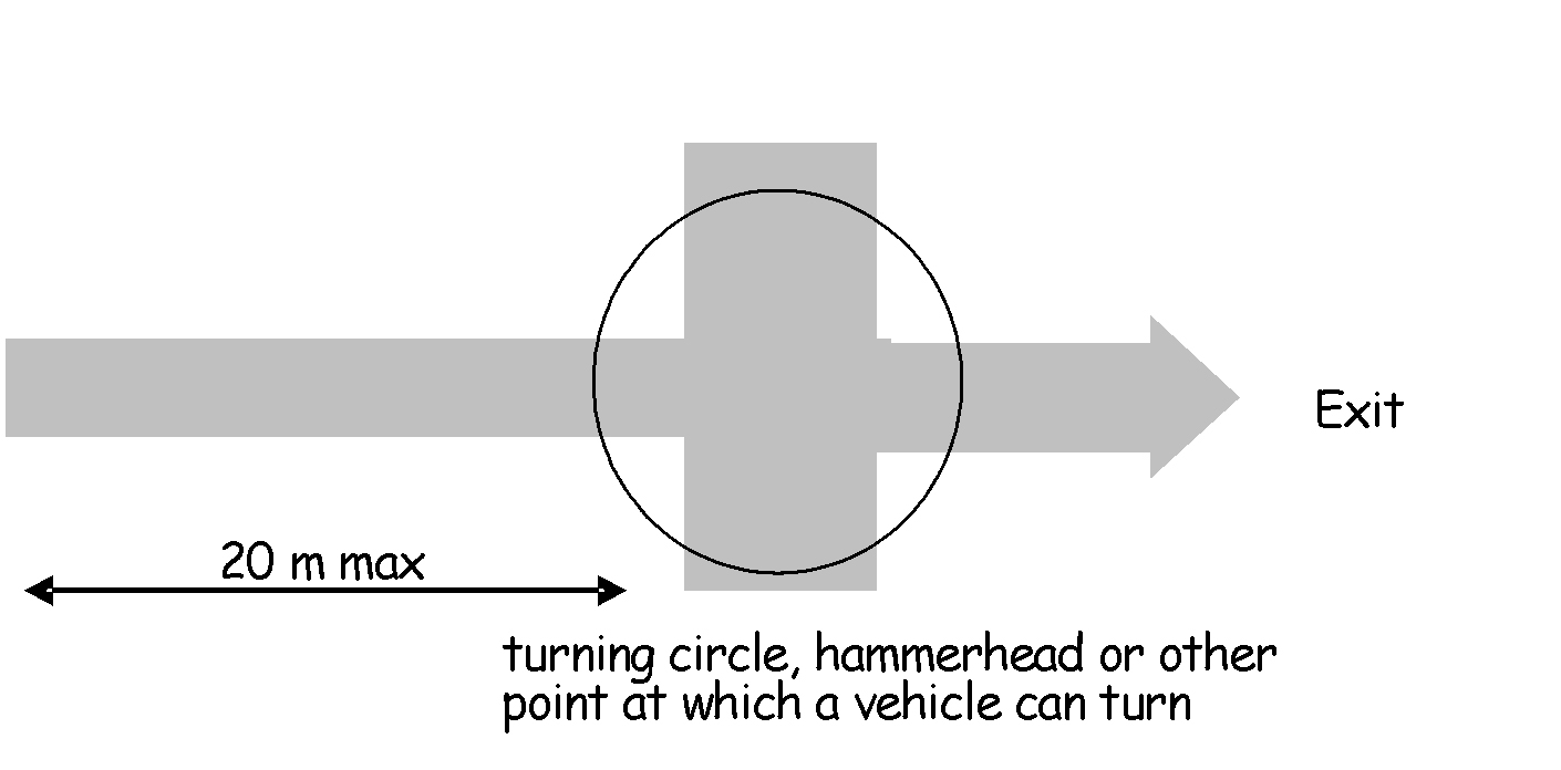
Table 2.15. Access route for fire and rescue service vehicles
| Access | High reach appliance | Pumping appliance only [1] |
|---|---|---|
| Minimum width of road between kerbs | 3.7m | 3.7m |
| Minimum width of gateways etc | 3.5m | 3.5m |
| Minimum clearance height | 4.0m | 3.7m |
| Minimum turning circle between kerbs | 26.0m | 16.8m |
| Minimum turning circle between walls | 29.0m | 19.2m |
| Minimum axle loading | 14 tonnes | 14 tonnes |
Additional information:
1.Where, in consultation with the fire and rescue service, access is needed for pumping appliances only, the smaller dimensions may be used.
2.12.3 Operating spaces for high reach appliances
Following consultation with the fire and rescue service, if it is recommended that an operating space, or spaces, for a high reach appliance should be provided, the operating space(s) should:
•have a ground loading capacity of not less than 8.3kg/m2, and
•be level or not have a gradient more than 1 in 12.
The operating space shown in the diagram below is suitable for either a hydraulic platform or turntable ladder.
Where a building has obstructions such as balconies or other projections, the building line should be taken to be the outer edge of the balconies or other projections.
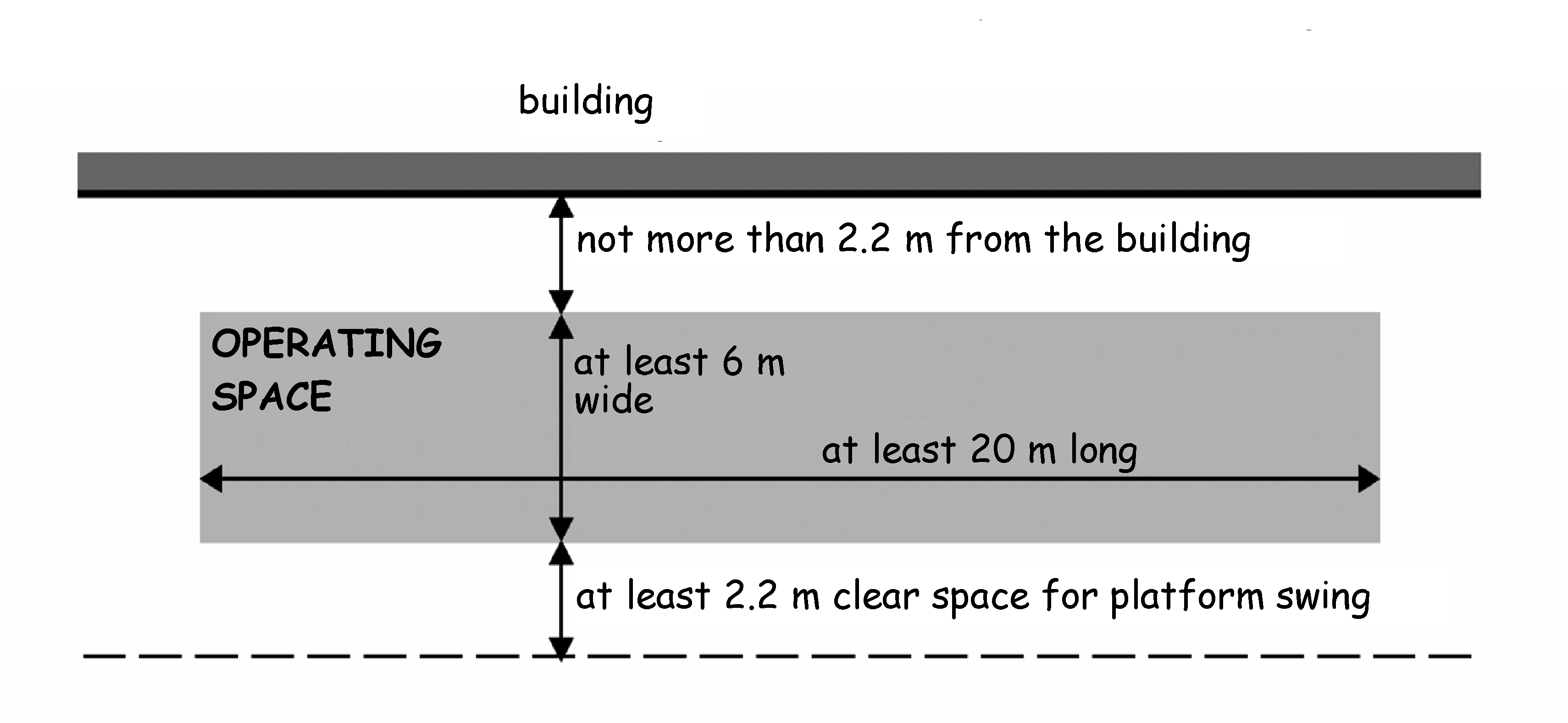
2.12.4 Access for fire and rescue service personnel
It is common practice for fire and rescue service personnel to enter a building through the normal entrances and fight the fire head on. This is termed ‘offensive fire-fighting’.
In order to allow unobstructed access to a building for fire and rescue service personnel, a paved (or equivalent) footpath at least 900mm wide (see also Section 4 Safety) should be provided to the principal entrance, or entrances, of a building. In addition, where vehicle access is not possible to within 18m of the dry riser inlets (see clause 2.12.1) a footpath should also be provided to the riser inlets.
Every elevation which is provided with vehicle or pedestrian access for fire and rescue service personnel, should have a door giving access to the interior of the building. Inward opening doors are preferable because this allows easier forced entry by fire and rescue service personnel should the need arise. However an outward opening final exit door or emergency door (see clause 2.9.16) should also be considered as providing suitable access.
2.13 Fire and rescue service water supply
#Source page 35
Mandatory Standard
| Standard 2.13 Every building must be provided with a water supply for use by the fire and rescue service. |
2.13.0 Introduction
Fire-fighting operations depend on a sufficient supply of water in order to control fire growth and assist in effective rescue operations.
The fire and rescue service should be provided with a water supply to assist with their fire-fighting and rescue operations. This is normally provided from public water mains through fire hydrants or alternative water supplies such as tanks or reservoirs may be provided.
In some cases, the existing water supply may be sufficient and there is no need to provide additional water supplies. Therefore, it is important to consult the fire and rescue service and water authority early in the design process to establish what water supply, if any, should be provided in order to carry out their statutory duties under the Fire (Scotland) Act 2005 as amended.
Conversions - in the case of conversions, as specified in regulation 4, the building as converted shall meet the requirement of this standard (regulation 12, schedule 6).
2.13.1 Water supply
Every non-domestic building should, be provided with a water supply to assist fire fighting and rescue operations from:
•a public water supply, or
•an alternative water supply.
2.13.2 Public water supply
An existing hydrant may be used to supply water for fire-fighting where:
•the building has a footprint of not more than 280m2, and
•the hydrant is located not more than 100m away from the building, and
•no compartment has an area more than 280m2, and
•top storey not more than 7.5m above access level.
Positioning of hydrants - a building with a footprint or compartment area of more than 280m2 should be provided with at least 1 water hydrant. However where no piped water supply is available, an alternative source of supply should be provided (clause 2.13.3).
The water hydrants should be positioned externally, for each building or where common to more than one building:
•not more than 60m from at least one normal entrance to the building, and
•distributed around the building so that every external elevation of the building is within 60m from a hydrant, and
•so that hydrants are at least 6m away from the building, and
•located adjacent to a parking space for a pumping appliance, and
•where a parking space is provided for a fire appliance in accordance with clause 2.14.7 (fire mains), the water hydrant should be located adjacent to that parking space, and
•so as to be accessible for use at all times, and
•so that there is a clear route for the fire hose between the hydrant and the building, and
•the hydrants are constructed in accordance with BS 750: 2006.
A fire hydrant should be clearly indicated by a plate, affixed nearby in a conspicuous position, in accordance with BS 3251:1976.
Performance criteria - a hydrant should be connected to a water service pipe capable of delivering water at a flow rate of at least 1500 litres per minute, provided by a water main vested in a public water authority or a supply provided under the Fire (Scotland) Act 2005 as amended. Alternative arrangements, including private supplies, should be agreed with the verifier and water authority, where relevant.
Whilst it is desirable to achieve 1500 litres per minute flow rate, it is accepted that the flow rates in the water mains may not achieve this. Localised areas throughout Scotland may not be supplied by mains water or, where mains water is available, the pressure and flow rates in the main may not be sufficient for fire-fighting operations. Skilled pump operators can regulate the water supplies to the fire-fighters and take care not to overdraw the mains especially where the mains pressure and flow rates are poor.
Portable pumps - in some cases, where there are insufficient water hydrants distributed around existing buildings, it is normal practice to deploy portable pumps to relay water supplies to where the water is needed. Whilst this method of water distribution is quite common, it should be avoided for new developments because of the time delay in supplying water to the fire-fighters.
2.13.3 Alternative water supply
Where no piped water supply is available, or there is insufficient pressure and flow in the water main, or an alternative arrangement is proposed, the alternative source of supply should be provided in accordance with the following recommendations:
•a charged static water tank of at least 45,000 litres capacity, or
•a spring, river, canal, loch or pond capable of providing or storing at least 45,000 litres of water at all times of the year, to which access, space and a hard standing are available for a pumping appliance (see clause 2.12.2), or
•any other means of providing a water supply for fire-fighting operations considered appropriate by the fire and rescue service.
2.14 Fire and rescue service facilities
#Source page 36
Mandatory Standard
| Standard 2.14 Every building must be designed and constructed in such a way that facilities are provided to assist fire-fighting or rescue operations. |
2.14.0 Introduction
Facilities within a building are provided to assist the fire and rescue service carry out their statutory duties as efficiently and safely as possible. Fire and rescue service personnel are trained to enter buildings following the outbreak of fire to assist with any evacuation of the building occupants, effect rescues of any casualties and to fight fires. Fire-fighters operational duties are made on a statutory basis in the Fire (Scotland) Act 2005 as amended, which states:
“Each relevant authority shall make provision for the purpose of –
1.extinguishing fires in its area
2.protecting life and property in the event of fires in its area.”
The extent of fire development will vary with each incident and in any situation, the fire and rescue service will assess the need to evacuate the entire building whilst the fire is brought under control. Sometimes, the fire can develop to such an extent that additional fire-fighting teams may need to be summoned from other fire stations or fire authorities.
Fire-fighters will normally enter a building through the main entrance and attempt to attack the fire. This is termed ‘offensive fire-fighting’ and is normal practice regardless of whether people are in the building or not. When conditions within the building become too hazardous for fire-fighters to remain, they will normally retreat a safe distance away from the building and implement ‘defensive’ fire-fighting tactics to control the spread of fire. In cases where a large fire develops, numerous fire-fighting teams may be involved using a combination of offensive and defensive tactics until the fire is brought under control and extinguished.
Whilst fire-fighters are professionally trained to deal with all types of fire condition, the fire and rescue service facilities within a building are important to reduce fire attack time which in turn, could save lives, limit the fire damage to property and improve fire-fighter safety.
Due to the special fire precautions within residential care buildings, hospitals and enclosed shopping centres, additional guidance is grouped in the Annexes. The intention is to help designers and verifiers find the information they require quickly when designing or vetting such buildings. However it is important to remember that the guidance in the annexes is in addition and supplementary to the guidance to Standard 2.1 to 2.15. For additional guidance on:
•residential care buildings, see annex 2.A
•hospitals, see annex 2.B, and
•enclosed shopping centres, see annex 2.C.
Conversions - in the case of conversions, as specified in regulation 4, the building as converted shall meet the requirement of this standard (regulation 12, schedule 6).
2.14.1 Fire and rescue service facilities
Fire and rescue service facilities may need to be provided in a building to assist with any evacuation of the building occupants, effect rescues of any casualties and to fight fires. The time taken for fire and rescue service intervention is dependent on a number of variables. The time to contact the emergency services, the location of the building in relation to the fire station and the height of the floor of fire origin above or below the fire and rescue service access level.
Fires in tall buildings or in basement storeys may present additional risks to fire and rescue service personnel. Fire and smoke can suddenly change direction and intensity due to a number of factors which might induce reverse air flows. For example, the wind direction and velocity (which increases with height) could have a significant impact when fire-fighters open the door to the room or storey of fire origin. Similarly, limited ventilation available in a basement storey can lead to heat and smoke build up that is released through the opening the fire-fighters are using as an entry point.
It is important that the facilities to assist the fire and rescue services take account of the building design. The Building Disaster Assessment Group carried out extensive research on behalf of the UK Government to assess the interaction between building design and the operational response of fire and rescue services. The subjects covered by the research included:
•physiological performance criteria for fire-fighting
•fire-fighting in under-ventilated compartments, and
•fire-fighting media in high-rise buildings.
The research is available on the UK Government website http://www.communities.gov.uk/fire/.
2.14.2 Number and type of facilities
The further fire-fighters need to travel to reach the seat of the fire above or below ground, the greater the risk. Therefore, the number and type of facilities provided should be based on the height of the topmost storey above the fire and rescue service access level, the depth of any basement storeys below the access level and the distance from any fire mains outlets (see clause 2.14.7).
The type of facilities that are necessary may include:
•fire-fighting stairs
•fire-fighting lifts
•fire-fighting lobbies, and
•heat and smoke control (e.g. natural or mechanical ventilation).
Height of topmost storey - building design should complement fire-fighting and rescue capability. The 7.5m storey height above the ground is historically linked to the height at which fire and rescue service personnel can rescue occupants using the standard 13.5m portable ladder. Whilst this practice is no longer common, for health and safety reasons, fire-fighters continue to carry out external rescues as a last resort and building design should recognise this.
The 18m storey height above the ground is also historically linked with the reach capability of fire and rescue service equipment such as wheeled escape ladders (now obsolete). The general intent is that buildings with a storey at a height of more than 18m above the access level, cannot be easily reached by fire and rescue service equipment and personnel. Therefore, at least 1 fire-fighting shaft (fire-fighting stair, fire-fighting lobby, fire mains and in some cases a fire-fighting lift) is provided within the building to allow equipment and personnel to be deployed as quickly as possible.
In addition, fire-fighters cannot apply water jets from fire hoses onto external walls high above the ground because of the limited reach capability. The guidance throughout this handbook including Standard 2.7, spread on external walls, recognises this limitation.
The fire and rescue service facilities recommended in the table should be applied on every storey, however the lowest basement storey sets the level of facilities recommended throughout the basement storeys only. The depth of the lowest basement storey is measured from the fire and rescue service access level to the upper surface of the lowest basement storey. The height of the topmost storey of a building is measured from the fire and rescue service access level to the upper surface of the topmost storey.
Table 2.16. Fire and Rescue Service facilities
| Height and depth of storey above or below fire and rescue service access level [1] | Shops, factories, storage buildings and open sided car parks where the area of any storey is more than 900m2 [2] | All other buildings [2] |
|---|---|---|
| Basements at a depth more than 10m below access level | Fire-fighting stair (see clause 2.14.3), fire-fighting lift (see clause 2.14.4), fire-fighting lobby (see clause 2.14.5), ventilation to stair and lobby (see clause 2.14.6), dry fire main (see clause 2.14.7) | |
| Basements at a depth not more than 10m below access level | Fire-fighting stair (see clause 2.14.3), fire-fighting lobby (see clause 2.14.5), ventilation to stair and lobby (see clause 2.14.6), dry fire main (see clause 2.14.7) | Fire-fighting stair (see clause 2.14.3), ventilation to stair (see clause 2.14.6) |
| Topmost storey not more than 7.5m above access level [3] | Fire-fighting stair (see clause 2.14.3), unvented fire-fighting lobby (see clause 2.14.5), ventilation to stair (see clause 2.14.6), dry fire main (see clause 2.14.7) | Fire-fighting stair (see clause 2.14.3), ventilation to stair (see clause 2.14.6) |
| Topmost storey more than 7.5m but not more than 18m above access level | Fire-fighting stair (see clause 2.14.3), fire-fighting lobby (see clause 2.14.5), ventilation to stair and lobby (see clause 2.14.6), dry fire main (see clause 2.14.7) | Fire-fighting stair (see clause 2.14.3), unvented fire-fighting lobby (see clause 2.14.5), ventilation to stair (see clause 2.14.6), dry fire main (see clause 2.14.7) |
| Topmost storey more than 18m but not more than 50m above access level | Fire-fighting stair (see clause 2.14.3), fire-fighting lift (see clause 2.14.4), fire-fighting lobby (see clause 2.14.5), ventilation to stair and lobby (see clause 2.14.6), dry fire main (see clause 2.14.7) | |
| Topmost storey more than 50m but not more than 60m above access level | Fire-fighting stair (see clause 2.14.3), fire-fighting lift (see clause 2.14.4), fire-fighting lobby (see clause 2.14.5), ventilation to stair and lobby (see clause 2.14.6), wet fire main (see clause 2.14.7) |
Additional information:
1.The access level is the level at which the fire and rescue service enter the building to commence fire-fighting and rescue operations.
2.Ventilation to stairs includes both escape stairs and fire-fighting stairs (see clause 2.14.6).
3.For open side car parks there is no need for fire-fighting lobbies or dry fire mains.
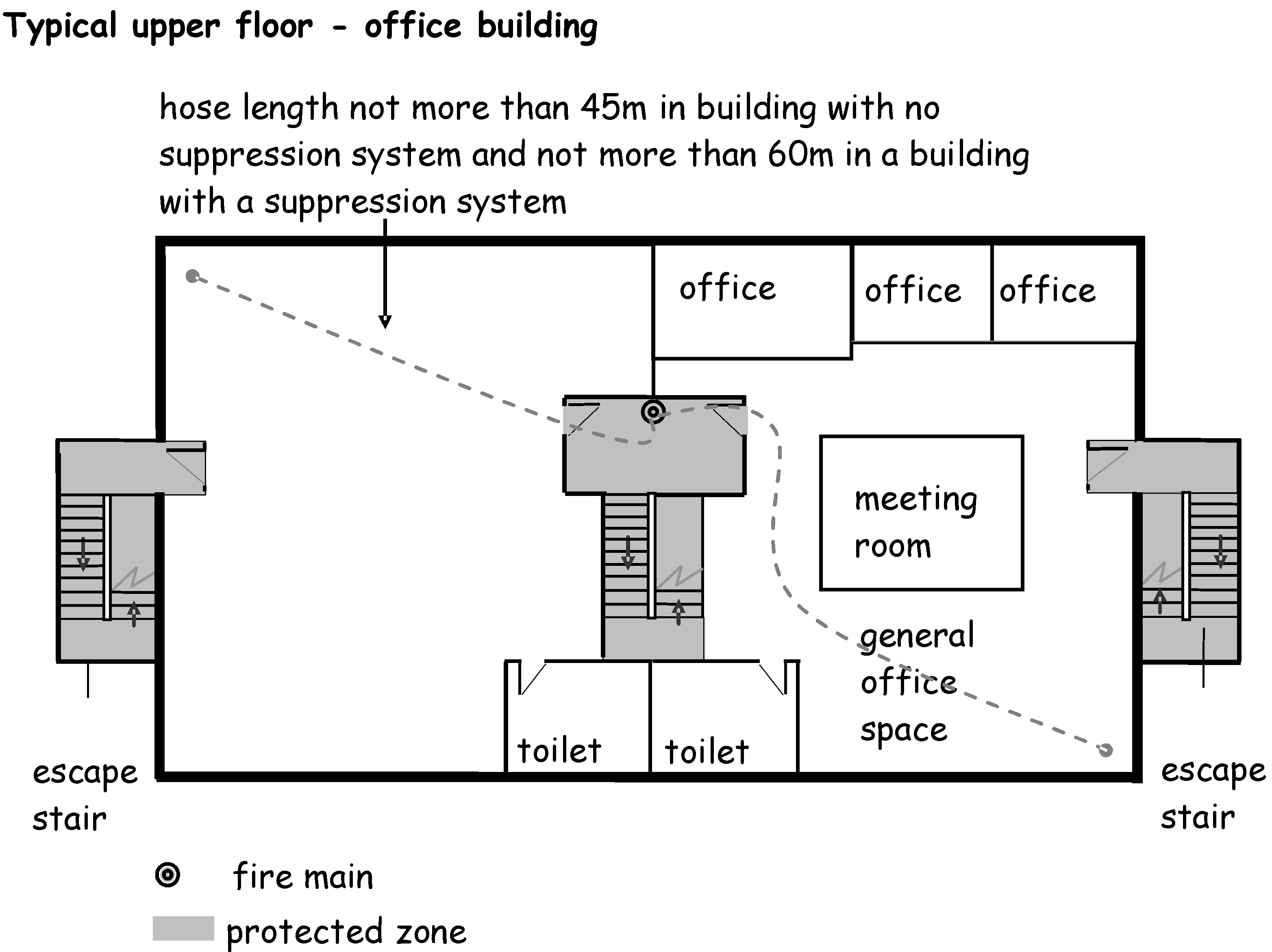
2.14.3 Fire-fighting stairs
At least 1 fire-fighting stair should be provided to assist fire-fighters to access the fire and if necessary escape from the fire in relative safety. The fire-fighting stair should be at least 1.0m wide measured between handrails to provide fire and rescue service personnel sufficient room to carry fire-fighting and rescue equipment.
A fire-fighting stair should be contained within a protected zone. The enclosing structure of the protected zone should have at least a medium fire resistance duration and should have a long fire resistance duration where it serves:
•a basement storey at a depth of more than 10m below the fire and rescue service access level
•a shop, factory, storage building or an open sided car park where the area of any storey is more than 900m2, or
•any building where the topmost storey is more than 18m above the fire and rescue service access level.
However where the elements of structure in a building have a medium fire resistance duration, the protected zone need only have a medium fire resistance duration.
A self-closing fire door in the enclosing structure of a protected zone should have at least a medium fire resistance duration. In some cases an escape stair can be used as a fire-fighting stair. For example, in single stair buildings.
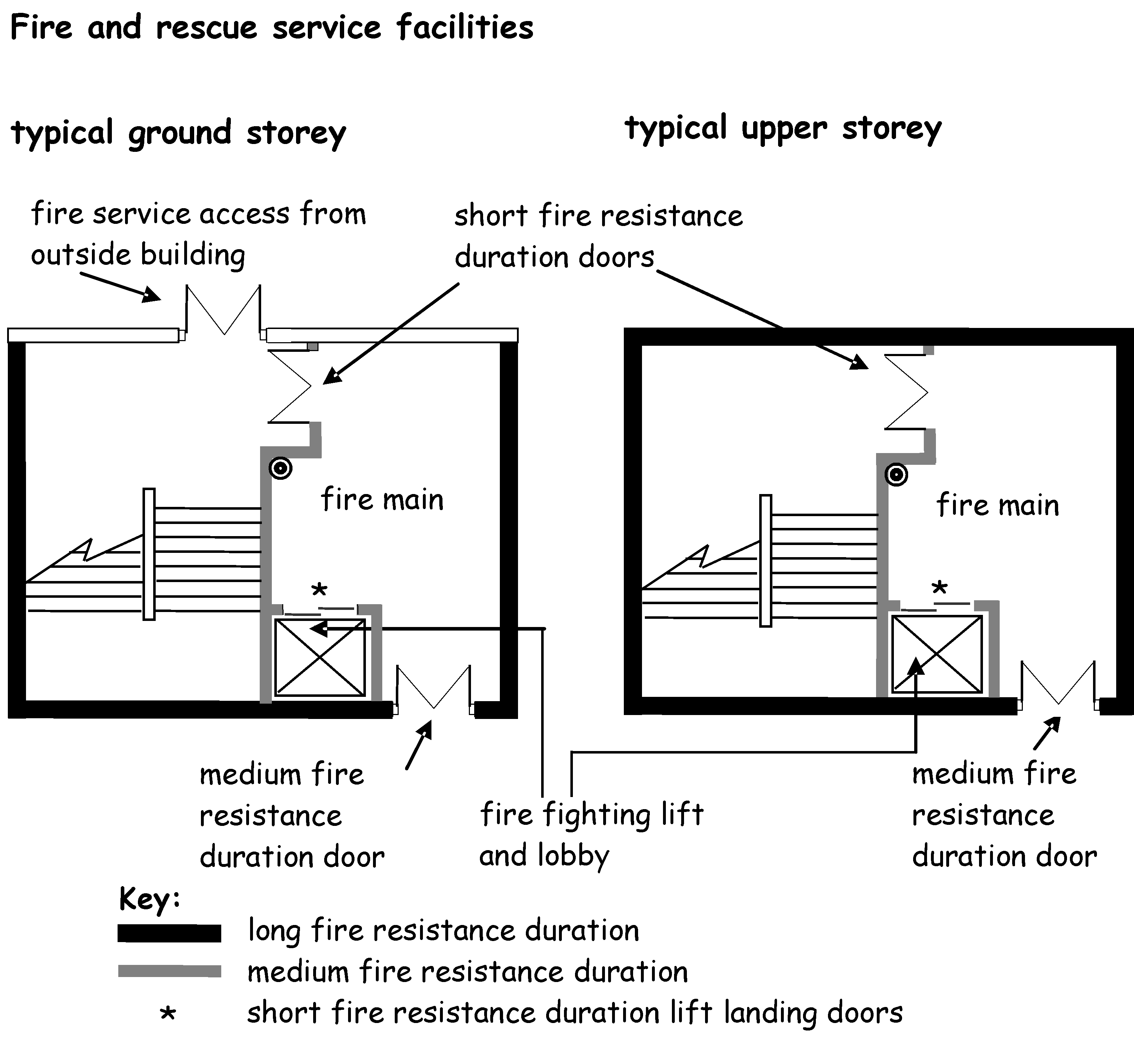
2.14.4 Fire-fighting lifts
A fire-fighting lift allows fire and rescue service personnel to transport equipment to a floor of their choice as quickly as possible. The lift also allows fire-fighters to access several floors quickly to assess the situation and to rescue any casualties.
The lift installation includes the lift car itself, the lift well and the lift machinery space, together with the lift control system and the lift communication system. The lift control and communication system should be capable of being used under the direct control of the fire and rescue services. The lift installation should conform to BS EN 81: Part 72: 2003 and BS EN 81: Part 1: 1998 or BS EN 81: Part 2: 1998 depending on the type of lift.
A fire-fighting lift should be located within a protected zone and constructed within its own compartment having at least a medium fire resistance duration. The lift landing doors need only achieve a short fire resistance duration.
The lift should only be entered from:
•a fire-fighting lobby with not more than 1 door to the room or storey it serves, or
•an access deck.
A fire-fighting lift need not serve the top storey of a building where:
•the top storey is for service plant use only, and
•access to the plant room is from the fire-fighting stair from the storey below, and
•the foot of the fire-fighting stair is not more than 4.5m from the fire-fighting lift.
2.14.5 Fire-fighting lobbies
A fire-fighting lobby serves a fire-fighting stair and a fire-fighting lift where appropriate (see table to clause 2.14.2). Where a fire-fighting lobby is required (see table to clause 2.14.2), it should be located within a protected zone and should be provided on every storey. The purpose of a fire-fighting lobby is:
•to allow fire-fighters to set up a forward control point at least 1 floor below the fire floor where fire-fighters and fire-fighting equipment can safely be assembled before commitment to fire-fighting and rescue operations
•to protect fire-fighters when making their final approach to the fire floor
•to protect any evacuees or fire-fighters who might be using the stair from a fire in the lift well or lift machine room
•to provide fire-fighters with a safe route of egress from the fire, or if the lift should fail or its reliability becomes uncertain
•to protect fire-fighters who might accidentally arrive at the fire floor
•to reduce the potential for fire-fighters to become disoriented due to poor visibility, and
•to protect the lift from the effects of fire and smoke in adjoining accommodation.
Therefore, a fire fighting lobby should be provided on every storey, and include within it, an area of at least 5m2 with all principal dimensions at least 1.5m. This allows fire-fighters sufficient room to lay out hose and connect to the outlet from a fire main.
In order to protect fire-fighters, only 1 door should be provided between the fire-fighting lobby and the remainder of the building in the following high risk cases:
•a basement storey at a depth of more than 10m below the fire and rescue service access level
•a shop, factory, storage building or an open sided car park where the area of any storey is more than 900m2, or
•any building where the topmost storey is more than 18m above the fire and rescue service access level.
2.14.6 Heat and smoke control
The fire and rescue service should be provided with the facility to release smoke and heat from a fire during their fire-fighting and rescue operations. Ventilation should be provided to every escape stair, fire-fighting stair and fire-fighting lobby unless excluded by the table to clause 2.14.2. The efficiency of the ventilators depends upon the prevailing wind and it is important that fire-fighters can control the opening and closing of the ventilators on arrival at the building.
Ventilators should be fitted with a simple handle or lock that can be operated by fire-fighters. If ventilators are not easily accessible they should be operated by a mechanism positioned within the building at the fire and rescue service access point. In the case of an escape stair and fire-fighting stair, a local control should also be provided at the topmost storey. This will allow fire-fighters flexibility in their operations.
Escape stairs and fire-fighting stairs - ventilation should be provided to every escape stair and every fire-fighting stair by:
•a ventilator of at least 1m2 at the top of the stair, or
•an ventilator of at least 0.5m2 at each storey on an external wall, or
•‘Smoke shafts protecting fire-fighting shafts; their performance and design’ (BRE, 2002).
Fire-fighting lobbies - ventilation should also be provided in every fire-fighting lobby unless excluded by the table to clause 2.14.2, by:
•a ventilator of at least 1m2 at each storey on an external wall, or
•‘Smoke shafts protecting fire-fighting shafts: their performance and design’ (BRE, 2002).
A natural or mechanical smoke ventilation system used to satisfy Standard 2.9 may also be used to satisfy Standard 2.14 with the agreement of the fire and rescue service.
2.14.7 Fire mains
Where there is an outbreak of fire high above the fire and rescue service access level, the time taken to set up a forward control point, assess the situation and carry hoses up several flights of stairs can be considerable. Therefore, in a building where the topmost storey is more than 7.5m, a fire main should be installed in the fire-fighting lobby to help reduce fire attack time. Fire mains are also necessary to help fire-fighters to attack large fires in basement storeys (see table to clause 2.14.2).
In some cases, (see table to clause 2.14.2) fire mains may be located in an unventilated fire-fighting lobby (e.g. protected lobby).
A dry fire main is a pipe installed in a building for fire-fighting purposes, which is normally dry but is capable of being charged with water by pumping from a fire and rescue service appliance. A dry fire main is commonly referred to as a ‘dry riser’.
Dry fire mains should be designed and constructed in accordance with BS 9990: 2006.
The inlets to the risers should be located externally to the building and not more than 18m from a parking space suitable for a pumping appliance. There should be a clear hose route between the appliance and the inlet.
Wet fire mains - the pressure and flow rates delivered from fire mains reduce with height above the ground and may not provide an effective water jet from fire-fighting hoses. Therefore, where the height of the topmost storey is more than 50m above the fire and rescue service access level, wet rising mains should be installed. A wet fire main is a pipe which is constantly charged with water supplied from a suction tank and pump. The suction tank should have an inlet for the emergency replenishment of water and is clearly visible to the fire and rescue services. A wet fire main is commonly referred to as a ‘wet riser’.
Fire mains outlets should be provided on every storey of a building and the basement storey to permit fire-fighting operations to be conducted at any floor level when it is safe for fire and rescue service personnel to do so.
If an automatic fire suppression system is installed in the building, no point on the storey should be more than 60m from the fire main outlet, measured along an unobstructed route for laying a fire hose. If the building is not fitted with an automatic fire suppression system, no point on the storey should be more than 45m from the outlet.
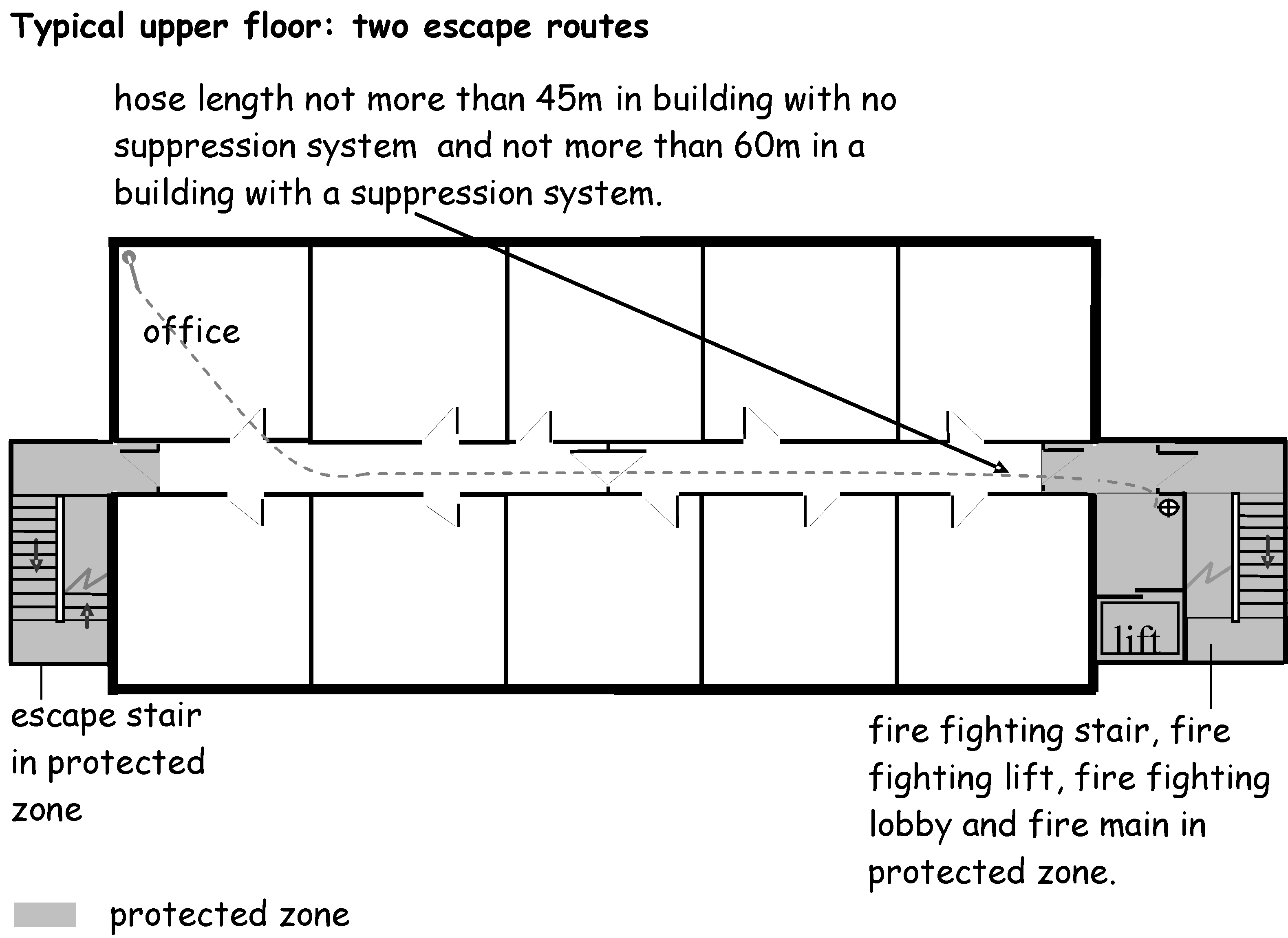
2.14.8 Fire shutters
All fire shutters in compartment walls (see clause 2.1.14) should be capable of being opened and closed manually by fire and rescue service personnel.
2.14.9 Venting of heat and smoke from basements
The build up of smoke and heat in basement storeys can seriously inhibit the ability of the fire and rescue service to carry out fire-fighting and rescue operations. The products of combustion from basement fires tend to escape via stairways, making access difficult for fire-fighters. Ventilation can reduce temperatures and improve visibility. Therefore smoke outlets, communicating directly with the external air, should be provided from every basement storey, and where the basement storey is divided into compartments, from every compartment. However smoke outlets need not be provided:
•in open sided car parks, or
•where the floor area of the basement storey is not more than 200m2, or
•where the basement storey is at a depth of not more than 4.5m, or
•where there is a window or windows opening direct to the external air having a total area not less than 1% of the floor area, or
•where the basement storey or part of the basement storey is used as a strong room, or
•where the basement storey has an automatic fire suppression system and is ventilated by a mechanical smoke and heat extraction system incorporating a powered smoke and heat exhaust ventilator which has a capacity of at least 10 air changes per hour and conforms to BS 7346: Part 2: 1990 with a class D level of performance or BS EN 12101: Part 3: 2002 Class F300.
Smoke outlets should:
•have an area of at least 2.5% of the floor area of the compartment they serve, and
•sited at high level, either in the ceiling or in the wall of the space they serve, and
•evenly distributed around the perimeter of the building, and
•discharge directly to the open air at a point at least 2m, measured horizontally, from any part of an escape route or exit, and
•where they serve a place of special fire risk, they are separate from smoke outlets from other areas, and
•where the outlet is a smoke shaft, the enclosing structure should have at least a medium fire resistance duration, other than the smoke inlets and outlets to the shaft.
If an outlet terminates in a readily accessible position, it may be covered by a panel or pavement light that is capable of being opened by fire and rescue service personnel. Covered outlets should have a sign stating ‘Smoke outlet from basement’ fixed adjacent to each external outlet point.
If a smoke outlet is inaccessible to the fire and rescue services, it should be unobstructed but may be covered by a non-combustible grille or louvre.
2.15 Automatic fire suppression systems
#Source page 37
Mandatory Standard
| Standard 2.15 Every building must be designed and constructed in such a way that, in the event of an outbreak of fire within the building, fire growth will be inhibited by the operation of an automatic fire suppression system. Limitation: This standard applies only to a building which: |
2.15.0 Introduction
Automatic fire suppression systems help control the intensity and size of a fire, suppress it and in some cases may even extinguish it. It can provide occupants, including vulnerable occupants, with the additional time necessary to escape following the outbreak of fire. The primary role of the suppression system may be for life safety or property protection.
Life safety - automatic fire suppression systems react to heat therefore, the greatest protection is afforded to those occupants outwith the room of fire origin. Automatic suppression may provide some benefit to occupants in the room of fire origin where for example the fire growth is fast and the temperatures allow the sprinkler system to open early in the development phase of the fire. The spray pattern delivered from the heads should control fire spread, reduce temperatures and dilute the smoke. In some cases, the fire might be extinguished if the fire is not shielded from the sprinkler spray. A smaller fire means that the fire and rescue service will be able to bring the fire under control and extinguish it much more quickly.
Property protection - concerns about fire have traditionally centred on life protection rather than asset protection. A primary objective of the building standards system however is to ‘further the achievement of sustainable development’. The sustainability of communities could be served by the protection against both deliberate and accidental fires in buildings such as schools that serve as social assets and components of the local economic network. There is on average 152 fires in Scottish schools each year that result in significant costs in terms of the damage and disruption they cause.
For the purposes of this standard a school is a building in which primary and or secondary education is given.
Annexes - due to the special fire precautions within residential care buildings, hospitals, and enclosed shopping centres, additional guidance is grouped in the annexes. However it is important to remember that the guidance in the annexes is in addition and supplementary to the guidance to Standard 2.1 to 2.15. For additional guidance on:
•residential care buildings, see annex 2.A
•hospitals, see annex 2.B
•enclosed shopping centres, see annex 2.C.
Conversions - in the case of conversions, as specified in regulation 4, the building as converted shall meet the requirement of this standard (regulation 12, schedule 6).
2.15.1 Automatic fire suppression systems
The term automatic fire suppression system includes sprinkler systems but provides the opportunity for designers to propose other systems which may be just as effective. The key characteristics of the system are:
•it should be automatic and not require people to initiate its activation
•it should be a fire suppression system, one designed specifically to deal with fires rather than other hazards.
Life safety systems - where a system is installed for life safety purposes (other than in residential care buildings) as well as property protection, the additional recommendations for a life safety system are contained in the LPC Rules for Automatic Sprinkler Installations 2009 incorporating BS EN 12845: 2004. The suppression system should cover the entire building including roof voids where necessary.
Compensatory feature - automatic fire suppression may also be chosen by the designer as part of the escape strategy or as a compensatory feature where the recommendations in this handbook have been varied in some way. Where a system is installed as a compensatory feature the additional recommendations for a life safety system contained in the LPC Rules for Automatic Sprinkler Installations should be applied.
Alternative suppression systems - there are many alternative or innovative fire suppression systems available, including systems utilising gaseous, mist or fog systems. Verifiers should satisfy themselves that such systems have been designed and tested for use in non-domestic buildings and are fit for their intended purpose (see Section 0).
2.15.2 Residential care buildings
A residential care building should have an automatic life safety fire suppression system designed and installed in accordance BS 9251: 2005.
2.15.3 Hospitals
Due to the unique operational requirements of hospitals certain departments and high risk areas should have an automatic life safety fire suppression system designed and installed in accordance with guidance set out in clause 2.1.2.
2.15.4 Enclosed shopping centres
An enclosed shopping centre should have an automatic life safety fire suppression system designed and installed in accordance with guidance set out in annex 2.C.
2.15.5 Schools
A school building should have an automatic fire suppression system installed for asset protection to further the achievement of sustainable development.
A fire risk assessment should be carried out to identify all the fire hazards that may be present. This will determine the appropriate hazard classification and form the basis of the automatic fire suppression system design. The hazard classification dictates the performance criteria for the suppression system, the water supply arrangements, components, design of pipework and cost.
The hazard classification for schools is normally Ordinary Hazard Group 1 (OH1). In some cases Light Hazard (LH) classification may be used where the building or compartment is not more than 126m2. See BS EN 12845: 2004 for more detailed information. It is important to recognise that clients or insurers may specify a different hazard classification, depending on the outcome of the fire risk assessment.
BS EN 12845: 2004 gives guidance on special hazards such as:
•aerosol storage
•flammable liquids storage
•polypropylene or polyethylene storage bins
•computer areas
•theatres
•drying ovens
•areas where corrosive atmospheres may exist.
Design criteria - to ensure the suppression system is robust, the automatic fire suppression system should be designed, installed and maintained in accordance with the LPC Rules for Automatic Sprinkler Installation. These rules contain the text of BS EN 12845: 2004 together with a series of Technical Bulletins which complement the recommendations (e.g. Technical Bulletin 221, Sprinkler protection of schools). The suppression system should cover the entire building including roof voids where necessary.
Guidance on the key issues to be considered in sprinkler system design can also be found in the BAFSA ‘Code of Practice on Sprinklers in Schools’.
Existing schools - where additional accommodation is provided to an existing school by either extending the school or constructing another school building on the existing school grounds, the automatic fire suppression system should be extended into the extension or new building.
Where an existing school does not have an automatic fire suppression system, a system should still be considered for the additional accommodation.
There may be smaller school buildings on existing school grounds where it is not reasonably practicable to install an automatic fire suppression system. This would be where the benefits of a system are clearly outweighed by the costs. However, the designer should check whether an automatic fire suppression system is required to satisfy any school client or insurer requirements.
In determining whether it is not reasonably practicable to install an automatic fire suppression system all relevant factors should be taken into account. The primary consideration is likely to be the building size and proportionate cost of the fire suppression system in relation to the overall project cost. The expected life of the building is also an important factor as some buildings may only be needed for a short time. For example temporary classrooms needed for school refurbishments or other construction.
Secondary considerations include the risk of deliberate or wilful fire-raising in the immediate geographic area, for which advice could be sought from the local fire and rescue service. There is also the potential impact of any damage or disruption caused by fire.
Where an existing school is being altered, there is no need to install an automatic fire suppression system. In the case of an existing school building which has an automatic fire suppression system installed, it is important that the system’s operation is not compromised by any building work.
2.15.6 Compartmentation
There is recognition within the guidance given under Standard 2.1 that automatic fire suppression can have a role to play in limiting potential fire growth. It is possible therefore to increase the compartmentation area/size in certain building types. These building types are identified in the tables to clause 2.1.1; the intention is to allow design flexibility.
2.15.7 Phased evacuation
Tall buildings take longer to evacuate and where the building is at a height of more than 25m it is beyond the reach capability at which the Fire and Rescue Service can effect external rescue. Therefore, when phased evacuation is adopted in buildings, additional active and passive fire protection measures will be necessary. As part of the package of fire safety measures an automatic life safety fire suppression system should be provided on every storey.
Fire suppression should be appropriate to the occupancy and should be determined on the basis of a risk assessment. Where provided, an automatic life safety sprinkler system should be designed and installed in accordance with the LPC Rules for Automatic Sprinkler Installations 2009, Incorporating BS EN 12845: 2004 including life safety recommendations.
2.15.8 Water supply
For a suppression system to be effective it is essential that there is an appropriate water supply. Therefore, designers need to discuss with Scottish Water what supply is likely to be available and what pressure can be expected. It is recognised that pressures may vary throughout the day and night, over the year and perhaps in future years. Therefore it is imperative that the system is designed on the basis of what the minimum pressure and flow is likely to be. If there is any doubt, a tank and pump arrangement should be used.
Annex 2.A Additional guidance for residential care buildings
#Source page 38
2.A.0 Introduction
The recommendations contained in this annex are in addition to the guidance to Standards 2.1 to 2.15 and are unique to residential care buildings.
A residential care building is a building used, or to be used, for the provision of:
a.a care home service, or
b.a school accommodation service
and for these purposes, the expressions mentioned in sub-paragraphs (a) and (b) above, have the same meaning as in the Regulation of Care (Scotland) Act 2001.
All residential buildings pose special problems because the occupants may be asleep when a fire starts. In residential care buildings the problems are greater as the mobility, awareness and understanding of the occupants may also be impaired.
The intention of sub-compartmentation and the enclosure of fire hazard rooms is to provide physical barriers to a fire. Automatic fire suppression is intended to limit the development of a fire to the room or space of fire origin and automatic detection provides the early warning of the outbreak of fire. The combination of active and passive fire protection should afford staff and occupants the additional time necessary to evacuate the building safely.
Additional recommendations are provided for compartmentation, cavities, escape, escape lighting, communication and automatic fire suppression.
Residential care buildings are quite diverse and can be used by a variety of occupants, each requiring different types of care to suit their specific needs. Whilst the guidance in this annex is suitable for most residential care buildings, it is accepted that a degree of flexibility should be applied when designing for specialised conditions such as children’s homes or care homes where the occupants suffer from dementia. Any departure from this guidance should be carried out on a risk-based approach and early consultation with the verifier and fire and rescue service is essential.
Fire safety in residential care buildings is also dependent upon the way a building is furnished, staffed and managed. Designers of residential care buildings may need to make reference to the relevant documents which comprise ‘NHS Scotland Firecode’.
2.A.1 Compartmentation
Maximum compartment size - every compartment in a residential care building should be limited to a maximum area of 1500m2. In addition, every upper storey and every basement storey should form a separate compartment.
Sub-compartmentation and the enclosure of fire hazard rooms is to provide physical barriers to a fire, thus affording the staff and occupants additional time to evacuate the building safely. Every compartment in a residential care building should be divided into at least two sub-compartments by a sub-compartment wall with a short fire resistance duration, so that each sub-compartment is not greater than 750m2.
Fire hazard rooms
In order to contain a fire in its early stages, the following rooms are considered to be hazardous and should be enclosed by walls with a short fire resistance duration:
•chemical stores
•cleaners' rooms
•clothes storage
•day rooms with a floor area greater than 20m2
•smoking rooms
•disposal rooms
•lift motor rooms
•linen stores
•bedrooms
•kitchens
•laundry rooms
•staff changing and locker rooms, and
•store rooms.
Corridor escape routes
Where any corridor escape route serves sleeping accommodation it should be constructed of walls providing short fire resistance duration and any door in the wall should be a suitable self-closing fire door with a short fire resistance duration. However the fire door to the cleaners cupboard need not be self closing provided it is lockable.
Combustibility
A sub-compartment wall can be constructed with combustible material (i.e. material that is low, medium, high or very high risk) provided the wall has short fire resistance duration.
Junctions with external walls
Where a lower roof abuts an external wall, the roof should provide a medium fire resistance duration for a distance of at least 3m from the wall.
2.A.2 Cavities
Where cavity barriers are installed between a roof and a ceiling above an undivided space, cavity barriers should be installed not more than 20m apart (see clause 2.4.3).
2.A.3 Escape
Number of exits - at least 2 exits should be provided from any storey in a residential care building. However additional exits may be needed in accordance with clause 2.9.7. Each sub-compartment should be provided with at least 2 exits by way of protected zones and/or unprotected zones to adjoining, but separate, compartments or sub-compartments.
Locks
Residential care buildings can present difficulties when assessing the risks associated with security against the need to evacuate the building safely in the case of fire. Some residential care buildings are a home to people who might put themselves at risk. An example would be a 2 storey residential home for the elderly, mentally infirm, where there is concern about residents falling down stairs. In such cases, variation in the guidance to Standard 2.9 would be entirely appropriate where the risk of death or injury from falls is assessed against the hazards associated with fire. The security measures proposed should therefore take account of these hazards and extra emphasis may need to be placed on management control and/or any automated life safety systems to ensure the safe evacuation of the building.
Travel Distance
Travel distance may be measured to a protected door in a sub-compartment. The maximum travel distance from any point within a compartment should be not more than 64m to:
•each of 2 adjoining compartments, or
•an adjoining compartment and an escape stair or a final exit, or
•an adjoining compartment and a final exit, or
•an escape stair and a final exit.
Horizontal Evacuation - in residential care buildings, occupants may need to be evacuated horizontally through a protected door into an adjoining compartment. In such cases, each compartment should be capable of holding the occupancy capacity of that compartment and the occupancy capacity of the largest adjoining compartment.
Where the travel distance is measured to a protected door in a compartment wall or sub-compartment wall in a residential care building, the escape route should not pass through any of the fire hazard rooms listed in clause 2.A.1.
Occupancy of bedrooms
No room intended for sleeping should be used by more than 4 people.
2.A.4 Escape lighting
Emergency lighting should be installed in:
•a room with an occupancy capacity of more than 10 and any protected zone or unprotected zone serving such a room
•a protected zone or unprotected zone serving a storey which has 2 exits, other than a storey in a building not more than 2 storeys high with a combined floor area of not more than 300m2 and an occupancy capacity of not more than 10, and
•a protected zone or unprotected zone in a single stair building of 2 storeys or more and an occupancy capacity of 10 or more.
2.A.5 Communication
An automatic fire detection and alarm system should be installed in every residential care building to ensure that staff and residents are given the earliest possible warning of the outbreak of fire anywhere in the building. This early warning should allow the staff and residents sufficient time to evacuate the building, if necessary.
The automatic fire detection and alarm system should be designed and installed in accordance with the guidance in BS 5839: Part 1: 2002 Category L1 and in accordance with the recommendations below:
a.detection need not be provided in the following locations:
b.manual fire alarm call points manufactured to BS EN 54: Part 11: 2001 (Type A) should be located and installed in accordance with BS 5839: Part 1: 2002
c.the fire alarm should be activated on the operation of manual call points, automatic detection or the operation of the automatic life safety fire suppression system
d.the building should be divided into detection zones not extending beyond a single compartment
e.the audibility level of the fire alarm sounders should be as specified in BS 5839: Part 1: 2002 except in a place of lawful detention including prisons, the alarm need not be sounded throughout the entire building
f.a fire alarm control panel should be provided at the main entrance, or a suitably located entrance to the building agreed with the fire authority
g.on the actuation of the fire alarm, a signal should be transmitted automatically to the fire service, either directly or by way of a remote centre, designed and operated in accordance with BS 5979: 2000.
In the case of a residential care building designed to accommodate not more than 10 residents, the fire detection and alarm system may be installed in accordance with clause 2.11.7 for other residential buildings.
Annex 2.B Additional guidance for hospitals
#Source page 39
2.B.0 Introduction
The recommendations contained in this annex are in addition to the guidance contained in Standards 2.1 to 2.15 and are unique to hospitals.
A hospital is a building used for the treatment of persons suffering from an illness or mental or physical disability or handicap. Whilst all residential buildings pose special problems because the occupants may be asleep when a fire starts, in hospitals the problems are greater as the mobility, awareness and understanding of the occupants may also be impaired. It may not be safe to evacuate them to the outside and in some cases it may even be harmful to move them within the building.
Horizontal evacuation - the staffing levels in hospitals tend to be higher than residential care buildings therefore the fire safety strategy is normally based on the progressive horizontal evacuation of the patients. The object is to move the patients into adjoining compartments or sub-compartments within a short distance where further evacuation can be made if necessary depending on the severity of the risk.
Fire safety in hospitals is also dependent upon the way a building is furnished, staffed and managed. Designers of hospitals may need to make reference to the relevant documents which comprise ‘NHS Scotland Firecode’.
2.B.1 Compartmentation
Compartment
Every compartment in a hospital should be limited to a maximum area of 1500m2. In addition, every upper storey and every basement storey should form a separate compartment.
To assist in the safe horizontal evacuation of the occupants in a hospital, every compartment should be divided into at least 2 sub-compartments by a sub-compartment wall with short fire resistance duration, so that no sub-compartment is more than 750m2. By providing a series of barriers, it is intended that patients or residents will be able to remain in the building and avoid the need for complete evacuation.
Minimum storey areas
Every storey at a height of more than 7.5m containing departments to which patients have access, should either:
•comprise at least 4 compartments, each of which should have an area of at least 500m2, or
•have a hospital street (see clause 2.B.3) and at least 3 other compartments.
In a hospital, every storey at a height of more than 18m containing departments to which patients have access, should either:
•comprise at least 4 compartments, each of which should have an area of at least 500m2, or
•have a hospital street (see 2.B.3) and at least 3 other compartments each of which should have an area of at least 500m2.
Fire hazard departments
A compartment wall with a medium fire resistance duration should be provided between:
•different hospital departments, and
•between a hospital department and a protected zone.
However short fire resistance duration is sufficient in a single-storey hospital.
The departments in list A below should:
•never be directly below, nor directly adjoin, the operating theatres, intensive therapy units or special care baby units, and
•be provided with a fire suppression system (as in clause 2.1.2) where they are directly below, or directly adjoin, any other hospital department to which patients have access.
LIST A
a.boiler house
b.central stores
c.commercial enterprises
d.flammable stores
e.laundry
f.main electrical switchgear
g.main kitchens
h.refuse collection and incineration
i.works department.
A hospital department in list B below should be provided with an automatic fire suppression system (as in clause 2.1.2) where they are directly below, or directly adjoin, operating theatres, intensive therapy units, or special care baby units.
LIST B
a.central staff change
b.central sterile supplies
c.hospital sterilising and disinfecting unit
d.health records
e.pathology
f.manufacturing pharmacy.
Intensive therapy units
Every intensive therapy unit should be divided into at least 2 sub-compartments by sub-compartment wall with short fire resistance duration.
Every entrance to an intensive therapy unit should be either:
a.from a hospital street (see clause 2.B.3), or
b.through a lobby, enclosed with the same fire resistance duration as that recommended for a sub-compartment.
Fire hazard rooms
In order to contain a fire in its early stages, the following rooms are considered to be hazardous and should be enclosed by walls providing a short fire resistance duration (see annex 2.D).
a.chemical stores
b.cleaners’ rooms
c.clothes storage
d.day rooms with a floor area greater than 20m2
e.smoking rooms
f.disposal rooms
g.laboratories
h.lift motor rooms
i.linen stores
j.bedrooms where they are used by:
k.kitchens (other than separate hospital departments)
l.laundry rooms
m.staff changing and locker rooms
n.store rooms
o.X-ray film and record stores
p.all rooms within a main laundry in which delivery, sorting, processing packing and storing are carried out.
Combustibility
Compartment walls or compartment floors in a hospital should be constructed of non-combustible material. However a sub-compartment wall can be constructed with combustible material (i.e. material that is low, medium, high or very high risk) provided the wall has short fire resistance duration.
Junction with external walls
Where a compartment wall or sub-compartment wall meets an external wall, there should be a 1m wide strip of the external wall which has the same level of fire resistance duration as the compartment wall or sub-compartment wall, to prevent lateral fire spread.
Where a lower roof abuts an external wall, the roof should provide a medium fire resistance duration for a distance of at least 3m from the wall.
2.B.2 Cavities
Cavity barriers need not be provided to divide a cavity above an operating theatre and its ancillary rooms.
Where cavity barriers are installed between a roof and a ceiling above an undivided space, the maximum limit of 20m should be applied (see clause 2.4.3).
2.B.3 Escape
The number of exits in a hospital should be calculated in accordance with clause 2.9.1 subject to the additional criteria below.
A minimum of 2 storey exits should be provided from a hospital. The number of storey exits increases in proportion to the number of patient beds. For example:
•any storey with more than 100 patient beds should have at least 3 storey exits
•any storey with more than 200 patient beds should have at least 4 storey exits
•any storey with more than 300 patient beds should have at least 5 storey exits.
Compartment exits - in a hospital where a storey is divided into 3 or more compartments, each compartment should have exits to:
•a compartment and a hospital street, or
•a compartment and an escape stair, or
•a compartment and a final exit.
Each sub-compartment should be provided with at least 2 exits by way of protected zones and unprotected zones to adjoining, but separate, compartments or sub-compartments.
Travel distance in a hospital should not exceed 15m in one direction of travel and 32m in more than one direction. Travel distance may be measured to a protected door in a compartment wall or a sub-compartment wall however the escape route should not pass through any of the fire hazard rooms listed in annex 2.B.1.
In addition, the maximum travel distance from any point within a compartment should be not more than 64m to:
•each of 2 adjoining compartment, or
•an adjoining compartment and an escape stair or a final exit, or
•an adjoining compartment and a final exit, or
•an escape stair and a final exit.
Occupants may need to be evacuated horizontally through a protected door into an adjoining compartment. In such cases, each compartment should be capable of holding the occupancy capacity of that compartment and the occupancy capacity of the largest adjoining compartment.
Hospital streets
A hospital street is a protected zone in a hospital provided to assist in facilitating circulation and horizontal evacuation, and to provide a fire-fighting bridgehead. A hospital street should have an unobstructed width of at least 3m. It should be divided into at least 3 sub-compartments and not contain a shop or other commercial enterprise.
At ground storey level, a hospital street should have at least 2 final exits. At upper storey level there should be access to at least 2 escape stairs accessed from separate sub-compartments, located such that:
•the distance between escape stairs is not more than 64m, and
•the distance of single direction of travel within the hospital street is not more than 15m, and
•the distance from a compartment exit to an escape stair is not more than 32m.
A door from a hospital street to an adjoining compartment should:
•be located so that an alternative independent means of escape from each compartment is available, and
•not be located in the same sub-compartment as a door to a protected zone containing a stairway or lift.
Every escape stair opening into the hospital street should be located so that the travel distance from an escape stair exit to a door leading directly to a place of safety is not more than 64m.
Destination of escape routes
An escape route from a hospital department to which patients have access should be to:
•a place of safety, or
•a protected zone, or
•an unprotected zone in another compartment or sub-compartment.
Bed-patients may be moved to another ward in a different compartment or sub-compartment.
Escape route width
The unobstructed width of every escape route intended for bed-patient evacuation should be at least 1500mm. Doors should be designed to accommodate bed-patient evacuation.
Mattress evacuation stair
In patient sleeping accommodation, an escape stair width should be not less than 1300mm and designed so as to facilitate mattress evacuation. The landing configuration should also follow the guidance in the table below in order to assist the evacuation of bed patients. The additional 200mm for the landing width allows for the return of the balustrade between stair flights. In a straight through stair, the landing width need only be the same as the effective width of the stair.
Table 2.17. Stair and landing configuration for mattress evacuation in mm
| Stair width | Minimum landing width | Minimum landing depth |
|---|---|---|
| 1300 | 2800 | 1850 |
| 1400 | 3000 | 1750 |
| 1500 | 3200 | 1550 |
| 1600 | 3400 | 1600 |
| 1700 | 3600 | 1700 |
| 1800 | 3800 | 1800 |
Locks
Hospitals can present difficulties when assessing the risks associated with security against the need to evacuate the building safely in the case of fire. Some parts of hospitals could have patients who might put themselves at risk. An example could be a patients ward on an upper floor providing accommodation for the elderly or mentally infirm, where there is concern about residents falling down stairs. In such cases, variation in the guidance to Standard 2.9 would be entirely appropriate where the risk of death or injury from falls is assessed against the hazard associated with fire. The security measures proposed should therefore take account of these hazards and extra emphasis may need to be placed on management control and/or any automated life safety systems to ensure the safe evacuation of the building.
Protected lobbies
Where an escape stair in a protected zone serves an upper storey containing a department to which patients have access, access to the protected zone should be by way of a protected lobby (as described in clause 2.9.23), or, in the case of a storey at a height of not more than 18m, by way of the hospital street.
2.B.4 Escape lighting
Essential lighting circuits should be installed throughout a hospital and designed to provide not less than 30% of the normal lighting level. In an area where a 15 second response time would be considered hazardous (e.g. a stairway) emergency lighting should be provided by battery back-up giving a response time of not more than 0.5 seconds.
The distribution boards for essential and non-essential circuits may be in the same location but should be in separate cabinets.
2.B.5 Communications
An automatic fire detection and alarm system should be installed in every hospital to ensure that staff and patients are given the earliest possible warning of the outbreak of fire anywhere in the building. This will allow staff to initiate progressive horizontal evacuation procedures in the early stages of fire growth.
The automatic fire detection system should be designed and installed in accordance with the guidance in BS 5839: Part 1: 2002 Category L1 and in accordance with the recommendations below:
a.detection need not be provided in the following locations:
b.manual fire alarm call points manufactured to BS EN 54: Part 11: 2001 (Type A) should be located and installed in accordance with BS 5839: Part 1: 2002
c.the fire alarm should be activated on the operation of manual call points, automatic detection or the operation of any automatic fire suppression system installed
d.the building should be divided into detection zones not extending beyond a single sub-compartment
e.the audibility level of the fire alarm sounders should follow the guidance in BS 5839: Part 1: 2002. However in a hospital department to which patients have access, the audibility need only be 55dB(A) or 5dB(A) above the level of background noise, whichever is greater
f.a main fire alarm control panel is provided at:
g.on the actuation of the fire alarm, a signal should be transmitted automatically to the fire service, either directly or by way of a remote centre, designed and operated in accordance with BS 5979: 2000.
In the case of a hospital designed to accommodate not more than 10 residents, the fire detection and alarm system may be installed in accordance with clause 2.11.7 for other residential buildings.
2.B.6 Fire and rescue service facilities
The additional guidance in this clause applies to a hospital with hospital streets. Otherwise, the recommendations in the guidance to Standard 2.14 should be followed.
Where a hospital with a hospital street has 2 or more escape stairs, facilities should be provided in accordance with the table below (other than where agreed with the verifier and relevant authority). If an automatic fire suppression system is installed in the building, no point on the storey should be more than 60m from the main outlet, measured along an unobstructed route for laying a fire hose. If the building throughout is not fitted with an automatic fire suppression system, no point on the storey should be more than 45m from the outlet.
Different fire-fighting facilities should not be provided throughout the varying storey heights of a building. Once the topmost storey height of a building has been established, the intention is that fire-fighting facilities recommended at that height should be applied throughout the escape stair. Similarly, where a building contains a basement, the recommendations become more demanding the greater the depth.
Table 2.18. Facilities on escape stairs in hospitals with hospital streets
| Height and depth of storey above or below fire and rescue service access level [1] | Facilities on escape stairs |
|---|---|
| Basements at a depth more than 10m | fire-fighting stair (see clause 2.14.3); fire-fighting lift (see clause 2.14.4); fire-fighting lobby (see clause 2.14.5); ventilation to stair and lobby (see clause 2.14.6); dry fire main (outlet located at every departmental entrance) (see clause 2.14.7). |
| Basements at a depth not more than 10m | fire-fighting stair (see clause 2.14.3); ventilation to stair (see clause 2.14.6); unvented fire-fighting lobby (see clause 2.14.5); dry fire main (outlet located at every departmental entrance). |
| Topmost storey height not more than 18m | fire-fighting stair (see clause 2.14.3); ventilation to stair (see clause 2.14.6); unvented fire-fighting lobby (see clause 2.14.5); dry fire main (outlet located at every departmental entrance). |
| Topmost storey height not more than 50m | fire-fighting stair (see clause 2.14.3); fire-fighting lift (see clause 2.14.4); fire-fighting lobby (see clause 2.14.5); ventilation to stair and lobby (see clause 2.14.6); dry fire main (outlet located at every departmental entrance) (see clause 2.14.7). |
| Topmost storey height not more than 60m | fire-fighting stair (see clause 2.14.3); fire-fighting lift (see clause 2.14.4); fire-fighting lobby (see clause 2.14.5); ventilation to stair and lobby (see clause 2.14.6); wet fire main (outlet located at every departmental entrance) (see clause 2.14.7). |
Additional information:
1.The access level is the level at which the fire and rescue services enter the building to commence fire-fighting and rescue operations.
Horizontal dry fire mains - every single-storey hospital with a hospital street should be provided with a dry fire main. The outlet should be located in the hospital street at every hospital departmental entrance. However if an automatic fire suppression system is installed in the building, a dry fire main need not be provided where no point within the storey (not being a protected zone) is more than 60m measured along an unobstructed route for the fire hose, from the access point or points. If the building throughout is not fitted with an automatic fire suppression system, no point within the storey should be more than 45m from the access point or points.
Annex 2.C Additional guidance for enclosed shopping centres
#Source page 40
2.C.0 Introduction
Enclosed shopping centres can be extremely complex to design. There are large fire loads and large numbers of people all within a complicated series of spaces where most people only know one way in or out.
More complex shopping centres - the recommendations contained in this annex are in addition to the guidance to Standards 2.1 to 2.15 and are unique to enclosed shopping centres with malls on 1 or 2 storeys. The alternative approach described in clause 2.0.7 should be used where the enclosed shopping centre has malls on 3 or more storeys.
Uses other than shops - for the purposes of the guidance in this annex (other than in clause 2.C.3b), reference to a shop includes all building uses with a frontage to the mall, for example; cafes, banks or other use tenancies.
2.C.1 Compartmentation
The compartmentation in an enclosed shopping centre is unlimited, provided an automatic fire suppression system is installed in accordance with clause 2.C.7.
Smoke and Heat Exhaust Ventilation Systems
A smoke and heat exhaust ventilation system (SHEVS) should be installed in the mall of an enclosed shopping centre and in shops with a storey area more than 1300m2.
SHEVS should be designed in accordance with the principles set out in the Building Research Establishment Report, BR 368, ‘Design methodologies for smoke and heat exhaust ventilation’ (1999), as read in association with CIBSE Technical Memorandum 19 (1995) and in accordance with the following where appropriate:
a.the underside of the mall roof should be divided into smoke reservoirs, each of which should be not more than 2000m2 in area and at least 1.5m deep measured to the underside of the roof or to the underside of any high level plant or ducts within the smoke reservoir or the underside of an imperforate suspended ceiling
b.the smoke reservoirs should be formed by fixed or automatically descending smoke curtains which are no greater than 60m apart, measured along the direction of the mall, and follow the guidance in BS 7346: Part 4:1990
c.smoke should not be allowed to descend to a height of less than 3m above any floor level
d.each smoke reservoir should be provided with the necessary number of smoke ventilators or extract fans to extract the calculated volume of smoke produced, spaced evenly throughout the reservoir
e.where mechanical extraction is used, there should be spare fan capacity equivalent to the largest single fan in the reservoir which will operate automatically on the failure of any one of the fans, or which runs concurrently with the fans
f.any fans, ducts and reservoir screens provided should be designed to operate at the calculated maximum temperature of the smoke within the reservoir in which they are located, but rated to a minimum of 300oC for 30 minutes, in accordance with BS 7346: 1990 or BS EN 12101-3: 2003
g.structures supporting any fans, ducts or reservoir screens should have the same performance level as the component to be supported
h.the fans or ventilators within the affected smoke reservoirs should operate:
i.replacement air should be provided automatically on the operation of the ventilation or exhaust system at a level at least 0.5m below the calculated level of the base of the smoke layer
j.any power source provided to any elements of the smoke and heat exhaust ventilation system should be connected by mineral insulated cables or by cables which are code A category specified in BS 6387:1994 or by cables protected from damage to the same level
k.an automatically switched standby power supply provided by a generator should be connected to any fans provided as part of the smoke and heat ventilation system capable of simultaneously operating the fans in the reservoir affected and any of the two adjacent reservoirs
l.simple manual overriding controls for all smoke exhaust, ventilation and air input systems should be provided at all fire service access points and any fire control room provided
m.where outlets are provided with weather protection, they should open on the activation of the fan(s) or ventilators
n.smoke from areas adjoining the smoke reservoirs should only be able to enter one reservoir
o.where there is an openwork ceiling, the free area of the ceiling should not be less than 25% of the area of the smoke reservoir, or for natural ventilation, 1.4 times the free area of the roof mounted fire ventilator above (3 times where the height from floor to roof ventilator is more than 12m), whichever free area is the greater, and be evenly distributed to prevent an unbalanced air flow into the reservoir, and
p.when a natural ventilation system is used and the smoke reservoir includes a suspended ceiling, other than an openwork ceiling, the free area of the ventilator opening in the suspended ceiling, or any ventilator grille in the ceiling, should not be:
2.C.2 Separation
Width of mall - a separating wall is not necessary between a shop and a mall. However this exemption does not apply to shops having mall level storey areas more than 2000m2 that are located opposite each other. In such cases, at least 1 shop should be separated from the mall by a separating wall. Opposing shop frontages are those which make an angle of less than 80o with each other.
The mall width should at no point be less than 6m. However hard mall seating or similar controlled furniture can be ignored when measuring the minimum width of the mall.
2.C.3 Escape
An enclosed shopping centre should be so designed that:
•from every part of the mall and from every mall level shop there should be at least 2 directions of travel leading to a place of safety without passing through any space in single occupation. However this does not apply to a kiosk of not more than 25m2 and in which either the general public are not admitted, or the depth the kiosk from the mall is not greater than 5m
•each shop having a frontage to the mall should be provided with an alternative escape route that is not through the mall
•the travel distances in the mall should be limited to 9m in one direction of travel and 45m in more than one direction of travel
•in a shop, the travel distance is 15m in one direction and 32m in more than one direction. The travel distance from a mall-level storey of a shop may be measured to the mall
•in the case of an upper storey in a shop, an escape stair may lead to the mall provided an alternative escape route is provided from that level which is not through the mall.
The occupancy capacity is obtained by dividing the area in square metres by the relevant occupancy load factor. The calculation necessary to provide the occupancy capacity of a shopping centre with a mall should take account of sub-clauses (a) and (b) below:
a.Occupancy capacity of the entire shopping centre When calculating the occupancy capacity of the entire shopping centre, all mall areas up to a maximum width of 6m should be calculated using an occupancy load factor of 0.7. All remaining areas beyond the 6m should use an occupancy load factor of 2.0. Food courts forming part of the mall should use an occupancy load factor of 1.0. An additional factor of safety is also applied when calculating the occupancy capacity of the entire shopping centre and a nominal occupancy loading is applied to all non-mall areas. For example, the occupancy load factor for shops and all other use tenancies should be taken as 4.0. Once established, all the figures should be added together to give the overall occupancy capacity of the entire shopping centre, and
b.Occupancy capacity of shops When calculating the occupancy capacity of the individual shops (or other use tenancies) the occupancy load factors in the table to clause 2.9.2 should be used as appropriate.
Mall escape widths - the aggregate unobstructed width, of all escape routes from a mall should be at least 2.65mm multiplied by the occupancy capacity of the entire shopping centre as described above.
A shop of more than 1300m2 in area at mall level, where the means of escape has been designed independently of the mall, need not be included in this calculation. Similarly, a kiosk not exceeding 25m2 which is not accessible to the general public, or the depth the kiosk from the mall is not more than 5m, need not be included in the calculation.
The unobstructed width of each individual exit from the mall should be at least 1.8m wide. However the designer of the shopping centre should take account of localised areas where the occupancy levels will be higher than in other parts of the shopping centre. In such cases, a wider exit would be appropriate in those parts of the shopping centre. In addition, it is recommended that the entrances accessible to the general public are designed with the greatest escape route width as evacuees will tend to use the access and egress routes with which they are most familiar.
Shop escape width - the aggregate unobstructed exit width, from each shop and the unobstructed exit width of a route, or routes, which do not enter the mall should be at least 5.3mm x the occupancy capacity of the shop. An occupancy load factor of 2.0 should be applied to shops. In the case of all other use tenancies, the occupancy load factors in the relevant table to clause 2.9.2 should be followed.
A shop with a storey area at mall level more than 1300m2 where the means of escape has been designed independently of the mall need not be included in this calculation. Similarly, a kiosk not exceeding 25m2 which is not accessible to the general public, or the depth the kiosk from the mall is not more than 5m, need not be included in the calculation.
Where a service corridor is used for means of escape directly from a shop or shops, the unobstructed width should be based on the total number of occupants of the largest shop that evacuates into the corridor, plus (other than at column positions) an additional width of 1m to allow for goods in transit. Where a service corridor is used as an escape route, it should not be used for any form of storage.
Every crèche provided within an enclosed shopping centre should be designed so that it is:
•at ground level or exit level, and
•not sited on a storey higher than those where parents or guardians may be located, unless escape is via the upper storey itself, and
•located adjacent to an external wall and has at least 2 exits; one of which should be directly to a place of safety.
2.C.4 Escape lighting
An enclosed shopping centre should be provided with emergency lighting in all mall areas and all protected zones and unprotected zones. Emergency lighting should be installed so that it is not rendered ineffective by smoke filled reservoirs.
2.C.5 Communication
Automatic fire detection and alarm systems in enclosed shopping centres can increase significantly the level of safety of the occupants.
An enclosed shopping centre, should be provided with an automatic fire detection and alarm system, designed and installed in accordance with the guidance in BS 5839: Part 1: 2002 Category L1 and in accordance with the following recommendations:
a.the fire alarm should be activated upon the operation of the sprinklers, or
b.manual call points as specified in BS EN 54: Part 11: 2001 (Type A), or
c.on the activation of the alarm in a shop, evacuation may be restricted to the shop concerned for a grace period of not more than 4 minutes, unless during that time there is further detection in the mall, in which case the evacuation of the shopping centre should be commenced. Not withstanding this grace period, immediately upon activation of the alarm a message should be sent to an appropriate fire station or manned agency, or
d.in the case of the activation of the alarm anywhere other than in an individual shop, or on activation of sprinklers anywhere within the shopping centre, evacuation should be commenced immediately and there is no grace period, or
e.all areas of the shopping centre, including shops, should be alerted using a voice alarm system which follows the guidance in BS 5839: Part 8: 2008, however individual shops may use conventional sounders within the shop itself, or
f.the fire alarm system should be interfaced with other fire safety systems, to operate automatically in the correct zones. On the operation of the fire alarm:
g.the main fire alarm system control panel is installed within the control room and indicator (or repeater) panels are provided at each of the fire fighting access points.
2.C.6 Fire and rescue service facilities
Fire control room - an enclosed shopping centre should have a fire control room:
•constructed as a separate compartment (see guidance to Standard 2.1), and
•have access points away from the discharge points for the general public, and
•be provided with an alternative means of escape, and
•be located adjacent to a fire and rescue service access point and accessible from the open air.
Horizontal dry fire main - every single storey enclosed shopping centre should be provided with a dry fire main with an outlet located not more than 5m from a fire service access point or points. However a dry fire main need not be provided where no point within the storey (not being a protected zone) is more than 60m measured along an unobstructed route for the fire hose, from the access point or points.
2.C.7 Automatic fire suppression systems
An automatic life safety fire suppression system should be installed in an enclosed shopping centre and cover the entire area, other than:
•a mall or part of a mall with a ceiling height more than 10m, and
•a stairway enclosure, and
•a car park, and
•every area where sprinklers would prove to be a hazard (e.g. main electrical switchgear).
The level of fire suppression should be appropriate to the occupancies within the enclosed shopping centre and should be determined on the basis of a risk assessment. The system should be designed and installed in accordance with the LPC Rules for Automatic Sprinkler Installations 2009, Incorporating BS EN 12845: 2004 including life safety recommendations where appropriate. The type of sprinkler head should be a ‘quick response’ type with a response time index (RTI) of not more than 50 (m.s)½.
Annex 2.D Resistance to fire
#Source page 41
2.D.0 Introduction
This annex provides guidance on how to establish the resistance to fire of a building element or component. Whilst it could be argued that occupants of a building only need minutes to reach relative safety such as a protected zone, it should be remembered that the fire tests used to establish fire resistance duration in terms of time, do not replicate a real fire. In order to ensure the safe evacuation of the building occupants and to ensure that fire-fighters are not placed at undue risk, it is necessary to apply certain factors of safety to the fire resistance duration for structural and non-structural fire protection. For example, in a large intense fire, a British or European Standard 30 minute fire door may not last for more than the few minutes necessary to evacuate the building.
2.D.1 Fire resistance duration
Transition period - fire resistance durations are established from the guidance to Standards 2.1 to 2.15. Reference throughout this document to a short, medium or long fire resistance duration, will be satisfied by following the guidance in the table to this annex titled ‘Fire resistance duration for common building elements or components’. The designer is free to choose materials or products which satisfy either the British Standard Tests or the Harmonised European Tests.
Any test evidence or assessment used to substantiate the fire resistance rating of a wall, floor, ceiling, door or shutter should be carefully checked to ensure that it demonstrates compliance with appropriate fire tests and performance criteria contained in this handbook and is applicable to the complete installed assembly. For example, in the case of floors or ceilings small differences in details such as openings for lighting or ventilation can significantly affect the rating. Similarly, fire doors may also have small differences in detail such as glazing apertures, intumescent strips, door frames and ironmongery etc which may significantly affect the rating.
British and European fire tests will co-exist in use until the British Standard classifications are withdrawn.
2.D.2 Single-storey steel portal frame buildings
In the case of a single storey steel portal frame building constructed in accordance with the guidance in clause 2.3.1, the columns of the portal frame should be designed with fixed column base connections. Alternatively, the portal frame may be designed in accordance with the publication 'Single storey steel framed buildings in fire boundary conditions' published in October 2002 by The Steel Construction Institute (SCI-P313).
A steel portal frame member supporting or forming part of a separating wall or compartment wall, the enclosing structure of a protected zone or an external wall requiring a fire resistance duration (as in the guidance to Standard 2.6), should also be fire resisting. The fire resistance duration should only be applied to that part of the member built into or directly supporting the wall up to the underside of the haunch or the underside of there after where there is no haunch, and shall not apply to any other part not withstanding that it is part of the same portal frame.
Where a gable steel portal frame member attracts a fire resistance duration because of its proximity to the boundary (see guidance to Standard 2.6), the entire portal frame should have the same fire resistance duration.
2.D.3 Steel framed open sided car parks
Where the topmost storey of a steel framed open sided car park is at a height of not more than 18m above ground, the following alternative guidance to Standard 2.1 could be used for the structural frame, columns and beams:
a.beams supporting concrete floors, each beam having a maximum Hp/A = 230m - ¹, and
b.free standing columns, each having a maximum Hp/A = 180m - ¹, and
c.wind bracing and struts, each having a maximum Hp/A = 210m - ¹.
Where Hp = heated perimeter of the section in m, and
A = gross cross-sectional area of the section in m2.
Table 2.19. fire resistance duration for common building elements of components
| Construction | Fire resistance duration | British Standards Load bearing capacity (mins) | British Standards Integrity (mins) | British Standards Insulation (mins) | European Standards | Test exposure |
|---|---|---|---|---|---|---|
| 1. Structural frame, column or beam | Short | 30 | None | None | R 30 | Faces exposed on the inside |
| Medium | 60 | None | None | R 60 | ||
| Long | 120 | None | None | R 120 | ||
| 2. Compartment floor, separating floor or a floor, flat roof or access deck protecting routes of escape (see clause 2.0.6) | Short | 30 | 30 | 30 | REI 30 | From the underside |
| Medium | 60 | 60 | 60 | REI 60 | ||
| Long | 120 | 120 | 120 | REI 120 | ||
| 3. Floor, other than a floor in 2 | Short | 30 | None | None | R 30 | From the underside |
| Medium | 60 | None | None | R 60 | ||
| Long | 120 | None | None | R 120 | ||
| 4. Fire shutter in a compartment floor (see clause 2.1.14) | Short | None | 30 | None | E 30 | From the underside when fitted in frame |
| Medium | None | 60 | None | E 60 | ||
| Long | None | 120 | None | E 120 | ||
| 5. Compartment wall, sub-compartment wall, separating wall, or an internal wall or screen used as a protected route of escape (see clause 2.0.6) | Short | 30 [4] | 30 | 30 [5] | REI 30 [4,5] | Each side separately |
| Medium | 60 [4] | 60 | 60 | REI 60 [4] | ||
| Long | 120 [4] | 120 | 120 | REI 120 [4] | ||
| 6. Load-bearing wall, other than a wall in 5 | Short | 30 | None | None | R 30 | Each side separately |
| Medium | 60 | None | None | R 60 | ||
| Long | 120 | None | None | R 120 | ||
| 7. Fire door in a wall in 5 | Short | None | 30 [6] | None | E 30 Sa [6] | Each side separately, when fitted in frame |
| Medium | None | 60 [6] | None | E 60 Sa [6] | ||
| Long | None | 120 [6, 7] | None | E 120 Sa [6, 7] | ||
| 8. Fire shutter in a compartment wall (see clause 2.1.14) or in a wall or screen protecting routes of escape (see clause 2.0.6) | Short | None | 30 | 30 [8] | EI 30 [8] | Each side separately, when fitted in frame [8] |
| Medium | None | 60 | 60 [8] | EI 60 [8] | ||
| Long | None | 120 | 120 [8] | EI 120 [8] | ||
| 9. External wall more than 1 m from a boundary [1, 2] | Short | 30 [4] | 30 | None | RE 30 [4] | From the inside only |
| Medium | 60 [4] | 60 | 30 | RE 60 & I 30 [4] | ||
| 10. External wall not more than 1 m from a boundary [1, 2] | Short | 30 [4] | 30 | 30 | REI 30 [4] | From the inside only |
| Medium | 60 [4] | 60 | 60 | REI 60 [4] | ||
| 11. Horizontal cavity barrier [3] | Short | None | 30 | None | E 30 | From the underside |
| 12. Vertical cavity barrier [3] | Short | None | 30 | None | E 30 | Each side separately |
| 13. Ceiling dispensing with a cavity barrier (see clauses 2.4.2b, 2.4.2c, 2.4.3 and 2.4.4) | Short | None | 30 | 30 | EI 30 | From the underside |
| 14. Roof against an external wall (see annex 2.A.1) | Medium | None | 60 | 60 | EI 60 | From the inside |
Additional information:
1.An external wall includes an external wall used to protect routes of escape (see clause 2.0.6) but excludes an unprotected area calculated in accordance with clauses 2.6.1 to 2.6.4.
2.Any shutter or door in an external wall, which is not included in the calculation of unprotected area, should have the same fire resistance duration and test exposure as the external wall.
3.In a timber or metal stud wall or partition the following will also be deemed to have a short fire resistance duration:
4.If the construction is non load-bearing, none in the case of column 3 and no load-bearing (R) in the case of column 6.
5.None in the case of column 5 and E30 in the case of column 6 for a single openable window not more than 1m2 in a room in a protected zone as described in clause 2.9.24.
6.Unless the fire door is in an external wall or a lift door or pressurisation techniques following the guidance in BS EN 12101 Part 6: 2005 are used, the fire door should also either:
7.Medium fire resistance duration is sufficient for a fire door in the enclosing structure of a fire-fighting shaft (see clause 2.1.9).
8.None in the case of column 5, and no insulation (I) in the case of column 6, where:
2.D.4 British Standards and associated specifications
The recommended fire resistance duration can be attained where the construction follows the guidance in the columns 3, 4 and 5 of table 2.19. The tests and specifications are:
a.Clause 10 of BS 476: Part 20: 1987, when read in conjunction with; for load-bearing elements, BS 476: Part 21: 1987, for non-load-bearing elements, BS 476: Part 22: 1987, for components, BS 476: Part 23: 1987, for ventilation ducts, BS 476: Part 24: 1987, for fire door assemblies with non-metallic leaves, BS 8214: 1990, Sections 1 and 2
b.for structural steelwork, BS 5950: Part 8: 2003 or ‘Fire Safe Design: A new approach to multi-storey steel framed buildings’ published by The Steel Construction Institute (within the limitations described in the SCI Publication P288)
c.for the structural use of timber, BS 5268: Part 4: Sections 4.1 and 4.2: 1990
d.for the structural use of concrete, BS 8110: Part 2: 1985, Section 4.3 ‘Tabulated data (method 1)’
e.an appropriate specification given in the Building Research Establishment Report BR 128 ‘Guidelines for the Construction of Fire Resisting Structural Elements’ (BRE 1988).
2.D.5 Harmonised European Standards
The recommended fire resistance duration can be attained where the construction follows the guidance in column 6 of table 2.19 as specified in Commission Decision 2000/367/EC of 3/5/2000 implementing Council Directive 89/106/EEC as regards the classification of the resistance to fire of construction products, construction works and parts thereof.
BS EN 13501-2: 2007, Fire classification of construction products and building elements, Part 2 - Classification using data from fire resistance tests (excluding products for use in ventilation systems).
BS EN 13501-3: 2005, Fire classification of construction products and building elements. Classification using data from fire resistance tests on products and elements used in building service installations: fire resisting ducts and fire dampers (other than smoke control systems).
BS EN 13501- 4: 2007, Fire classification of construction products and building elements, Part 4 - Classification using data from fire resistance tests on smoke control systems.
The tests and specifications are:
BS EN 1363-1: 1999, Fire resistance tests, Part 1 - General requirements.
BS EN 1363-2: 1999, Fire resistance tests, Part 2 - Alternative and additional procedures.
BS EN 1363-3: 2000, Fire resistance tests, Part 3 - Verification of furnace performance.
BS EN 1364-1: 1999, Fire resistance tests for non load-bearing elements - Part 1: Walls.
BS EN 1364-2: 1999, Fire resistance tests for non load-bearing elements - Part 2: Ceilings.
BS EN 1365-1: 1999, Fire resistance tests for load-bearing elements - Part 1: Walls.
BS EN 1365-2: 2000, Fire resistance tests for load-bearing elements - Part 2: Floors and roofs.
BS EN 1365-3: 2000, Fire resistance tests for load-bearing elements - Part 3: Beams.
BS EN 1365-4: 1999, Fire resistance tests for load-bearing elements - Part 4: Columns.
BS EN 1366-1: 1999, Fire resistance tests for service installations - Part 1: Ducts.
BS EN 1366-2: 1999, Fire resistance tests for service installations - Part 2: Fire dampers.
BS EN 1634-1: 2008, Fire resistance and smoke control tests for door and shutter assemblies, openable windows and elements of building hardware, Part 1 – Fire resistance tests for doors, shutters and openable windows.
BS EN 1634-2: 2008, Fire resistance and smoke control tests for door and shutter assemblies, openable windows and elements of building hardware, Part 2 – Fire resistance characterisation test for elements of building hardware.
BS EN 1634-3: 2004, Fire resistance and smoke control tests for door and shutter assemblies, openable windows and elements of building hardware, Part 3 – Smoke control test for door and shutter assemblies.
BS EN 81-58: 2003, Safety rules for the construction and installation of lifts – Examination and tests - Part 58: landing doors fire resistance test may be used in accordance with Council Directive 95/16/EC of 29/6/1995 implementing the Lifts Regulations 1997 (SI 1997/831).
Any reference to European Standards for Structure (Structural Eurocodes) must be taken to include the relevant UK National Annex:
BS EN 1991-1-2:2002, Eurocode 1: Actions on structures – Part 1-2: General actions – Actions on structures exposed to fire.
BS EN 1992-1-2:2004, Eurocode 2: Design of concrete structures – Part 1-2: General rules – Structural fire design.
BS EN 1993-1-2:2005, Eurocode 3: Design of steel structures – Part 1-2: General rules – Structural fire design.
BS EN 1994-1-2:2005, Eurocode 4: Design of composite steel and concrete structures – Part 1-2: General rules – Structural fire design.
BS EN 1995-1-2:2004: Eurocode 5: Design of timber structures – Part 1-2: General rules – Structural fire design.
BS EN 1996-1-2:2005: Eurocode 6: Design of masonry structures – Part 1-2: General rules – Structural fire design.
BS EN 1999-1-2:2007: Eurocode 9: Design of aluminium structures – Part 1-2: General rules – Structural fire design.
Annex 2.E Reaction to fire
#Source page 42
2.E.0 Introduction
The performance criteria in terms of reaction to fire can be satisfied by either the fire test specified in British Standards terms or the European harmonised fire tests. The reaction to fire properties of element of structure, separating walls, separating floors, cavity barriers, linings, external walls, ceilings, external claddings and escape stairs is expressed in terms of risk throughout the Handbook. Some materials are deemed intrinsically to be non-combustible and therefore do not need to be tested.
2.E.1 Reaction to fire classification
The level of risk is established from the guidance to Standard 2.1 to 2.15. The guidance in the following table will be sufficient to attain the appropriate levels of reaction to fire (in terms of risk) identified throughout this Handbook. The British Standard classifications do not automatically equate with the equivalent classifications in the European Standards column, therefore products cannot typically assume a European class, unless they have been tested accordingly. The designer is free to choose materials or products which satisfy either the British Standard Tests or the Harmonised European Tests.
The performance levels include properties such as the ease of ignition and the rate at which the material gives of heat when burning. This document does not give detailed guidance on other properties such as the generation of smoke, fumes and flaming droplets/particles.
Transitional period - British and European fire tests will co-exist in use until the British Standard classifications are withdrawn.
2.E.2 British Standards and associated specifications
Column 2 of the table sets out the performance criteria for ‘reaction to fire'. The materials or components should be tested to the BS 476 series of test standards which are deemed to satisfy the level of risk set throughout this Technical Handbook.
2.E.3 Harmonised European Standards
In accordance with Commission Decision 2000/147/EC of 8/2/2000 implementing Council Directive 89/106/EEC as regards the classification of the reaction to fire of materials and components, column 3 of the table sets out the European performance criteria. Materials or components should be tested to the European Harmonised Tests listed in column 3 of the table which are deemed to satisfy the level of risk set throughout this guidance document. BS EN 13501-1: 2007 provides the reaction to fire classification procedure for all construction products and building elements within the scope of the Construction Products Directive.
Table 2.20. Reaction to Fire
| Risk | British Standards | European Standards (1) |
|---|---|---|
| Noncombustible | The material is certified non-combustible according to the test specified in BS 476: Part 4: 1970 (1984) throughout; or The material does not flame or cause any rise in temperature on either the centre (specimen) or furnace thermocouples according to the test specified in BS 476: Part 11: 1982 (1988). | The material has achieved a classification of A1 when tested in accordance with BS EN ISO: 1182: 2002 and BS EN ISO: 1716: 2002 or The material has achieved a classification of A2-s3, d2 when tested in accordance with BS EN: 13823: 2002 and BS EN ISO: 1182: 2002 or BS EN ISO: 1716: 2002, or Products made from only 1 or more of the materials considered as Class A1 without the need for testing, as defined in Commission Decision 96/603/EC of 4 th October 1996 establishing the list of products belonging to Class A1 “No contribution to fire” provided for in the Decision 94/611/EC implementing Article 20 of the Council Directive 89/106/EEC on the construction products. None of the materials contain more than 1.0% by weight or volume (whichever is the lower) of homogeneously distributed organic material. |
| Low risk | The surface material (or where it is bonded throughout to a substrate, the surface material combined with the substrate) has a surface of Class 1 and, when tested in accordance with BS 476: Part 6: 1981 or BS 476: Part 6: 1989 has an index of performance (I) not more than 12 and a sub-index (i1) not more than 6. | The material has achieved a classification of B-s3, d2 or better when tested in accordance with BS EN: 13823: 2002 and BS EN ISO: 11925-2: 2002. |
| Medium risk | The material of the wall or ceiling when tested to BS 476: Part 7: 1987 (1993), attains a Class 1 surface spread of flame. | The material has achieved a classification of C-s3, d2 or better when tested in accordance with BS EN: 13823: 2002 and BS EN ISO: 11925-2: 2002. |
| High risk | The material of the wall or ceiling when tested to BS 476: Part 7: 1987 (1993), attains a Class 2 or Class 3 surface spread of flame. | The material has achieved a classification of D-s3, d2 or better when tested in accordance with BS EN: 13823: 2002 and BS EN ISO: 11925-2: 2002. |
| Very high risk | A material which does not attain the recommended performance for high risk. |
Additional information:
1.When a classification includes “s3, d2” this means that there is no limit set for smoke production and/or flaming droplets/particles.
Annex 2.F Vulnerability of roof coverings
#Source page 43
2.F.0 Introduction
This annex provides guidance on the vulnerability of roof coverings and is concerned with the performance of roofs when exposed to fire from neighbouring buildings.
Commission Decision 2005/823/EC amending Decision 2001/671/EC establishing a classification system for the external fire performance of roofs and roof coverings allows the classification of performance by either:
a.BS 476: Part 3: 2004 (National Test), External fire exposure roof tests, or
b.BS EN 13501-5: 2005 (European Test), Fire classification of construction products and building elements, Part 5 - Classification using test data from external fire exposure to roof tests.
2.F.1 Vulnerability of roof coverings
The level of vulnerability is established from the guidance to Standards 2.1 to 2.15. Reference throughout this document to a low, medium or high vulnerability, will be satisfied by following the guidance in the table below. The British Standard classification does not automatically equate with the equivalent classifications in the European standards column, therefore products cannot typically assume a European class, unless they have been tested accordingly. The designer is free to choose materials or products, which satisfy either the British Standard Tests or the Harmonised European Tests.
Transition period - British and European fire tests will co-exist in use until the British Standard classifications are withdrawn.
2.F.2 British Standards and associated specifications
The national test for roof coverings is BS 476: Part 3: 2004 which measures the capability of a roof to resist penetration from fire and flame spread when the external surface is exposed to radiation and flames.
BS 476: Part 3: 2004 sets out a classification system based on external penetration and flame spread as set out in the following table. The first letter of the designation indicates fire penetration performance i.e. the time at which any glowing or flaming [other than that from the gas pilot flame] appears on the underside of the specimen. The second letter of the designation indicates flame spread performance. The addition of the suffix ‘X’ indicates dripping from the underside of the specimen, any mechanical failure or development of holes in the specimen. The angle of the specimen in the test is designated by the prefix ’S’ [slope] or ‘F’ [flat].
Table 2.21. Roof Coverings: Penetration from fire and flame spread
| Penetration | Flame spread |
|---|
2.F.3 Harmonised European Standards
The European test method has been published as DD ENV 1187: 2002, ‘Test methods for external fire exposure to roofs’, which specifies four methods for determining the performance of roofs to external fire exposure:
•Test 1: with burning brands
•Test 2: with burning brands and wind
•Test 3: with burning brands, wind and supplementary radiant heat
•Test 4: two stage test method incorporating burning brands, wind and supplementary radiant heat.
Only test method 4 evaluates penetrability in a satisfactory way to satisfy the fire performance requirements in the United Kingdom. For this reason, (t4) has been added to the European test designations to add clarity.
The performance criteria in terms of vulnerability to external fire exposure can be satisfied where the roof covering follows the guidance in the following table. The classification methodology is contained in BS EN 13501-5: 2005.
Table 2.22. Classification for roofs/roof coverings exposed to external fire
| Classification for roofs/roof coverings exposed to external fire | |
|---|---|
| Broof (t4) | |
| Croof (t4) | |
| Droof (t4) | |
| Eroof (t4) | |
| Froof (t4) |
Table 2.23. Vulnerability of roof coverings
| Vulnerability | British Standards | European Standards |
|---|---|---|
| Low | The material has achieved a classification of Broof(t4) in accordance with BS EN 13501-5: 2005 when tested to DD ENV 1187: 2002 + A1:2005, test 4. | |
| Medium | The material has achieved a classification of Croof(t4) and Droof(t4) in accordance with BS EN 13501-5: 2005 when tested to DD ENV 1187: 2002 + A1:2005, test 4. | |
| High | Any designation other than low or medium vulnerability, including for example, timber shingles or thatch. | The material has achieved a classification of Eroof(t4) and Froof(t4) in accordance with BS EN 13501-5: 2005 when tested to DD ENV 1187: 2002 + A1:2005, test 4. |
3.0 Introduction
#Source page 44
3.0.1 Background
Water, air and soil are intricately linked and all can be affected by various forms of pollution that affect our environment. Other issues such as condensation have been a constant threat to people and buildings for many years.
Industrial change and demographic shift during the 19th and 20th centuries resulted in large-scale re-organisation of our villages, towns and cities. Industries moved out or disappeared altogether leaving large, 'brownfield', gaps in our landscape. At the same time, changes in heating methods and the advent of the consumer society, have had a significant effect on the type and volume of refuse it has been necessary to dispose of to landfill. Inevitably, these changes have left behind a legacy of land contamination that in some cases, may be harmful. The Scottish Government encourages the use of previously developed land (brownfield) and local authorities may wish to promote brownfield land in preference to greenfield land. Some of this land will be contaminated and will need to be made safe.
Climate is controlled by the long-term balance of energy of the Earth and its atmosphere. Natural events cause changes in climate but human activities can also change the climate. The accumulation of greenhouse gases in the atmosphere due to human activities will change the climate by enhancing the natural greenhouse effect, leading to an increase in the Earth's average surface temperature resulting in heavier rainfall.
Indoor air quality complaints are frequently associated with comfort issues: high or low temperatures, draughts, high or low humidity or poor lighting. However the incidence of real indoor pollution should not be ignored, it is surprisingly common. The construction quality of buildings is improving with a resulting reduction of adventitious air infiltration producing fewer air changes. Inadequate ventilation, inefficient filtration and poor hygiene all contribute to poor indoor air quality.
Carbon monoxide (CO) gas has no smell, taste or colour and it kills dozens of people in their homes every year. Many more suffer debilitating illnesses often without anybody realising that they are being poisoned. CO gas is produced by combustion appliances such as fires, boilers and water heaters. Any appliance that burns solid fuel, gas or oil and that does not have a room-sealed balanced flue so that it is sealed off from the room, is capable of poisoning you if it is not properly installed, maintained and serviced. The highest incidence of CO poisoning occurs in domestic buildings.
Oil accounts for about a third of all reported pollution incidents in Scotland that are investigated by the Scottish Environment Protection Agency (SEPA). That means around 500 to 600 pollution incidents a year with about 10 to 12% being serious. It is an offence to cause pollution and courts now impose heavy fines. Although domestic pollution is low compared with commercial and industrial buildings, it is important to ensure standards are not lowered.
Disposal of wastewater and surface water also needs to be carefully considered to prevent environmental pollution and uncontrollable run-off during periods of heavy rainfall leading to flooding. The incorporation of water conservation measures in buildings can reduce pressure on precious water resources by recycling water from certain types of appliance. Recycling can also reduce the reliance on mains water and limit the amount of water discharged thus alleviating the risk of flooding. The inclusion of ‘green roofs’ into building design can also provide benefits to the environment and building owners alike. Although viewed as mainly a vernacular building practice renewed interest is being shown in this technique due to the diverse benefits that can be achieved, such as:
•run-off attenuation helps reduce sewer surcharging
•absorbs greenhouse gases
•absorbs air pollution
•protects the roof finish from mechanical damage and ultra-violet radiation, and
•provides additional insulation.
Solid waste has increased enormously in the last couple of decades and disposal to land fill sites is creating severe problems. Recycling is now a priority.
3.0.2 Aims
The intention of this section is to ensure that, as far as is reasonably practicable, buildings do not pose a threat to the environment and buildings, and people in or around buildings, are not placed at risk as a result of:
•site conditions
•hazardous and dangerous substances
•the effects of moisture in various forms
•an inadequate supply of air for human occupation of a building
•inadequate drainage from a building and from paved surfaces around a building
•inadequate and unsuitable sanitary facilities
•inadequately constructed and installed combustion appliances
•inadequately constructed and installed oil storage tanks.
3.0.3 Latest changes
The following is a summary of changes made to this section since 1 October 2015.
Standard 3.2 - guidance on protection from radon gas revised and reference made to updated BRE guidance.
Standard 3.6 - guidance amended to make reference to the revised CIRIA publication C753 “The SUDS Manual”.
3.0.4 Relevant legislation
Listed below are some pieces of legislation that may be relevant and/or helpful to those using the guidance in this particular section.
The Gas Safety (Installations and Use) Regulations 1998 require that any person who installs, services, maintains, removes, or repairs gas fittings must be competent. It covers not only materials, workmanship, safety precautions and testing of gas fittings but also the safe installation of all aspects of gas-fired appliance installations.
The Gas Appliance (Safety) Regulations 1995 cover all aspects of gas appliances and fittings and sets safe standards to satisfy the essential requirements set by the EU. It sets procedures and duties for demonstrating attestation of conformity.
The Workplace, (Health, Safety and Welfare) Regulations 1992 cover the key issues for inspection and enforcement by local authorities on matters relating to the physical characteristics of the workplace such as: temperature, lighting, cleanliness and sanitary conveniences.
The Control of Pollution Act 1974 covers, among others, duties and powers of the local authority to control and dispose of solid waste.
The Clean Air Act 1993 control emissions from domestic premises and from certain industrial processes which fall outwith the provisions of the Environmental Protection Act.
The Environment Act 1995 covers, among others, duties and powers of the Scottish Environment Protection Agency.
The Environmental Protection Act 1990 covers, among others, management and enforcement of the collection, disposal and treatment of waste, control of hazardous substances, oil pollution and nature conservation. Part IIA covers contaminated land.
The Groundwater Regulations 1998 were introduced to prevent pollution of groundwater and to manage groundwater resources in a sustainable way.
The Ionising Radiations Regulations 1999 cover, among others, general principles and procedures, the arrangements for the management of radiation protection and the duties of employers.
The Water Byelaws apply to any water fitting installed or used in buildings where water is supplied by Scottish Water other than where specifically exempted.
The Sewerage (Scotland) Act 1968 covers, among others, duties and powers of the local authority to provide, construct and maintain public sewers and rights of connection and discharge.
The Water Environment (Controlled Activities)(Scotland) Regulations 2005 gives Ministers the power to introduce controls over a range of activities that have an adverse impact upon the water environment.
The Water Environment (Oil Storage)(Scotland) Regulations 2006 were introduced to help reduce the incidence of oil pollution particularly from inadequate storage.
3.0.5 Certification
Scottish Ministers can, under Section 7 of the Building (Scotland) Act 2003, approve schemes for the certification of design or construction for compliance with the mandatory functional standards. Such schemes are approved on the basis that the procedures adopted by the scheme will take account of the need to co-ordinate the work of various designers and specialist contractors. Individuals approved to provide certification services under the scheme are assessed to ensure that they have the qualifications, skills and experience required to certify compliance for the work covered by the scope of the scheme. Checking procedures adopted by Approved Certifiers will deliver design or installation reliability in accordance with legislation.
3.1 Site preparation – harmful and dangerous substances
#Source page 45
Mandatory Standard
| Standard 3.1 Every building must be designed and constructed in such a way that there will not be a threat to the building or the health of people in or around the building due to the presence of harmful or dangerous substances. Limitation: This standard does not apply to the removal of unsuitable material, including turf, vegetable matter, wood, roots and topsoil on the site of a building (other than a dwelling) intended to have a life not exceeding the period specified in regulation 6. |
3.1.0 Introduction
Land contamination is an unwanted legacy of Britain’s long industrial history. Part IIA of the Environmental Protection Act 1990 (inserted by Section 57 of the Environment Act 1995) was introduced to enable the identification and remediation of contaminated land from which contamination currently represents an unacceptable risk. Risks associated with the lands future use will continue to be dealt with under the planning and building standards system. Some functions of Part IIA, planning and building standards regimes may, at times, overlap.
Public registers - Part IIA adopts a ‘suitable for use approach’ that requires the current risks to be assessed and remediated as required, for a sites existing use. The primary regulatory role for this rests with the local authorities. Local authorities and SEPA must establish public registers to record all prescribed regulatory action taken under Part IIA. The register will contain particulars relating to the remediation, as well as notifications of the identification of contaminated land. The registers will expand as new information is identified.
Section 78A(2) of the Act (as amended) provides a specific definition of ‘contaminated land’ for the purpose of the Act. Land that is not ‘contaminated land’ as defined under the Act may still contain harmful or dangerous substances and the following guidance should be useful to the local authority in carrying out its other functions.
Pan 33 - Land confirmed, or suspected of being contaminated is a material consideration when local authorities determine planning applications. The key role of the planning system is to ensure that all the ground included within the planning application is suitable for the proposed future use. Conditions may be added to any permission given to ensure the required remediation takes place. Planning Advice Note (PAN) 33 ‘Development of Contaminated Land’ explains further the role of planning and includes useful cross-references to other relevant publications and regimes.
Harmful or dangerous substances include deposits of faecal or animal matter and any substance, or mixture of substances, which is, or could become, corrosive, explosive, flammable, radioactive or toxic or which produces, or could produce, any gas likely to have any such characteristic.
Conversions - in the case of conversions, as specified in regulation 4, the building as converted shall meet the requirements of this standard in so far as is reasonably practicable, and in no case be worse than before the conversion (regulation 12, schedule 6).
3.1.1 Preparation of a site
Surface soil and vegetable matter can be detrimental to a buildings structure if left undisturbed within the building footprint. Therefore, before any work can commence, unsuitable material including turf, vegetable matter, wood, roots and topsoil should be removed from the ground to be covered by the building, and the ground immediately adjoining the building, to a depth of at least that which will prevent later growth that could damage the building. The term ‘ground immediately adjoining’ is intended to cover ground that is disturbed as a direct result of the works.
The solum (prepared area within the containing walls of a building) should be treated to prevent vegetable growth and reduce the evaporation of moisture from the ground to the inner surface of any part of a building that it could damage.
The solum should be brought to an even surface and any upfilling should be of hard, inert material. See guidance to Standard 3.4 relating to building elements adjacent to the ground.
To prevent water collecting under the building, the solum should be not lower than the highest level of the adjoining ground. However where this may not be possible, such as on sloping ground, the solum should be laid to fall to an outlet in the underbuilding above the lowest level of the adjoining ground to prevent any water build up below the building. Any part of the underbuilding that is in contact with the ground, such as on sloping ground, should be tanked (see clause 3.4.7).
Where the site contains fill or made ground, consideration should be given to its compressibility and its collapse potential. Thought should be given to foundation design to prevent the damaging effect of differential settlement.
3.1.2 Harmful or dangerous substances
For the purposes of this Technical Handbook, clause 3.1.0 provides guidance on what harmful or dangerous substances may consist of. Because of their hazardous qualities, any ground below and immediately adjoining (see clause 3.1.1) a building should have them removed or made safe. Guidance on remedial action to deal with such substances is given in clause 3.1.5.
3.1.3 Hazard identification and assessment
A preliminary desk-top study should be carried out to provide information on the past and present uses of the proposed building site and surrounding area that may give rise to contamination. Examples of land likely to contain contaminants can include, but are not limited to:
•asbestos works
•chemical works
•gas works, coal carbonisation plants and ancillary by-products works
•industries making or using wood preservatives
•landfill and other waste disposal sites
•metal mines, smelters, foundries, steel works and metal finishing works
•munitions production and testing sites
•nuclear installations
•oil storage and distribution sites
•paper and printing works
•railway land, especially the larger sidings and depots
•scrap yards
•sewage works, sewage farms and sludge disposal sites
•tanneries, and
•petrol filling stations.
During a walk-over of the area there may be signs of possible contaminants. The preliminary investigation can assist in the design of the exploratory and detailed ground investigation. A detailed ground investigation may be necessary and should provide sufficient information for the risk assessment and the design and specification of any remedial work.
Risk assessment should be specific to each building site and take into account the presence of source, pathways and receptors at a particular building site. Generic assessment criteria may provide an indication of where further consideration of risk to receptors is required. The selection of assessment criteria should take into account the specific circumstances of the building site and the receptors that may be exposed. Assessment criteria should be authoritative and scientifically based. Should a risk be indicated then further consideration would be warranted. This may involve collection and assessment of further information. Useful tools for undertaking detailed assessment of risk are available e.g. CONSIM and CLEA. Reference should be made to SEPA http://www.sepa.org.uk/and DEFRA http://www.defra.gov.uk/web sites which contain details of published and forthcoming guidance.
The Environment Agency manages an extensive research programme related to land contamination http://www.environment-agency.gov.uk/. This programme is ongoing and a check should be made to ensure that the most up-to-date guidance is used. The following are just some of the publications that may be of interest:
•assessment of risks to human health from land contamination, an overview of the development of soil guideline values: CLR 7
•priority contaminants report: CLR 8
•contaminants in soils, collation of toxicological data and intake values for humans: CLR 9
•contaminated land exposure assessment (CLEA) model, technical basis and algorithms: CLR 10
•land contamination risk assessment tools: an evaluation of some of the commonly used methods: Technical Report P260
•secondary model procedure for the development of appropriate soil sampling strategies for land contamination - R&D Technical Report P5
•technical aspects of site investigation - R&D Technical report P5.
3.1.4 Development on land that may be contaminated
Where the desk study, records or local knowledge of previous use identifies, land that may contain, or give rise to, harmful or dangerous substances, planning permission will normally be subject to conditions. These conditions may be imposed to ensure that the development proposed for the land will not expose future users or occupiers, or any building or services, to hazards associated with the contaminants.
3.1.5 Land not initially identified as being contaminated
There may be occasions when land containing harmful or dangerous substances has not been identified at the planning stage, and the presence of contaminants is only suspected later. Some signs of the possible presence of contaminants are given in the table below together with the possible contaminant and the probable remedial action recommended.
Table 3.1. Possible contaminants and actions
| Signs of possible contaminants | Possible contaminant | Possible remedial action recommended |
|---|---|---|
| Vegetation (absence, poor or unnatural growth) | metals, metal components | none |
| organic compounds, gases | removal or treatment | |
| Surface materials (unusual colours and contours may indicate) | metals, metal compounds | none |
| oil and tarry wastes | removal, filling, sealing or treatment | |
| asbestos (loose) | removal, filling, sealing or treatment | |
| other fibres | none | |
| organic compounds including pnenols | removal, filling or treatment | |
| potentially combustible material including coal and coke dust | removal, inert filling or treatment | |
| refuse and waste | removal or treatment | |
| Fumes and odour (may indicate organic chemicals at very low concentrations) | flamable, explosive, toxic and asphyxiating gases including methane and carbon dioxide | removal or treatment; the construction is to be free from unventilated voids |
| corrosive liquids | removal, filling, sealing or treatment | |
| faecal, animal and vegetable matter (biologically active) | removal, filling or treatment | |
| Drums and containers (whether full or empty) | various | removal with all contaminated ground |
The verifier may require the removal or treatment of any of the contaminants in the table to clause 3.1.5, to be carried out by specialists.
If any signs of possible contaminants are present, the local authority should be told at once. If the presence of any of the contaminants listed in the table to clause 3.1.5 is confirmed, it is likely that some form of remedial action will be required. For guidance, the normal course of remedial action is listed against each contaminant. In all cases these courses of action assume that the ground to be covered by the building will have at least 100mm of in-situ concrete cover. Expert advice may be required to provide an economical and safe solution to the hazards encountered especially where contaminants are present in large amounts or where there is imminent danger to health or safety.
3.1.6 Risk management techniques
The Construction Industry Research and Information Association (CIRIA) produces many useful guidance documents on the application of different risk management techniques.
There are a range of options for managing the risk of contamination. This can include removal or treatment of the contaminant source or breaking the pathway by which contaminants can present a risk to receptors:
Removal means that the contaminant itself and any contaminated ground to be covered by the building should be taken out to a depth of 1m (or less if the verifier agrees) below the level of the lowest floor. The contaminant should then be taken away to a place to be named by the local authority
Filling means that the ground to be covered by the building should be covered to a depth of 1m (or less if the verifier agrees) with a material which will not react adversely with any contaminant remaining and may be used for making up levels. The type of filling and the design of the ground floor should be considered together
Inert filling means that the filling is wholly non-combustible and not easily changed by chemical reactions
Sealing means that a imperforate barrier is laid between the contaminant and the building and sealed at the joints, around the edges and at the service entries. Note that polyethylene may not be suitable if the contaminant is a liquid such as a tarry waste or organic solvent
Ground treatment may provide a more cost effective and environmentally sustainable solution. Treatment may be the only option where the presence of structures or services prevents excavation. Treatment processes can be biological, chemical or physical and be undertaken either in-situ (contaminants are treated in the ground) or ex-situ (contaminated material is excavated and then treated before being returned). The processes convert the contaminant into a neutral form or render it harmless. There are also solidification and stabilisation processes that can ‘fix’ contaminants in the soil so as to reduce the harm, and thermal processes that alter the contaminant by incineration or by volatilisation. The exact process to use will depend on the contaminant present and the soil type. Expert advice should be sought.
CIRIA and the EA websites http://www.ciria.org/ also contain useful data sheets on remedial treatment options.
3.1.7 Land affected by contamination
The National House Building Council (NHBC) http://www.nhbc.co.uk/ together with the Environment Agency, has produced a guidance document ‘Guidance for the Safe Development of Housing on Land Affected by Contamination’. Although relating primarily to dwellings, the document provides useful guidance for all building types. It aims to promote the adoption of good practice in the identification, investigation, assessment and remedial treatment of land affected by contamination, so that the development of housing on such land can be undertaken safely and with confidence that no unacceptable risks remain.
3.1.8 Re-development of industrial land
With the increasing re-development of former industrial land, attention is also drawn to BS 10175: 2001, ‘Investigation of potentially contaminated sites, Code of Practice’. The British Standard provides guidance on, and recommendations for, the investigation of land that may be contaminated or land with naturally enhanced concentrations of potentially harmful materials, to determine or manage the ensuing risk. BS 5930: 1999, ‘Code of Practice for Site Investigations’ is also relevant. This CoP deals with the investigation of ground for the purpose of assessing their suitability for the construction of the work. It provides recommendations on certain constraints or problems that can affect a site, such as geotechnical aspects and the legal aspects including the need for licenses or permits.
3.1.9 Risks to construction materials and services
Buildings, and the materials they are constructed from, are classed as receptors and therefore may be subject to damage if they come into contact with contaminated land. A principal concern is that any attack or damage from ground contaminants may affect the structural integrity or serviceability of the building and present a health and safety threat.
Both natural and human generated ground conditions can be aggressive to structures and services, in view of this the construction design should take account of any ground contaminants that could affect or damage buildings, materials and services. In practice it may be more difficult to assess and manage contamination risks when dealing with new work to existing buildings.
Site analysis and hazard identification are necessary to allow assessment of any contamination risks posed to the construction. The susceptibility of construction to aggressive contaminant attack generally depends on four conditions:
•presence of water
•contaminant concentrations
•contact between materials and contaminants, and
•material sensitivity.
The BRE publication BR 255:1994 'Performance of Building Materials in Contaminated Land' provides detailed guidance on the vulnerability of building materials to the hazards arising from contamination.
The following table identifies some common aggressive substances, their possible effects on building materials and possible mitigation options.
Table 3.2. SUBSTANCE AFFECTING MATERIALS
| Materials | Substance | Possible effect | Mitigation options |
|---|---|---|---|
| concrete, mortar, masonry | sulphates (acid & water soluble in soil) pyrites heavy metals | expansion, disintegration deterioration | |
| chloride (acid & water soluble in soil) | reduced strength increased permeability reinforcement corrosion | ||
| inorganic and organic acids (depending on type and concentration) | expansion degradation and corrosion of reinforcement | ||
| magnesium salts | disintegration | ||
| ammonium salts | increased porosity | ||
| structural steel, metal pipes and services | sulphate, sulphur and sulphide | corrosion | |
| inorganic and organic acids | corrosion | ||
| plastics, rubbers | alkalis, ammonia, chlorine, hydrocarbons, oils | swelling deterioration | |
| polythenes | benzene, toluene, phenol | permeation |
Additional information:
1.The potential for chemical attack often depends on the presence of water as a substance carrier.
2.Concrete, being an alkaline material is potentially vulnerable to attack from acids.
3.2 Site preparation – protection from radon gas
#Source page 46
Mandatory Standard
| Standard 3.2 Every building must be designed and constructed in such a way that there will not be a threat to the health of people in or around the building due to the emission and containment of radon gas. |
3.2.0 Introduction
Radon is a naturally occurring, radioactive, colourless and odourless gas that is formed where uranium and radium are present. It can move through cracks and fissures in the subsoil, and so into buildings. The amount, or activity, of radon is measured in becquerels (Bq). Where this gas occurs under buildings, the external walls contain it and the containment of radon can build up inside the buildings over the long term posing a risk to health.
Exposure to high levels of radon for long periods increases the risk of developing lung cancer. To reduce the risk, all new buildings, extensions and conversions, built in areas where there might be radon concentration, may need to incorporate precautions against radon.
Ionising Radiations Regulations 1999 - Occupational exposure to natural radiation sources, including radon gas, is the subject of regulatory control. This is in line with the most recent revision to the Euratomic Basic Safety Standards Directive (Council Directive 96/29/EURATOM) that establishes a common basis for radiation protection legislation in all European Member States. Regulation 3 of the Ionising Radiations Regulations 1999 (SI 1999/3232) sets a national reference level for radon gas in workplaces of 400 Bq/m3 averaged over any 24 hour period. An employer or self-employed person responsible for a workplace is required to measure radon levels in the workplace on being directed to do so.
If radon levels are found to be in excess of the reference level, the regulations require that measures be taken to safeguard the health of workers.
Further information on the Ionising Radiations Regulations 1999 and the Health and Safety at Work, etc. Act 1974 as they relate to radon in workplaces can be found on the Health and Safety Executive (HSE) website at http://www.hse.gov.uk/radiation/ionising/radon.htm.
Conversions - in the case of conversions, as specified in regulation 4, the building as converted shall meet the requirements of this standard in so far as is reasonably practicable, and in no case be worse than before the conversion (regulation 12, schedule 6).
3.2.1 Radon probability areas
“Radon probability areas” have been designated by testing dwellings. Where tests on existing dwellings show that at least 1% of the dwellings in that area are likely to have a radon concentration above 200 Bq/m3 (the action level) the area is designated as a “radon probability area”.
Radon maps - The Health Protection Agency (now Public Health England (PHE)) and the British Geological Society jointly worked on detailing mapping in Scotland of radon potential. The report providing an overview of this work, titled "Indicative Atlas of Radon in Scotland", was published in July 2011 and is available to view or download from the PHE’s “UKradon” website at http://www.ukradon.org/. The resulting high definition digital map indicates areas in Scotland with elevated radon potential. Although prepared by testing dwellings at the more onerous action level of 200 Bq/m3, the map provides an indicative picture of areas of the country where radon levels are likely to be higher and may be consulted in respect of non-domestic buildings.
3.2.2 Protection from radon gas
A site, and ground immediately adjoining a site, should have radon gas made safe so that it is not allowed to be contained in a building at levels that are considered harmful to health. The term ‘ground immediately adjoining’ is intended to cover ground that is disturbed as a direct result of the works.
Workplaces are less of a risk than dwellings because, generally speaking, people spend less time at work than at home and workplaces usually have better ventilation provision.
Large buildings tend to be mechanically ventilated and this may result in the dilution of radon gas. The action level of 400 Bq/m3 in work places makes it easier to stay within that level than the lower level of 200 Bq/m3 for dwellings.
Guidance on reducing radon in workplaces can be found in the BRE publication FB 41 “Radon in the Workplace – A Guide for Building Owners and Managers”. Additional radon protective measures can be found in BRE publication BR 211 – “Radon: guidance on protective measures for new buildings”. Although produced mainly for new dwellings the guidance can also be useful for providing protection advice for any small building.
Additional guidance on the installation of radon protection measures in large buildings is available in BRE Good Building Guide GG 75 “Radon protection for new large buildings”. This publication should be read in conjunction with BR 211.
3.3 Flooding and groundwater
#Source page 47
Mandatory Standard
| Standard 3.3 Every building must be designed and constructed in such a way that there will not be a threat to the building or the health of the occupants as a result of flooding and the accumulation of groundwater. |
3.3.0 Introduction
Serious river and coastal flooding that has occurred in a number of areas in Scotland is, unfortunately, not entirely preventable. Flooding can be diverse, often site specific and brought about by a range of factors including heavy rain, raised groundwater levels, increased rain water run-off and blocked or surcharged drainage systems. It is also generally recognised that climate change may play a major role in increasing the risk of flooding in the future, for example, local pluvial (rainfall) flooding from more frequent short intense rain storms.
The effects of flooding on a building can include significant damage to materials, services and structure. Contamination could result where waste water drainage is present in the floodwater. Where there is a risk that flooding can affect a building it is important that any proposed construction is designed to be more resistant or resilient.
Pressure for land development may mean that development may be given planning approval on land subject to some risk of flooding. Where development is to take place on land assessed by the planning authority as having a flood risk, advice should be sought from sources such as the local planning authority, the Scottish Environment Protection Agency (SEPA) and those responsible for coastal defences. Further guidance may be obtained from the ‘Scottish Planning Policy (SPP)’.
The Scottish Environment Protection Agency (SEPA) provides flood risk information on their indicative river and coastal interactive flood maps on their website http://www.sepa.org.uk/.
If near surface level groundwater is present on a building site there is the potential for construction activity to affect it or for the groundwater to pose a hazard to any new buildings. To reduce the risk to buildings from groundwater, subsoil drainage of a site may be necessary to protect against penetration of groundwater through a building and damage to the building fabric. Any existing drains that will be affected by the construction of a building should also continue to function properly and guidance is provided under Standard 3.5.
Conversions - in the case of conversions, as specified in regulation 4, the building as converted shall meet the requirements of this standard in so far as is reasonably practicable, and in no case be worse than before the conversion (regulation 12, schedule 6).
3.3.1 Groundwater
New building sites should be initially assessed to establish the existing groundwater level and any fluctuation to the established level brought about by seasonal effect, new construction, excavations or other related activities.
Ground below and immediately adjoining a building that is liable to accumulate groundwater, at a level that could affect the structure or penetrate the building, requires subsoil drainage or other dewatering treatment to be provided to mitigate against the harmful effects of such water.
The drainage of groundwater may also be necessary for the following reasons:
•to increase the stability of the ground
•to avoid surface flooding
•to alleviate subsoil water pressures likely to cause dampness to below-ground accommodation
•to assist in preventing damage to foundations of buildings
•to prevent frost heave of subsoil that could cause fractures to structures such as concrete slabs.
The selection of an appropriate drainage layout will depend on the nature of the subsoil and the topography of the ground. Field drains, where provided, should be laid in accordance with the recommendations in clause 10 of BS 8301: 1985.
Surface water run-off to adjacent sites - with the removal of topsoil from a development site, developers should be aware of the dangers from possible surface water run-off from their building site to other properties. It is good practice to have procedures in place to overcome this occurrence. Depending on conditions, the formation of channels or small dams to divert the run-off or, where conditions are particularly serious, the installation of field drains or rubble drains may overcome the problem.
3.3.2 Flood risk assessment
Any identified site specific risk of flooding to a building or its occupants should be assessed to allow sustainable design mitigation. Building site flood risk assessments should be an integral part of the design and construction process with the appraisal also considering the effects that the development may have on adjoining ground.
Planning and Building Standards Advice on Flooding (PAN 69) sets out flood risk and probability assessment procedures including the need for drainage assessments to demonstrate a neutral or better effect on sites where flooding is an issue. For site specific flood risk assessments the CIRIA document ‘Development and Flood Risk – guidance for the construction industry’ (C624) 2004 provides detailed guidance on carrying out flood risk assessment and suggests design considerations for developers.
3.3.3 Resilient construction in flood risk areas
Where it is intended to develop in areas that may be at some identified risk of flooding, buildings should be designed and constructed to offer a level of flood resistance and resilience that can reduce the flood impact on structure and materials.
The May 2007 CIRIA document ‘Improving the Flood Performance of New Buildings – Flood Resilient Construction’ is a national document that provides design guidance on suitable materials and construction details for use in low or residual flood risk developments.
3.4 Moisture from the ground
#Source page 48
Mandatory Standard
| Standard 3.4 Every building must be designed and constructed in such a way that there will not be a threat to the building or the health of the occupants as a result of moisture penetration from the ground. |
3.4.0 Introduction
Water is the prime cause of deterioration in building materials and constructions and the presence of moisture encourages growth of mould that is injurious to health. Ground water can penetrate building fabric from below, rising vertically by capillary action. The effects of this rising damp are immediately recognisable. There may be horizontal ‘tidemarks’ sometimes several feet above the floor; below it the wall is discoloured with general darkening and patchiness. There may also be loose wallpaper, signs of mould growth and deterioration of plaster. Hygroscopic salts brought up from the ground tend to concentrate in the ‘tidemark’.
Buildings therefore need to be constructed in such a way that rising damp neither damages the building fabric nor penetrates to the interior where it may constitute a health risk to occupants.
Designers should be aware of the impact that climate change could have on the fabric of buildings through increased rainfall and temperatures. Higher wind speeds and driving rain should focus attention to improved design and quality of construction and to the protection of the building fabric from long term dampness.
Conversions - in the case of conversions, as specified in regulation 4, the building as converted shall meet the requirements of this standard in so far as is reasonably practicable, and in no case be worse than before the conversion (regulation 12, schedule 6).
3.4.1 Treatment of building elements adjacent to the ground
A floor, wall or other building element adjoining the ground should prevent moisture from the ground reaching the inner surface of any part of a building that it could damage.
Floors, walls or other building elements adjoining the ground should be constructed in accordance with the following recommendations. The dimensions specified are the minimum recommended; greater dimensions may therefore be used.
3.4.2 Ground supported concrete floors
| The solum is brought to a level surface. Hardcore bed 100mm thick of clean broken brick or similar inert material free from fine material and water soluble sulphates in quantities which would damage the concrete; blinded with suitable fine material and constructed to form a level, crack-free surface. | Figure 3.1. Ground supported concrete floors 1 |
| Concrete slab 100mm thick with insulation, if any, laid above or below the slab; with or without a screed or floor finish. | Figure 3.2. Ground supported concrete floors 2 |
| Damp-proof membrane above or below the slab or as a sandwich; jointed and sealed to the damp proof course or damp-proof structure in walls, columns and other adjacent elements in accordance with the relevant clauses in section 3 of CP 102: 1973. | Figure 3.3. Ground supported concrete floors 3 |
3.4.3 Suspended concrete floors
| The solum is brought to an even surface; any up filling to be of hard, inert material. Suspended concrete floor of in-situ or precast concrete slabs or beams with concrete or clay infill units; with insulation, if any; with or without a screed or floor finish, or with boards. Permanent ventilator of the under floor space direct to the outside air by ventilators in 2 external walls on opposite sides of the building to provide an open area in each wall of 1500mm2 for at least every metre run of the wall, or 500mm2 for at least every square metre of floor area, this open area also being provided in internal sleeper walls or similar obstructions to maintain the under floor ventilation; the ventilated space to be 150mm to the underside of the floor slab or beams. | Figure 3.4. Suspended concrete floors |
3.4.4 Suspended timber floors
| The solum is brought to an even surface; any up filling to be of hard, inert material. Hardcore bed as for clause 3.4.2; with either a dpm in accordance with section 3 of CP 102: 1973; or concrete 50mm thick laid on 0.25mm (1000 gauge) polyethylene sheet; or concrete 100mm thick; so that in any case the top surface is not below that of the adjacent ground. | Figure 3.5. Suspended timber floors 1 |
| Suspended timber floor with or without insulation as required. Floor joists carried on wall-plates supported as necessary by sleeper walls with a dpc under the wall-plates. Permanent ventilator of the under floor space direct to the outside air by ventilators in 2 external walls on opposite sides of the building to provide an open area in each wall of either 1500mm2 for at least every metre run of the wall, or 500mm2 for at least every square metre of floor area, this open area also being provided in internal sleeper walls or similar obstructions to maintain the under floor ventilation; the ventilated space to be 75mm in height from the site covering to the underside of any wall-plates and 150mm to the underside of the floor joists. | Figure 3.6. Suspended timber floors 2 |
3.4.5 Walls at or near ground level
Walls at or near ground level should be constructed in accordance with the recommendations of BS 8102: 1990.
3.4.6 Floors at or near ground level
Floors at or near ground level should be constructed in accordance with the recommendations in clause 11 of CP 102: 1973. However the ventilation of the sub-floor as described in clause 11.8.4 of CP 102: 1973 is not recommended but should be provided as described in clause 3.4.4 for suspended timber floors.
3.4.7 Structures below ground
Structures below ground, including basements, should be constructed in accordance with the recommendation of BS 8102:1990.
3.5 Existing drains
#Source page 49
Mandatory Standard
| Standard 3.5 Every building must not be constructed over an existing drain (including a field drain) that is to remain active. Limitation: This standard does not apply where it is not reasonably practicable to re-route an existing drain. |
3.5.0 Introduction
The purpose of this standard is to ensure that existing drains continue to function properly without causing harm to the building, the drain itself or to the health of the occupants. The standard is not intended to prevent the construction of small domestic extensions over existing drain lines, but each installation should be looked at carefully to ensure the most effective and workable solution is chosen.
Generally, public sewers are nor permitted beneath buildings. Where it is proposed to construct a building over the line of an existing sewer, the sewer should be re-routed around the building. Permission will be required from the Water Authority for any work that is to be carried out to a public sewer.
In exceptional circumstances, if it not possible to re-route an existing sewer away from the building, for instance if a gap building site in a terrace is being developed, the Water Authority may permit a building to be constructed over it. Where it is necessary to build over a public sewer, approval of the Water Authority will be required.
Disused drains and sewers offer ideal harbourage to rats and frequently offer a route for them to move between drains and the surface. They can also collapse causing subsidence.
Conversions - in the case of conversions, as specified in regulation 4, the building as converted shall meet the requirement of this standard (regulation 12, schedule 6).
3.5.1 Existing drains
A survey should be carried out to establish the geography and topography of the building site and ascertain whether there are any existing field drains. Where a building site requires that an existing drain (including a field drain) must remain active and be re-routed or retained, particular methods of construction and protection should be carefully considered. The guidance contained in clauses 3.5.2, 3.5.3 and 3.5.4 should be taken into account and any new drain should be constructed in accordance with the guidance to Standards 3.6 and/or 3.7.
3.5.2 Re-routing of drains
Where a building is erected over a private drain, including a field drain that is to remain active, the drain should be re-routed if reasonably practicable or re-constructed in a manner appropriate to the conditions of the site.
It would be unreasonable for drains to be re-routed around a limited life building, but care should be taken that no undue loading is transmitted to the drain that might cause damage.
3.5.3 Re-construction of drains
The condition of any drain or sewer that is to be built over should be determined. If in poor condition and/or relatively shallow then consideration should be given to re-construction if re-routing is not reasonably practicable.
The strength of a pipeline should be determined, decided or specified before construction work is undertaken. Drains should be designed and constructed in accordance with the recommendations in BS EN 752-3: 1997 and BS EN 1295-1: 1998. During construction, it should be ensured that the assumptions made in the design are safeguarded or adapted to changed conditions.
Protection of drains - every drain or sewer should be protected from damage by construction traffic and heavy machinery. Providing barriers to keep such traffic away from the line of the drain or sewer may be appropriate. Heavy materials should not be stored over drains or sewers.
3.5.4 Drains passing through structures
Where a drain passes through a structure, including a manhole or inspection chamber, a detail should be devised to allow sufficient flexibility to avoid damage of the pipe due to movement. A rigid connection however may be appropriate if the drain and the structure are an integral construction on a rigid foundation. Where drains pass under or close to structures, similar precautions should be considered. Drains should be constructed and laid in accordance with the recommendations of BS EN 1610: 1998.
3.5.5 Sealing disused drains
Disused sewers or drains provide ideal nesting places for rats. In order to prevent this, they should be disconnected from the drainage system as near as possible to the point of connection. This should be done in a manner that does not damage any pipe that is still in use and ensures that the drainage system is watertight. This may be carried out, for example, by removing the pipe from a junction and placing a stopper in the branch of the junction fitting. Where the connection is to a public sewer, the Water Authority should be consulted.
Disused sewers and drains less than 1.5m from the surface and in open ground should be, as far as reasonably practicable, removed. Other pipes should be capped at both ends and at any point of connection, to ensure rats cannot gain entry.
3.6 Surface water drainage
#Source page 50
Mandatory Standard
| Standard 3.6 Every building, and hard surface within the curtilage of a building, must be designed and constructed with a surface water drainage system that will: |
3.6.0 Introduction
Climate change is expected to result in more rain in the future and it is essential that this is taken into account in today’s buildings. It is essential that the surface water from buildings is removed safely without damage to the building, danger to people around the building and does not pose a risk to the environment by flooding or pollution.
Development of building sites generally leads to increased impermeable areas that can significantly increase the amount of surface water run-off to be dealt with. The approach to the disposal of surface water from buildings and hard surfaces clearly needs to be considered at the earliest stage in the design and development process (See also the Scottish Executive Development Department's Planning Advice Note No. PAN 61 - Planning and Sustainable Urban Drainage Systems).
For safety reasons it is essential that surface water is not permitted to collect or remain on all access routes to buildings, particularly with elderly and disabled people in mind. Ponding in winter can cause slippery surfaces that can be a hazard to pedestrians.
Controlled activities - the discharge of surface water is a controlled activity under The Water Environment (Controlled Activities) (Scotland) Regulations 2005. Under these regulations surface water discharges to ground or water (wetlands, surface waters or groundwater) must be by means of a sustainable urban drainage system authorised by The Scottish Environment Protection Agency (SEPA).
Water conservation - in some localities there is growing pressure on water resources due to changes in the climate and increasing expectations of personal hygiene. The introduction of conservation measures, such as the collection of surface water for its reuse is strongly encouraged to reduce the reliance on mains water. Surface water discharge from a single dwelling or its curtilage is permitted to be by other means.
Explanation of terms: Paved surface – means any constructed hard surface more than 50m2.
Conversions - in the case of conversions, as specified in regulation 4, the buildings as converted shall meet the requirements of this standard (regulation 12, schedule 6).
3.6.1 Surface water drainage from buildings
Every building should be provided with a drainage system to remove rainwater from the roof, or other areas where rainwater might accumulate, without causing damage to the structure or endangering the health and safety of people in and around the building. Where gutters and rainwater pipes are used, they should be constructed and installed in accordance with the recommendations described in BS EN 12056-3: 2000.
Eaves drop systems - methods other than gutters and rainwater pipes may be utilised to remove rainwater from roofs. An eaves drop system will allow rainwater to drop freely to the ground. Where these are used, they should be designed taking into account the following:
•the existing groundwater level and ground infiltration capacity
•the protection of the fabric of the building from ingress of water caused by water splashing on the wall
•the need to prevent water from entering doorways and windows
•the need to protect persons from falling water when around the building
•the need to protect persons and the building fabric from rainwater splashing on the ground or forming ice on access routes. The provision of a gravel layer or angled concrete apron or such like may be acceptable
•the protection of the building foundations from concentrated discharges from gutters.
Gutters and rainwater pipes may be omitted from a roof at any height provided it has an area of not more than 8m2 and no other area drains onto it.
3.6.2 Surface water drainage of paved surfaces
Every building should be provided with a drainage system to remove surface water from paved surfaces, such as an access route that is suitable for disabled people, without endangering the building or the health and safety of people in and around the building. The paved surface should be so laid as to ensure rainwater run-off is not close to the building. Paved surface drainage systems should be designed, constructed and installed, either: (a) incorporating SUD system techniques as in clause 3.6.4; or (b) using a traditional piped drainage system as in clause 3.6.8.
3.6.3 Surface water discharge
Surface water discharged from a building and a hard surface within the curtilage of a building should be carried to a point of disposal that will not endanger the building, environment or the health and safety of people around the building.
Surface water discharge should be to:
a.a storage container with an overflow discharging to any of the 4 following options, or
b.a SUD system designed and constructed in accordance with clause 3.6.4, or
c.a soakaway constructed in accordance with:
d.a public sewer provided under the Sewerage (Scotland) Act 1968, or
e.an outfall to a watercourse, such as a river, stream or loch or coastal waters, that complies with any notice and/or consent by SEPA.
Discharge from a soakaway should not endanger the stability of the building. Damage to the foundations is likely to occur where discharge is too close to the building and it is sensible to ensure that any water bearing strata directs water away from the building.
Location of soakaway - to prevent such damage therefore, every part of a soakaway should be located at least 5m from a building and from a boundary in order that an adjoining plot is not inhibited from its full development potential. However the volume of surface water run-off, ground strata or permeability of the soil may influence this dimension and it may be reduced, or indeed may need to be increased, to preserve the structural integrity of the building.
3.6.4 Sustainable urban drainage systems
Sustainable urban drainage (SUD) is a concept that focuses decisions about drainage on the environment and people. The concept takes account of the quantity and quality of surface water run-off and the amenity value of surface water in the urban environment.
The variety of design options available allows designers and planners to consider local land use, land take, future management and the needs of local people. SUD systems often stretch beyond the confines of the curtilage of individual buildings but need to be considered as a whole.
Fundamental to a successful SUD system is a management train that allows for a range of components to be incorporated for control or management of surface water, such as:
•Source Control – control of run-off at or very near its source by components including soakaways, other infiltration methods, green roofs or permeable surfaces.
•Site Control – management of surface water within a building site by components including large soakaways, infiltration systems or detention basins.
•Regional Control – management of surface water from building sites by components including balancing ponds and wetlands.
SUD systems range from the use of basic components such as permeable materials that allow surface water to infiltrate to ground in a way that can mimic natural drainage to more complex engineered components including filter strips, swales, or wet ponds that will convey or store surface water. The CIRIA document C753 ‘The SUDS Manual’ 2015 http://www.ciria provides comprehensive advice on initial drainage design assessments and best practice guidance on the planning, design, construction, operation and maintenance of SUD systems.
Careful consideration should be given to the design of surface water drainage from brownfield land, particularly where contamination might be expected. SEPA provides guidance in their SUDS Advice Note – ‘Brownfield Sites’ http://www.sepa.org.uk/. Generally SUD systems are designed to utilise natural processes and regular monitoring and maintenance will be needed to ensure the system as conceived is operating as intended.
3.6.5 Soakaway serving small buildings
Soakaways have been the traditional method of disposal of surface water from buildings and paved areas where no mains drainage exists. A soakaway serving a single small building or an extension should be designed and constructed in accordance with the following guidance:
a.test the suitability of the ground in accordance with the percolation test method in clause 3.9.1. The trial holes and the finished soakaways should be a minimum of 5m from the building and the boundary. However this dimension may be reduced slightly on small sites where ground conditions allow, such as very well draining soil
b.there should be individual soakaways for each building.
The soakaways may be sized using the following simplified formulae derived from BRE Digest 365:
(A x 0.0145) – (a x f x 900) = S
Where -
A is the area to be drained in m2.
a - is the internal surface area of the soakaway to 50% effective depth, excluding the base in m2. This has to be assumed for initial calculation purposes.
f - is the soil infiltration rate, in m/s, determined in accordance with clause 3.9.1. This calculation produces Vp in secs/mm [conversion = (1/Vp) /1000].
S - is the required storage in m3.
3.6.6 Surface water run-off from small paved areas
Free draining surface water run-off may be appropriate for small paved areas, such as access paths to small buildings. Free draining run-off can be achieved by laying the surface to a fall, sufficient to avoid ponding, that allows the water to drain to a pervious area, such as grassland, provided the infiltration capacity of the ground is not overloaded. Also the discharge should not be adjacent to the building where it could damage the foundations.
3.6.7 Rainwater harvesting
Rainwater harvesting systems allow surface water run-off from buildings or hardstanding areas to be collected, stored and distributed thereby reducing the demand for potable water, the load on drainage systems and surface water run-off that can lead to incidents of flooding. The reuse of surface water therefore can produce benefits to the home owner and the environment and therefore is recommended.
Rain, as it falls on buildings, is soft, clear and largely free of contaminants. During collection and storage however there is potential for contamination. For this reason it is recommended that recycled surface water is used only for flushing water closets, car washing and garden taps as it is not possible to guarantee the necessary maintenance of complex filters that would be essential if it were used for consumption or personal hygiene.
Manufacturers of proprietary systems or guidance documents such as CIRIA C539 or ‘Harvesting Rainwater for domestic use: an information guide’ published by the Environment Agency http://www.environment-agency.gov.uk/ provides helpful guidance on design considerations.
Water byelaws - where a rainwater harvesting system is to be installed it should be designed, constructed and installed in accordance with the Water Byelaws 2004, the recommendations of the Water Regulations Advisory Scheme (WRAS) Information and Guidance Notes No. 9-02-04 and 9-02-05, 1999 and the CIRIA publication CIRIA C539; ‘Rainwater and greywater use in buildings: best practice guidance’. The approval of Scottish Water is needed before any such scheme is installed.
Filtration - prior to the storage of water in a tank the rainwater should be filtered to remove leaves and other organic matter and dust or grit. Disinfection may be required if the catchment area is likely to be contaminated with animal faeces, extensive bird droppings, oils or soil.
Water storage tanks should be constructed of materials such as GRP, high-density polyethylene, steel or concrete and sealed and protected against the corrosive effects of the stored water and to prevent the ingress of ground water if located underground.
Pipework identification - water for use in the building should be extracted from just below the water surface in the tank to provide optimum water quality. All pipework carrying rainwater for use in the building should be identified as such in accordance with the WRAS guidance notes and great care should be taken to avoid cross-connecting reclaimed water and mains water. Tanks should be accessible to allow for internal cleaning and the maintenance of inlet valves, sensors, filters or submersible pumps. An overflow should discharge to a soakaway (see guidance to Standard 3.6) or to mains drainage where it is not reasonably practicable to discharge to a soakaway. Backflow prevention devices should be incorporated to prevent contaminated water from entering the system.
3.6.8 Traditional drainage systems
There can be substantial advantages from the use of SUD systems, but where a traditional piped system is required it should be designed and constructed in accordance with the guidance in National Annex NE of BS EN 752: 2008.
3.6.9 Discharges into a drainage system
Where a discharge into a traditional drainage system contains silt or grit, for example from a hard standing with car wash facilities, there should be facilities for the separation of such substances. Removable grit interceptors should be incorporated into the surface water gully pots to trap the silt or grit.
Where a discharge into a drainage system contains oil, grease or volatile substances, for example from a vehicle repair garage, there should be facilities for the separation and removal of such substances. The recommendations in the following draft European Standards should be followed:
a.BS EN 858-1: 2002 for light liquids such as oil or petrol
b.BS EN 1825-2: 2002 for grease.
The use of emulsifiers to break up any oil or grease in the drain is not recommended as they can cause problems further down the system.
3.6.10 Testing
A surface water drainage system should be tested to ensure the system is laid and is functioning correctly. Testing should be carried out in accordance with the guidance in BS EN 1610: 1998.
3.7 Wastewater drainage
#Source page 51
Mandatory Standard
| Standard 3.7 Every wastewater drainage system serving a building must be designed and constructed in such a way as to ensure the removal of wastewater from the building without threatening the health and safety of people in or around the building, and: Limitation: Standard 3.7(a) does not apply to a dwelling. |
3.7.0 Introduction
This guidance applies to wastewater systems that operate essentially under gravity. The guidance to this standard provides recommendations for the design, construction and installation of drains and sewers from a building to the point of connection to a public sewer or public sewage treatment works.
The guidance should also be used for all pipework connecting to a private wastewater treatment plant or septic tank.
Guidance on private wastewater treatment plants, septic tanks and infiltration fields is provided to Standards 3.8 and 3.9.
Some sewers, called combined sewers, carry wastewater and surface water in the same pipe. It may be appropriate to install a drainage system within the curtilage of a building as a separate system even when the final connection is to a combined sewer. This will facilitate the upgrading of the combined sewer at a later date.
Water conservation - in some localities there is growing pressure on water resources due to changes in the climate and the increasing expectations of personal hygiene. The use of greywater in buildings has only recently been considered because of issues of hygiene and the need to carry out essential and continual maintenance. Greywater recycling therefore may be appropriate in some types of buildings where a robust maintenance contract exists.
Incorrect connections - the connection of wastewater drains to surface water drains is a common occurrence during conversions and extensions in urban areas served by separate drainage systems. Incorrect connections can cause chronic and severe pollution of watercourses and a careful check should be made before final connection is made to the appropriate drain.
Conversions - in the case of conversions, as specified in regulation 4, the building as converted shall meet the requirements of this standard (regulation 12, schedule 6).
3.7.1 Sanitary pipework
Differences in plumbing within Europe have led to a variety of systems being developed. These have happened as a result of differences in the type and use of sanitary appliances in Member States. The European Standards describe the 4 main systems in use but it is expected that traditional practices will continue in the various countries. However care will need to be taken if different systems are used to ensure that the entire system operates satisfactorily and that the system designed and installed is compatible with, and suitable for, connection to existing wastewater systems.
Sanitary pipework should be constructed and installed in accordance with the recommendations in BS EN 12056-2: 2000. The BS EN describes 4 different systems as follows:
•System III (single discharge stack system with full bore branch discharge pipes) as described in clause 4.2 of BS EN 12056-2: 2000 is the traditional system in use in the UK.
•However low water and energy consumption is now a major consideration in any design solution. With this in mind, System II (single discharge stack system with small bore discharge branch pipes) may be appropriate. Careful consideration should be given to the design of the system where a low flush cistern is connected to an existing drain to ensure that blockages do not occur as a result of reduced flow rates.
•Systems I (single discharge stack system with partially filled branch discharge pipes) and IV (separate discharge stack system) have developed as a result of different types of sanitary appliances and technical traditions in the various European countries. These system types may not be appropriate for use in this country.
Reducing the bore of a pipe in the direction of flow may lead to blockages and is not recommended. However sanitary pipework may be reduced where it is connected to a pump installed in compliance with the conditions of certification by a notified body. These pumped systems are generally in use where the appliances are located in basement levels below the flood level of the drain. (see clause 3.7.2).
3.7.2 Sanitary appliances below flood level
The basements of approximately 500 buildings in Scotland are flooded each year when the sewers surcharge (the effluent runs back up the pipes because they are too small to take the required flow). Wastewater from sanitary appliances and floor gullies below flood level should be drained by wastewater lifting plants or, where there is unlikely to be a risk to persons such as in a car park, via an anti-flooding device. Wastewater lifting plants should be constructed in accordance with BS EN 12056-4: 2000. Wastewater from sanitary appliances above flood level should not be drained through anti-flooding devices and only in special case, e.g. refurbishment, by a wastewater lifting plant.
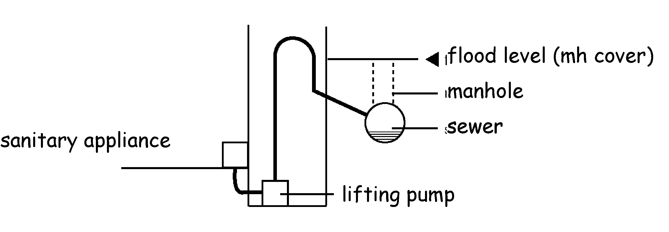
3.7.3 Drainage system outside a building
A drainage system outside a building, should be constructed and installed in accordance with the recommendations in BS EN 12056-1: 2000, BS EN 752: 2008 and BS EN 1610: 1998.
Reducing the bore of a drain in the direction of flow may lead to blockages and is not recommended.
Health and safety legislation requires that manual entry to a drain or sewer system is only undertaken where no alternative exists. Therefore use of remotely operated equipment will become the normal method of access. As well as the traditional inspection chambers used for depths of up to 1m, remotely operated equipment is available for inspection, cleaning and removal of debris from deeper drains and sewers, without the need for personal entry.
3.7.4 Connection to a public sewer
Where a private drain discharges into a public sewer, normally at the curtilage of a building, some form of access should be provided for maintenance and to allow a satisfactory connection. A disconnecting chamber (or manhole where the depth is more than 1.2m) should be provided in accordance with the requirements of Scottish Water in whom it is likely to be vested.
3.7.5 Conversions and extensions
Incorrect drainage connections, mostly related to conversions and extensions, whether wastewater to surface water or vice versa, is a common occurrence and can cause severe pollution of watercourses or surcharging of drains also leading to pollution. A careful check should be made before breaking into an existing drain to ensure it is the correct one and a further test carried out after connection, such as a dye test, to confirm correct connection.
3.7.6 Sewers intended for vesting
Where it is intended that a private sewer (a sewer connecting 2 or more buildings that are privately owned and maintained) will be vested in the Water Authority, construction and installation should be in accordance with the requirements of ‘Sewers for Scotland’.
3.7.7 Ventilation of a drainage system
A wastewater drainage system serving a building should be ventilated to limit the pressure fluctuations within the system and minimise the possibility of foul air entering the building. A system should be installed in accordance with the guidance in Sections 4, 5, 6 and National Annex ND of BS EN 12056-2: 2000.
Air admittance valves are another method of ventilating a drainage system as they allow air to enter the drainage system, but not to escape, thus limiting pressure fluctuations within the system. Care should be taken when installing these valves that they are located where they will operate effectively. Air admittance valves should be installed:
a.in accordance with the recommendations in BS EN 12380: 2002, or
b.in compliance with the conditions of certification of a notified body.
3.7.8 Discharges into a drainage system
Where a discharge into a drainage system contains oil, fat, grease or volatile substances, for example from a commercial kitchen, there should be facilities for the separation and removal of such substances. Separator systems are used in a wide variety of situations to fulfil a number of different requirements. It is important to establish why a separator system is needed and what specific function it is expected to fulfil before selecting the appropriate size and type of installation.
Separators should be constructed and installed in accordance with:
a.BS EN 858-2: 2003 for light liquids such as oil or petrol
b.BS EN 1825-2: 2002 for fat or grease.
The use of emulsifiers to break up any oil or grease in the drain is not recommended as they can cause problems further down the system.
3.7.9 Greywater recycling
Water reuse is becoming an accepted method of reducing demand on mains water and the use of greywater may be appropriate in some buildings for flushing of water closets. However because greywater recycling systems require constant observation and maintenance they should only be used in buildings where a robust maintenance contract exists.
Where a greywater system is to be installed it should be designed and installed in accordance with the Water Byelaws 2004, the Water Regulations Advisory Scheme (WRAS) Information and Guidance Notes 9-02-04 and 9-02-05, 1999 and the CIRIA publication CIRIA C539: ‘Rainwater and Greywater use in Buildings: Best Practice Guidance’. The system should also be designed, installed and commissioned by a person competent and knowledgeable in the nature of the system and the regulatory requirements. The approval of Scottish Water is needed before any such scheme is installed.
A risk assessment on the health and safety implications should be carried out for those who will be employed to install and maintain the system.
A comprehensive installation guide, users’ guide and an operation and maintenance manual should be handed to the occupier at the commissioning stage.
3.7.10 Testing
A wastewater drainage system should be tested to ensure the system is laid and is functioning correctly. Testing should be carried out in accordance with the guidance in:
a.National Annex NG of BS EN 12056-2: 2000, for sanitary pipework
b.BS EN 1610: 1998, for a drainage system under and around a building.
3.7.11 Wastewater discharge
A wastewater drainage system should discharge to a public sewer or public wastewater treatment plant provided under the Sewerage (Scotland) Act 1968, where it is reasonably practicable to do so.
Discharge of greywater may be via a water closet when the installation is in accordance with the guidance provided in clause 3.7.9.
Where it is not possible to discharge to a public system, for example in the countryside where there is no public sewer, other options are available, as described in the guidance to Standards 3.8 and 3.9: Private wastewater treatment systems.
3.8 Private wastewater treatment systems – treatment plants
#Source page 52
Mandatory Standard
| Standard 3.8 Every private wastewater treatment plant or septic tank serving a building must be designed and constructed in such a way that it will ensure the safe temporary storage and treatment of wastewater prior to discharge. |
3.8.0 Introduction
A wastewater treatment system is an effective, economical way of treating wastewater from buildings. It consists of 2 main components, a watertight underground tank into which raw sewage is fed and a system designed to discharge the wastewater safely to the environment without pollution. This is normally an infiltration field through which wastewater is released to the ground, but when ground conditions are not suitable, a discharge to a watercourse or coastal waters may be permitted. The infiltration field provides secondary treatment and is often critical for protecting the environment from pollution. Not all treatment plants treat to the same standard, for example, biological treatment plants treat the wastewater to a much higher standard than septic tanks prior to release of the wastewater thus reducing pollution and permitting a smaller infiltration field. As there are many different types of treatment plants with varying degrees of efficiency, then the type chosen should be selected for the effluent standard required to protect the environment.
Although a septic tank is a basic form of treatment plant, it has been specifically mentioned in the guidance to clarify the recommendations.
Package treatment plant is the term applied to a range of systems engineered to treat a given hydraulic and organic load using prefabricated components that can be installed with minimal site work.
Guidance on the construction and installation of drains discharging into private wastewater treatment plants or septic tanks is covered by Standard 3.7.
Conversions - in the case of conversions, as specified in regulation 4, the building as converted shall meet the requirements of this standard (regulation 12, schedule 6).
3.8.1 Treatment plants
Where it is not reasonably practicable to connect to a public sewer or a public wastewater treatment plant then discharge should be to a private wastewater treatment plant or septic tank.
Treatment plants provide suitable conditions for the settlement, storage and partial decomposition of solids that need to be removed at regular intervals. The discharge can however still be harmful and will require great care when discharging to ground to ensure a suitable level of protection of the environment is achieved. A large number of small sewage treatment works in a limited area is undesirable. The guidance to Standard 3.9 deals with the infiltration system that should be constructed as an integral part of the treatment plant or septic tank.
When sizing and selecting the wastewater treatment plant the designer should take full account of all population loadings, effluent treatment standard, and also where appropriate, any unusual pollution loads such as waste disposal units.
Use of detergents and disinfectants is not detrimental but excessive use may have a harmful effect on the performance of the sewage treatment works. The British Water Code of Practice, Flows and Loads – 2 (http://www.britishwater.co.uk/) provides guidance on sizing criteria and treatment capacity for small (maximum 1000 population equivalent) wastewater treatment systems.
A private wastewater treatment plant and septic tank should be designed, constructed and installed in accordance with:
a.the recommendations of BS EN 12566-1: 2000, for a prefabricated septic tank, or
b.the recommendations of BS 6297: 1983, or
c.the conditions of certification by a notified body.
3.8.2 Treatment plant covers
The settlement tank of a private wastewater plant and a septic tank should have a securely sealed, solid cover that is capable of being opened by 1 person using standard operating keys.
3.8.3 Inspection and sampling
A private wastewater plant and septic tank should be provided with a chamber for the inspection and sampling of the wastewater discharged from the tank. The owner should carry out inspection at regular intervals and SEPA can sample the effluent to ensure compliance with any discharge consent. A chamber should be provided in accordance with the following diagram.
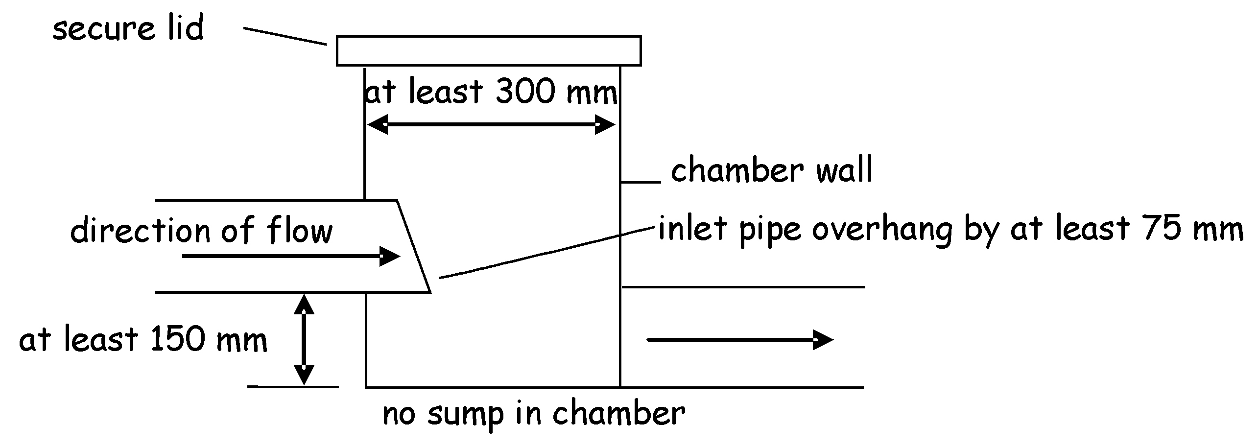
3.8.4 Location of a treatment plant
Research has shown that there are no health issues that dictate a safe location of a treatment plant or septic tank relative to a building. However damage to the foundations of a building has been shown to occur where leakage from the tank has occurred. In the unlikely event of there being leakage, it is sensible to ensure that any water bearing strata directs any liquid away from the building. To prevent any such damage therefore, every part of a private wastewater plant and septic tank should be located at least 5m from a building.
Every part of a private wastewater plant and septic tank should be located at least 5m from a boundary in order that an adjoining plot is not inhibited from its full development potential.
3.8.5 Discharges from septic tanks and treatment plants
Where mains drainage is not available, it may be possible to discharge treated wastewater to ground via an infiltration system, as described in clause 3.9.2, or to a water course, loch or coastal waters.
SEPA will require an authorisation, under the terms of the Water Environment (Controlled Activities)(Scotland) Regulations 2005 to be applied for all discharges of sewage effluent whether to ground via an infiltration system or to a watercourse.
3.8.6 Access for desludging
Wastewater treatment plants should be inspected monthly to check they are working correctly. The effluent in the outlet from the tank should be free flowing. The frequency of desludging will depend upon the capacity of the tank and the amount of waste draining to it from the building but further advice on desludging frequencies should be obtained from the tank manufacturer or the desludging contractor.
A private wastewater treatment plant and septic tank should be provided with an access for desludging. The desludging tanker should be provided with access to a working area that:
a.will provide a clear route for the suction hose from the tanker to the tank, and
b.is not more than 25m from the tank where it is not more than 4m higher than the invert level of the tank, and
c.is sufficient to support a vehicle axle load of 14 tonnes.
3.8.7 Labelling
Every building with a drainage system discharging to a private wastewater treatment plant or septic tank should be provided with a label to alert the occupiers to such an arrangement. The label should describe the recommended maintenance necessary for the system and should include the following:
‘The drainage system from this property discharges to a wastewater treatment plant (or septic tank, as appropriate). The owner is legally responsible for routine maintenance and to ensure that the system complies with any discharge consent issued by SEPA and that it does not present a health hazard or a nuisance’.
The label should be located adjacent to the gas or electricity consumer unit or the water stopcock.
3.9 Private wastewater treatment systems – infiltration systems
#Source page 53
Mandatory Standard
| Standard 3.9 Every private wastewater treatment system serving a building must be designed and constructed in such a way that the disposal of the wastewater to ground is safe and is not a threat to the health of the people in or around the building. |
3.9.0 Introduction
The intention of this standard is to ensure that non-mains drainage systems are designed and constructed to a standard so that the discharges from them do not contribute to environmental pollution and will achieve statutory environmental standards. Subject to discharge authorisation from SEPA, (see clause 3.8.5) wastewater from treatment systems can either discharge to land via an infiltration system or to watercourses, lochs or coastal waters. The guidance to this standard deals with discharges to land via infiltration systems. The infiltration method will form a critical part of the treatment system and care must be taken in the type, design and location chosen to avoid environmental pollution. The guidance to this standard should be used in conjunction with the guidance to Standard 3.8 when designing wastewater treatment systems.
Several hundreds of wastewater treatment systems are thought to cause pollution problems every year. These problems occur mainly because of poor location, poor drainage field design or lack of maintenance.
Conversions - in the case of conversions, as specified in regulation 4, the building as converted shall meet the requirements of this standard (regulation 12, schedule 6).
3.9.1 Assessing the suitability of the ground
An infiltration system serving a private wastewater treatment plant, septic tank or for greywater should be constructed in ground suitable for the treatment and dispersion of the wastewater discharged. This can be achieved by following the guidance below.
A ground assessment and soil percolation test should be carried out to determine the suitability of the ground. The following three step procedure should be followed:
First, carry out a preliminary ground assessment. The following check list indicates the actions that should be taken and the type of information that should be collected:
•consult SEPA, verifier and the Environmental Health Officer as required
•consult SEPAs latest groundwater protection policy
•identification of the underlying geology and aquifers
•whether the ground is liable to flooding
•nature of the sub-soil and groundwater vulnerability
•implication of plot size
•proximity of underground services
•ground topography and local drainage patterns
•whether water is abstracted for drinking, used in food processing or farm dairies
•implication for, and of, trees and other vegetation
•location of surface waters and terrestrial ecosystems.
The preliminary assessment may indicate that the ground is unsuitable for the installation of an infiltration system, in which case an alternative disposal method should be considered.
Second, a trial hole should be dug to determine the position of the water table and soil conditions. This trial hole will enable the sub-soil type to be determined. The trial hole should be a minimum of 2m deep, or a minimum of 1.5m below the invert of the proposed distribution pipes. The trial hole should be left covered for a period of 48 hours before measuring any water table level. Subsoils that overlay bedrock allow water to move through the pore spaces between the grains of material of which they are composed. They are the first line of defence against pollution and act as a protecting filtering layer. Where these materials are unsaturated, pollution attenuation processes are often enhanced. Water flows through much of Scotland’s bedrock via fissures. Attenuation of contaminants is limited in these cases. For safe and effective dispersal of the wastewater, the groundwater and bedrock should be at least 1m below the bottom of the distribution pipes. It should also be noted that it is the seasonally highest level of the water table that should be determined for the infiltration area.
Third, to determine the type of infiltration system and the area of ground required, percolation tests should be carried out. These percolation tests should be carried out using either of the following methods:
a.expert examination of the soil distribution analysis, using the method described in BS 1377: Part 2: 1990, or
b.expert in-situ testing using either the Constant Head or Tube Permeameter as described in CEN/TR 12566–2–2005, or
c.excavate a minimum of two percolation holes, not less than 5m apart along the line of and below the proposed invert level of the effluent distribution pipe. Each hole should be 300mm square to a depth of 300mm. Where deep drains are necessary, the holes should conform to this shape at the bottom but may be enlarged above the 300mm level to facilitate safe excavation. Fill the 300mm square section of the holes to a depth of at least 300mm with water and allow them to seep away overnight. It is important to saturate the soil surrounding the test holes to simulate day to day conditions in an operational drainage field. Next day, refill the test sections of the percolation holes with water to a depth of at least 300mm and observe the time (t) in seconds, for the water to seep away from 75% to 25% full level. Divide this time by 150mm. The answer gives the average time in seconds (Vp) required for the water to drop 1mm. Take care when making the tests to avoid unusual weather conditions such as heavy rain, severe frost or drought. To obtain consistent results carry out the test at least 3 times for each percolation hole and take the average figure.
The floor area of a sub-surface drainage trench required to disperse effluent from treatment plants or septic tanks may be calculated from the following formula:
A= P x Vp x 0.25
A - is the area of the sub-surface drainage trench, in m2
p - is the number of persons served by the tank and
Vp - is the percolation value obtained, as described above, in secs/mm.
For wastewater that has received the benefit of secondary treatment followed by settlement, this area may be reduced by 20%, i.e.
A = P x Vp x 0.2
3.9.2 Design of infiltration fields
An infiltration system serving a private wastewater treatment plant or septic tank should be designed and constructed to suit the conditions as determined by the ground into which the treated wastewater is discharged. An infiltration system should be designed and constructed in accordance with the following guidance:
Fast percolation rates - where the percolation value (as demonstrated by the percolation test) is not more than 15 secs/mm, in accordance with the requirements of SEPA
Normal percolation rates - where the percolation value (as demonstrated by the percolation test) is more than 15 secs/mm and not more than 100 secs/mm, as:
a.a piped infiltration trench system in accordance with national annex NA of BS EN 752: 2008, using perforated, rigid pipes with a smooth internal surface, or
b.a piped infiltration bed system in accordance with the diagram below, or
c.any system described under ‘slow and very slow percolation rates’.
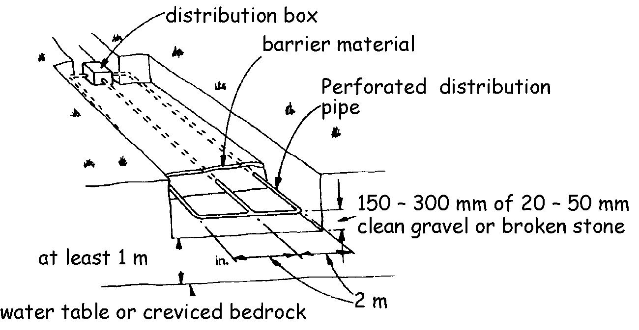
Where the percolation value (as demonstrated by the percolation test) is more than 100 secs/mm and not more than 140 secs/mm, as:
a.a reed bed complying with the requirements of the BRE, Good Building Guide, GBG 42, Parts 1 and 2 together with a piped infiltration system described in sub-clauses (a) and (b) with a normal percolation rate, or a suitable outfall, or
b.a constructed wetland, other than a reed bed, to a professionally prepared design and constructed by specialist contractor(s), or
c.a proprietary filtration system designed, constructed and installed in accordance with the conditions of a notified body, or
d.any other equivalent filtration system designed by a specialist in this subject and constructed by specialist contractor(s).
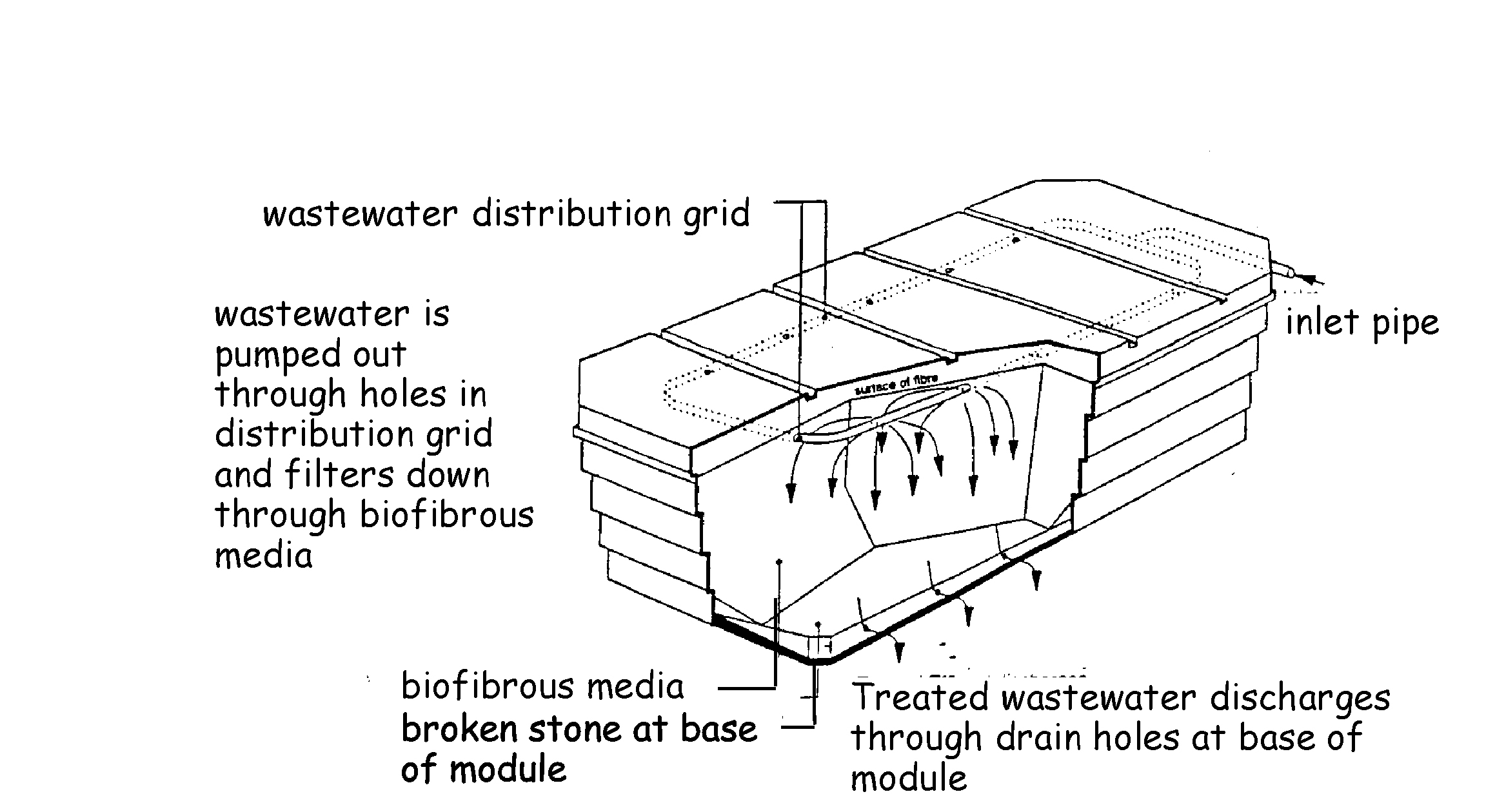
Very slow percolation rates - where the percolation value (as demonstrated by the percolation test) is more than 140 secs/mm:
a.as a system described under ‘slow percolation rate’ that does not use an infiltration system for the final treated wastewater, or
b.for domestic sized buildings, by designing and constructing a mound filter system in accordance with BR 478, Mound Filter Systems for the treatment of domestic wastewater'.
3.9.3 Greywater disposal
The disposal of greywater (from baths, showers, washbasins, sinks and washing machines) may be accomplished by an infiltration field the area of which can be calculated from the following:
A= P x Vp x 0.2
A - is the area of the sub-surface drainage trench, in m2
p - is the number of persons served, and
Vp - is the percolation value obtained, as described above, in secs/mm.
3.9.4 Location of infiltration fields – pollution
An infiltration system serving a private wastewater treatment plant or septic tank should be located to minimise the risk of pollution. An infiltration field should be located in accordance with the following guidance:
a.at least 50m from any spring, well or borehole used as a drinking water supply, and
b.at least 10m horizontally from any watercourse (including any inland or coastal waters), permeable drain, road or railway.
3.9.5 Location of infiltration fields – damage to buildings
Research has shown that there are no health issues that dictate a safe location of an infiltration field relative to a building. However damage to the foundations of a building is likely to occur where discharge is too close to the building. It is sensible to ensure that any water bearing strata directs any effluent away from the building.
To prevent any such damage therefore, every part of an infiltration system serving a private wastewater treatment plant or septic tank should be located at least 5m from a building. An infiltration system should also be located at least 5m from a boundary in order that an adjoining plot is not inhibited from its full development potential.
However the ground strata or permeability of the soil may influence this dimension and it may be reduced slightly where the strata directs any groundwater away from the foundations or if the soil is free draining. Indeed, to preserve the structural integrity of the building, it may be prudent to increase the dimension where ground conditions would allow wastewater to collect around the building's foundations.
3.10 Precipitation
#Source page 54
Mandatory Standard
| Standard 3.10 Every building must be designed and constructed in such a way that there will not be a threat to the building or the health of the occupants as a result of moisture from precipitation penetrating to the inner face of the building. Limitation: This standard does not apply to a building where penetration of moisture from the outside will result in effects no more harmful than those likely to arise from use of the building. |
3.10.0 Introduction
Rain penetration shows up as damp patches, usually after heavy rain, on the inside of external walls, around door or window openings or on ceilings. It can be difficult to pinpoint the exact route the rainwater is taking. For example, a damp patch on a ceiling could be the result of a faulty flashing or damaged felt on a flat roof some distance away from the damp patch.
Similarly, unless they have adequate damp proof courses and flashings, materials in parapets and chimneys can collect rainwater and deliver it to other parts of the dwelling below roof level. Penetration occurs most often through walls exposed to the prevailing wet winds, usually south-westerly or southerly. There is evidence that the amount of rainfall has increased across much of Scotland. In addition, the majority of research indicates that this trend may continue as a consequence of climate change.
There are numerous publications providing good practice guidance on methods of preventing rain penetration to internal surfaces of buildings. BRE book ‘Roofs and Roofing – performance, diagnosis, maintenance, repair and the avoidance of defects’ provides helpful guidance for building professionals to address these problematic issues.
Explanation of terms - the following terms are included to provide clarity to their meaning in the guidance to this standard.
A vented cavity means a cavity with openings to the outside air placed so as to allow some limited, but not necessarily through air movement. The openings are normally located at low level where they can also act as weep holes to drain water from the cavity.
A ventilated cavity means a cavity with openings to the outside air placed so as to promote through movement of air. The openings should be located at high and low level.
Conversions - in the case of conversions, as specified in regulation 4, the building as converted shall meet the requirements of this standard in so far as is reasonably practicable, and in no case be worse than before the conversion regulation 12, schedule 6).
3.10.1 General provisions
A floor, wall, roof or other building element exposed to precipitation, or wind driven moisture, should prevent penetration of moisture to the inner surface of any part of a building so as to protect the occupants and to ensure that the building is not damaged.
For external wall constructions it is important that the wall is designed and constructed to suit the degree of exposure to wind and rain that it may be subject to.
BS EN ISO 15927-3: 2009 and BS 8104: 1992 provide a range of methodologies for the assessment of wind driven rain on the walls of a building:
•BS EN ISO 15927-3: 2009 – This methodology, which is based closely on BS 8104, uses two procedures to analyse hourly wind and rain data, collected for any location over a minimum 10 year period, to calculate a driving rain index.
•BS 8104: 1992 – This methodology determines the degree of exposure of a wall by using historical wind and rain data mapped at specific locations across the country.
An alternative simplified approach is provided within BR 262 ‘Thermal Insulation: Avoiding the risks’. This document is based on BS 8104 and provides a map that indicates exposures zones.
Some types of buildings, such as carports or storage of outdoor equipment, can be unaffected by damp penetration and the following guidance therefore may not be relevant.
When using any of the constructions below, the following general recommendations should be followed for walls or roofs, as appropriate:
•masonry walls of bricks and/or blocks incorporating damp-proof courses, flashings and other materials and components constructed in accordance with the relevant recommendations of BS 5628: Part 3: 2001. The construction used should suit the degree of exposure to wind and rain as described in BS EN ISO 15927-3: 2009 or BS 8104: 1992
•masonry walls incorporating external rendering which conforms to the relevant recommendations of BS 5262: 1991, to suit the degree of exposure and the type of masonry
•masonry walls of natural stone or cast stone blocks constructed in accordance with the relevant recommendations of BS 5628: Part 3: 2005 and to suit the degree of exposure to wind and rain as described in BS EN ISO 15927-3: 2009 or BS 8104: 1992
•masonry cavity walls incorporating insulation material, either as a complete or partial cavity fill, where the insulating material is the subject of a current certificate issued under the relevant conditions of an independent testing body. The walls should be constructed in accordance with the terms of the certificate and to suit the degree of exposure to wind and rain as described in BS EN ISO 15927-3: 2009 or BS 8104: 1992 and the relevant recommendations of the following British Standards:
Table 3.3. Cavity wall insulation
| Materials or conditions | British Standards |
|---|---|
| Urea formaldehyde (UF) foam | BS 5617: 1985 and BS 5618: 1985 |
| Man-made mineral fibre (slabs) | BS 6676: Parts 1: 1986 |
| Assessment of walls for filling | BS 8208: Part 1: 1985 |
•roofs with copper, lead, zinc and other sheet metal roof coverings require provision for expansion and contraction of the sheet material. In 'warm deck' roofs, in order to reduce the risk of condensation and corrosion, it may be necessary to provide a ventilated air space on the cold side of the insulation and a high performance vapour control layer between the insulation and the roof structure. It may also be helpful to consult the relevant trade association
•walls or roofs incorporating cladding materials constructed in accordance with the recommendations of the following British Standards or Codes of Practice:
Table 3.4. Wall and roof cladding materials
| Materials and conditions | Element | British Standards and Codes of Practice |
|---|---|---|
| Aluminium | wall or roof | CP 143: Part 15: 1973 (1986) |
| Galv. corrugated steel | wall or roof | CP 143: Part 10: 1973 |
| Lead | wall or roof | BS 6915: 2001 |
| Copper | wall or roof | CP 143: Part 12: 1970 (1988) |
| Slates and tiles | wall or roof | BS 5534: Part 1: 2003 |
| Zinc | wall or roof | CP 143: Part 5: 1964 |
| Non-loadbearing walls | wall or steep roof | BS 8200: 1985 |
| PC concrete cladding | wall | BS 8297: 2000 |
| Natural stone cladding | wall | BS 8298: 1994 |
| Flat roofs | roof | BS 6229: 2003 |
| Bitumen felt | roof | BS 8217: 2005 |
| Mastic asphalt | roof | BS 8218: 1998 |
3.10.2 Wall constructions (solid, masonry)
The following sketches provide guidance on recommended methods of construction to prevent rain penetration to the inner surfaces of the building. The thickness and other dimensions quoted are the minimum recommended unless otherwise stated. Greater figures are therefore possible.
| Wall type A (solid wall with internal insulation) - solid wall, 200mm thick of bricks, blocks or slabs of clay, calcium silicate, concrete or cast stone. Wall rendered or unrendered externally. Insulation and plasterboard internally, with a cavity 25mm wide. | Figure 3.11. Wall constructions - Type A |
| Wall type B (solid wall with external insulation) - solid wall as (A) above. Insulation applied to the external surface of the wall; protected externally either by cladding (of sheets, tiles or boarding) with permanent ventilation, or by rendering. Wall with or without an internal surface finish of plaster or plasterboard. | Figure 3.12. Wall constructions - Type B |
3.10.3 Wall constructions (cavity, masonry)
| Wall type A (cavity wall with internal insulation) - cavity wall of 2 leaves of masonry separated by a 50mm cavity; each leaf, 100mm thick, of either bricks or blocks of clay, calcium silicate or concrete. Wall rendered or unrendered externally. Insulation applied as a lining to the internal surface of the wall and plasterboard. | Figure 3.13. Wall constructions - Type A |
| Wall type B (cavity wall with cavity fill insulation) - cavity wall as (A) above. Wall rendered or unrendered externally. Insulation applied as a cavity fill. Wall with or without an internal surface finish of plaster or plasterboard. This construction is only recommended for sheltered conditions. | Figure 3.14. Wall constructions - Type B |
| Wall type C (cavity wall with partial fill insulation) - cavity wall as (A) above. Wall rendered or unrendered externally. Insulation applied to either leaf as a partial cavity fill so as to preserve a residual space of 50mm wide. Wall with or without an internal surface finish of plaster or plasterboard. | Figure 3.15. Wall constructions - Type C |
3.10.4 Extensions
Careful consideration should be given to the detailing of an existing wall of a building when an extension is added. The outer leaf of a previously external wall will become an internal wall and any moisture that enters the cavity could collect and cause serious damage to the building. Where the building is located in an exposed location or where the existing construction might allow the passage of rain either through facing brick or a poorly rendered masonry wall, the use of a cavity tray along the line of the roof of the extension may be appropriate. However in sheltered situations or where the detailing can prevent damage to the building as a result of rain penetration a raggled flashing (chased into the wall) may be sufficient.
3.10.5 Wall constructions (framed)
| Wall type A (masonry cladding) - framed wall of timber studs and dwangs, with a vapour permeable sheathing to the framing covered with a breather membrane. Masonry external cladding of 100mm thick clay brick or block, concrete or calcium silicate brick or block, dense in-situ concrete, lightweight concrete or autoclaved aerated concrete, with an externally ventilated cavity in accordance with the guidance in clause 3.10.6. Masonry cladding rendered or unrendered externally. Insulation applied as an infill to the framing. The framing lined internally with a vapour control layer and plasterboard. | Figure 3.16. Wall constructions - Type A |
| Wall type B (weatherboarding, tile or slate cladding) - framed wall of timber studs and dwangs with a breather membrane. Cladding material, on battens and counter battens as required, of timber weather boarding, tile or slate. Insulation and internal lining as (A) above. | Figure 3.17. Wall constructions - Type B |
| Wall type C (sheet or panel cladding with/without ventilated cavity) - framed wall of timber or metal studs and dwangs. Sheet or panel cladding material of fibre cement, plastic, metal, GRP or GRC. Insulation applied either to the internal face of the framing with permanent ventilation behind any impervious cladding, or as an infill to the framing; in either case the wall lined internally with a vapour control layer and a lining. | Figure 3.18. Wall constructions - Type C |
3.10.6 Ventilation of wall cavities
Ventilation of external wall cavities is necessary to prevent the build-up of excessive moisture that could damage the fabric of a building. Ventilation holes can also be used to drain excess water from the cavity that has entered through the outer leaf.
Timber frame - interstitial condensation is one of the major problems that need to be addressed in timber framed buildings. To reduce the amount of interstitial condensation to a level that will not harm the timber frame or sheathing, a cavity of at least 50mm wide should be provided between the sheathing and the cladding. Where timber, slate or tile cladding is used, the width of the cavity should be measured between the sheathing and the inner face of the cladding, ignoring the battens and counter battens.
Where the outer leaf is of timber, slate or tile clad construction, a vented cavity should be provided. A ventilated cavity should be provided for extra protection in severely exposed areas. Where necessary refer to BS 8104: 1992. Due to the air gaps inherent between the components of a timber, slate or tile clad wall, no proprietary ventilators should be necessary and a 10mm free air space should be sufficient.
Cavity barriers - where the wall cavity is sub-divided into sections by the use of cavity barriers e.g. at mid-floor level in a 2 storey house, the ventilators should be provided to the top and bottom of each section of the cavity. Care should be taken with rendered walls to prevent blockage of the ventilators.
Masonry outer leaf - where the outer leaf is of masonry construction, venting of the cavity is normally sufficient. Cavities should be vented to the outside air by installing ventilators with at least 300mm2 free opening area at 1.2m maximum centres. Precipitation can penetrate the outer leaf of an external wall and cavities are normally drained through weep holes. These weep holes can also provide the necessary venting.
3.10.7 Roof constructions (flat)
The following sketches provide guidance on recommended methods of construction to prevent rain penetration to the inner surfaces of a building.
There is evidence to suggest that condensation in cold deck flat roofs can cause problems and these type of roofs should be avoided. Both the warm deck and warm deck inverted roof constructions, where the insulation is placed above the roof deck, are considered preferable. Further guidance is given to Standard 3.15 in the domestic Handbook.
The following British Standards give recommendations on the design and construction of flat roofs:
BS 6229: 2003 – CoP for flat roofs with continuously supported coverings
BS 6915: 2001 – CoP Design and construction of fully supported lead sheet roof and wall cladding
BS 8217: 2005 – CoP for reinforced bitumen membranes
BS 8218: 1998 – CoP for mastic asphalt roofing CP 143-12: 1970 – CoP for sheet and wall coverings
| Roof type A (concrete - warm roof) - flat roof structure of in-situ or precast concrete with or without a screed; with or without a ceiling or soffit. External weatherproof covering; with insulation laid on a vapour control layer between the roof structure and the weatherproof covering. [Note 1] | Figure 3.19. Roof constructions - Type A |
| Roof type B (concrete - inverted roof) - flat roof structure as (A) above. External protective covering; with low permeability insulation laid on a waterproof membrane between the roof structure and the external covering. | Figure 3.20. Roof constructions - Type B |
| Roof type C (timber or metal frame - warm roof) - flat roof structure of timber or metal-framed construction with a board decking 19mm thick; with or without a ceiling or soffit. External weatherproof covering, insulation and vapour control layer as (A) above. [Note 1] | Figure 3.21. Roof constructions - Type C |
| Roof type D (timber or metal frame - inverted roof) - flat roof structure as (C) above. External protective covering, insulation and waterproof membrane as (B) above. | Figure 3.22. Roof constructions - Type D |
| Roof type E (troughed metal decking - warm roof) - flat roof structure of timber or metal framed construction with a troughed metal decking; with or without a ceiling or soffit. External weatherproof covering and insulation and vapour control layer as (A) above. [Note 1] | Figure 3.23. Roof constructions - Type E Roof type F (troughed metal decking - inverted roof) - flat roof structure as (E) above. External protective covering, insulation and waterproof membrane as (B) above. Figure 3.24. Roof constructions - Type F |
| Note | |
|---|---|
| Roof types A, C and E are not suitable for sheet metal coverings that require joints to allow for thermal movement. See also sub-clause f of clause 3.10.1. |
3.10.8 Roof constructions (pitched)
BS 5534: 2003 gives recommendations on the design, materials, installation and performance of slates, tiles and shingles including, amongst others, information on rain and wind resistance. The British Standard also provides a comprehensive list of other British Standards covering other less common pitched roof coverings.
| Roof type A (slate or tiles - insulation on a level ceiling) - pitched roof structure of timber or metal framed construction. External weatherproof covering of slates or tiles on under slating felt with or without boards or battens. | Figure 3.25. Roof constructions - Type A |
| Roof type B (slate or tiles - insulation on a sloping ceiling) - pitched roof structure as (A) above. External weatherproof covering as (A). | Figure 3.26. Roof constructions - Type B |
| Roof type C (slate or tiles - insulation on decking) - pitched roof structure as (A) above with a decking of low permeability insulation fitted to and between the roof framing. External weatherproof covering of slates or tiles, with tiling battens and counter battens (located over roof framing), and a breather membrane laid on the insulation decking; with a sloping ceiling. | Figure 3.27. Roof constructions - Type C |
| Roof type D (metal or fibre cement sheet - sandwich insulation) - pitched roof structure as (A) above. External weatherproof covering of metal or fibre cement sheet sandwich construction laid on purlins; with insulation sandwiched between the external and soffit sheeting; and with or without a ceiling. [Note 2] | Figure 3.28. Roof constructions - Type D |
Note 2
Roof type D is not suitable for sheet metal coverings that require joints to allow for thermal movement. See also sub-clause f of clause 3.10.1.
3.11 Facilities in dwellings
#Source page 55
Mandatory Standard
| Standard 3.11 Every building must be designed and constructed in such a way that: Limitation: This standard applies only to a dwelling. |
3.11.0 Introduction
This standard does not apply to buildings other than dwellings.
3.12 Sanitary facilities
#Source page 56
Mandatory Standard
| Standard 3.12 Every building must be designed and constructed in such a way that sanitary facilities are provided for all occupants of, and visitors to, the building in a form that allows convenience of use and that there is no threat to the health and safety of occupants or visitors. |
3.12.0 Introduction
It is important that sanitary facilities address the needs of occupants and visitors, both in terms of availability and accessibility. Facilities should be sufficient in number to prevent queuing, other than in exceptional circumstances. Variety in the range of provision will assist not only people with a mobility or sensory impairment but also benefit older people, those with babies or young children or encumbered by luggage.
Sanitary accommodation should not be an afterthought in the planning of a building, as this can result in facilities that are small or in awkward locations, making them difficult to access and use. Common issues include screening of the facilities that results in small lobbies and the use of white finishes, sanitary facilities and fittings to suggest cleanliness, creating difficulty for a person with a visual impairment.
Whilst guidance is offered on a variety of building types, some may not be categorised easily. In such cases, designers will need to discuss specific provision with client and user groups and consider the guidance given under this standard to arrive at a practical solution.
Changing Places Toilet (CPT) – is a toilet with a changing facility that is suitable for use by people that have profound and multiple learning disabilities or other disabilities and for whom standard accessible toilets may not be fit for purpose. A CPT is provided where the building owner chooses to do so and their installation represents best practice.
To be registered on the Changing Places’ national register all new CPTs need to meet the standards specified by the Changing Places Consortium (CPC). Meeting the consortium's standards will mean that registered facilities should meet the needs and expectations of the people who use them as well as their carers.
The human body absorbs lead easily from drinking water and this can have a negative effect on the intellectual development of young children. Although mains water supplies do not contain significant levels of lead, recent research studies have shown that leaded solder plumbing fittings, normally used for heating systems, have been used on drinking water pipework in contravention of the Scottish Water Byelaws 2004. Further guidance can be obtained from Scotland and Northern Ireland Plumbing Employers Federation (SNIPEF) http://www.snipef.co.uk/ and Scottish Water http://www.scottishwater.co.uk/.
Conversions - in the case of conversions as specified in regulation 4, the building as converted shall meet the requirement of this standard (regulation 12, schedule 6).
3.12.1 Number of sanitary facilities
The number of sanitary facilities provided within a building should be calculated from the maximum number of persons the building is likely to accommodate at any time, based upon the normal use of the building.
Separate male and female sanitary accommodation is usually provided. This should be based upon the proportion of males and females that will use a building, where this is known, or provide accommodation for equal numbers of each sex otherwise.
Unisex sanitary accommodation may be provided where each sanitary facility, or a WC and wash hand basin, is located within a separate space, for use by only one person at a time, with a door that can be secured from within for privacy.
Small businesses - in small premises, it is recognised that duplication of sanitary facilities may not always be reasonably practicable and that they might be shared between staff and customers. However where practicable, it is good practice for sanitary facilities for staff involved in the preparation or serving of food or drink to be reserved for their sole use, with a separate provision made for customers. Separate hand washing facilities for such staff should always be provided.
Changing Places Toilets (CPTs) - There is no requirement to provide a CPT in terms of building regulations, however, where a CPT is proposed the following guidance should assist the design and construction.
There are many building types best suited for CPT installations including publicly accessible facilities such as shopping malls, entertainment or assembly buildings and transport related facilities. Provision of CPTs within suitable buildings is important to establish a network of facilities at appropriate locations across the country.
A typical CPT installation should include the following key elements:
•adequate space (12m²) to allow a user to be assisted by carers
•a minimum ceiling height of 2.4m
•a wall or ceiling mounted tracking hoist
•a centrally placed WC with space either side for the carers
•a height adjustable wash hand basin
•a non-slip floor finish
•a door with a minimum clear opening width of 1m
•the provision of a shower may also be appropriate within certain buildings such as leisure centres.
In addition to the building related elements, a fully equipped CPT relies on the installation of additional equipment and specialist fittings, such as a height adjustable adult sized changing bench (minimum length 1.8m).
When altering or converting existing buildings, particularly historical buildings, it may be impractical to provide a CPT that achieves all of the above key elements. In such cases alternative solutions, that still meet the needs of most users and their carers may be considered. Early consultation with the Changing Places Consortium will be beneficial in these cases. Further information, including a specification, can be found at the website of the Changing Places Consortium (www.changing-places.org) and BS 8300: 2009.
CPTs should generally not be installed instead of accessible sanitary accommodation (see clause 3.12.7).
Schools - the numbers of sanitary facilities in schools should be provided in accordance with the tables in the School Premises (General Requirements and Standards) (Scotland) Regulations 1967, as amended. The recommendations within BS 6465-1: 2006 may also be helpful. However the School Premises Regulations do not address accessible sanitary facilities which therefore should be provided in accordance with the guidance to this standard.
Specialist buildings - a building providing a service registered or proposing to register under the Regulation of Care (Scotland) Act 2001, such as residential care buildings, day care centres and hospices, may be subject to additional standards set out in the relevant National Care Standards document for that service.
Accessible toilets should be provided within the overall number of sanitary facilities recommended in the various tables in the guidance to this standard, as either:
•at least 1 unisex accessible toilet, accessed independently from any other sanitary accommodation, or
•where provided within separate sanitary accommodation for males and females, at least 1 accessible toilet for each sex.
The number required will be dependent upon travel distances within a building to an accessible toilet.
3.12.2 Provision for staff
A building should be provided with sanitary facilities for staff in accordance with the following table:
Table 3.5. Number of sanitary facilities for staff
| Sex | Staff numbers | WC | WHB | Urinals |
|---|---|---|---|---|
| Male | 1 to 15 | 1 | 1 | 1 |
| 16 to 30 | 2 | 2 | 1 | |
| 31 to 45 | 2 | 2 | 2 | |
| 46 to 60 | 3 | 3 | 2 | |
| 61 to 75 | 3 | 3 | 3 | |
| 76 to 90 | 4 | 4 | 3 | |
| 91 to 100 | 4 | 4 | 4 | |
| over 100 | 1 additional WC, WHB and urinal for every additional 50 males or part thereof | |||
| Female (also male where no urinals provided) | 1 to 5 | 1 | 1 | |
| 6 to 25 | 2 | 2 | ||
| Over 25 | 1 additional WC and WHB for every additional 25 females (or males), or part thereof |
3.12.3 Provision in residential buildings
Public expectation of facilities in residential buildings has risen considerably over the years and en suite sanitary facilities now tends to be normal practice, though it is recognised that this may not be possible in all cases.
Where sanitary accommodation is not en suite to bedrooms, it should be located directly off a circulation area, close to bedrooms and provided in accordance with the following table:
Table 3.6. Number of sanitary facilities in residential buildings
| Sanitary facility | Number of sanitary facilities |
|---|---|
| WC | 1 per 9 persons, or part thereof |
| WHB | 1 per bedroom [1] |
| Bath or shower | 1 per 4 persons, or part thereof [2] |
Additional information:
1.For bedrooms, a wash hand basin should be en suite. An alternate ratio of 1 wash hand basin per four persons, or part thereof, may be used for dormitory sleeping accommodation.
2.Sanitary accommodation containing a bath or shower should also contain a WC and wash hand basin, in addition to the general provision for those sanitary facilities noted in the table.
In a residential building, an accessible bedroom (see clause 4.2.9) should be provided with accessible sanitary accommodation. This should comprise of a WC, wash hand basin and a bath or shower and should be en suite to each accessible bedroom, other than:
•when altering or converting an existing building, where it is not reasonably practicable to provide en suite sanitary accommodation, or
•where sanitary facilities need to be kept separate for safety reasons, such as in a place of lawful detention.
Where accessible sanitary accommodation is not en suite, it should be located directly off a circulation area, close to any accessible bedroom, and should be clearly identified.
3.12.4 Provision for public in shops and shopping malls
Sanitary accommodation for customers within shops and shopping malls should be clearly identified and located so that it may be easily reached. It should be provided on the entrance storey and, in larger buildings of more than 2 storeys, with a total sales floor area greater than 4,000m2, on every alternate storey. Provision should be as follows:
Table 3.7. Number of sanitary facilities for people, other than staff, in shops
| Building type | Sex | Sales area of shop | Waterclosets | Urinals |
|---|---|---|---|---|
| Shops (Class 1) and shopping malls | unisex | 500m2-1000m2 | 1 | |
| male | 1001m2-2000m2 | 1 | 1 | |
| 2001m2-4000m2 | 1 | 2 | ||
| over 4000m2 | plus 1 WC for each extra 2000m2 of sales area, or part thereof | plus 1 urinal for each extra 2000m2 of sales area, or part thereof | ||
| female | 1000m2-2000m2 | 2 | ||
| 2001m2-4000m2 | 5 | |||
| over 4000m2 | plus 2 WC for each extra 2000m2 of sales area, or part thereof | |||
| Shops (Class 2) and shopping malls | male | 1000m2-4000m2 | 1 | 1 |
| over 4000m2 | plus 1 WC for each extra 3000m2 of sales area, or part thereof | plus 1 urinal for each extra 3000m2 of sales area, or part thereof | ||
| female | 1000m2-2000m2 | 1 | ||
| 2001m2-4000m2 | 3 | |||
| over 4000m2 | plus 1 WC for each extra 3000m2 of sales area, or part thereof |
Additional information:
1.For the purposes of this guidance, shop sales areas are classified as: C1: (other than those listed under Class 2): supermarkets and department stores (all sales areas); shops for personal services such as hairdressing; shops for the delivery or uplift of goods for cleaning, repair or other treatment or for members of the public themselves carrying out such cleaning, repair or other treatment. C2: shop sales areas in shops trading predominantly in furniture, floor coverings, cycles, perambulators, large domestic appliances or other bulky goods or trading on a wholesale self-selection basis.
2.1 wash hand basin should be provided for each WC, plus 1 wash hand basin per 5 urinals, or part thereof.
3.For shopping malls, the sum of the sales areas of all the shops in the mall should be calculated and used with this table. Sanitary facilities provided within a shop may be included in the overall calculation.
4.If a shop has a restaurant or cafe, additional sanitary facilities to serve the restaurant should be provided, in accordance with clause 3.12.5.
5.Provision of sanitary accommodation for customers is not sought in shops below the area limits given above. However below these limits, an accessible toilet provided for staff should be located so that is available for use by customers where this is reasonably practicable.
3.12.5 Provision for public in entertainment & assembly buildings
It is not realistic to include every type of entertainment building and assembly building in the table below. Basic assumptions and reasonable deductions have to be made that best apply to the development under consideration. Provision should be in accordance with the following table:
Table 3.8. Number of sanitary facilities for the public in entertainment and assembly buildings
| Building type [2] | Sex | Number of people | Number of WCs [1] | Number of urinals [1] |
|---|---|---|---|---|
| Buildings used for assembly or entertainment (e.g. places of worship, libraries, cinemas, theatres, concert halls and premises without licensed bars) | male [5] | 1-100 | 1 | 2 |
| 101-250 | 1 | plus 1 for each extra 80 males, or part thereof, over 100 | ||
| over 250 | plus 1 for each extra 500 males, or part thereof | plus 1 for each extra 80 males, or part thereof, over 100 | ||
| female [5] | 1-40 | 3 | ||
| 41-70 | 4 | |||
| 71-100 | 5 | |||
| over 100 | plus 1 for each extra 35 females, or part thereof | |||
| Restaurants, cafés, canteens, fast food outlets (where seating is provided) and takeaway food shops [8] (where seating for more than 6 customers is provided for the consumption of food) | male | 1-10 | See note 6 | |
| 11-400 [7] | 1 for every 100, or part thereof | 1 per 50 males, or part thereof | ||
| over 400 | plus 1 for each extra 250 males, or part thereof | |||
| female | 1-10 | See note 6 | ||
| 11-20 | 2 | |||
| 21-50 | 3 | |||
| 51-100 | 4 | |||
| 101-150 | 5 | |||
| 151-200 | 6 | |||
| over 200 | plus 1 for each extra 100 females, or part thereof | |||
| Public houses and licensed bars [10, 11] | male [9] | 1-75 | 1 | 2 |
| 76-150 | 1 | 3 | ||
| over 150 | plus 1 for each extra 150 males, or part thereof | plus 1 for each extra 75 males, or part thereof | ||
| female [9] | 1-10 | 1 | ||
| 11-25 | 2 | |||
| over 25 | plus 1 for each extra 20 females, or part thereof | |||
| Swimming pools (bathers only) [12] | male | 1-100 | 2 | 1 per 20 males |
| over 100 | plus 1 for each extra 100 males, or part thereof | |||
| female | 1-25 | 2 | ||
| over 25 | plus 1 for each extra 25 females, or part thereof |
Additional information:
1.1 wash hand basin should be provided for each watercloset, plus 1 wash hand basin per 5 urinals, or part thereof.
2.In multi-use buildings, each function should be treated separately when calculating overall provision.
3.Where members of the public are permitted to use sanitary facilities provided for staff, a separate calculation should be made for each group and the total number of sanitary facilities provided accordingly.
4.There is no requirement to provide sanitary facilities for people other than staff in offices, industrial or storage buildings, but where they are provided, they should be readily accessible to the public, e.g. off the entrance hall or foyer.
5.In cinema-multiplexes and similar premises where the use of sanitary facilities will be spread through the opening hours, the level of sanitary facilities should normally be based upon 75% of total capacity. For single-screen cinemas, 100% occupancy is assumed.
6.One unisex WC may be installed for use by both male and female customers for up to and including 20 persons.
7.In the case of works and office canteens, the scale of provision may be reduced proportionally where there are readily accessible workplace sanitary facilities close to the canteen.
8.A takeaway food shop is a retail unit that serves hot or cold food, primarily for consumption off the premises, either solely or ancillary to its main use.
9.Number of customers should be calculated at the rate of 4 persons per 3m2 of effective drinking area (i.e. the total space of those parts of those rooms to which the public has access).
10.Public houses with restaurants should be provided with sanitary facilities as for licensed bars.
11.Public houses with public music, singing and dancing licenses should be as for licensed bars. The licensed area for public music, singing and dancing should be separated for calculation of numbers of persons and the provision of sanitary facilities for this area should be in accordance with buildings used for public entertainment.
12.Sanitary facilities for spectators should be provided in accordance with buildings used for public entertainment.
3.12.6 General provisions in all sanitary accommodation
Provisions made within sanitary accommodation will affect the degree to which the needs of building users are addressed in terms of safety, ease of use and hygiene. To ensure that these issues are addressed, the following provisions should be made within all sanitary accommodation:
•sanitary facilities, fittings and surface finishes should be easily cleanable, to allow a hygienic environment to be maintained, and
•to allow space for general use, where a door opens into a space containing a sanitary facility, there should be an unobstructed space of at least 450mm in diameter between the sanitary facility and the door swing (see diagram below), and
•a door fitted with a privacy lock should have an emergency release, operable from the outside and, if not sliding or opening outward, offer an alternate means of removal, to permit access in an emergency, and
•a sanitary facility and any associated aid or fitting, such as a grab rail, should contrast visually with surrounding surfaces to assist in use by a person with a visual impairment.
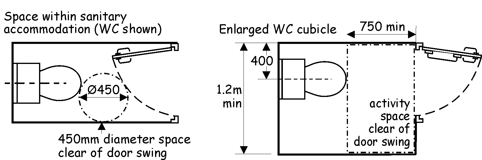
In addition to the points noted above, every toilet should:
•for personal hygiene, have a wash hand basin within either the toilet itself or in an adjacent space providing the sole means of access to the toilet, and
•to assist in general hygiene, be separated by a door from any room or space used wholly or partly for the preparation or consumption of food. However this need not be provided to a WC in a place of lawful detention, such as integral sanitary facilities within a prison cell, and
•to meet food hygiene regulations, not open directly on to any room or space used wholly or partly for the preparation or consumption of food on a commercial basis. This is most commonly addressed by providing an intervening ventilated space between a toilet and such a space, and
•to give variety in provision, including at least one enlarged WC cubicle, as shown below, where sanitary accommodation contains four or more WC cubicles in a range (see diagram above).
In addition, every bathroom or shower room should have a floor surface that minimises the risk of slipping when wet.
3.12.7 General provisions in accessible sanitary accommodation
Space provision within accessible sanitary accommodation is based primarily upon that needed to accommodate a person in a wheelchair, though this will also offer greater amenity to a wide range of other building users and better allow for assisted use.
Space for manoeuvring and the positioning and relationship of sanitary facilities and assistive aids are the key elements that will allow convenient use of accessible sanitary facilities, with or without assistance and in privacy. At least one sanitary facility of each type provided within a building should be within accessible sanitary accommodation.
Toilets - in addition to the general provisions in clause 3.12.6, accessible sanitary accommodation should:
•be clearly identified by signage as accessible sanitary accommodation, and
•contain a manoeuvring space of at least 1.5m by 1.5m, clear of any obstruction, including a door swing, other than a wall-mounted wash hand basin which may project not more than 300mm into this space, and
•be fitted with fixed and folding grab rails, as shown in the relevant diagram below. Rails should be securely fixed to walls and capable of accommodating the transfer weight of an adult, and
•be fitted with an assistance alarm which can be operated or reset when using a sanitary facility and which is also operable from floor level. The alarm should have an audible tone, distinguishable from any fire alarm, together with a visual indicator, both within the sanitary accommodation and outside in a location that will alert building occupants to the call, and
•where more than one accessible sanitary facility of a type is provided within a building, offer both left and right hand transfer layouts to allow choice in use by a person who favours a particular transfer method.
Coat hooks, mirrors, toilet paper dispensers and other fixtures that may further assist in use of accessible sanitary accommodation are outwith the remit of the building standards. Advice on provision and location may be found in BS 8300: 2001.
Provision in existing and historic buildings - when altering existing buildings, particularly historical buildings, it may be impractical to provide accessible sanitary accommodation of a size and form equivalent to that described in guidance. In such cases, alternate accommodation that still permits independent use by most wheelchair users, may be considered.
3.12.8 Accessible toilets
An accessible toilet should be provided in any building with toilet facilities. There should be an accessible toilet at any location where other toilets are provided, unless all occupied parts of the building lie within the travel distance, noted in clause 3.12.9, to another accessible toilet elsewhere in the building.
In addition to the recommendations within clauses 3.12.6 and 3.12.7, an accessible toilet should include a WC with:
•a seat height of 480mm, to assist in ease of transfer to and from a wheelchair, and
•a flush lever fitted to the transfer side of the cistern.
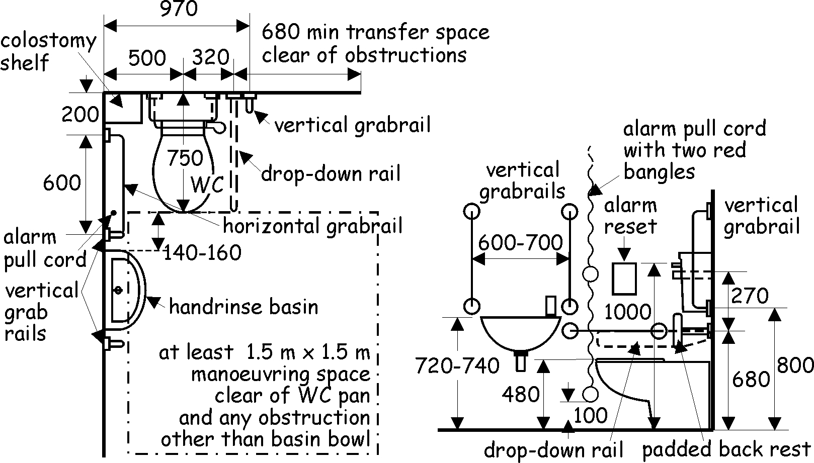
3.12.9 Location of accessible toilets
The time taken to get to an accessible toilet is an important factor to be considered when positioning such sanitary facilities within a building. They should be located where they can be reached easily and the horizontal distance from any part of a building to an accessible toilet should be not more than 45m.
Where there are no toilets on a storey, all occupied parts of that storey should be within 45m of the nearest accessible toilets on an adjacent storey. Any vertical travel by lift need may be discounted but should be limited to one storey.
Where areas within a building are not accessible at certain times, such as where classroom blocks are locked out of hours in a community school, the effect of this on travel distance should taken into account when positioning accessible toilets.
Where people are moving around, such as within the retail area of a large superstore or the concourse of a shopping mall, their distance from an accessible toilet will vary. In such areas, the travel distance may be increased to not more than 100m, provided there are no barriers, such as pass doors or changes of level on the route and the location of the accessible toilet is well signposted. However where people congregate in such areas, such as at a reception desk or at café seating, travel distance should remain not more than 45m.
3.12.10 Accessible bathrooms and shower rooms
The availability of accessible sanitary facilities is particularly important within residential buildings or sports facilities, where bathing or showering form an integral part of activities. A person should be able to use such sanitary facilities in privacy, with or without assistance.
In a building where baths or showers are provided, accessible sanitary accommodation should be provided at a ratio of 1 in 20 or part thereof, for each type of sanitary facility provided.
In addition to the recommendations within clauses 3.12.6 and 3.12.7, an accessible shower room or bathroom should:
•for a bath, include a transfer space of at least 400mm across the full width of the head of the bath, and
•for a shower, have a dished floor of a gradient of not more than 1:50 discharging into a floor drain, or a proprietary level access shower with a drainage area of not less than 1.2m by 1.2m, and
•for a shower, have a folding shower seat positioned 500mm from a flanking wall and securely fixed, with a seat height that permits transfer to and from a wheelchair positioned outwith the showering area.
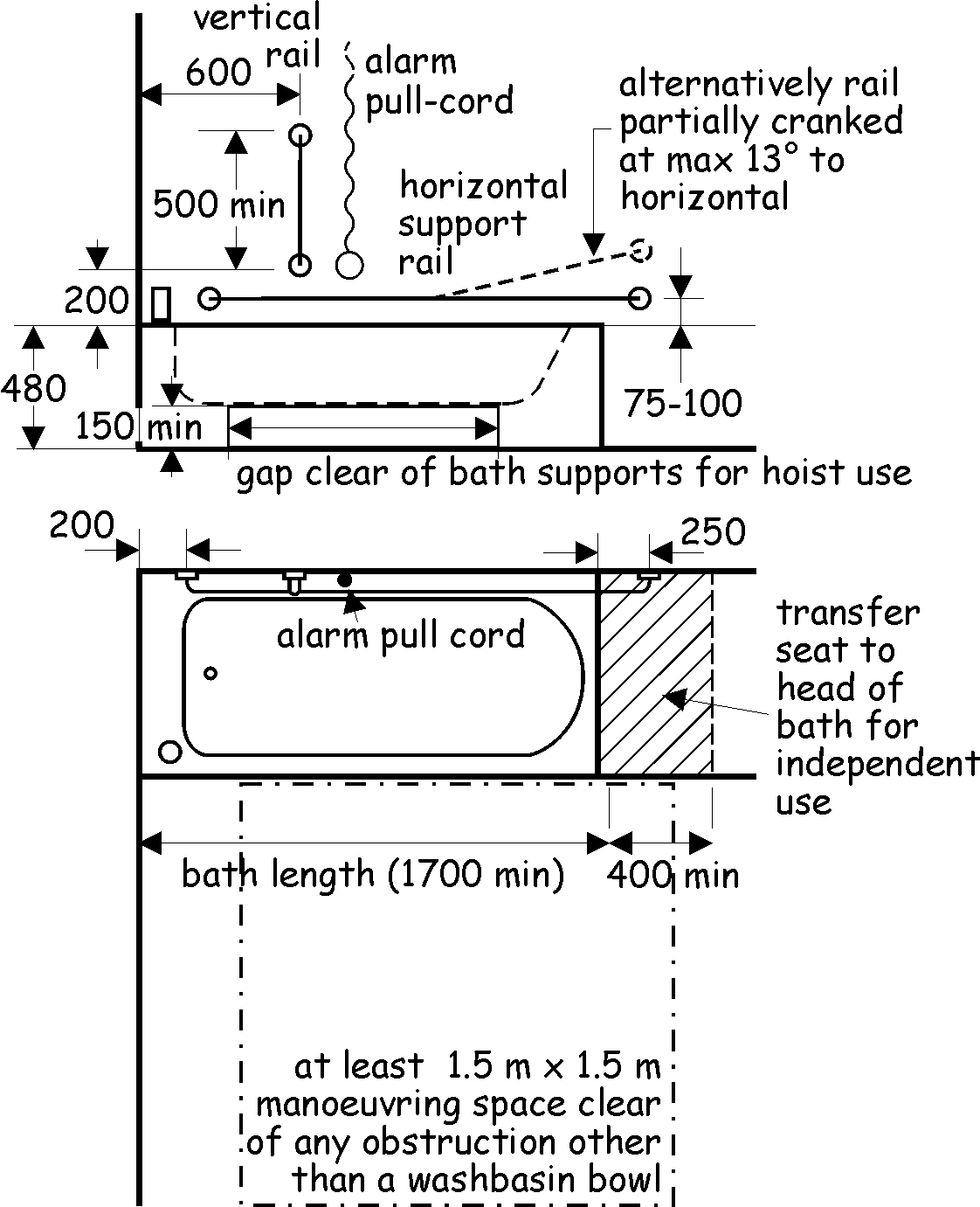
For most people, a level access shower is generally both easier and more convenient to use than a bath and, therefore, should always be included within a building where sanitary facilities for bathing are provided. An accessible shower should be separate or screened from other accommodation, to allow privacy when bathing.
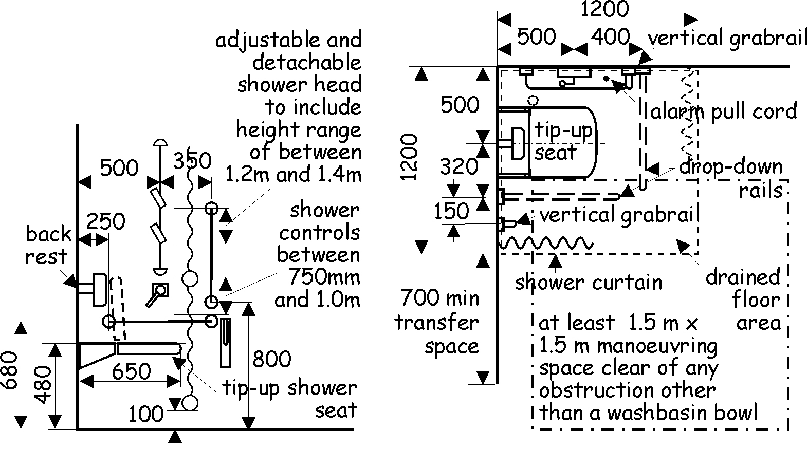
Communal showering areas - in addition, a shower area without separating cubicles, such as found within sporting facilities, which comprises of 10 or more showers should include at least one communal shower with the above provisions.
Separate toilet facilities - to avoid undue waiting times, where an accessible bath or shower is combined with accessible toilet facilities, there should also be a separate accessible toilet provided within the travel distance specified in clause 3.12.9.
3.12.11 Accessible changing facilities
As with bathing or showering, the accessibility of changing facilities is particularly important where forming an integral part of activities, such as in sporting facilities, staff changing areas in a place of work or for customers within a clothing shop.
Where individual facilities for changing are provided in a building, at least 1 cubicle in 20, or part thereof, should be of a size and form that will allow use by a wheelchair user, and follow the recommendations within clause 3.12.7. An accessible changing facility should be separate or screened from other accommodation to allow privacy when changing.
Communal changing - in addition, a changing area without separating cubicles, such as found within sporting facilities, to which the public have access and which is intended to accommodate 20 or more people should also include provision for accessible communal changing.
Combine facility - for convenience of use, an accessible changing facility may be combined with an accessible bathing or showering facility to give a combined facility offering privacy in bathing and dressing. In such cases, where a shower is provided, a second fold down seat should be fitted outwith the showering area and manoeuvring space to assist in drying and changing.
Where changing facilities incorporate fixed furniture such as lockers for clothing or personal effects, those assigned to accessible facilities should be positioned within 1.0m of floor level.
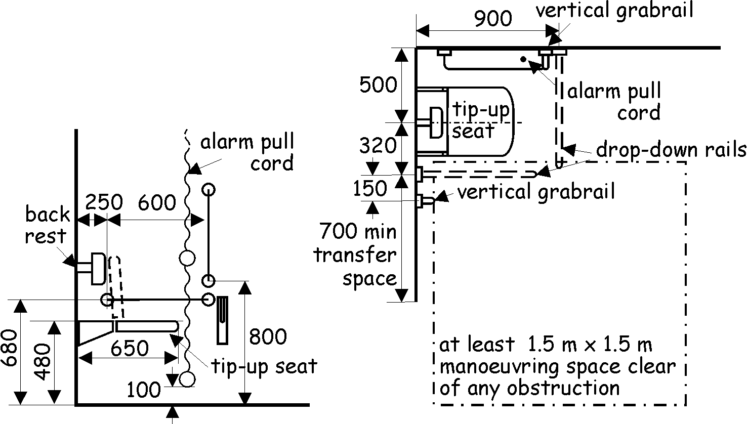
3.12.12 Baby changing facilities
In principle, a changing facility for babies should be provided in any building open to the public where such children will usually be present, such as in shops, assembly buildings and entertainment buildings. It is important that such facilities are accessible, both to accommodate a pram or buggy and to permit use by a person with mobility impairment.
Accommodating such a facility within smaller buildings may not be reasonably practicable and, in recognition of this, it need not be provided in all such buildings. However there should be baby changing facilities in:
•a shop or shopping mall with a total shop floor area of more than 1000m2, or
•an assembly building accommodating more than 200 people, or
•an entertainment building, including a restaurant, fast food outlet with seating or a licensed premises, accommodating more than 200 people.
If baby changing facilities are located within a toilet, they will reduce the number of available toilets within a building when in use. Where the toilet in question is also the only accessible toilet, this can cause additional inconvenience.
Baby changing facilities should be provided either as a separate unisex facility or as a dedicated space within both male and female sanitary accommodation and not within an accessible toilet and should contain:
•a manoeuvring space of at least 1.5m by 1.5m, clear of any obstruction, including a door swing, other than those noted below, and
•a wash hand basin at height of between 720mm and 740mm above floor level. A wall-mounted wash hand basin may project not more than 300mm into the manoeuvring space, and
•a changing surface at a height of approximately 750mm, with a clear space of not less than 700mm high beneath. This surface may overlap with a manoeuvring space by not more than 300mm.
3.13 Heating
#Source page 57
Mandatory Standard
| Standard 3.13 Every building must be designed and constructed in such a way that it can be heated and maintain heat at temperature levels that will not be a threat to the health of the occupants. Limitation: This standard applies only to a dwelling. |
3.13.0 Introduction
This standard does not apply to buildings other than dwellings.
3.14 Ventilation
#Source page 58
Mandatory Standard
| Standard 3.14 Every building must be designed and constructed in such a way that ventilation is provided so that the air quality inside the building is not a threat to the building or the health of the occupants. |
3.14.0 Introduction
Ventilation of a building is required to maintain air quality and so contribute to the health and comfort of the occupants. Without ventilation it is possible that carbon dioxide, water vapour, organic impurities, smoking, fumes and gases could reduce the air quality by humidity, dust and odours and also reduce the percentage of oxygen in the air to make the building less comfortable to work or live in.
Well designed natural ventilation has many benefits, not least financial and environmental, although it is also recognised that inside air quality can only be as good as outside air quality and in some cases filtration may be necessary. In other cases mechanical systems or systems that combine natural with mechanical (hybrid) may provide the ventilation solution for the building.
Ventilation can also have a significant affect on energy consumption and performance and so thorough assessment of natural, as against mechanical ventilation, should be made, as the decision could significantly affect the energy efficiency of the building (see Section 6, Energy).
Ventilation should not adversely affect comfort and, where necessary, designers might wish to consider security issues and protection against rain penetration prevalent in naturally ventilated buildings when windows are partially open to provide background ventilation.
Reducing air infiltration - improved insulation and ‘tighter’ construction of buildings will reduce the number of natural air changes but can increase the risk of condensation. However leaky buildings are draughty and uncomfortable. Sealing up air leaks improves comfort and saves energy whilst proper ventilation keeps the indoor air pleasant and healthy. If poor attention to detail occurs air leakage can account for a substantial part of the heating costs. Energy savings from building ‘tighter’ could make significant savings on energy bills. There is a common perception that ‘tight’ construction promotes indoor air pollution. However both ‘tight’ and 'leaky' buildings can have air quality problems. Though air leaks can dilute indoor pollutants, there is no control over how much leakage occurs, when it occurs or where it comes from. BRE GBG 67, ‘Achieving air tightness: General principles’ provides useful guidance on how to build new buildings tighter.
Conversions - in the case of conversions, as specified in regulation 4, the building as converted shall meet the requirement of this standard (regulation 12, schedule 6).
3.14.1 Ventilation generally
A building should have provision for ventilation by either:
a.natural means, or
b.mechanical means, or
c.a combination of natural and mechanical means (mixed-mode).
Ventilation is the process of supplying outdoor air to an enclosed space and removing stale air from the space. It can manage the indoor air quality by both diluting the indoor air with less contaminated outdoor air and removing the indoor contaminants with the exhaust air. Ventilation should have the capacity to:
•provide outside air to maintain indoor air quality sufficient for human respiration
•remove excess water vapour from areas where it is produced in sufficient quantities in order to reduce the likelihood of creating conditions that support the germination and growth of mould, harmful bacteria, pathogens and allergies
•remove pollutants that are a hazard to health from areas where they are produced in significant quantities
•rapidly dilute pollutant odours, where necessary.
Additional ventilation provision - this guidance relates to the provision of air for human respiration and is in addition to, and should be kept separate from, any air supply needed for the smoke ventilation of escape routes in the case of fire (Section 2, Fire) and for the safe operation of combustion appliances (see Standards 3.21 and 3.22).
There is no need to ventilate:
a.a store room used only for storage that requires a controlled temperature
b.a room with a floor area of not more than 4m2. This is not intended to include a domestic sized kitchen or utility room where ventilation should be in accordance with the recommendations in the table in clause 3.14.5.
Ventilation should be to the outside air. However clause 3.14.3 explains where trickle ventilators may be installed other than to the external air.
Calculation of volume - for ventilation purposes, a storey should be taken as the total floor area of all floors within that storey, including the floor area of any gallery or openwork floor. Where an air change rate is recommended, the volume of the space to be ventilated may be required. The volume of any space is the internal cubic capacity of the space. Any volume more than 3m above any floor level in that space may be disregarded.
3.14.2 Natural ventilation
All buildings leak air to a greater or lesser extent. However the movement of uncontrolled infiltrating air through the fabric of a building can cause draughts and can have a significant adverse effect on the energy efficiency of the building as a whole. By improving building techniques it is possible to reduce this infiltrating air to lower levels that can improve energy efficiency (see Section 6 Energy).
Some building techniques may have little effect on air leakage and so allow the uncontrolled infiltrating air to be taken into account in the building's ventilation provision. By building with techniques designed to reduce air leakage there will need to be a reciprocal increase in the designed ventilation provision to make up for the lower levels of infiltrating air where the designer intends to use low fabric insulation rates of less than 5m3/h/m2 in the energy assessment (see Section 6 Energy). The areas of trickle ventilation shown may not suffice to maintain air quality and therefore an alternative ventilation solution should be adopted.
Natural ventilation of a room or building should be provided in accordance with the following recommendations:
a.for a room, by the provision of a ventilator with an opening area of at least 1/30th of the floor area of the room it serves, and
b.for a room in a building constructed with an infiltration rate of 5 to 10m3/h/m2 at 50 Pa, by the provision of a ventilator with an opening area of at least 1/30th of the floor area of the room it serves, and
c.for a toilet, mechanical extract in accordance with the table to clause 3.14.5
d.for any other building, by following the guidance in:
The options in sub-clause (d) provide more flexible solutions but may require complex calculations.
Wet areas - where a building is naturally ventilated, all moisture producing areas such, as bathrooms and shower rooms, should have the additional facility for removing such moisture before it can damage the building. Additional mechanical ventilation to such areas should be provided in accordance with the table to clause 3.14.5.
Opening height - where rapid ventilation is provided, such as an opening window or windows, some part of the opening should be at least 1.75m above floor level. This will reduce the problems of stratification of air.
3.14.3 Trickle ventilators
A trickle ventilator, sometimes called 'background ventilation', is a small ventilation opening, mostly provided in the head of a window frame, but not always, and is normally provided with a controllable shutter. They should be provided in naturally ventilated areas to allow fine control of air movement. A permanent ventilator is not recommended since occupants like control over their environment and uncontrollable ventilators are usually permanently sealed to prevent draughts.
The trickle ventilator should be so positioned that a part of it is at least 1.75m above floor level. This will allow at least some movement of air within the building and reduce stratification.
Although ventilation should normally be to the external air, a trickle ventilator serving a bathroom or shower room may open into an area that does not generate moisture, such as a bedroom or hallway, provided the room is fitted with a trickle ventilator in accordance with the guidance in clause 3.14.2.
A trickle ventilator should be provided in an area containing mechanical extraction to provide replacement air and ensure efficient operation when doors are closed. This will prevent moist air being pulled from other ‘wet areas’. Pulling moist air from other parts of a building will reduce the further apart the wet rooms are located. The trickle ventilator should be independent of the mechanical extract so that replacement air can be provided when the extract fan is operating. The location of the trickle ventilator and the extract fan should be located to prevent short-circuiting of the air.
3.14.4 Extensions built over existing windows
Constructing an extension over an existing window, or ventilators, will effectively result in an internal room, will restrict air movement and could significantly reduce natural ventilation to that room. Reference should be made to the guidance to Standards 3.21 and 3.22 on the ventilation of combustion appliances, as this may be relevant. There are other recommendations in Section 2: Fire, relating to escape from inner rooms.
A new ventilator and trickle ventilator should be provided to the existing room but, where this is not reasonably practicable, e.g. if virtually the entire external wall of the room is covered by the extension, the new extension should be treated as part of the existing room rather than the creation of a separate internal room. Because an extension will be relatively airtight, the opening area between the 2 parts of the room should be not less than 1/15th of the total combined area of the existing room plus the extension.
If the extension is constructed over an area that generates moisture, such as a kitchen, bathroom, shower room or utility room, mechanical extract, via a duct if necessary, should be provided direct to the outside air. Any existing system disadvantaged by the work may require to be altered to ensure supply and extracted air are still to the outside air.
3.14.5 Mechanical ventilation
A mechanical ventilation or air conditioning system should be designed, installed and commissioned to perform in a way that is not be detrimental to the health of the occupants of a building and when necessary should be easily accessible for regular maintenance.
Mechanical extract should be provided in rooms where the cubic space per occupant is not more than 3m3, and where the rooms have low ceilings and are occupied by large numbers of people.
Mechanical ventilation should be provided in accordance with the following:
a.compliance with guidance in BS 5720: 1979, or
b.compliance with the guidance in CIBSE Guide B: 2001, Installation and equipment data, section B2, Ventilation and air-conditioning (requirements), or
c.for occupiable rooms, where a mechanical air supply is provided at a rate of at least 8 litres/second of fresh air per occupant, based on sedentary occupants and the absence of other requirements such as the removal of moisture, or
d.for domestic-sized rooms where moisture is produced, such as kitchens, bathrooms and sanitary accommodation, rapid ventilation and trickle ventilation should be provided in accordance with the guidance in the following table. Table 3.9. Mechanical ventilation of domestic-sized kitchens, bathrooms & toilets Space Ventilation provision [2] Trickle ventilation >10 m3/h/m2 Trickle ventilation 5-10 m3/h/m2 Kitchen either: 4000mm2 10000mm2 Utility room or washroom mechanical extraction capable of at least 30 litres/sec (intermittent) [3] 4000mm2 10000mm2 Bathroom or shower room (with or without a WC) mechanical extraction capable of at least 15 litres/sec (intermittent) 4000mm2 10000mm2 Toilet mechanical extraction capable of at least 3 air changes per hour 4000mm2 10000mm2
Additional information:
1.The trickle ventilation rates recommended relate to the infiltration rate of the building fabric which can be used in SBEM calculations (see Section 6 Energy).
2.Where the building infiltration rate is designed to be less than 5m3/h/m2 the trickle vent rates in the above table might not be sufficient to maintain air quality and an alternative solution should be adopted.
3.Long duct runs, flexible ducting and bends can seriously reduce fan performance and should be carefully considered during design to ensure recommended air flows are achieved.
4.Refer to guidance to Standard 3.17 and OFTEC Technical Book 3 where an extract fan is fitted in a building containing an open-flued combustion appliance. Extract rates should be reduced.
Continuous mechanical ventilation - for smaller, domestic sized developments, a mechanical ventilation system complying with BRE Digest 398, ‘Continuous mechanical ventilation in dwellings: design, installation and operation’ may be appropriate.
Where a mechanical ventilation system gathers extracts into a common duct for discharge to an outlet, no connection to the system should be made between any exhaust fan and the outlet.
Mechanical ventilation should be to the outside air. However it may be via a duct or heat exchanger.
Care should be taken when installing mechanical extract systems where there is an open-flued combustion appliance in the same room or close by. Guidance is given in clause 3.17.8, extract fans.
Cross contamination - an inlet to, and an outlet from, a mechanical ventilation system should be installed so as to avoid contamination of the air supply to the system. The inlet to, and the outlet from, the mechanical ventilation system should be installed in accordance with the recommendations in clause 2.3.3 of BS 5720: 1979.
3.14.6 Control of legionellosis
A mechanical ventilation system should be constructed to ensure, as far as is reasonably practicable, the avoidance of contamination by legionella. The ventilation system should be constructed in accordance with the recommendations of Legionnaires’ Disease: The control of legionella bacteria in water systems - approved code of practice and guidance - HSE L8.
The guidance provided in HSE catering sheet No 10, 2000: 'Ventilation of kitchens in catering establishments' provides useful information.
There are additional recommendations in Section 2, Fire where mechanical ventilation systems pass through compartment walls, separating walls and separating floors.
3.14.7 Ventilation of sanitary accommodation
Any area containing sanitary facilities should be well ventilated, so that offensive odours do not linger. Measures should be taken to prevent odours entering other rooms. This may be achieved by, for example, providing a ventilated area between the sanitary accommodation and the other room. Alternatively it may be possible to achieve it by mechanical ventilation or, if the sanitary accommodation is well sealed from a workroom and has a door with an automatic closer, by good natural ventilation.
However no room containing sanitary facilities should communicate directly with a room for the preparation or consumption of food. This does not apply to places of lawful detention, such as integral sanitation in prison cells.
3.14.8 Ventilation of small garages
The principal reason for ventilating garages is to protect the building users from the harmful effects of toxic emissions from vehicle exhausts. Where a garage is attached to a building, designers may wish to consider making the separating construction as air tight as possible. Where there is a communicating door, a lobby arrangement could be considered.
Garages of less than 30m2 do not require the ventilation to be designed. It is expected that a degree of fortuitous ventilation is created by the imperfect fit of ‘up and over’ doors or pass doors. With such garages, it is inadvisable for designers to attempt to achieve an airtight construction.
A garage with a floor area of at least 30m2 but not more than 60m2 used for the parking of motor vehicles should have provision for natural or mechanical ventilation. Ventilation should be in accordance with the following guidance:
a.where the garage is naturally ventilated, by providing at least 2 permanent ventilators, each with an open area of at least 1/3000th of the floor area they serve, positioned to encourage through ventilation with one of the permanent ventilators being not more than 600mm above floor level, or
b.where the garage is mechanically ventilated, by providing a system:
3.14.9 Ventilation of large garages
A garage with a floor area more than 60m2 for the parking of motor vehicles should have provision for natural or mechanical ventilation on every storey. Ventilation should be in accordance with the following guidance:
a.Section 3 requirements of CIBSE Guide B2: 2001, Ventilation and air conditioning:
b.Section 4 of the Association for Petroleum and Explosive Administration’s “Code of practice for ground floor, multi-storey and underground car parks” and CIBSE Guide B, 1986, Section B2, or
c.By providing openings in the walls on every storey of at least 1/20th of the floor area of that storey with at least half of such area in opposite walls to promote extract ventilation, if the garage is naturally ventilated, or
d.By providing mechanical ventilation system capable of at least 6 air changes per hour and at least 10 air changes per hour where traffic concentrations occur, or
e.Where it is a combined natural/mechanical ventilation system, by providing:
3.15 Condensation
#Source page 59
Mandatory Standard
| Standard 3.15 Every building must be designed and constructed in such a way that there will not be a threat to the building or the health of the occupants as a result of moisture caused by surface or interstitial condensation. |
3.15.0 Introduction
Condensation can occur in heated buildings when water vapour, usually produced by the occupants and their activities, condenses on exposed building surfaces (surface condensation) where it supports mould growth, or within building elements (interstitial condensation).
The occurrence of condensation is governed by complex interrelationships between heating, ventilation, moisture production, building layout and properties of materials. Condensation need not always be a problem, for example it regularly occurs on the inner surface of the outer leaf of a cavity wall which receives very much more water from driving rain. However excess condensation can damage the building fabric and contents and the dampness associated with mould growth can be a major cause of respiratory allergies.
Condensation can also affect thermal insulation materials as the measured thermal performance reduces with increased moisture content. For all of the above reasons the control of condensation is an important consideration in building design and construction.
Condensation can occur in non domestic buildings for many of the same reasons it occurs in domestic building and the similar guidance to the standards may be appropriate. There are also buildings designed and constructed for specialist activities, controlled environments or factory processes that normally involve intended high humidity levels. The design of these buildings is generally by specialists and often involves distinctive construction methods and materials required to produce buildings that are fit for purpose under the known conditions.
The effects of climate change may exacerbate problems of condensation in buildings due to higher relative humidity. Higher winter temperatures combined with increased vapour pressures could result in more severe problems, particularly in roof spaces. Very careful consideration of the issues is essential and the correct detailing will therefore be critical.
Conversions - in the case of conversions, as specified in regulation 4, the building as converted must be improved to as close to the requirement of that standard as is reasonably practicable, and in no case be worse than before the conversions (regulation 12, schedule 6).
3.15.1 Condensation
A building should be constructed to reduce the risk of both interstitial and surface condensation in order to prevent damage to the fabric and harmful effects on the health of people using the building. The guidance given in BS 5250: 2002 ‘Code of Practice for the control of condensation in buildings' is helpful in preventing both interstitial and surface condensation.
3.15.2 Control of humidity
If the average relative humidity within a room stays at or above 70% for a long period of time, the localised relative humidity at the external wall will be higher and is likely to support the germination and growth of moulds.
The fundamental principle of designing to control humidity is to maintain a balance between, the thermal and vapour properties of the structure, heat input and ventilation rate. The thermal and vapour properties of the structure are covered in Standard 3.15 and heat input in Section 6, Energy.
Control of generated moisture within a building can be by natural and/or mechanical means. Guidance to Standard 3.14 provides various methods of controlling humidity in high humidity areas.
3.15.3 Control of condensation in roofs
Section 8.4 of BS 5250: 2002 provides guidance on the control of condensation in the principal forms of roof construction. Clause 8.4.1 of BS 5250 lists various issues that should be considered in the design of roofs to reduce the possibility of excess condensation forming that might damage the building and endanger the health of the occupants. However cold, level-deck roofs, should be avoided because interstitial condensation is likely and its effect on the structure and insulation can be severe and many instances of failure in such systems have been recorded. It is considered that more reliable forms of construction are available. Both the warm deck and warm deck inverted roof constructions, where the insulation is placed above the roof deck, are considered preferable. However fully supported metal roof finishes including aluminium, copper, lead stainless steel and zinc are regularly used in conversion work, and they should have a ventilated air space on the cold side of the insulation in addition to a high performance vapour control layer near the inner surface. Further information may be obtained from the relevant metal associations.
3.15.4 Surface condensation – thermal bridging
Thermal bridging occurs when the continuity of the building fabric is broken by the penetration of an element allowing a significantly higher heat loss than its surroundings. These ‘bridges’ commonly occur around openings such as lintels, jambs and sills and at wall/roof junctions, wall/floor junctions and where internal walls penetrate the outer fabric. Thermal bridges provide a ready passage of heat transfer to the outside air and allow a heat flow entirely disproportionate to their surface area resulting in excessive heat losses. Condensation may occur on the inner surfaces that can damage the building or threaten the health of the occupants.
To minimise the risk of condensation on any inner surface, cold bridging at a floor, wall, roof or other building element should be avoided. Detailing should be in accordance with the recommendations in Section 8 of BS 5250: 2002. Also, to maintain an adequate internal surface temperature and thus minimise the risk of surface condensation, it is recommended that the thermal transmittance (U-value) of any part and at any point of the external fabric does not exceed 1.2W/m2k.
BR 262 Thermal insulation: avoiding risks - cold deck roofs Further guidance on acceptable thermal insulation may be obtained from BRE Report, BR 262, Thermal insulation: avoiding risks.
3.15.5 Interstitial condensation
A floor, wall, roof or other building element should minimise the risk of interstitial condensation in any part of a building that it could damage. Walls, roofs and floors should be assessed and/or constructed in accordance with Section 8 and Annex D of BS 5250: 2002.
3.15.6 Roof constructions (flat)
For the control of condensation in roofs, including cold deck roofs, BS 5250: 2002 provides guidance on the principal forms of construction. There is evidence that suggests that condensation in cold deck flat roofs is a problem. They should be avoided therefore because interstitial condensation is likely and its effect on the structure and insulation can be severe. Many instances of failure in such systems have been recorded and it is considered that more reliable forms of construction are available. However fully supported metal roof finishes including aluminium, copper, lead stainless steel and zinc are regularly used in conversion work, and they should have a ventilated air space on the cold side of the insulation in addition to a high performance vapour control layer near the inner surface. Further information may be obtained from the relevant metal associations.
Both the warm deck and warm deck inverted roof constructions, where the insulation is placed above the roof deck, are considered preferable.
3.15.7 Roof constructions (pitched)
Ventilation is vital for preventing excessive build-up of condensation in cold, pitched roof spaces. Where the insulation is at ceiling level the roof space should be cross ventilated. Special care should be taken with ventilation where ceilings following the roof pitch. The recommendations in BS 5250: 2002 should be followed.
3.16 Natural lighting
#Source page 60
Mandatory Standard
| Standard 3.16 Every building must be designed and constructed in such a way that natural lighting is provided to ensure that the health of the occupants is not threatened. Limitation: This standard applies only to a dwelling. |
3.16.0 Introduction
This standard does not apply to buildings other than dwellings.
3.17 Combustion appliances – safe operation
#Source page 61
Mandatory Standard
| Standard 3.17 Every building must be designed and constructed in such a way that each fixed combustion appliance installation operates safely. |
3.17.0 Introduction
The guidance to this standard covers general issues and should be read in conjunction with Standards 3.18 to 3.22 that are intended to reduce the risk from combustion appliances and their flues from:
•endangering the health and safety of persons in and around a building
•compromising the structural stability of a building, and
•causing damage by fire.
The incorrect installation of a heating appliance or design and installation of a flue can result in situations leading directly to the dangers noted above.
The installation of mechanical extract fans is not in itself dangerous but guidance on their use has been included under this standard as their use with open-flued appliances can cause problems. Extract fans lower the pressure in a building and this can cause the spillage of combustion products from open-flued appliances. This can occur even if the appliance and the fan are in different rooms. Combustion appliances therefore should be capable of operating safely whether or not any fan is running (see clause 3.17.8).
Biomass as a solid fuel comes in different forms with the most common being woody biomass which can be used in a wide range of appliances such as individual room heaters to large scale heating boilers and combined heat and power (CHP) generation plants.
Wood burning appliance technologies are such that modern appliances are now designed to efficiently burn specific wood fuel types including logs, wood chips, wood pellets and wood thinnings.
Guidance that is given for solid fuel appliance installations may also be appropriate for biomass appliance installations however depending on the complexity of the system there may additional issues to consider particularly in relation to safety, noise, flue sizing, ventilation and fuel storage.
There is other legislation that relates to gas fittings, appliances, installations and their maintenance and to the competency of persons who undertake such work (see clause 3.17.6).
Conversions - in the case of conversions, as specified in regulation 4, the building as converted shall meet the requirement of this standard (regulation 12, schedule 6).
3.17.1 Combustion appliance installations generally
This guidance has been prepared mainly with domestic sized installations in mind, such as those comprising space and water heating or cooking facilities, including their flues. The guidance also includes flueless appliances such as gas cookers.
The guidance to Standards 3.17 to 3.22 therefore applies to solid fuel appliances with an output rating not more than 50kW, oil-firing appliances with an output rating not more than 45kW and gas-fired appliances with a net input rating not more than 70kW.
3.17.2 Large combustion appliance installations
It is expected that specialists will design non-domestic sized combustion appliance installations in accordance with general standards provided in the Practice Standards produced by the British Standards Institution (BS EN or BS) and the Institution of Gas Engineers or the Design Guide produced by the Chartered Institution of Building Service Engineers (CIBSE). A few large dwellings may require such installations.
The following guidance therefore, may not be relevant to solid fuel appliances with an output rating more than 50kW, oil-firing appliances with an output rating more than 45kW and gas-fired appliances with a net input rating more than 70kW.
3.17.3 Small combustion appliance installations
An installation is only as good as its weakest part and it is necessary to ensure that the entire installation is safely constructed and installed.
Where a combustion appliance installation is intended to operate with more than one type of fuel, for example a gas appliance as a stand-by to a solid fuel appliance, each component should be constructed and installed to meet the most onerous requirement of the relevant fuel.
3.17.4 Solid fuel appliance installations
Solid fuel appliances should be fit for purpose for the type of fuel burnt and all solid fuel appliance installations should be constructed and installed carefully to ensure that the entire installation operates safely. Installations should be constructed and installed in accordance with the requirements of BS 8303: Parts 1 to 3: 1994.
The Heating Equipment Testing and Approval Scheme (HETAS) is an independent organisation for setting standards of safety, efficiency and performance for testing and approval of solid fuels, solid mineral fuel and wood burning appliances and associated equipment and services for the UK solid fuel domestic heating industry. It operates a registration scheme for competent Engineers and Companies working in the domestic solid fuel market. The Official Guide to Approved Solid Fuel Products and Services published by HETAS Ltd http://www.hetas.co.uk/ contains a list of Registered Heating Engineers deemed competent in the various modules listed, e.g. for the installation, inspection and maintenance of solid fuel appliances.
There are other organisations representing the solid fuel industry but neither they nor HETAS have a mandatory status. The CIBSE Knowledge Series KS10 ‘Biomass Heating’ provides guidance on installation issues relative to biomass systems fuelled by wood chips and pellets with a heating demand of 50kW to 5000kW.
3.17.5 Oil-firing appliance installations
The Oil Firing Technical Association (OFTEC) http://www.oftec.org.uk/ sets equipment standards, installation practice and technician competence within the oil firing industry. It publishes technical guidance, operates a registration scheme for competent technicians and companies and an equipment testing and approval scheme. OFTEC schemes and technical advice only have mandatory status when specifically referred to in legislation.
Oil-firing appliances should be constructed, installed, commissioned and serviced carefully to ensure that the entire installation operates safely. Oil-firing equipment should be suitable for its purpose and the class of oil used in the installation. Oil-firing equipment should comply with the relevant OFTEC standard and should be installed in accordance with the recommendations in BS 5410: Parts 1 and 2.
Fire valves should be fitted so as to cut off the supply of oil remotely from the combustion appliance in the event of a fire starting in or around the appliance. The valve should be located externally to the building. The valve should be fitted in accordance with the recommendations in Section 8.3 of BS 5410: Part 1: 1997 and OFTEC Technical Book 3.
3.17.6 Gas-fired appliance installations
In addition to the functional standards, gas-fired appliance installations must also comply with the Gas Safety (Installation and Use) Regulations 1998. These regulations require that, amongst others, gas-fired installations are installed by a competent person. Guidance on the individual competency required in given in the Health and Safety Commission’s Approved Code of Practice ‘Standards of Training in Safe Gas Installations’. The Gas Safe Register operates a registration scheme for gas businesses and individual gas operatives http://www.gassaferegister.co.uk/ to ensure that they carry out their work in a competent manner. It is the only scheme recognised by the Health and Safety Executive (HSE) that complies with the Gas Safety (Installation and Use) Regulations 1998.
The Gas Safety (Installations and Use) Regulations 1998 regulates gas installations while the Gas Appliance (Safety) Regulations 1995 address the product safety of appliances.
3.17.7 Labelling
Where a hearth, fireplace (including a flue box), or system chimney is provided, extended or altered, information essential to the correct application and use of these facilities should be permanently posted in the building to alert future workmen to the specification of the installed system. This also applies to cases where a flue liner is provided as part of refurbishment work.
The labels should be indelibly marked and contain the following information:
a.the location of the hearth, fireplace (or flue box) or the location of the beginning of the flue
b.a chimney designation string in accordance with BS EN 1443: 2003 (see clause 3.18.2) for products whose performance characteristics have been assessed in accordance with a European Standard and that has been supplied and marked with a designation as described in the relevant European Standard
c.the category of the flue and generic types of appliance that can safely be accommodated
d.the type and size of the flue (or its liner)
e.the installation date.
Labels should be located in a position that will not easily be obscured such as adjacent to:
•the gas or electricity meter, or
•the water supply stopcock, or
•the chimney or hearth described.
A label, should be provided similar to the example below:
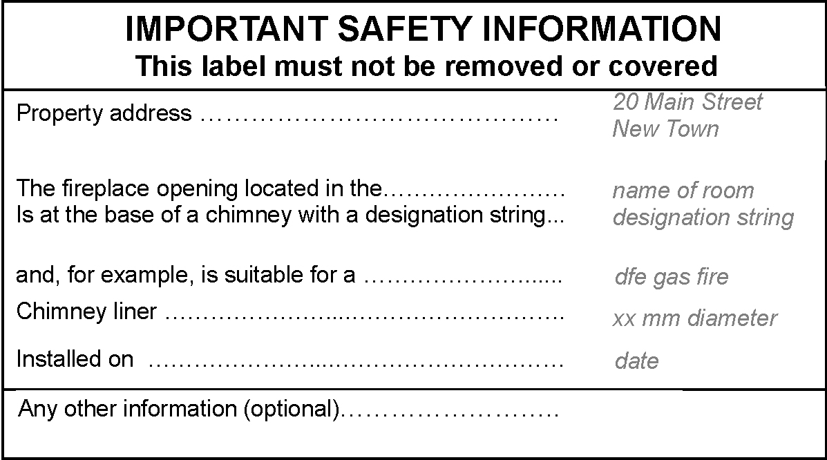
3.17.8 Extract fans
Extract fans lower the pressure in a building and may cause the spillage of combustion products from open-flued appliances. This can occur even if the appliance and the fan are in different rooms. Ceiling fans produce currents and hence local depressurisation that can also cause the spillage of flue gases. The presence of some fans may be obvious, such as those on view in kitchens, but others may be less obvious. Fans installed in appliances such as tumble dryers or other open-flued combustion appliances can also contribute to depressurisation. Fans may also be provided to draw radon gas out of the underbuilding.
In buildings where it is intended to install open-flued combustion appliances and extract fans, the combustion appliances should be able to operate safely whether or not the fans are running.
The installation of extract fans should be in accordance with the guidance below, and should be tested to show that combustion appliances operate safely whether or not fans are running:
a.for solid fuel appliances, extract ventilation should not generally be installed in the same room or alternatively seek further guidance from HETAS. However in certain cases, such as large rooms where there is free flowing replacement air, a fan may be fitted provided a satisfactory spillage test is carried out in accordance with BRE Information Paper IP 7/94
b.for oil-firing appliances, limit fan capacities as described in OFTEC Technical Book 3 and then carry out flue draught interference tests as described in Book 3 or BS 5410: Part 1: 1997
c.for a gas-fired appliance, where a kitchen contains an open-flued appliance, the extract rate of the kitchen extract fan should not exceed 20 litres/second. To check for safe operation of the appliance(s) the recommendations in clause 5.3.2.3 of BS 5440: Part 1: 2000 should be followed.
3.18 Combustion appliances – protection from combustion products
#Source page 62
Mandatory Standard
| Standard 3.18 Every building must be designed and constructed in such a way that any component part of each fixed combustion appliance installation used for the removal of combustion gases will withstand heat generated as a result of its operation without any structural change that would impair the stability or performance of the installation. |
3.18.0 Introduction
The fire service attends many calls to chimney fires and other fires where a chimney defect has allowed fire spread into a building. Whilst the guidance in this sub-section cannot prevent fires, the structural precautions recommended help to limit the damage to flues and thus prevent fire from spreading.
It is essential that flues continue to function effectively when in use without allowing the products of combustion to enter the building. Chimneys and flue-pipes are now tested to harmonised European standards to establish their characteristics relative to safe operation.
Very low flue-gas temperatures are achieved by modern, high efficiency appliances, particularly during night conditions, thus causing condensation. Materials need to withstand these aggressive situations.
Explanation of terms
The following terms are included to provide clarity to their meaning in this Technical Handbook.
Chimney – a structure enclosing 1 or more flues, but not a flue-pipe, and including any openings for the accommodation of a combustion appliance, but does not include a chimney terminal
Custom-built chimney – chimney that is installed or built on site using a combination of compatible chimney components that may be from 1 or different sources
Double-walled chimney – chimney consisting of a flue liner and an outer wall
Factory-made chimney – see system chimneys
Flue – passage for conveying the products of combustion to the outside atmosphere
Flue-block – factory-made chimney components with 1 or more flues
Flue liner – wall of a chimney consisting of components the surface of which is in contact with products of combustion
Flue-pipe – (correctly termed ‘connecting flue-pipe’) a pipe that connects a combustion appliance to a flue in a chimney
Single-walled chimney – chimney where the flue liner is the chimney
System chimneys – (factory-made chimney) chimney that is installed using a combination of compatible chimney components, obtained or specified from one manufacturing source with product responsibility for the whole chimney.
Some of these terms are explained in greater depth later in the guidance to this standard.
Conversions - in the case of conversions, as specified in regulation 4, the building as converted shall meet the requirement of this standard (regulation 12, schedule 6).
3.18.1 Chimneys generally
Combustion appliances are very often changed after the original installation. Unless an appliance is supplied to be used with a specified system chimney or with an integral duct assembly, e.g. balanced flue, it is desirable, and sometimes more economical, to cater initially for the most severe conditions as regards the danger of fire, generally a traditional open fire, and to ensure that all components are compatible.
Combustion appliances, other than flue-less appliances such as gas cookers, should incorporate, or be connected to, a flue-pipe and/or a chimney that will withstand the heat generated by the normal operation of the appliance. A chimney of a higher specification than the designation strings given (see clause 3.18.2) may be used if required, such as a chimney generally suitable for use with an open-flued solid fuel appliance may be used with an open flued gas-fired appliance.
The National Association of Chimney Engineers (NACE) http://www.nace.org.uk/ was set up to ensure the safety of all fuel users who depend upon a chimney or flue for the operation of a heating appliance. They provide a register of competent and qualified chimney engineers for all types of chimney work. Advice is also available from the British Flue and Chimney Manufacturers’ Association (BFCMA) http://www.feta.co.uk/. These organisations do not have a mandatory status.
Sweeping chimneys - the process of burning will naturally cause deposits of soot in the flue. Chimneys and flue-pipes therefore should be swept at least annually if smokeless solid fuel is burnt and more often if wood, peat and/or other high volatile solid fuel such as bituminous coal is burnt. Mechanical sweeping with a brush is the recommended method of cleaning.
Every chimney should have such capacity, be of a height and location and with an outlet so located that the products of combustion are discharged freely and will not present a fire hazard.
A flue should be free from obstructions. The surface of the flue should be essentially uniform, gas-tight and resistant to corrosion from combustion products. Chimneys should be constructed in accordance with:
a.the recommendations of BS 6461: Part 1: 1984 for masonry chimneys, or
b.the recommendations of BS 7566: Parts 1 - 4: 1002 for metal system chimneys, or
c.BS 5410: Part 1: 1997 and OFTEC Technical Book 3, where serving an oil-firing appliance, or
d.BS 5440: Part 1: 2000, where serving a gas-fired appliance.
3.18.2 Chimney designations
Designations for chimneys, according to BS EN 1443: 2003, are dependant on the fuel to be used, the type of appliance and the operating conditions. The designation string prescribes limiting values or categories for temperature, pressure, condensate resistance, corrosion resistance, soot fire resistance and distance to combustibles. Values for which the chimneys is suitable are specified by the system chimney manufacturer or the designer of a custom built or re-lined chimney. For a new chimney installation the chimney designation should be chosen to suit the intended appliance installation. For an existing chimney the appliance performance should be chosen to match the designation of the chimney. Advice on the appropriate chimney specification should be sought from the appliance manufacturer.
The recommended designation for chimneys and flue-pipes for use with natural draught, solid fuel appliances is T400 N2 D 3 Gxx.
The recommended designation for chimneys and flue-pipes for use with forced draught solid fuel appliances that have a positive pressure at the outlet of the appliance is T400 P2 D 3 Gxx.
The pressure designation P2 is regarded as the default specification. However the chimney can often generate an adequate natural draught, so that the appliance can be safely used with chimneys and flue-pipes with the negative pressure designation even if the appliance is fanned. The draught generated in a chimney may be calculated according to BS EN 13384-1: 2002. If there is any doubt, and/or unless the appliance manufacturer specifies N2, the designation P2 should apply.
Table 3.10. Recommended designation for chimneys and flue-pipes for use with oil-firing appliances with a flue gas temperature not more than 250ºC
| Appliance type | Fuel oil | Designation |
|---|---|---|
| Boiler including combustion boiler - pressure jet | Class C2 | T250 N2 D 1 Oxx |
| Cooker - pressure jet burner | Class C2 | T250 N2 D 1 Oxx |
| Cooker and room heater - vaporising burner | Class C2 | T250 N2 D 1 Oxx |
| Cooker and room heater - vaporising burner | Class D | T250 N2 D 2 Oxx |
| Condensing pressure jet burner appliances | Class C2 | T160 N2 W 1 Oxx |
| Cooker - vapourising burner appliances | Class D | T160 N2 W 2 Oxx |
Additional information:
The pressure designation N2 is regarded as the most likely specification to apply in the oil industry for both vaporising and pressure jet appliances. Most pressure jet appliances only generate adequate pressure to overcome flow resistance within the appliance so that the products of combustion entering the chimney will be at a negative pressure with respect to the atmosphere. Thus the appliance can be safely used with chimneys and flue-pipes with negative pressure designation. In the event that an appliance design produces a positive pressure at the outlet of the appliance, it is the manufacturer’s responsibility to inform the installer that a chimney with a positive designation should be used. If there is any doubt, the more onerous designation P2 should apply.
The appliance manufacturer’s instructions should always be checked. They may specify a higher designation.
Table 3.11. Recommended designation for chimneys and flue-pipes for use with gas appliances
| Appliance | Type | Designation |
|---|---|---|
| Boiler - open - flued | T250 N2 D 1 Oxx T250 P2 D 1 Oxx[1] T250 P2 W 1 Oxx[1] | |
| Boiler - room - sealed | T250 N2 D 1 Oxx T250 P2 D 1 Oxx[1] | |
| Gas fire | T250 N2 D 1 Oxx | |
| Air heater | T250 N2 D 1 Oxx T250 P2 D 1 Oxx[1] T450 N2 D 1 Oxx |
Additional information:
The pressure designation P2 is regarded as the default specification. However the chimney can often generate an adequate natural draught, so that the appliance can be safely used with chimneys and flue-pipes with the negative pressure designation even for many fanned draught gas appliances, including condensing boilers that may otherwise have positive pressure at the outlet to the flue. The draught generated in a chimney may be calculated according to BS EN 13384-1: 2002. If there is any doubt, and/or unless the appliance manufacturer specifies N2, the designation P2 should apply.
3.18.3 Masonry chimneys
A new masonry chimney, usually custom-built on site, and normally with an outer wall of brick, block or stone, should be well constructed and incorporate a flue liner, or flue-blocks, of either clay material or precast concrete. A masonry chimney should be constructed in accordance with the recommendations in BS 6461: Part 1: 1984. If an outer wall is constructed of concrete it should be constructed in accordance with BS EN 12446: 2003.
It is a complex operation to upgrade the chimney at a later date to serve a new appliance that needs a higher classification of chimney to operate safely, thus a chimney designed for solid fuel will also serve for oil or gas. See clause 3.18.6 for guidance on flue liners.
Chimneys can also be constructed of prefabricated block components, designed for quick construction. Chimney components such as cappings, offsets and precast fireplace components are available with this type of system. Some flue-blocks are specially designed for gas-fired appliances only. Flue-blocks should be constructed and installed in accordance with recommendations in:
a.BS EN 1858: 2003, for a precast concrete flue-block chimney
b.BS EN 1806: 2006, for a clay flue-block chimney.
3.18.4 Metal chimneys
Metal chimneys may be either single-walled or double-walled. Each of these types is commonly factory-made by one manufacturer as sets of components for easy assembly on site (although they can be supplied as 1 unit) and is thus a system chimney. A choice of fittings such as bends, brackets, and terminals are available.
Some metal chimneys are specifically designed for use with gas-fired appliances and should not be used for solid fuel appliances because of the higher temperatures and greater corrosion risk.
Metal system chimneys, with the following designations, should be constructed in accordance with the recommendations in BS EN 1856-1: 2003:
a.T400 N1 D V3 (or Vm - Lxxxxx) Gxx, for solid fuel appliances
b.T400 P2 D V3 (or Vm - Lxxxxx) Gxx where it serves an oil-firing appliance producing a flue gas temperature of not more than 400ºC, e.g. burning Class D oil (gas oil)
c.T250 N2 D V2 (or Vm - Lxxxxx) Oxx where it serves an oil-firing appliance producing a flue gas temperature of not more than 250ºC, e.g. burning Class C2 oil (kerosene)
d.T250 N2 D V1 (or Vm - Lxxxxx) Oxx where it serves a gas appliance.
The corrosion resistance may be specified, according to BS EN 1856-1: 2003 by:
a.a corrosion test method, which leads to a value of either V1, V2 or V3, or
b.by a material specification code Vm - Lxxxxx where the first 2 digits represent a material type as quoted in BS EN 1856-1: 2003, Table 4 and the last 3 digits represent the material thickness.
Acceptable material specifications may be taken from the national Annex to BS EN 1856-1: 2003. For example, an acceptable material code for solid fuel, oil or gas, would be Vm - L50040 representing a material type 50 with a thickness of 0.40mm.
A metal chimney should not pass through a compartment wall, compartment floor, separating wall or separating floor. However they may if the chimney, or a non-combustible casing totally enclosing the chimney, is constructed in such a way that, in the event of a fire, the fire resistance of the compartment wall, compartment floor, separating wall or separating floor is maintained (see Section 2, Fire).
A metal chimney should only pass through a storage space, cupboard or roof space provided any flammable material is shielded from the chimney by a removable, imperforate casing. Also where the chimney passes through the roof space, such as an attic, it should be surrounded be a rigid mesh that will prevent vermin from building a nest beside the warm chimney. Mesh should prevent an 8mm diameter sphere from passing.
There should be no joints within any wall, floor or ceiling that make accessing the chimney for maintenance purposes difficult.
3.18.5 Flue-pipes
A flue-pipe should be of a material that will safely discharge the products of combustion into the flue under all conditions that will be encountered. A flue-pipe serving a solid fuel appliance should be non-combustible and of a material and construction capable of withstanding the effects of a chimney fire without any structural change that would impair the stability and performance of the flue-pipe.
Flue-pipes should be manufactured from the materials noted below:
a.cast iron pipe to BS 41: 1973 (1988)
b.mild steel at least 3mm thick, to Section 1.1 of BS 1449: Part 1: 1991
c.vitreous enamelled steel to BS 6999: 1989
d.stainless steel designated Vm - L50100, in accordance with BS EN 1856-2: 2005 or Vm - Lxxxxx for oil or gas applications
e.any other material approved and tested under the relevant conditions of a notified body.
Flue-pipes should have the same diameter or equivalent cross sectional area as that of the appliance flue outlet and should be to the size recommended by the appliance manufacturer. It should be noted that oversized flue-pipes can cause condensation problems in modern, highly efficient oil and gas fired boilers.
A flue-pipe connecting a solid fuel appliance to a chimney should not pass through:
a.a roof space
b.an internal wall, although it is acceptable to discharge a flue-pipe into a flue in a chimney formed wholly or partly by a non-combustible wall
c.a ceiling or floor. However it is acceptable for a flue-pipe to pass through a ceiling or floor where they are non-combustible and the flue-pipe discharges into a chimney immediately above.
3.18.6 Flue liners
A flue liner is the wall of the chimney that is in contact with the products of combustion. It can generally be of concrete, clay, metal or plastic depending on the designation of the application.
All new chimneys will have flue liners installed and there are several types, as follows:
•rigid sections of clay or refactory liner
•rigid sections of concrete liner
•rigid metal pipes.
Flue liners suitable for solid fuel appliances, and therefore generally suitable for other fuels, should have a performance at least equal to that corresponding to the designation T400 N2 D 3 G as described in BS EN 1443: 2003 and manufactured from the following materials:
a.clay flue liners with rebates or sockets for jointing and meeting the requirements for Class A1 N2 or Class A1 N1 as described in BS EN 1457: 1999, or
b.concrete flue liners meeting the requirements for the classification Type A1, Type A2, Type B1 or Type B2 as described in BS EN 1857: 2003, or
c.any other material approved and tested under the relevant conditions of a notified body.
Stainless steel flexible flue liners meeting BS EN 1856-2: 2005 may be used for lining or relining flues for oil and gas appliances, and for lining flues for solid fuel applications provided that the designation is in accordance with the intended application. These should be installed in accordance with their manufacturer’s instructions.
Single skin, stainless steel flexible flue liners may be used for lining flues for gas and oil appliances. These should be installed in accordance with their manufacturer’s instructions.
Double skin, stainless steel flexible flue liners for multi-fuel use should be installed in accordance with their manufacturer’s instructions.
Existing custom-built masonry chimneys may be lined or re-lined by one of the following flue liners:
•flexible, continuous length, single-skin stainless steel for lining or re-lining chimney flues for C2 oil and gas installations designated T250
•flexible, continuous length, double-skin stainless steel for lining or re-lining systems designated T400 for multi-fuel installations
•insulating concrete pumped in around an inflatable former
•spray-on or brush-on coating by specialist.
Existing chimneys for solid fuel applications may also be relined using approved rigid metal liners or single-walled chimney products, an approved cast-insitu technique or an approved spray-on or brush-on coating. Approved products are listed in the HETAS Guide.
Masonry liners for use in existing chimneys should be installed in accordance with their manufacturer’s instructions. Appropriate components should be selected to form the flue without cutting and to keep joints to a minimum. Bends and offsets should only be formed with factory-made components. Liners should be placed with the sockets or rebate ends uppermost to contain moisture and other condensates in the flue. In the absence of specific liner manufacturer’s instructions to the contrary, the space between the lining and the surrounding masonry could be filled with a weak insulating concrete.
The corrosion resistance of a metal liner may be specified, according to BS EN 1856-1: 2003 by either:
a.a corrosion test method, which leads to a value of either V1, V2 or V3, or
b.by a material specification code Vm - Lxxxxx where the first 2 digits represent a material type as quoted in BS EN 1856-1: 2003, Table 4 and the last 3 digits represent the material thickness.
Acceptable material specifications may be taken from the national Annex to BS EN 1856-1: 2003. For example, an acceptable material code for solid fuel, oil or gas, would be Vm - L50040 representing a material type 50 with a thickness of 0.40mm.
3.19 Combustion appliances – relationship to combustible materials
#Source page 63
Mandatory Standard
| Standard 3.19 Every building must be designed and constructed in such a way that any component part of each fixed combustion appliance installation will not cause damage to the building in which it is installed by radiated, convected or conducted heat or from hot embers expelled from the appliance. |
3.19.0 Introduction
Combustion appliances and their component parts, particularly solid fuel appliance installations, generate or dissipate considerable temperatures. Certain precautions need to be taken to ensure that any high temperatures are not sufficient to cause a risk to people and the building. The characteristics of solid fuel and some older style oil-firing appliances are more onerous than modern oil and gas-fired appliances.
Conversions - in the case of conversions, as specified in regulation 4, the building as converted shall meet the requirements of this standard in so far as is reasonably practicable, and in no case be worse than before the conversion (regulation 12, schedule 6).
3.19.1 Relationship of masonry chimneys to combustible material
Combustible material should not be located where the heat dissipating through the walls of fireplaces or flues could ignite it. All combustible materials therefore should be located at least 200mm from the surface surrounding a flue in a masonry chimney. However some combustible materials will not be a risk and do not need a 200mm separation distance nor do the flue gasses generated from some appliances reach a sufficiently high temperature to require it. The following materials may be located closer than 200mm to the surface surrounding a flue in a chimney:
•a damp proof course(s) firmly bedded in mortar
•small combustible fixings may be located not less than 150mm from the surface of the flue
•flooring, strapping, sarking, or similar combustible material may be located on the outer face of a masonry chimney.
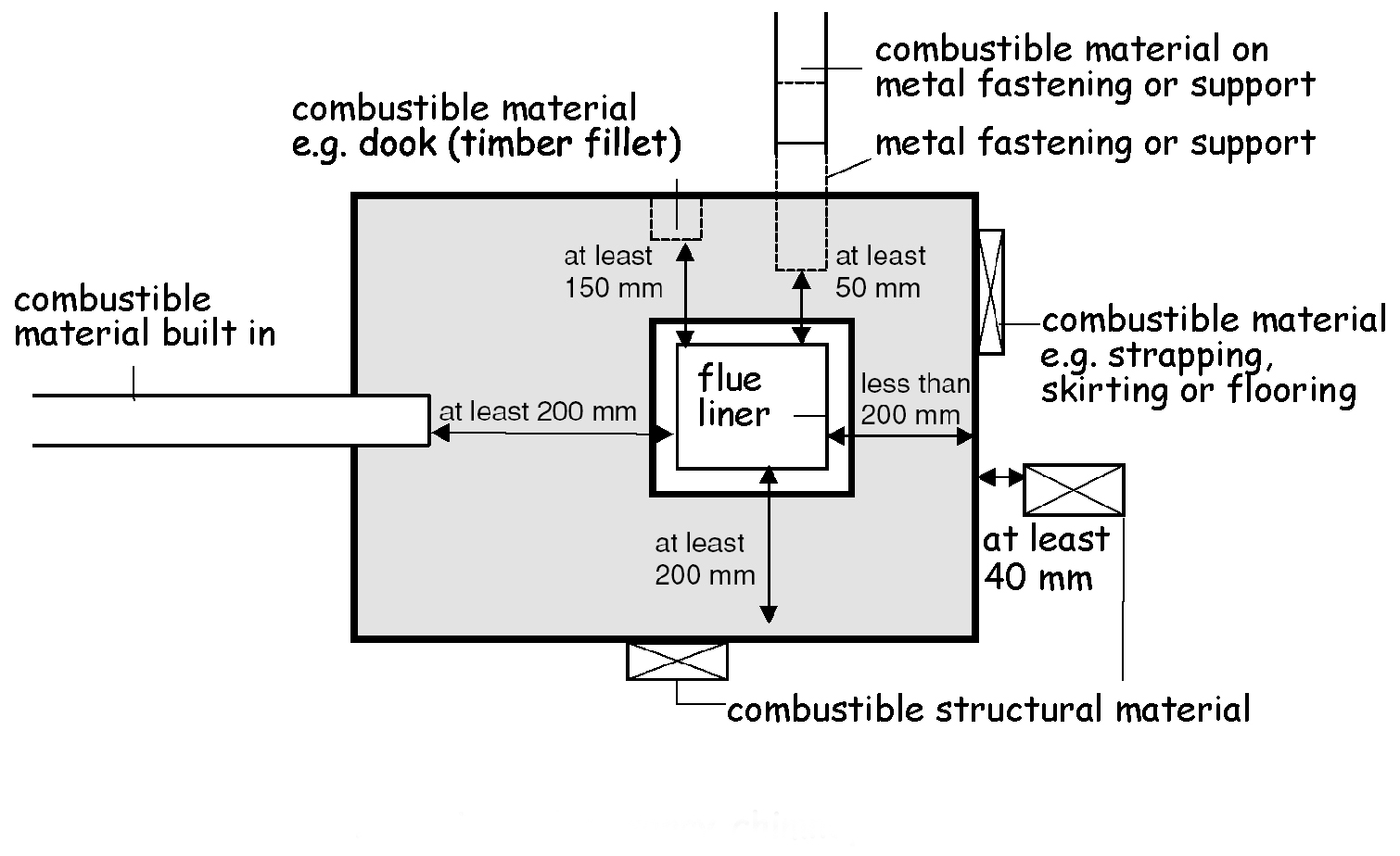
Any metal fastening in contact with combustible material, such as a joist hanger, should be at least 50mm from the surface surrounding a flue to avoid the possibility of the combustible material catching fire due to conduction.
BS EN 1806: 2006 relates to clay flue-block chimneys but does not give a value for distances to combustible materials. These types of chimneys therefore should be regarded as custom built chimneys and the minimum values in this clause 3.19.1 or clause 3.19.2 should be used and declared.
3.19.2 Relationship of system chimneys to combustible material
System chimneys do not necessarily require to be located at such a distance from combustible material. It is the responsibility of the chimney manufacturer to declare a distance ‘XX’, as stipulated in BS EN 1856-1: 2003 and BS EN 1858: 2003 as being a safe distance from the chimney to combustible material. At this distance, the temperature of adjacent combustible materials during operation of the appliance at its rated output should not exceed 85ºC when related to an ambient temperature of 20ºC.
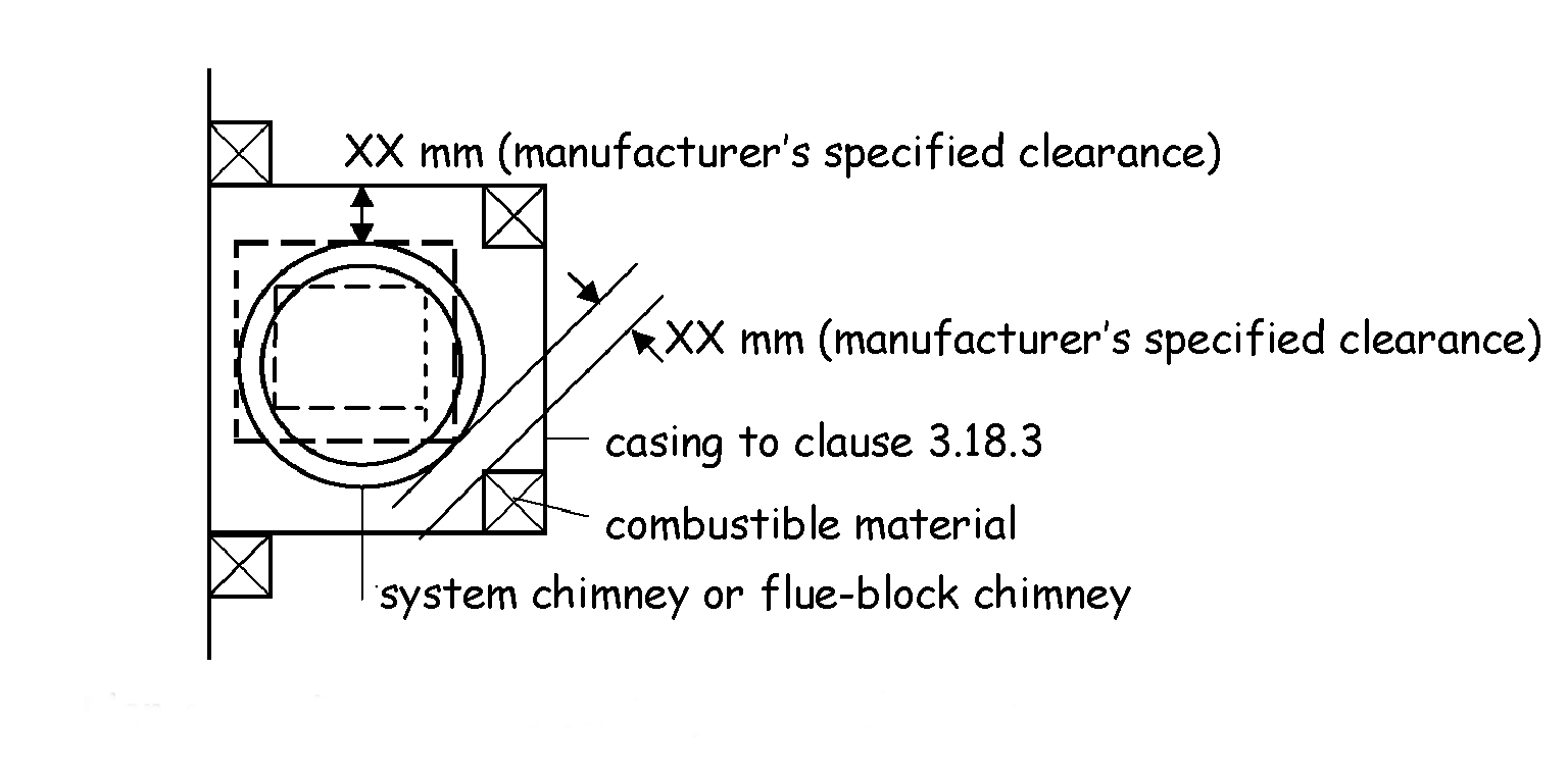
BS EN 1806: 2006 relates to clay flue-block chimneys but does not give a value for distances to combustible materials. These types of chimney therefore should be regarded as a custom built chimney and the minimum values in this clause 3.19.1 or clause 3.19.2 should be used and declared.
3.19.3 Relationship of metal chimneys to combustible material
There should be a separation distance where a metal chimney passes through combustible material. This is specified, as part of the designation string for a System chimneys when used for oil or gas, as (Gxx), where xx is the distance in mm. Where no data is available, the separation distance for oil or gas applications with a flue gas temperature limit of T250 or less should be 25mm from the outer surface of a single-walled chimney to combustible material. The 25mm should be measured from the surface of the inner wall of a double-walled chimney. There is no need for a separation distance if the flue gases are not likely to exceed 100ºC.
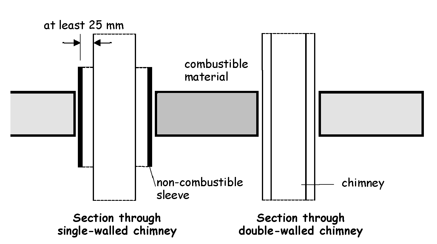
There should also be a separation distance where the metal chimney runs in close proximity to combustible material. The separation distance should be 25mm from the outer surface of a single-walled chimney to combustible material. The 25mm should be measured from the surface of the inner wall of a double-walled chimney. There is no need for a separation distance if the flue gases are not likely to exceed 100ºC.
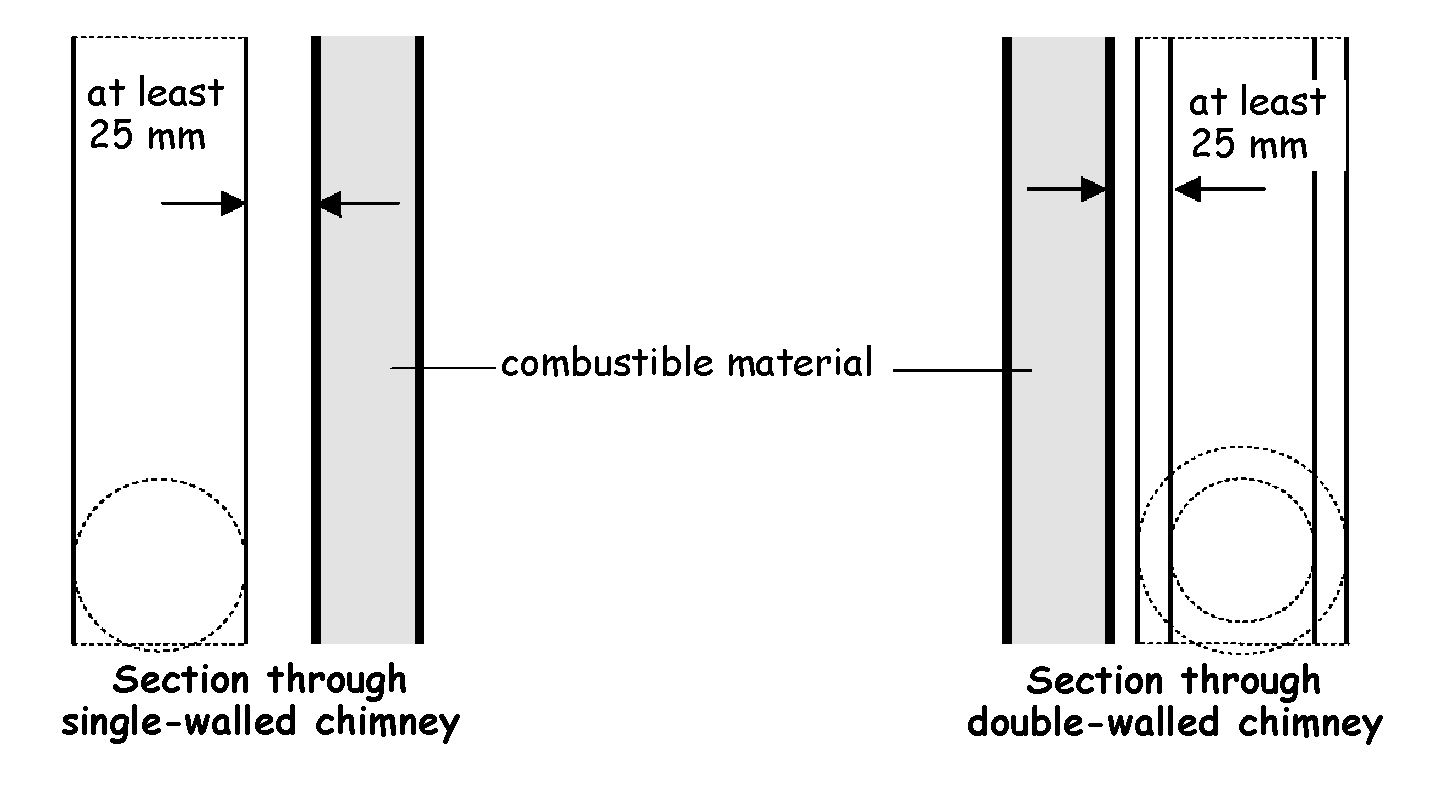
3.19.4 Relationship of flue-pipes to combustible material
To prevent the possibility of radiated heat starting a fire, a flue-pipe should be separated from combustible material by:
a.a distance according to the designation of the flue-pipe in accordance with BS EN 1856-2: 2005, or
b.a distance equivalent to at least 3 times the diameter of the flue-pipe. However this distance may be reduced:
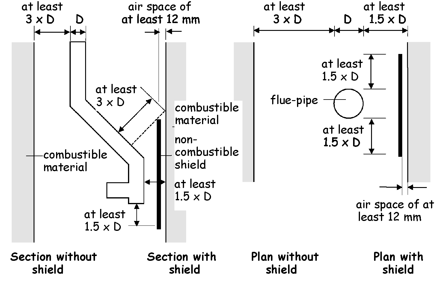
3.19.5 Relationship of solid fuel appliance to combustible material
A solid fuel appliance should be provided with a solid,non-combustible hearth that will prevent the heat of the appliance from igniting combustible materials. A hearth should be provided to the following dimensions:
a.a constructional hearth at least 125mm thick and with plan dimensions in accordance with the following sketches or
b.a free-standing, solid, non-combustible hearth at least 840 x 840mm minimum plan area and at least 12mm thick, provided the appliance will not cause the temperature of the top surface of the hearth on which it stands to be more than 100ºC.
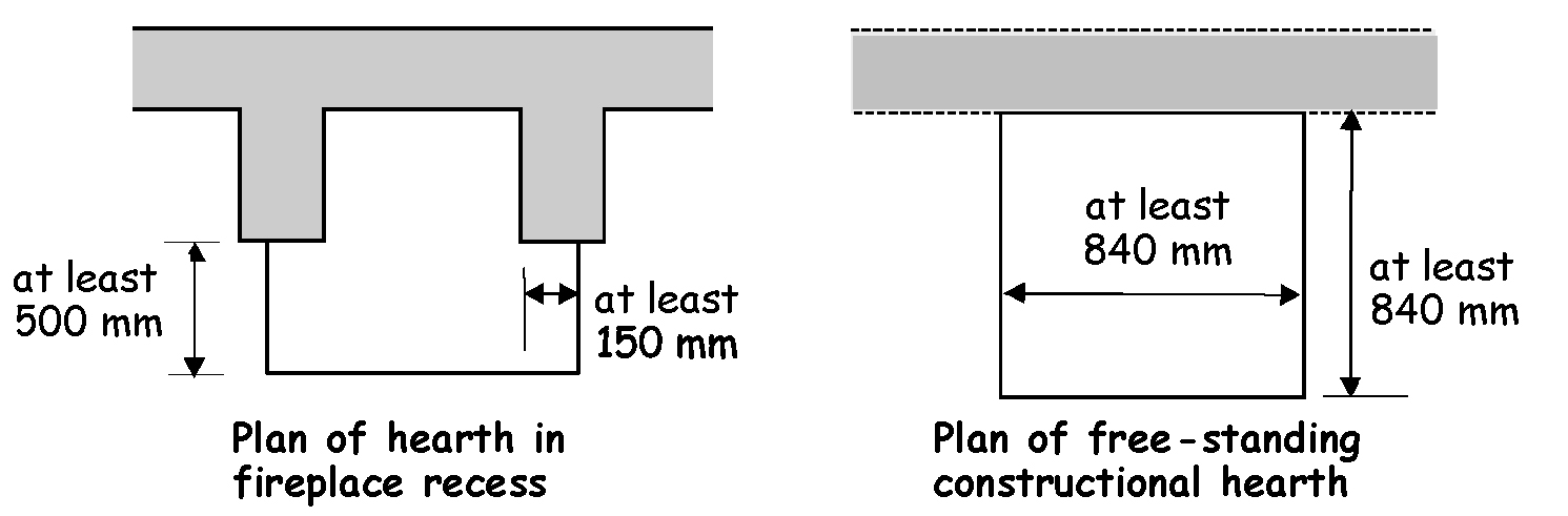
Not only should a solid fuel appliance sit on a hearth, but the appliance itself should also be located on the hearth such that protection will be offered from the risk of ignition of the floor by direct radiation, conduction or falling embers. The solid fuel appliance should be located on a hearth in accordance with the following diagram:
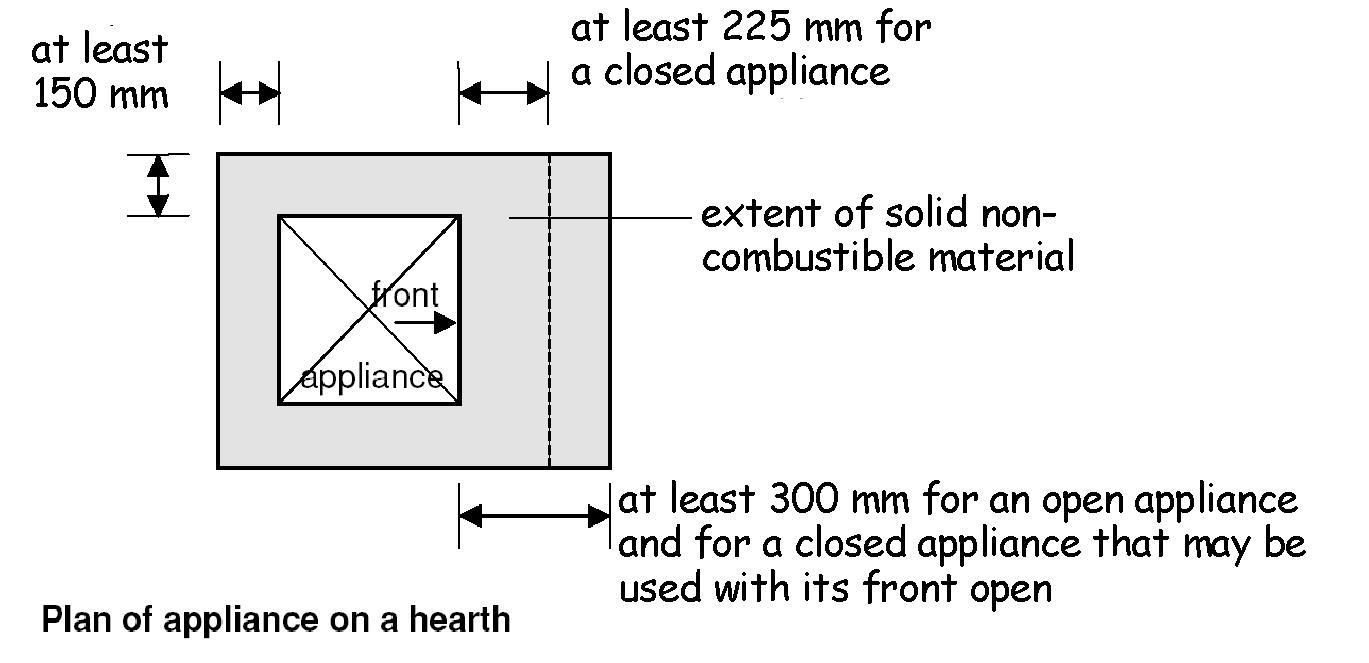
The 150mm does not apply where the appliance is located in a fireplace recess, nor does it apply where the back or sides of the hearth either abut or are carried into a solid, non-combustible wall complying with clause 3.19.8.
A solid fuel appliance may sit on a superimposed hearth provided the hearth is positioned partly or wholly on a constructional hearth. The superimposed hearth should be of solid, non-combustible material, usually decorative, and be at least 50mm thick in accordance with the following diagram:
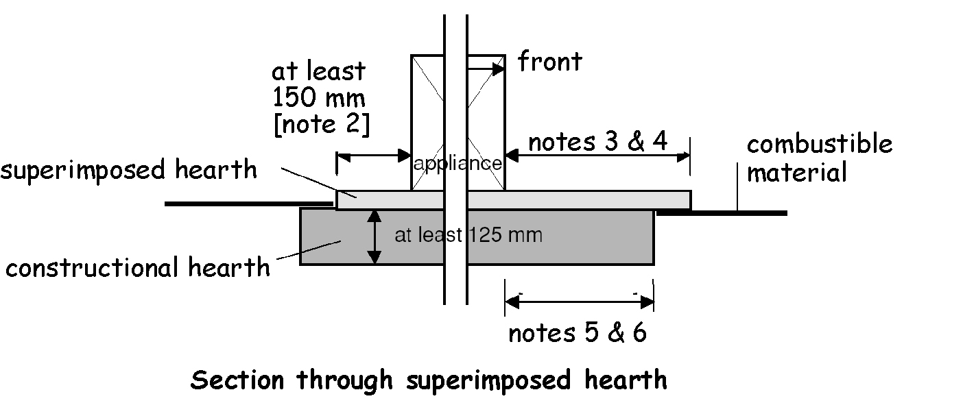
Additional information:
1.SUPERIMPOSED HEARTH means a finish of solid, non-combustible material, usually decorative, at least 50mm thick and positioned on a constructional hearth.
2.There need not be a 150mm separation where the appliance is located in a fireplace recess, nor where the back or sides of the hearth either abut or are carried into a solid, non-combustible wall complying with clause 3.14.8.
3.At least 225mm for a closed appliance.
4.At least 300mm for an open appliance and for a closed appliance that may properly be used with its front open.
5.No part of the appliance should project over any edge of the constructional hearth.
6.At least 150mm to combustible material measured horizontally.
3.19.6 Relationship of oil-firing appliance to combustible material
A hearth is not required beneath an oil-firing appliance if it incorporates a full sized, rigid non-combustible base and does not raise the temperature of the floor beneath it to more than 100ºC under normal working conditions. The base may be provided separately from the appliance. In other cases the appliance should stand on a hearth constructed and installed in accordance with the guidance for a solid fuel appliance.
A floor-standing, oil-firing appliance should be positioned on the hearth in such away as to minimise the risk of ignition of any part of the floor by direct radiation or conduction. An oil-firing appliance should be located on a hearth in accordance with the following diagram:
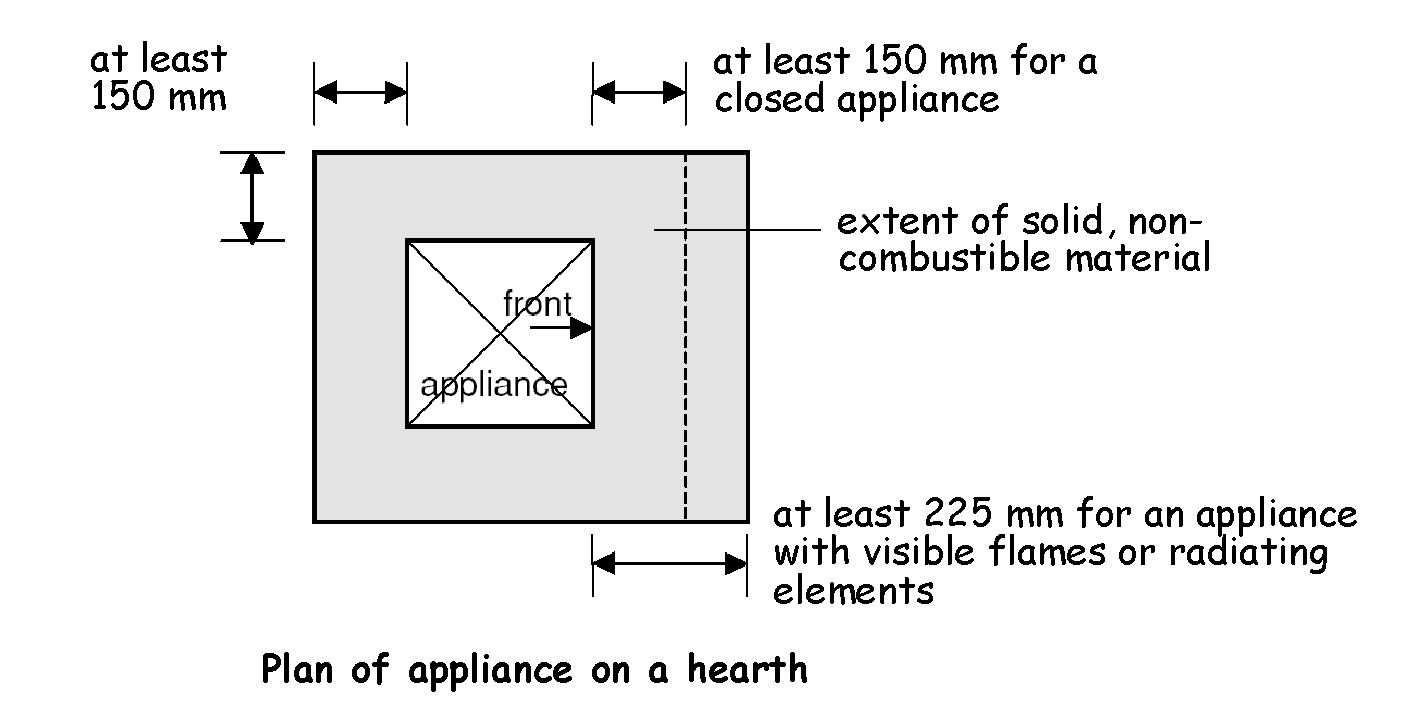
The 150mm does not apply where the appliance is located in a fireplace recess, nor does it apply where the back or sides of the hearth either abut or are carried into a solid, non-combustible wall complying with clause 3.19.8.
An oil-firing appliance should be separated from any combustible material if the temperature of the back, sides or top of the appliance is more than 100ºC under normal working conditions. Separation may be by:
a.a shield of non-combustible material at least 25mm thick, or
b.an air space of at least 75mm.
OFTEC Standard OFS A100 for boilers, OFS A101 for cookers and OFS A102 for room heaters defines suitable tests for measuring the temperature of the back, sides and top of an oil-firing appliance.
3.19.7 Relationship of gas-fired appliance to combustible material
A gas-fired appliance should be provided with a hearth in accordance with the following recommendations:
a.Clause 12 of BS 5871-1: 2005 for a gas fire, convector heater and fire/back boiler
b.Clause 12 of BS 5871-2: 2005 for an inset live fuel-effect gas appliance
c.Clause 11 of BS 5871-3: 2005 for a Decorative fuel-effect gas appliance
d.for any other gas-fired appliance, by a solid, heat resistant, non-combustible, non-friable material at least 12mm thick and at least the plan dimension shown in the diagram to this specification:
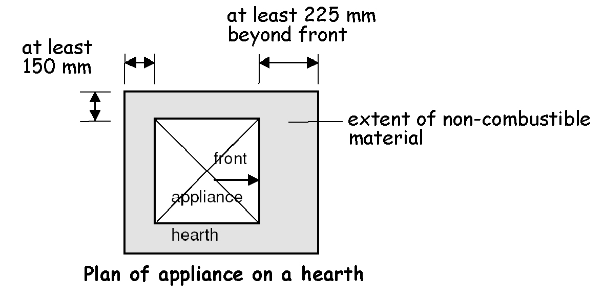
The 150mm does not apply where the appliance is located in a fireplace recess, nor does it apply where the back or sides of the hearth either abut or are carried into a solid, non-combustible wall complying with clause 3.19.8.
However a hearth need not be provided:
a.where every part of any flame or incandescent material in the appliance is at least 225mm above the floor, or
b.where the appliance is designed not to stand on a hearth, such as a wall mounted appliance or a gas cooker.
A gas-fired appliance should be separated from any combustible material if the temperature of the back, sides or top of the appliance is more than 100ºC under normal working conditions. Separation may be by:
1.a shield of non-combustible material at least 25mm thick, or
2.an air space of at least 75mm.
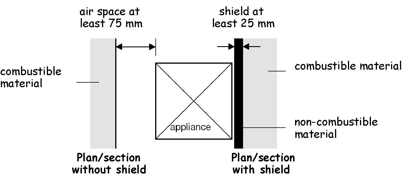
A gas-fired appliance with a CE marking and installed in accordance with the manufacturer’s written instructions may not require this separation.
3.19.8 Relationship of hearths to combustible material
Walls that are not part of a fireplace recess or a prefabricated appliance chamber but are adjacent to hearths or appliances should also protect the building from catching fire. This is particularly relevant to timber-framed buildings. Any part of a building therefore that abuts or is adjacent to a hearth, should be constructed in such a way as to minimise the risk of ignition by direct radiation or conduction from a solid fuel appliance located upon the hearth. This recommendation does not relate to floors, as an appliance should stand on a suitable hearth described in clauses 3.19.5, 3.19.6 and 3.19.7.
The building elements adjacent to combustion appliances should be constructed in accordance to the following recommendations:
a.the hearth located in a fireplace recess in accordance with BS 8303: Part 1: 1994, or
b.any part of the building, other than the floor, not more than 150mm from the hearth, constructed of solid, non-combustible material in accordance with the diagram and table to this specification:
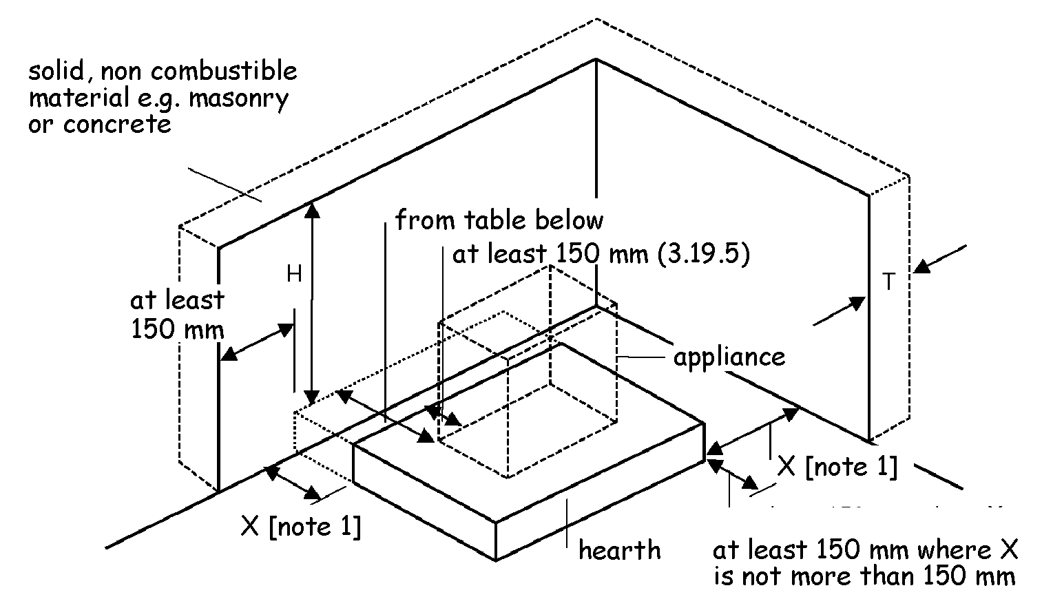
Table 3.12. Hearth and appliance adjacent to any part of a building
| Location of hearth or appliance | Thickness (T) of solid, non-combustible material | Height (H) of solid non - combustible material |
|---|---|---|
| Where the hearth abuts a wall and the appliance is not more than 50mm from the wall | 200mm | at least 300mm above the appliance or 1.2m above the hearth whichever is the greater. |
| Where the hearth abuts a wall and the appliance is more than 50mm but not more than 300mm from the wall | 75mm | at least 300mm above the appliance or 1.2m above the hearth whichever is the greater. |
| Where the hearth does not abut a wall and is not more than 150mm from the wall | 75mm | at least 1.2m above the hearth. |
Additional information:
1.There is no requirement for protection of the wall where X is more than 150mm.
All combustible material under a constructional hearth should be separated from the hearth by an air space of at least 50mm. However an air space is not necessary where:
a.the combustible material is separated from the top surface of the hearth by solid, non-combustible material of at least 250mm, or
b.the combustible material supports the front and side edges of the hearth.
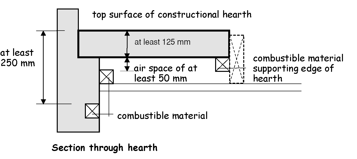
3.19.9 Fireplace recesses
A fireplace recess should be constructed of solid, non-combustible material in accordance with the recommendations in clauses 7 and 8 of BS 8303: Part 1: 1994 and to the minimum thickness shown in Figure 2 to BS 8303: Part 3: 1994. The recess should incorporate a constructional hearth.
An alternative is to use a prefabricated appliance chamber of solid concrete components. These components should be:
a.supplied by the same manufacturer, with pre-made jointing arrangements, assembled on site using a cement specified for the purpose by the manufacturer, and
b.of insulating concrete with a density of between 1200 and 1700 kg/m3, and
c.installed on a constructional hearth, and
d.of components having a minimum thickness shown in the table below:
Table 3.13. Thickness of solid fuel appliance chamber components
| Component | Minimum thickness (mm) |
|---|---|
| Base | 50 |
| Sides | 75 |
| Back panel and top slab | 100 |
| Hood and bar lintels | 100 |
3.20 Combustion appliances – removal of products of combustion
#Source page 64
Mandatory Standard
| Standard 3.20 Every building must be designed and constructed in such a way that the products of combustion are carried safely to the external air without harm to the health of any person through leakage, spillage, or exhaust nor permit the re-entry of dangerous gases from the combustion process of fuels into the building. |
3.20.0 Introduction
The guidance to this standard includes design and construction issues relating to chimneys and flues. In 2010-11 Fire fighters attended 1565 chimney fires in Scotland. The main cause of these fires was inadequate maintenance of the chimneys, including routine cleaning of flues.
Combustion appliances fuelled by solid fuel, oil or gas all have the potential to cause carbon monoxide (CO) poisoning if they are poorly installed or commissioned, inadequately maintained or incorrectly used. Inadequate ventilation or a lack of the correct maintenance of appliances, flues and chimneys are the main causes of CO poisoning. Poisonous CO gas is produced when fuel does not burn properly. Incidents of poisoning can also occur through deterioration of the structure of the flue or chimney. Every year in Scotland there are fatalities from CO poisoning directly attributed to combustion appliances installed in buildings. In addition to these deaths there are also a considerable number of incidents where people are treated in hospital for the effects of CO poisoning. In some cases CO poisoning can result in serious and permanent injury to persons affected. Where CO gas may occur within a building early detection and warning can play a vital role in the protection and safety of the occupants. This is particularly important in buildings with sleeping accommodation.
Incorrect sizing of flues can also have serious repercussions. If a flue is too small, an insufficient volume of air will pass through it and this may lead to spillage of combustion gases. Too large a flue will slow down the flow of combustion gases and this may also lead to spillage.
The use of fanned flues allows combustion appliances to be located away from external walls. In such installations the flues can often be concealed within ceiling or wall voids making it difficult to determine whether the flue is still in good condition when an appliance is serviced or maintained.
Damaged or poorly maintained flues can allow CO gases to escape from the flue before the intended termination point. Therefore flues passing through a building should be minimised. Where it is not possible to avoid a flue passing through the building the route of the flue should be carefully considered to minimise the risk to occupants.
Conversions - in the case of conversions, as specified in regulation 4, the building as converted shall meet the requirement of this standard (regulation 12, schedule 6).
3.20.1 Chimney and flue-pipe serving appliance burning any fuel
A chimney or flue-pipe serving any appliance should be suitable for use with the type of appliance served. A chimney should be manufactured using products in accordance with the following standards:
a.BS EN 1858: 2003, for concrete chimney blocks, or
b.BS EN 1806: 2000, for clay chimney blocks, or
c.BS EN 1457: 1999, for purpose made clay flue linings, or
d.BS EN 1856-1: 2003, for a factory-made metal chimney, or
e.a lining accepted for the purpose after testing of the chimney under the relevant conditions by a notified body.
3.20.2 Chimneys and flue-pipes serving solid fuel appliances
A flue in a chimney should be separated from every other flue and extend from the appliance to the top of the chimney. Every flue should be surrounded by non-combustible material that is capable of withstanding the effects of a chimney fire, without any structural change that would impair the stability or performance of the chimney. However the chimney may include a damp proof course (or courses) of combustible material.
3.20.3 Chimneys and flue-pipes serving oil-firing appliances
A chimney or flue-pipe serving an oil-firing appliance should be constructed to the recommendations of BS 5410: Part 1: 1997 or OFTEC Technical Book 3 and OFTEC Standard OFS E106 as appropriate.
Satisfactory specification of chimneys and flue-pipes depends upon the gas temperature to be expected in normal service. Flue gas temperatures depend upon appliance types and the age of their design. Older appliances are likely to produce flue gas temperatures greater than 250ºC while modern boilers that bear the CE mark indicating compliance with the Boiler (Efficiency) Regulations (1993) will normally have flue gas temperatures less than 250ºC. Information for individual appliances should be sought from manufacturer’s installation instructions, from the manufacturers themselves or from OFTEC. Where this is not available, flues should be constructed for an assumed flue gas temperature of more than 250ºC.
High flue gas temperatures - where the flue gas temperatures are more than 250ºC, under normal working conditions, custom-built chimneys, system chimneys and flue-pipes should be designed and constructed for use with a solid fuel appliance.
Low flue gas temperatures - where the flue gas temperatures are not more than 250ºC, under normal working conditions, chimneys and flue-pipes may be of a lower specification as follows:
a.in accordance with the guidance in clauses 3.18.3, 3.18.4, 3.18.5, relating to gas, and
b.where the oil-firing appliance burns Class D fuel, the inner surfaces of the chimney or flue-pipe should not be manufactured from aluminium.
The flue gas temperatures are quoted in manufacturer’s product data and can be measured in accordance with OFTEC Appliance Standard OFS A100 for boilers, OFS A101 for cookers or OFS A102 for room heaters.
3.20.4 Chimneys and flue-pipes serving gas-fired appliances
A chimney or flue-pipe should be constructed and installed in accordance with the following recommendations:
a.BS 5440-1: 2000
b.Section 8 of publication ‘IGE/UP/7 (Edition 2): ‘Gas Installation in timber framed and light steel framed buildings’, where the chimney or flue-pipe is in a timber frame building
c.the appropriate recommendations of the combustion appliance manufacturer, where the flue-pipe is supplied as an integral part of the combustion appliance.
3.20.5 Oil-firing appliances in bathrooms and bedrooms
There is an increased risk of carbon monoxide poisoning in bathrooms, shower rooms or rooms intended for use as sleeping accommodation, such as bed-sitters. Because of this, open-flued oil-firing appliances should not be installed in these rooms or any cupboard or compartment connecting directly with these rooms. Where locating a combustion appliance in such rooms cannot be avoided, the installation of a room-sealed appliance would be appropriate.
3.20.6 Gas-fired appliances in bathrooms and bedrooms
Regulation 30 of the Gas Safety (Installations & Use) Regulations 1998 has specific requirements for room-sealed appliances in these locations.
3.20.7 Protection of metal chimneys
Metal chimneys should be guarded if there could be a risk of damage or if they present a risk to people that is not immediately apparent such as when they traverse intermediate floors out of sight of the appliance.
Where the metal chimney passes through a room or accessible space such as a walk-in cupboard it should be protected in accordance with the recommendations of:
•BS EN 12391-1: 2004, for solid fuel appliances
•BS 5410: Part 1: 1997, for oil-firing appliances
•BS 5440: Part 1: 2000, for gas appliances.
It is not necessary to provide protection where a system chimney runs within the same space as the appliance served.
3.20.8 Size of flues – solid fuel appliances
The size of a flue serving a solid fuel appliance should be at least the size shown in the table below and not less than the size of the appliance flue outlet or that recommended by the appliance manufacturer.
Table 3.14. Thickness of solid fuel appliance chamber components
| Appliance | Minimum flue size [2] |
|---|---|
| Fireplace with an opening more than 500mm x 550mm, or a fireplace exposed on 2 or more sides | |
| Fireplace with an opening not more than 500mm x 550mm | 200mm diameter or rectangular/square flues having the same cross sectional area and a minimum dimension not less than 175mm |
| Closed appliance with rated output more than 30kW but not more than 50kW, burning any fuel | 175mm diameter or rectangular/square flues having the same cross sectional area and a minimum dimension not less than 150mm |
| Closed appliance with rated output not more than 30kW burning any fuel | 150mm diameter or rectangular/square flues having the same cross sectional area and a minimum dimension not less than 125mm |
| Closed appliance with rated output not more than 20kW that burns smokeless or low volatiles fuel | 125mm diameter or rectangular/square flues having the same cross sectional area and a minimum dimension not less than 100mm for straight flues or 125mm for flues with bends or offsets |
Additional information:
1.Closed appliance includes cookers, stoves, room heaters and boilers. Smokeless fuel means solid mineral fuel that produces combustion products containing particulate matter that does not exceed a specified low amount.
2.Any chimney pot or open-topped terminal must maintain the same cross-sectional area as the flue. Any covered terminal should have side outlets with a total free area twice that of the flue.
3.Specialist advice should be sought when proposing to construct flues with an area of more than 120000mm2 or 15% of the total face area of the fireplace opening.
4.Figure 3.49 should only be used for the range of sizes shown within the shaded area.
5.Fire size is related to the free opening area at the front of the fireplace opening.
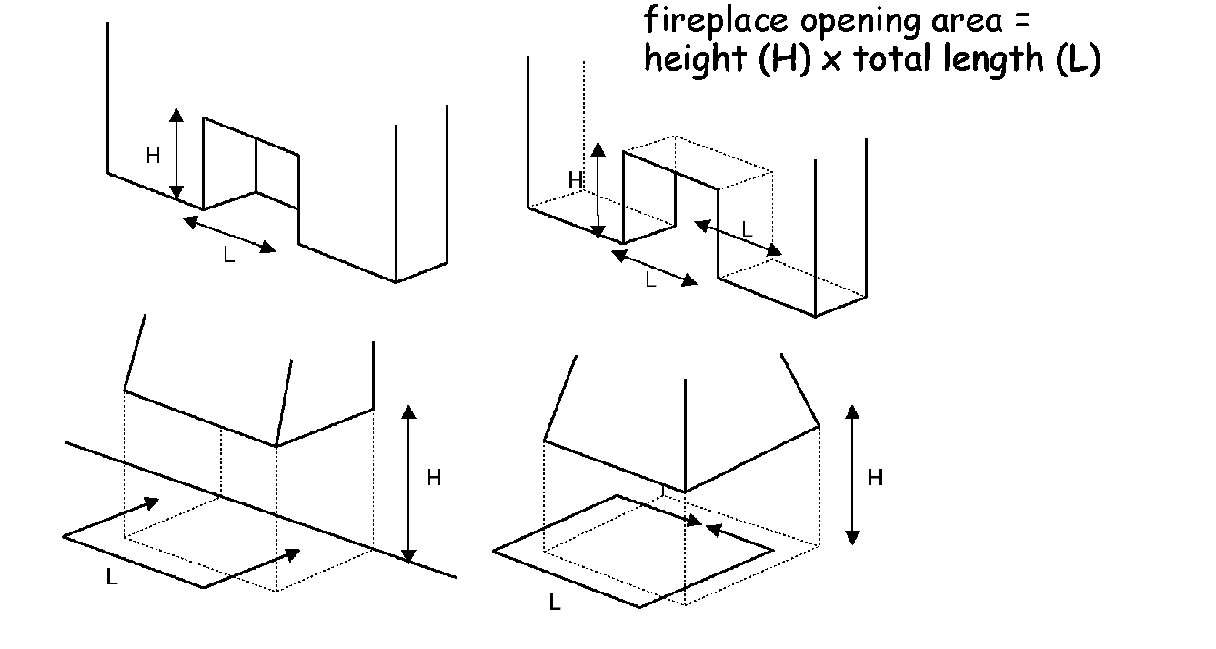
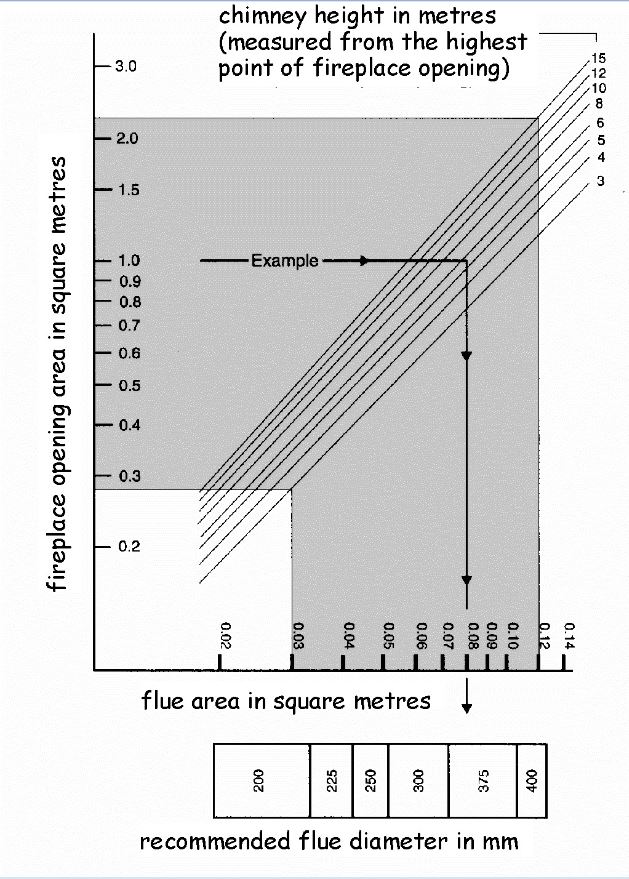
3.20.9 Size of flues – oil-firing appliances
The cross sectional area of a flue serving an oil-firing appliance should be in accordance with the recommendations in BS 5410: Part 1: 1997 and should be the same size as the appliance flue spigot.
3.20.10 Size of flues – gas-fired appliances
The area of a flue serving a gas-fired appliance should have a size to ensure safe operation. A flue should be provided in accordance with the following recommendations:
•Clause 9 of BS 5871-3: 2005, for a Decorative fuel-effect gas appliance
•BS 5871-2: 2005, for an inset live fuel-effect gas appliance
•BS 5440: Part 1: 2000, for any other gas-fired appliance.
3.20.11 Design of flues
A combustion appliance should be connected to a chimney that discharges to the external air. However there are some combustion appliances that are designed not to discharge direct to the external air, such as flueless cookers. An opening window, extract fan or passive stack ventilation system may be sufficient to ventilate a kitchen but where other types of flueless appliances are installed, the manufacturer’s instructions should be followed. Every solid fuel appliance should be connected to a separate flue.
Every oil-firing appliance should be connected to a separate flue. However this is not necessary where all the appliances have pressure jet burners and are connected into a shared flue.
Every gas-fired appliance that requires a flue should connect into a separate flue. However in certain instances, appliances can be connected to shared flues, if they are installed in accordance with the recommendations in BS 5440: Part 1: 2000.
The flue of a natural draught appliance, such as a traditional solid fuel appliance, should offer the least resistance to the passage of combustion gases. Resistance can be minimised by restricting the number of bends and horizontal runs should only be incorporated on back-entry appliances.
The horizontal length of the back-entry flue pipe at the point of discharge from the appliance should be not more than 150mm.
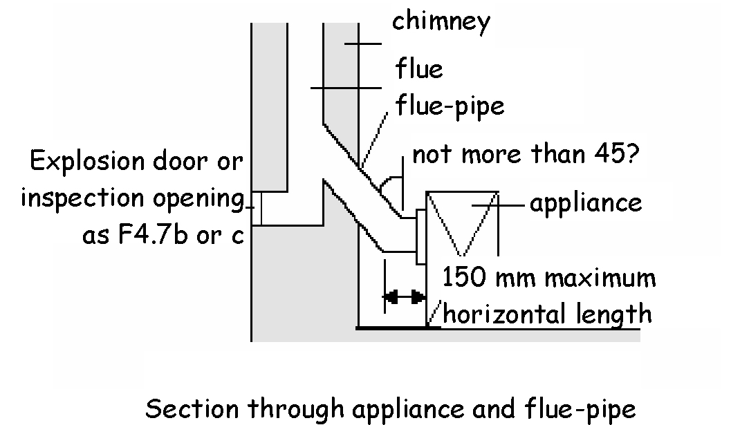
Where bends are essential, they should be angled at not more than 45º to the vertical.
3.20.12 Openings in flues
The flue should have no intermediate openings. However it is acceptable to provide a draught stabiliser or draft diverter on the chimney provided it is in the same room or space as the appliance being served. An explosion door may also be provided.
3.20.13 Access to flues
Access should be provided for inspection and cleaning of the flue and the appliance and therefore an opening that is fitted with a non-combustible, rigid, gas-tight cover would be acceptable.
Adequate provision for inspecting flues that are positioned within a void, for example a service duct or above a suspended ceiling, should be provided. Such provisions will allow essential safety checks to be made by engineers when a combustion appliance is worked on, both during initial commissioning and any subsequent servicing.
Access hatches should be 300mm x 300mm or larger where necessary to allow sufficient access to the void to look along the length of the flue. The number and position of access hatches should allow the entire length of the concealed flue to be inspected with at least one hatch located within 1.5m of any joint in the flue system.
Access hatches are intended for inspection purposes only, it is not intended that they allow full physical access to the flue system.
3.20.14 Location of metal chimneys
To minimise the possibility of condensation in a metal chimney, it should not be fixed externally to a building, but should be routed inside the building. However a metal chimney may be fixed externally if it is insulated and constructed of a material that can be used externally, such as stainless steel or, in the case of gas, aluminium, so long as they conform to the specifications of the National Annex to BS EN 1856-1: 2003.
3.20.15 Terminal discharges at low level
Combustion gasses at the point of discharge can be at a high temperature. Therefore flues discharging at low level where they may be within reach of people should be protected with a terminal guard.
A flue terminal should be protected with a guard if a person could come into contact with it or if it could be damaged. If the flue outlet is in a vulnerable position, such as where the flue discharges within reach of the ground, or a balcony, veranda or window, it should be designed to prevent the entry of matter that could obstruct the flow of gases.
3.20.16 Terminal discharge from condensing boilers
The condensate plume from a condensing boiler can cause damage to external surfaces of a building if the terminal location is not carefully considered. The manufacturer’s instructions should be followed.
3.20.17 Solid fuel appliance flue outlets
The outlet from a flue should be located externally at a safe distance from any opening, obstruction or flammable or vulnerable materials. The outlets should be located in accordance with the following diagram:
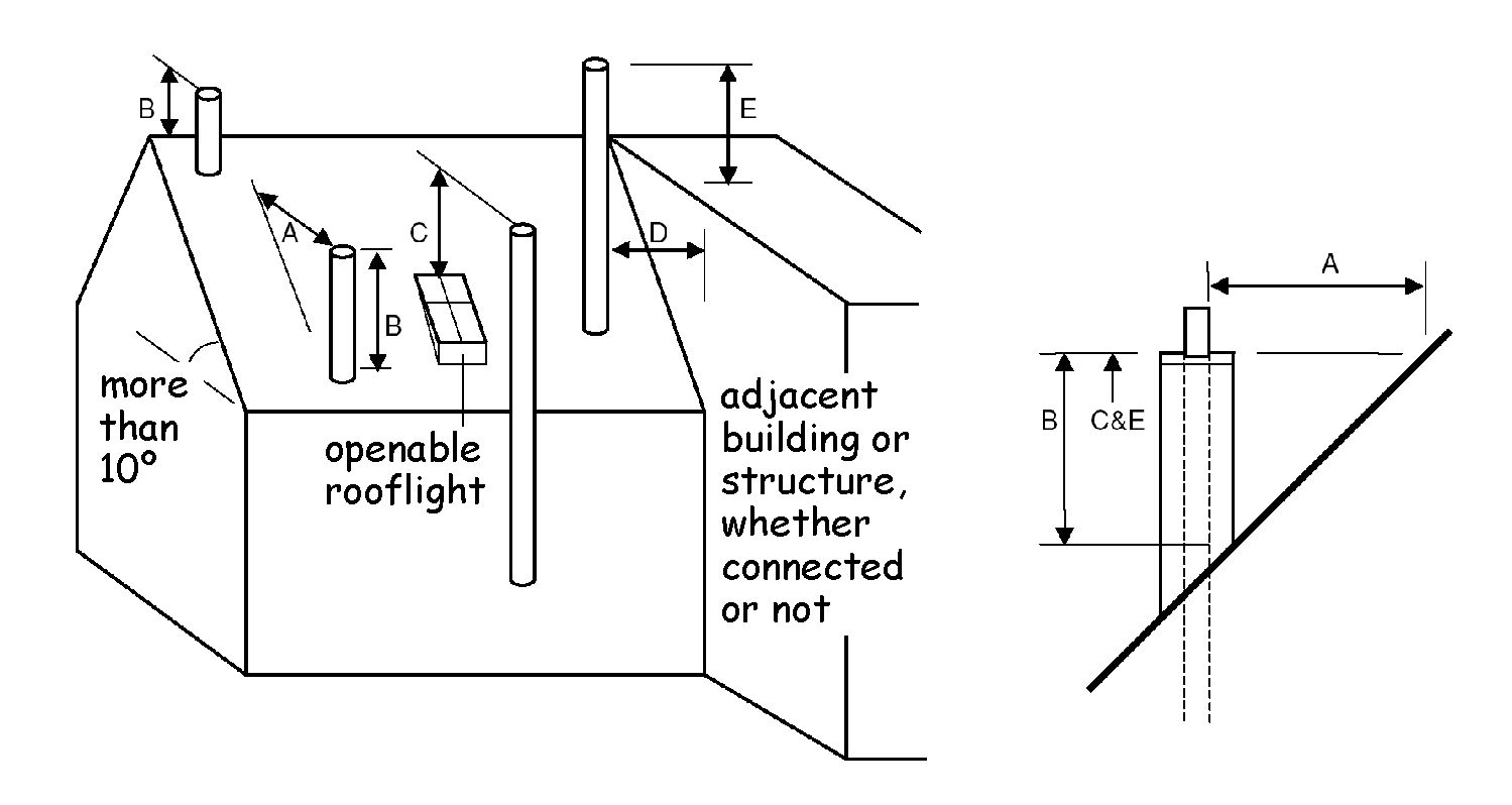
Table 3.15. Minimum dimension to flue outlets
| Location | Minimum dimension to flue outlets |
|---|---|
| A | 2300mm horizontally clear of the weather skin. |
| B | 1000mm provided A is satisfied; or 600mm where above the ridge. However, where the roof is thatch or shingles, the dimensions should be as diagram 2 to clause 3.20.17. |
| C | 1000mm above the top of any flat roof; and 1000mm above any openable rooflight, dormer or ventilator, etc. within 2300mm measured horizontally. |
| D/E | where D is not more than 2300mm, E must be at least 600mm. |
Additional information:
1.Horizontal dimensions are to the surface surrounding the flue.
2.Vertical dimensions are to the top of the chimney terminal.
Flue terminals in close proximity to roof coverings that are easily ignitable, such as thatch or shingles, should be located outside Zones A and B in the following diagram:
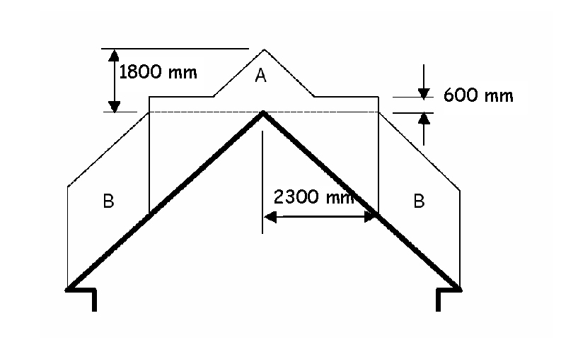
Table 3.16. Location of flue terminals relative to easily ignitable roof coverings
| Location | Location of flue terminals relative to easily ignitable roof coverings |
|---|---|
| Zone A | At least 1800mm vertically above the weather skin; and at least 600mm above the ridge. |
| Zone B | At least 1800mm vertically above the weather skin; and at least 2300mm horizontally from the weather skin. |
3.20.18 Oil-firing appliance flue outlets
The outlet from a flue should be located externally at a safe distance from any opening, obstruction or combustible material. The outlets should be located in accordance with the following diagram:
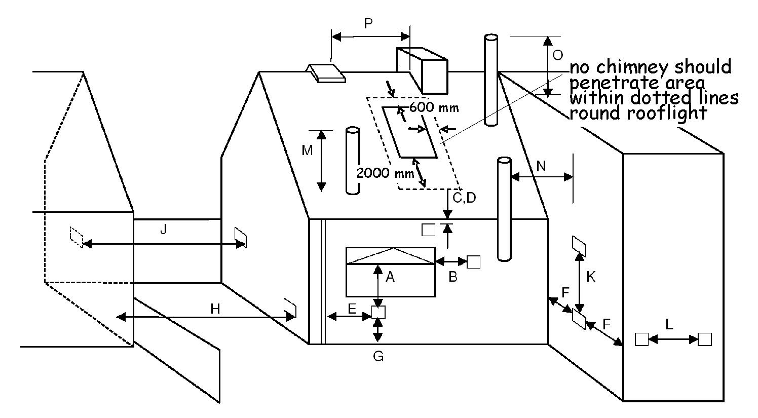
Table 3.17. Flue terminal positions for oil-firing appliances
| Location | Minimum distance to terminal (mm) | |
|---|---|---|
| pressure jet | vaporising | |
| A. Directly below an opening, air brick, opening window etc | 600 | not allowed |
| B. Horizontally to an opening, air brick, opening window etc | 600 | not allowed |
| C. Below a gutter, eaves or balcony with protection | 75 | not allowed |
| D. Below a gutter, eaves or balcony without protection | 600 | not allowed |
| E. From vertical sanitary pipework | 300 | not allowed |
| F. From an internal or external corner | 300 | not allowed |
| G. Above ground or balcony level | 300 | not allowed |
| H. From a surface or boundary facing the terminal | 600 [6] | not allowed |
| J. From a terminal facing the terminal | 1200 | not allowed |
| K. Vertically from a terminal on the same wall | 1500 | not allowed |
| L. Horizontally from a terminal on the same wall | 750 | not allowed |
| M. Above the highest point of an intersection with the roof | 600 [1] | 1000 [7] |
| N. From a vertical structure to the side of the terminal | 750 [1] | 2300 |
| O. Above a vertical structure not more than 750mm from the side of the terminal | 600 [1] | 1000 [7] |
| P. From a ridge terminal to a vertical structure on the roof | 1500 | not allowed |
Additional information:
1.Appliances burning Class D oil should discharge the flue gases at least 2m above ground level.
2.Terminating positions M, N, and O for vertical balanced flues should be in accordance with manufacturer’s instructions.
3.Vertical structure in N, O and P includes tank or lift rooms, parapets, dormers etc.
4.Terminating positions A to L should only be used for appliances that have been approved for low level flue discharge when tested in accordance with BS EN 303-1, OFS A100 or OFS A101.
5.Terminating positions should be at least 1800mm from an oil storage tank unless a wall with a non-combustible construction type 7, short duration (see table to 2.B.1) and more than 300mm higher and wider each side than the tank is provided between the tank and the terminating position.
6.Where a flue terminates not more than 600mm below a projection and the projection is plastic or has a combustible finish, then a heat shield of at least 750mm wide should be fitted.
7.The distance from an appliance terminal installed at right angles to a boundary may be reduced to 300mm in accordance with diagram 2 to clause 3.20.16.
8.Where a terminal is used with a vaporising burner, a horizontal distance of at least 2300mm should be provided between the terminal and the roof line.
9.Notwithstanding the dimensions above, a terminal should be at least 300mm from combustible material.
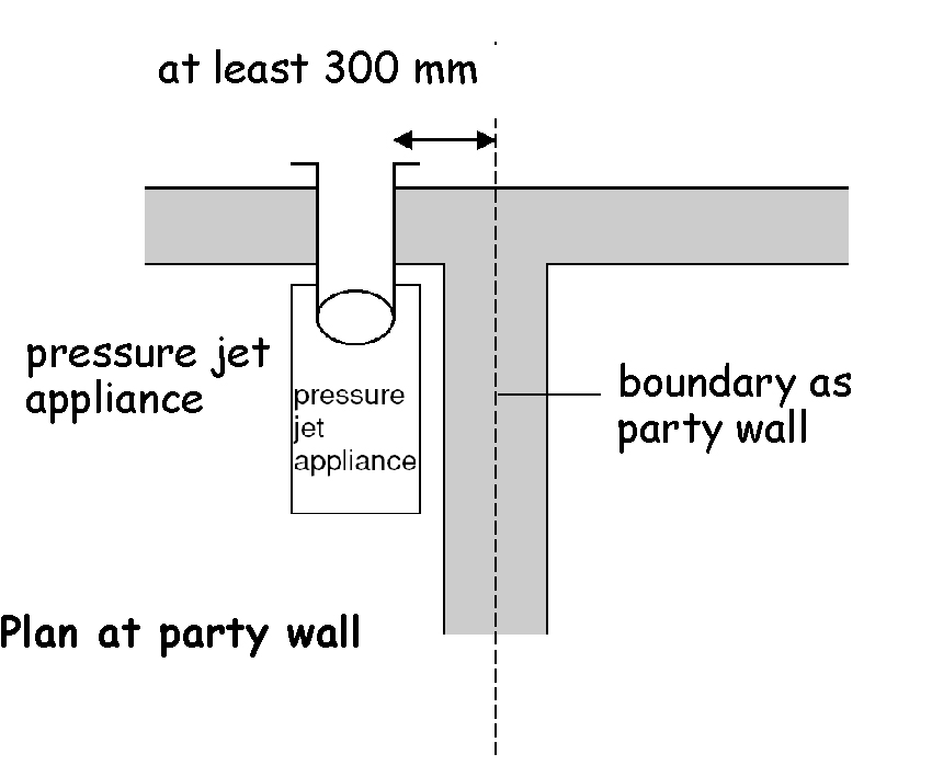
3.20.19 Gas-fired appliance flue outlets
The outlet from a flue should be located externally at a safe distance from any opening, obstruction or combustible material. The outlets should be located in accordance with the following diagram:
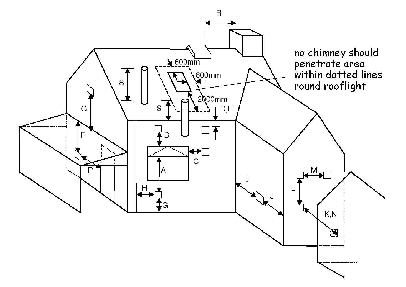
Table 3.18. Flue terminal positions for gas-fired appliances
| Location | Minimum distance to terminal in mm | |||
|---|---|---|---|---|
| Balanced flue, room-sealed appliance | Open flue | |||
| natural draught | fanned draught | natural draught | fanned draught | |
| A. Directly below an opening, air brick, opening window, etc | (0-7kW) 300 (>7-14kW) 600 (>14-32kW) 1500 (>32-70 kW) 2000 | 300 | n/app | 300 |
| B. Above an opening, air brick, opening window, etc | (0-32kW) 300 (>32-70kW) 600 | 300 | n/app | 300 |
| C. Horizontally to an opening, air brick, opening window, etc | (0-7kW) 300 (>7-14kW) 400 (>14-70kW) 600 | 300 | n/app | 300 |
| D. Below a gutter, or sanitary pipework | 300[2] | 75[1] | n/app | 75[1] |
| E. Below the eaves | 300[2] | 200 | n/app | 200 |
| F. Below a balcony or carport roof | 600 | 200 | n/app | 200 |
| G. Above ground, roof or balcony level | 300 | 300 | n/app | 300 |
| H. From vertical drain/soil pipework | 300 | 150[3] | n/app | 150 |
| I. From an internal or external corner | 600 | 300 | n/app | 200 |
| J. From a surface or boundary facing the terminal [4] | 600 | 600[5] | n/app | 600 |
| K. Vertically from terminal on same wall | 1500 | 1500 | n/app | 1500 |
| L. Horizontally from terminal on same wall | 300 | 300 | n/app | 300 |
| M. From a terminal facing the terminal | 600 | 1200[6] | n/app | 1200 |
| N. From an opening in a carport (e.g. door, window) into the building | 1200 | 1200 | n/app | 1200 |
| O. From a vertical structure on the roof [7] | n/app | n/app | [note 8] | n/app |
| P. Above an intersection with the roof | n/app | [note 9] | [note 10] | 150 |
Additional information:
1.Notwithstanding the dimensions in the table, a terminal serving a natural draught and fanned draught appliance of more than 3kW heat input, should be at least 300mm and 150mm respectively from combustible material.
2.Where a natural draught flue terminates not more than 1m below a plastic projection or not more than 500mm below a projection with a painted surface, then a heat shield at least 1m long should be fitted.
3.This dimension may be reduced to 75mm for appliances of up to 5kW heat input.
4.The products of combustion should be directed away from discharging across a boundary.
5.The distance from a fanned draught appliance terminal installed at right angles to a boundary may be reduced to 300mm in accordance with diagram 2 to clause 3.20.17.
6.The distance of a fanned flue terminal located directly opposite an opening in a building should be at least 2m.
7.Vertical structure includes a chimney-stack, dormer window, tank room, lift motor room or parapet.
8.1500mm if measured to a roof terminal, otherwise as Table 2 in BS 5440-1: 2000.
9.To manufacturer’s instructions.
10.As Table 2 in BS 5440-1: 2000.
11.n/all = not allowed. n/app = not applicable.
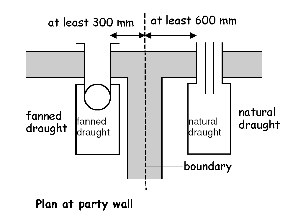
3.20.20 Carbon monoxide detection
Carbon monoxide (CO) is a colourless, odourless, and tasteless gas. Low levels of CO gas can be present in the atmosphere, however, it is highly toxic and dangerous to humans and animals in higher quantities. The gas is produced in high levels from appliances where incomplete combustion of a carbon based fuel occurs. Incomplete combustion could occur in appliance installations that are defective, lack proper maintenance or have inadequate provision for combustion air.
In order to alert sleeping occupants to the presence of levels of carbon monoxide which may be harmful to people, a detection/alarm system should be installed in all non-domestic residential buildings where a new or replacement fixed combustion appliance is installed.
Carbon monoxide detector/alarm systems installed within non-domestic buildings should be suitable for use in a commercial environment and should be permanently installed. They may be self contained detector and alarm units powered by a battery designed to operate for the working life of the detector or they may be hard wired mains operated, either with a built in sounder or connected to a central control panel. The detector should incorporate a warning device to alert the users when the working life of the detector is due to expire or, if mains operated, fitted with a sensor failure warning device.
Where carbon monoxide detectors are within the scope of either or both:
•European Directive 2006/95/EC – Low Voltage Directive, and/or
•European Directive 1999/5/EC – Radio and Telecommunication Terminal Equipment Directive
they should be constructed to fully comply with all applicable safety aspects of the Directive(s).
A carbon monoxide detection system to alert occupants to the presence of carbon monoxide should consist of:
•1 carbon monoxide detector in every space containing a combustion appliance (excluding an appliance used solely for cooking), and
•1 carbon monoxide detector to provide early warning to high risk accommodation, for example a bedroom, where a flue passes through these rooms.
Unless otherwise indicated by the manufacturer, carbon monoxide detectors should be either:
•ceiling mounted and positioned at least 300mm from any wall, or
•wall mounted and positioned at least 150mm below the ceiling and higher than any door or window in the room.
Carbon monoxide detectors in the space containing a fixed combustion appliance should be sited between 1m and 3m from the appliance.
Note: where the combustion appliance is located in a small space it may not be possible to locate the detector within that space. In such circumstances the detector may be located at the appropriate distance outwith the space.
A carbon monoxide detector should not be sited:
•in an enclosed space (for example in a cupboard or behind a curtain
•where it can be obstructed (for example by furniture)
•directly above a sink
•next to a door or window
•next to an extract fan
•next to an air vent or similar ventilation opening
•in an area where the temperature may drop below -10°C or exceed 40°C, unless it is designed to do so
•where dirt and dust may block the sensor
•in a damp or humid location, or
•in the immediate vicinity of a cooking appliance.
Carbon monoxide detectors that are located in areas that staff will not normally frequent, for example, those located within boiler rooms, should be linked to a visual or audible alarm or control panel sited at a staffed location, such as a reception desk.
In smaller non-domestic premises, for example guest houses, the guidance provided within clause 3.20.20 of the Domestic Technical Handbook may be followed.
The provision of a carbon monoxide detection system should not be regarded as a substitute for the correct installation and regular servicing of a combustion appliance.
3.21 Combustion appliances – air for combustion
#Source page 65
Mandatory Standard
| Standard 3.21 Every building must be designed and constructed in such a way that each fixed combustion appliance installation receives air for combustion and operation of the chimney so that the health of persons within the building is not threatened by the build-up of dangerous gases as a result of incomplete combustion. |
3.21.0 Introduction
All combustion appliances need ventilation to supply them with oxygen for combustion. This air, which must be replaced from outside the building, generally comes from the room in which the combustion appliance is located although many appliances are now located in specially constructed cupboards or appliance compartments. Ventilation of these cupboards or appliance compartments is essential to ensure proper combustion. Ventilation is also needed to ensure the proper operation of flues, or in the case of flueless appliances, to ensure the products of combustion are safely dispersed to the outside air.
Failure to provide adequate replacement air to a room can result in the accumulation of poisonous carbon monoxide fumes.
Conversions - in the case of conversions, as specified in regulation 4, the building as converted shall meet the requirement of this standard (regulation 12, schedule 6).
3.21.1 Supply of air for combustion generally
A room containing an open-flued appliance may need permanently open air vents. An open-flued appliance needs to receive a certain amount of air from outside dependant upon its type and rating. Infiltration through the building fabric may be sufficient but above certain appliance ratings permanent openings are necessary.
Ventilators for combustion should be located so that occupants are not provoked into sealing them against draughts and noise. Discomfort from draughts can be avoided by placing vents close to appliances e.g. floor vents, by drawing air from intermediate spaces such as hallways or by ensuring good mixing of incoming air. Air vents should not be located within a fireplace recess except on the basis of specialist advice. Noise attenuated ventilators may be needed in certain circumstances.
Appliance compartment that enclose open-flued appliances should be provided with vents large enough to admit all the air required by the appliance for combustion and proper flue operation, whether the compartment draws air from the room or directly from outside.
The installation of a mechanical extract system should be checked against the recommendations in clause 3.17.9.
3.21.2 Supply of air for combustion to solid fuel appliances
A solid fuel appliance installed in a room or space should have a supply of air for combustion by way of permanent ventilation either direct to the open air or to an adjoining space (including a sub-floor space) that is itself permanent ventilated direct to the open air. An air supply should be provided in accordance with the following table:
Table 3.19. Supply of air for combustion
| Type of appliance | Minimum ventilation opening size [2] |
|---|---|
| Open appliance without a throat [1] | a permanent air entry opening or openings with a total free area of 50% of the cross-sectional area of the flue. |
| Open appliance with a throat [1] | a permanent air entry opening or openings with a total free area of 50% of the throat opening area. |
| Any other solid fuel appliance | a permanent air entry opening or openings with a total free area of 550mm2 for each kW of combustion appliance rated output more than 5kW. (A combustion appliance with an output rating of not more than 5kW has no minimum requirement, unless stated by the appliance manufacturer). |
Additional information:
1.THROAT means the contracted part of the chimney flue lying between the fireplace opening and the main chimney flue.
2.Where a draught stabiliser is fitted to a solid fuel appliance, or to a chimney or flue-pipe in the same room as a solid fuel appliance, additional ventilation opening should be provided with a free area of at least 300mm2/kW of solid fuel appliance rated output.
3.Nominal fire size is related to the free opening width at the front of the fireplace opening.
3.21.3 Supply of air for combustion to oil-firing appliances
An oil-firing appliance installed in a room or space should have a supply of air for combustion by way of permanent ventilation either direct to the open air or to an adjoining space which is itself permanently ventilated direct to the open air. This also includes a sub-floor space. However this may not be necessary if it is a room-sealed appliance. An air supply should be provided in accordance with the recommendations in BS 5410: Part 1: 1997 or OFTEC Technical Book 3.
3.21.4 Supply of air for combustion to gas-fired appliances
A gas-fired appliance installed in a room or space should have a supply of air for combustion. An air supply should be provided in accordance with the following recommendations:
a.BS 5871-3: 2005, for a Decorative fuel-effect gas appliance
b.BS 5871-2: 2005, for an inset live fuel-effect gas appliance
c.BS 5440-2: 2000, for any other gas-fired appliance.
3.21.5 Flue-less gas heating appliances
Flue-less gas heating appliances obtain the necessary air for combustion and disperse the products of combustion from and to the room or space within which they are located. As condensation could occur when flue-less appliances are used as the only means of heating a room or space then not withstanding BS 5440-2:2000, the appliance standard BS 5871-4: 2007 provides additional installation and ventilation guidance for independent flue-less gas fires, convector heaters and heating stoves with a heat input of not more than 6kW in a domestic building or a commercial building.
3.22 Combustion appliances – air for cooling
#Source page 66
Mandatory Standard
| Standard 3.22 Every building must be designed and constructed in such a way that each fixed combustion appliance installation receives air for cooling so that the fixed combustion appliance installation will operate safely without threatening the health and safety of persons within the building. |
3.22.0 Introduction
In some cases, combustion appliances may need air for cooling in addition to air for combustion. This air will keep control systems in the appliance at a safe temperature and/or ensure that casings remain safe to touch.
Conversions - in the case of conversions, as specified in regulation 4, the building as converted shall meet the requirement of this standard (regulation 12, schedule 6).
3.22.1 Appliance compartments
Where appliances require cooling air, appliance compartments should be large enough to enable air to circulate and high and low level vents should be provided.
3.22.2 Supply of air for cooling to oil-firing appliances
An oil-firing appliance installed in an appliance compartment should have a supply of air for cooling by way of permanent ventilation, in addition to air for combustion, either direct to the open air or to an adjoining space. This also includes a sub-floor space. Air for cooling should be provided in accordance with the recommendations in BS 5410: Part 1: 1997 and in OFTEC Technical Book 3 for an oil-firing appliance located in an appliance compartment.
3.22.3 Supply of air for cooling to gas-fired appliances
A gas-fired appliance installed in an appliance compartment should have supply of air for cooling. Air for cooling should be provided in accordance with the recommendations in BS 5440: Part 2: 2000 for a gas-fired appliance located in an appliance compartment.
3.23 Fuel storage – protection from fire
#Source page 67
Mandatory Standard
| Standard 3.23 Every building must be designed and constructed in such a way that Limitation: This standard does not apply to portable containers. |
3.23.0 Introduction
The guidance on oil relates only to its use solely where it serves a combustion appliance providing space heating or cooking facilities in a building. There is other legislation covering the storage of oils for other purposes. Heating oils comprise Class C2 oil (kerosene) or Class D oil (gas oil) as specified in BS 2869: 2006.
It is considered unlikely that a fire will originate from the stored oil. It is the purpose of this guidance therefore, to ensure that a fire that may originate from a building, or other external source, is not transferred to the tank contents, or if a fire does occur, its effects are limited.
The acceptance of climate change and the environmental policies put in place to mitigate its impact are pushing the commercial introduction of renewable energy technologies to displace the use of fossil fuels and the related combustion emissions of greenhouse gases. Woody biomass can be used as an alternative to fossil fuels and in some EU countries biomass fuel is the principal source of renewable energy for heating applications. The carbon dioxide emitted when biomass is burnt can be considered to be offset by the carbon dioxide absorbed as trees grow. Whilst this does not compensate for the energy used in processing the wood for fuel, the carbon dioxide emissions are considerably less than those of fossil fuels.
The use of woody biomass, in the form of wood chips, wood pellets and logs may offer a viable alternative to fossil fuels, particularly in areas not served by the gas grid, although the supply and distribution of chips and pellets is, as yet, poorly developed in Scotland.
Conversions - in the case of conversions, as specified in regulation 4, the building as converted shall meet the requirement of this standard (regulation 12, schedule 6).
3.23.1 Separation of oil tanks from buildings and boundaries
Every fixed oil tank with a capacity of more than 90 litres should be located at a distance from a building to reduce the risk of the fuel that is being stored from being ignited if there is a fire in the building. Some fire protection to, or for, the building is required if the oil tank is located close to the building. Further guidance may be obtained from OFTEC Technical Book 3.
Precautions should also be taken when an oil storage tank is located close to a boundary. The installation of a tank should not inhibit full development of a neighbouring plot.
Large tanks - an oil tank with a capacity of more than 3500 litres should be located in accordance with the recommendations in BS 5410: Part 2: 1978.
Small tanks - an oil tank with a capacity of not more than 3500 litres should be located in accordance with the following table:
Table 3.20. Location of oil storage tank not more than 3500 litres capacity
| Location of tank | Protection recommended | |
|---|---|---|
| Building without openings | Building with openings | |
| Not more than 1.8m from any part of any building | non-combustible base; and any part of the eaves not more than 1.8m from the tank and extending 300mm beyond each side of the tank must be non-combustible and either: | non-combustible base; and any part of the eaves not more than 1.8m from the tank and extending 300mm beyond each side of the tank must be non-combustible and a barrier between the tank and any part of a building not more than 1.8m from the tank. |
| More than 1.8m from any building | non-combustible base | |
| Not more than 760mm from a boundary | non-combustible base, and a barrier, or a wall with a non-combustible construction type 7, short duration [2] | |
| More than 760mm from a boundary | non-combustible base | |
| Externally, wholly below ground | no protection required |
Additional information:
1.BARRIER means an imperforate, non-combustible wall or screen at least 300mm higher and extending 300mm beyond either end of the tank, constructed so as to prevent the passage of direct radiated heat to the tank.
2.See Section 2, Fire, annex 2.D.1.
3.23.2 Additional fire protection
The fuel feed system from the storage tank to the combustion appliance is also a potential hazard in the event of fire. The fire valve on the fuel feed, should be fitted in accordance with Section 8.3 of BS 5410: Part 1: 1997 and OFTEC Technical Book 3.
Oil pipelines located inside a building should be run in copper or steel pipe. The recommendations of Clause 8.2 of BS 5410: Part 1: 1997 should be followed.
Fire can also spread to an oil storage tank along the ground. Provision should therefore be made to prevent the tank becoming overgrown such as a solid, non-combustible base in full contact with the ground. A base of concrete at least 100mm thick or of paving slabs at least 42mm thick that extends at least 300mm beyond all sides of the tank would be appropriate. However, where the tank is within 1m of the boundary and not more than 300mm from a barrier or a wall of non-combustible construction type 7, short duration (see table to 2.B.1), the base need only extend as far as the barrier or wall.
3.23.3 Storage within a building
Where a storage tank is located inside a building, additional safety provisions should be made including the following:
a.the place where the tank is installed should be treated as a place of special fire risk, and
b.the space should be ventilated to the external air, and
c.the space should have an outward opening door that can be easily opened without a key from the side approached by people making their escape, and
d.there should be sufficient space for access to the tank and its mountings and fittings, and
e.a catchpit as described in the guidance to Standard 3.24.
Guidance on protection from spillage is provided to Standard 3.24.
Further guidance may be obtained from OFTEC Technical Book 3 for garage installations.
3.23.4 Bulk storage of woody biomass fuel
By its very nature woody biomass fuel is highly combustible and precautions need to be taken to reduce the possibility of the stored fuel igniting. To ensure maximum energy from the fuel all storage arrangements should be designed to be damp free and improve or maintain the moisture content of the fuel.
To inhibit the spread of fire to their contents, bulk storage for wood fuels should be located in accordance with the following table:
Table 3.21. Bulk storage of woody biomass fuel
| Location of container | Protection recommended |
|---|---|
| External and not more than 1.8m from any part of any building | |
| External not more than 1m from any boundary | the container should be constructed to have medium fire resistance duration to its boundary walls |
| Within a building |
Additional information:
1.BARRIER means an imperforate, non-combustible wall or screen at least 300mm higher than and extending 300mm beyond either end of the container constructed so as to prevent the passage of direct radiated heat.
2.See Section 2, Fire, annex 2.D.1.
Wood pellets can be damaged during delivery thus producing dust that can cause an explosion and precautions need to be taken to reduce this risk. Once a year any dust that has collected in the store should be removed.
Storage containers for wood pellets, where they are to be pumped from a transporter to the container, should include a protective rubber mat over the wall to reduce the damage to the pellets when they hit the wall. Containers should have an outward opening door incorporating containment to prevent the pellets escaping when the door is opened.
To maintain fire proof storage and prevent back-burning, there should be an interruption to the fuel transport system normally by use of a star-feeder or chute for the fuel to fall into the boiler. The installation should be in accordance with the safety standards described in BS EN 303-5: 1999.
The woody biomass fuel should be stored separately from the boiler that the fuel feeds for fire safety reasons.
3.24 Fuel storage – containment
#Source page 68
Mandatory Standard
| Standard 3.24 Every building must be designed and constructed in such a way that: Limitation: This standard does not apply to portable containers. |
3.24.0 Introduction
Oil is a common and highly visible form of water pollution. Because of the way it spreads, even a small quantity can cause a lot of harm to the aquatic environment. Oil can pollute rivers, lochs, groundwater and coastal waters killing wildlife and removing vital oxygen from the water. Large quantities of water are taken from rivers and groundwater for use as drinking water and for irrigation. Oil contamination can make water unfit for these purposes.
Oil accounts for about a third of all reported pollution incidents in Scotland that are investigated by SEPA each year. That means around 500 to 600 pollution incidents a year with about 10 to 12% being serious. It is an offence to cause pollution and courts now impose heavy fines.
Oil is a ‘List I’ substance within the meaning of the EC Groundwater Directive (80/68/EEC). The UK government is required by this directive to prevent List I substances from entering groundwater and to prevent groundwater pollution by List II substances.
The storage of oil is a controlled activity under the Water Environment (Controlled Activities)(Scotland) Regulations 2005 and will be deemed to be authorised if it complies with The Water Environment (Oil Storage)(Scotland) Regulations 2006. Enforcement is by SEPA.
Conversions - in the case of conversions, as specified in regulation 4, the building as converted shall meet the requirement of this standard (regulation 12, schedule 6).
3.24.1 Construction of oil storage tanks
Fixed oil storage tanks between 90 and 2500 litres and the fuel feed system connecting them to a combustion appliance should be strong enough to resist physical damage and corrosion so that the risk of oil spillage is minimised. Tanks should be constructed in accordance with:
a.the recommendations of BS 799: Part 5: 1987, for a steel tank, or
b.the recommendations of OFTEC Technical Standard OFS T200, for a steel tank, with or without integral bunding, or
c.the recommendations of OFTEC Technical Standard OFS T100, for a polyethylene tank with or without integral bunding, or
d.a European harmonised product standard and assessed by a notified body.
3.24.2 Installation of oil storage tanks
Tanks with a capacity more than 3500 litres and the fuel feed system connecting them to a combustion appliance should be installed in accordance with the recommendations of BS 5410: Part 2: 1978.
Small tanks - tanks with a capacity of more than 90 litres but not more than 3500 litres and the fuel feed system connecting them to a combustion appliance should be installed in accordance with the recommendations of BS 5410: Part 1: 1997.
Underground tanks - reference should be made to the Code of Practice for the Owners and Operators of Petrol Stations and Other Fuel Dispensing/Storage Facilities Involving Underground Storage Tanks. This CoP provides guidance on underground and partially buried oil storage tanks. The Scottish Executive has also produced a code of practice for owners and operators of underground storage tanks under the Groundwater Regulations.
Care should be taken to prevent leakage from pipework. Pipework should be run so as to provide the most direct route possible from the tank to the burner. Joints should be kept to a minimum and the use of plastic coated malleable copper pipe is recommended. Pipework should be installed in accordance with the recommendations in BS 5410: Parts 1: 1997 and Part 2:1978 and OFTEC Technical Book 3.
3.24.3 Secondary containment
It is necessary for a wide variety of possible hazards to be considered as to whether a catchpit (bund) is required or not. BS 5410: Part 1: 1997 highlights 2, as the size of the tank and its proximity to a watercourse. However other potential hazards should be borne in mind and a risk assessment should be carried out for each installation. It is preferable for installers to keep a record of this and OFTEC Technical Book 3 provides a simple crosscheck. The full list of potential hazards listed by OFTEC are:
a.tank within 10m of a watercourse
b.tank located where spillage could run into an open drain or to a loose fitting manhole cover
c.tank within 50m of a borehole or spring
d.tank over ground where conditions are such that oil spillage could run-off into a watercourse
e.tank located in a position where the vent pipe outlet is not visible from the fill point
f.any other potential hazard individual to the site.
Catchpit (bund) - if any of the above conditions apply, the oil storage tank should be provided with a catchpit. A catchpit means a pit, without a drain, which is capable of containing the contents of the tank, plus 10%.
An integrally bunded tank is a tank, together with a catchpit, manufactured as a self-contained unit complete with a removable lid and designed to contain the escape of any liquid escaping from the tank in an overfill situation.
A catchpit or integrally bunded tank should be provided in accordance with the recommendations of OFTEC Standard OFS T100 and OFS T200 and
a.for tanks with a capacity of more than 3500 litres, clause 45.3 of BS 5410: Part 2: 1978
b.for tanks with a capacity of not more than 3500 litres, clause 6.5 of BS 5410: Part 1: 1997.
A catchpit should also be provided in the following situations:
Table 3.22. Provisions of a catchpit
| Location of tank | Catchpit or integrally bunded tank |
|---|---|
| Within a building | recommended |
| External, above ground (2500 litres or less) | in accordance with clause 3.24.3 |
| External, wholly below ground | not required |
3.24.4 Storage containers for solid biomass fuel
In order to best exploit the advantages achieved through the use of woody biomass as low carbon technology it is recommended that wood fuel storage provision is of a size that will ensure bulk deliveries need not be made at intervals of less than 1 month.
Deliveries of wood pellets may be less frequent than deliveries of wood chips because pellets can have 3 times the calorific value of dry wood chips. Alternatively, the storage volume can be smaller for the same energy capacity.
The following table provides recommendations for some building types of varying size on the storage recommendations that will permit a large enough volume to be delivered whilst minimising vehicle movements. The table is intended to provide an estimate of fuel storage based on heat demand and to help with initial studies. A more systematic exercise should be carried out during development of the scheme design. Advice on the sizing of storage for woody biomass fuel for smaller buildings is provided in the non-domestic Technical Handbook.
Table 3.23. Woody fuel storage recommendations for 100% heating
| Building type (m2) | Heat demand (annual) | Wood chips | Wood pellets | ||
|---|---|---|---|---|---|
| MW hours | Fuel required (m3/year) | Storage | Fuel required (m3/year) | Storage | |
| Education (400-2000) | 90-450 | 110-565 | 10-60 m3 | 40-210 | 5-20 m3 |
| Industrial (100-2000) | 20-360 | 25-450 | 5-55 m3 | 10-165 | 5-20 m3 |
| Office (100-2000) | 20-420 | 25-525 | 5-55 m3 | 10-195 | 5-15 m3 |
Additional information:
1.Figures represent monthly deliveries.
2.The storage recommendations relate to buildings constructed in accordance with the guidance in the 2007 edition of Section 6, Energy. Storage for buildings constructed to higher standards of energy conservation may be reduced, whilst storage for buildings constructed to earlier standards should be increased to equivalent.
3.Recommended storage capacity to meet 100% of the space and DHW heating demand assuming storage capacity is 25% larger than delivery size.
3.25 Solid waste storage
#Source page 69
Mandatory Standard
| Standard 3.25 Every building must be designed and constructed in such a way that accommodation for solid waste storage is provided which: Limitation: This standard applies only to a dwelling. |
3.25.0 Introduction
This standard does not apply to buildings other than domestic buildings.
3.26 Dungsteads and farm effluent tanks
#Source page 70
Mandatory Standard
| Standard 3.26 Every building must be designed and constructed in such a way that there will not be a threat to the health and safety of people from a dungstead and farm effluent tank. |
3.26.0 Introduction
Silage effluent is the most prevalent cause of point source water pollution from farms in Scotland. A high proportion of serious pollution incidents occur each year through failure to contain or dispose of effluent satisfactorily.
Collection, storage and disposal of farm effluent and livestock wastes are all stages when pollution can occur. These materials are generally classified by type of stock and physical form. This may be solid, semi-solid or liquid. Solids are stored in dungsteads that must be properly drained and the effluent collected in a tank while liquids are stored in tanks above or below ground. The container must be impermeable.
The guidance to this standard should not be read in isolation. Appropriate sections of other legislation, such as the Control of Pollution (Silage, Slurry and Agricultural Fuel Oil) (Scotland) Regulations 2003 and The Water Environment (Controlled Activities) (Scotland) Regulations 2011, as amended would also normally require to be met. The Scottish Environment Protection Agency is the body responsible for enforcing these environmental regulations and further information may be obtained from their website www.sepa.org.uk.
The Code of Good Practice for the Prevention of Environmental Pollution from Agricultural Activity is a practical guide for farmers, growers, contractors and others involved in agricultural activities, on whom there is a statutory obligation to avoid causing pollution to the environment. The Code provides helpful guidance on the planning, design, construction, management and land application of slurries and silage effluent that can give rise to pollution of water, air or soil environments. SEPA is the body responsible for enforcing these regulations.
Explanation of terms – the following terms are included to provide clarity to their meaning in the guidance to this standard.
Dungstead means a permanent storage facility for all farmyard manures including solid and semi-solid animal excreta. The construction should allow for any liquid to be contained within the store or be allowed to seep out for collection in a leak-proof storage tank.
Farm Effluent Tank means a leak-proof storage facility for liquid animal excreta (slurry), dirty water (water contaminated with slurry) and silage effluent that is of a consistency that allows it to be pumped or discharged by gravity at any stage of the handling process.
Conversions - in the case of conversions, as specified in regulation 4, the building as converted shall meet the requirement of this standard (regulation 12, schedule 6).
3.26.1 Construction of dungsteads and farm effluent tanks
Every dungstead or farm effluent tank, including a slurry or silage effluent tank should be constructed in such a manner so as to prevent the escape of effluent through the structure that could cause ground contamination or environmental pollution.
The construction should also prevent seepage and overflow that might endanger any water supply or watercourse.
3.26.2 Location of dungsteads and farm effluent tanks
Every dungstead or farm effluent tank, including a slurry or silage effluent tank should be located at a distance from a premises used wholly or partly for the preparation or consumption of food so as not to prejudice the health of people in the food premises. The dungstead or farm effluent tank should be located at least 15m from the food premises.
3.26.3 Safety of dungsteads and farm effluent tanks
Where there is the possibility of injury from falls, a dungstead or farm effluent tank should be covered or fenced to prevent people from falling in. Covers or fencing should be in accordance with the relevant recommendations of Section 8 of BS 5502: Part 50: 1993.
4.0 Introduction
#Source page 71
4.0.1 Background
Safety has been defined by the International Standards Organisation as ‘a state of freedom from unacceptable risks of personal harm’. This recognises that no activity is absolutely safe or free from risk. No building can be absolutely safe and some risk of harm to users may exist in every building. Building standards seek to limit risk to an acceptable level by identifying hazards in and around buildings that can be addressed through the Building (Scotland) Regulations.
Deaths and serious injury to people in and around buildings occur in significant numbers from accidents involving falls, collisions, entrapment, scalding, electrocution or malfunction of fittings. Designers need to consider carefully all aspects of design to minimise risks inherent in any building.
Safety - good practice - not all issues relating to good practice are covered in this Technical Handbook. Publications by organisations including the Health and Safety Executive http://www.hse.gov.uk/ and the Royal Society for Prevention of Accidents (RoSPA) http://www.rospa.com/ offer further information relevant safety of occupants of, and visitors to, buildings.
Accessibility - buildings should be designed to address safety and the welfare and convenience of building users. An inclusive environment is one within which everyone, regardless of age, disability or circumstance, can make use of facilities safely, conveniently and without assistance to the best of their ability. In this respect, other legislation also has a bearing on access in buildings.
The Equality Act 2010 came into force on 1 October 2010. The Act simplified and strengthened over 116 separate pieces of legislation (including the Disability Discrimination Act 1995 and Disability Equality Duty 2006) into one single Act. Combined, they provide a legal framework to protect the rights of individuals and advance equality of opportunity for all.
It has a much wider remit than the building regulations, applying as it does to owners and operators of all buildings, new and existing, that lie within its scope. To assist parties who have a duty under this Act to familiarise themselves with its requirements, the Equality and Human Rights Commission has produced a range of guidance literature. Designers, clients and developers should consider the duties imposed under the Equality Act and are recommended to study the legislation and guidance.
With respect to providing suitable access and facilities for people with a disability, consideration should be given to equality requirements including:
•Equality law recognises that bringing about equality for disabled people may mean changing the way in which services are delivered, providing extra equipment and/or the removal of physical barriers. This is the ‘duty to make reasonable adjustments’.
•The duty to make reasonable adjustments aims to make sure that a disabled person can use an organisation’s services as close as it is reasonably possible to the standard usually offered to non-disabled people.
•If an organisation providing goods, facilities or services to the public or carrying out public functions, or running an association identifies barriers to disabled people in how it does things, it must consider making adjustments. If those adjustments are reasonable for that organisation to make, then it must make them.
•The duty is ‘anticipatory’. An organisation cannot wait until a disabled person wants to use its services, but must think in advance (and on an ongoing basis) about what disabled people might reasonably need.
Access statements - many designers and developers are familiar with the use of an access statement as a means of assisting in the delivery of more inclusive buildings. This records how access issues have been considered and developed from project inception, through all stages of development, to the operation and management of a building.
Where design proposals vary from guidance within this Handbook or, in the case of a conversion where a standard is to be met as far as is reasonably practicable, relevant information extracted from a project access statement may assist in determining compliance.
4.0.2 Aims
The intention of this section is to give recommendations for the design of buildings that will ensure access and usability and reduce the risk of accident. The standards within this section:
•ensure accessibility to and within buildings and that areas presenting risk through access are correctly guarded, and
•reduce the incidence of slips, trips and falls, particularly for those users most at risk, and
•ensure that electrical installations are safe in terms of the hazards likely to arise from defective installations, namely fire and loss of life or injury from electric shock or burns, and
•prevent the creation of dangerous obstructions, ensure that glazing can be cleaned and operated safely and to reduce the risk of injury caused by collision with glazing or unsafe access to, and on, roofs, and
•safely locate hot water and steam vent pipe outlets, and minimise the risk of explosion through malfunction of unvented hot water storage systems and prevent scalding by hot water from sanitary fittings, and
•ensure the appropriate location and construction of storage tanks for liquefied petroleum gas.
4.0.3 Latest changes
The following is a summary of the main change that has been introduced since 1 October 2015.
•Standard 4.14 - Introduction of a new standard and supporting guidance covering the provision of in-building physical infrastructure to facilitate the installation of high-speed electronic communications networks.
•Appendix A - Additional defined terms added. Most of these new terms are as defined within Article 2 of EU Directive 2014/61/EU.
4.0.4 Relevant legislation
Listed below are some pieces of legislation that may be relevant and/or helpful to those using the guidance in this particular section.
The Equality Act 2010 sets out measures intended to end discrimination against people with disabilities in the areas of employment, access to goods, facilities and services, in the management, buying or renting of land or property, in education and in public transport.
The Workplace, (Health, Safety and Welfare) Regulations 1992 cover the key issues for inspection and enforcement by local authorities on matters relating to the physical characteristics of the workplace such as temperature, lighting, cleanliness and sanitary conveniences.
The Electricity Safety, Quality and Continuity Regulations 2002 defines the duties of any party supplying electricity to premises with regard to matters such as supply, equipment, protection and provision of earthing.
The Electricity at Work Regulations 1989 defines the duties of an employer to ensure and maintain a safe working environment with respect to any electrical installation within a building.
The Gas Safety (Installations and Use) Regulations 1998 require that any person who installs, services, maintains, removes, or repairs gas fittings must be competent. It covers not only materials, workmanship, safety precautions and testing of gas fittings but also the safe installation of all aspects of gas-fired combustion appliance installations.
The Work at Height Regulations 2005 apply to all work at height where there is a risk of a fall liable to cause personal injury. They place duties on employers, the self-employed, and any person who controls the work of others, such as facilities managers or building owners who may contract others to work at height.
4.0.5 Certification
Scottish Ministers can, under Section 7 of the Building (Scotland) Act 2003, approve schemes for the certification of design or construction for compliance with the mandatory functional standards. Such schemes are approved on the basis that the procedures adopted by the scheme will take account of the need to co-ordinate the work of various designers and specialist contractors. Individuals approved to provide certification services under the scheme are assessed to ensure that they have the qualifications, skills and experience required to certify compliance for the work covered by the scope of the scheme. Checking procedures adopted by Approved Certifiers will deliver design or installation reliability in accordance with legislation.
The certification of construction (electrical installations to BS 7671) scheme has been approved by Scottish Ministers to confirm compliance with relevant standards in Section 4 http://www.scotland.gov.uk/topics/built-environment/building/building-standards.
4.1 Access to buildings
#Source page 72
Mandatory Standard
| Standard 4.1 Every building must be designed and constructed in such a way that all occupants and visitors are provided with safe, convenient and unassisted means of access to the building. Limitation: There is no requirement to provide access for a wheelchair user to: |
4.1.0 Introduction
An inclusive approach to design should be taken to ensure that buildings are as accessible to as wide a range of people as possible. Solutions should be integral to a design rather than an afterthought added in order to meet duties under building standards or other legislation.
Inclusive design is not just relevant to buildings. It applies throughout any internal or external environment, wherever people go about everyday activities. It should be a continuous process, through all stages of the development of a building and involve potential users. Advice on this topic is available in the joint BSD/Scottish Executive Planning Division Planning Advice Note PAN 78: ‘Inclusive Design’ which promotes the merits of an inclusive approach to the design of the built environment.
All those that are involved in the design of buildings should be aware of their responsibilities under the Equality Act 2010, further details of which can be found in clause 4.0.1.
Whilst the guidance to this standard reflects general good practice, certain issues remain outwith the scope of the building regulations. There are numerous publications offering additional guidance on accessibility and inclusive design, including those listed below:
•BS 8300: 2009 – ‘Design of buildings and their approaches to meet the needs of disabled people – code of practice’
•'Inclusive Mobility' – Department of Transport, 2002
•‘Guidance on the Use of Tactile Paving Surfaces’, published jointly by The Scottish Office and the Department for the Environment, Transport and the Regions (DETR).
Conversions - in the case of conversions, as specified in regulation 4, the building as converted shall meet the requirements of this standard in so far as is reasonably practicable, and in no case be worse than before the conversions (regulation 12, schedule 6).
4.1.1 Car parking
The need for car parking serving a building will commonly be determined by a developer and may also be a condition of planning permission. Where car parking is provided within the curtilage of a building, it should include accessible spaces.
A proportion of car parking spaces should be designed to be accessible to a person with mobility impairment, including a wheelchair user, and designated for use as such. These parking spaces should be:
a.provided on a ratio of at least 1 per 20 parking spaces, or part thereof, and
b.located on a road surface that is level (with a gradient of not more than 1 in 50), and
c.not more than 45m from a common entrance, and
d.clearly marked with the international symbol of access, and
e.provided with a dropped kerb access to an accessible route, and
f.where perpendicular or at an angle to a road, at least 4.8m long x 2.4m wide, outwith which a delineated access zone at least 1.2m wide to each long side and between the end of the bay and any road is shown, or
g.where parallel to a road, at least 6.6m long by 3.6m wide, as shown below.
Planning legislation - reference should also be made to SPP 17: ‘Planning for Transport’ where a more onerous provision than noted in sub-clause (a) above may be recommended for certain building types.
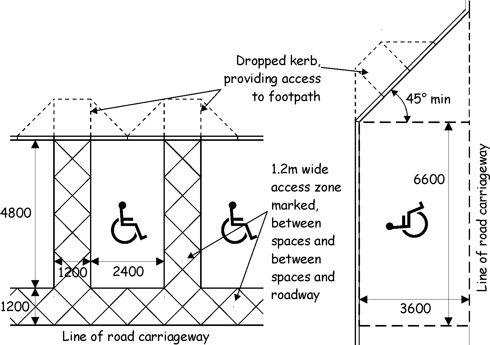
To allow operation by a person who uses a wheelchair, equipment such as ticket dispensers, located in pedestrian areas where there are accessible car parking spaces, should have any controls at a height of between 750mm and 1.2m above ground level.
4.1.2 Setting-down points
For the convenience of a person arriving at a building in a vehicle driven by another, where a road is provided within the curtilage of a building, there should be a setting-down point close to a principal entrance of each building.
This should be on a level surface, where the road gradient or camber is less than 1 in 50, with a dropped kerb between the road and an accessible route to the building.
On a busy vehicular route, such as a public highway, a setting-down point should be positioned outwith the road carriageway. As a person may require assistance in alighting from a vehicle, the size of the setting-down point should follow the recommendations for an on-street parking bay given in clause 4.1.1.
4.1.3 Accessible routes
Regardless of how they arrive within the curtilage of a building, a person should then be able to travel conveniently and without assistance to the entrance of a building. Routes to a building that are too steep, too narrow or poorly surfaced, or that contain steps or other obstructions, will make access difficult or impossible for many people. To prevent this, a route to an entrance should be provided that is accessible to everyone.
An accessible route should contain no barriers, such as kerbs, steps or similar obstructions that may restrict access. Street furniture can present a hazard, particularly to a wheelchair user or a person with a visual impairment and should be located outwith the width of an accessible route. Use of low-level bollards or chain-linked posts, for example, can be particularly hazardous.
There should be an accessible route to the principal entrance to a building, and to any other entrance that provides access for a particular group of people (for example, a staff or visitor entrance), from:
a.a road, and
b.any accessible car parking provided within the curtilage of the building.
There should also be an accessible route between accessible entrances of different buildings within the same curtilage.
Gradient of accessible route - as steeper gradients are more difficult to negotiate, level or gently sloping routes should be used where possible, in preference to ramps. An accessible route should be:
•level, which for the purpose of this guidance is a gradient of not more than 1 in 50, or
•gently sloping, which for the purpose of this guidance is a gradient of more than 1 in 50 and not more than 1 in 20, or
•ramped, with a gradient of more than 1 in 20 and not more than 1 in 12
the cross-fall on any part of an accessible route should not exceed 1 in 40.
Gently sloping gradients should be provided with level rest points of not less than 1.5m in length, at intervals dependent on the gradient of the sloping surface. This should follow the same relationship given for ramp flights, e.g. up to 20m apart for a slope of 1 in 30, 30m for a slope of 1 in 40 and so on.
Recommendations for ramps are provided in the guidance to Standard 4.3.
Complementary steps - ramps are not necessarily safe or convenient for an ambulant person with mobility impairment, and can be more difficult and dangerous to negotiate than steps. Therefore, any ramped access, having a rise of more than 300mm, should be complemented by an alternate, stepped means of access.
4.1.4 Surface of an accessible route
For safety and convenience in use, the surface of an accessible route should be firm, uniform and of a material and finish that will permit ease in manoeuvring. It should provide a degree of traction that will minimise the possibility of slipping. This should take into account both anticipated use and environmental conditions.
The surface of an accessible route, whether composed of modular paving units, formless materials such as tarmac, or another durable material, should have a profile that will not offer a trip hazard or result in standing water. It should be installed in accordance with a code of practice relevant to the material, where such exists.
Surface elements such as drainage gratings and manhole covers should be of a type that will not create a trip or entrapment hazard. Uneven surfaces, such as cobbles, or loose-laid materials, such as gravel, will present difficulties to many people and should not be used.
Tactile paving - at a location where the footpath is level with a road surface, such as at a dropped kerb, tactile paving should be used to provide warning to a person with a visual impairment of the presence of a vehicular route. Information on use of tactile paving on footpaths is given in 'Guidance on the Use of Tactile Paving Surfaces'.
4.1.5 Length of accessible routes
The longer a pedestrian route, the greater difficulty it can present to many people. Therefore, in addition to minimising gradients where possible, as recommended in clause 4.1.3, the length of an accessible route to an accessible entrance of a building should be limited to 45m.
In some projects, such as sports stadia or retail developments, a large number of accessible parking spaces may be provided. In such a case, it may not be reasonably practicable for every such space to be within 45m of a principal entrance. Where this is the case, resting points with seating positioned outwith the width of the accessible route should be provided at not more than 50m intervals on the route from the furthest spaces.
4.1.6 Width of accessible routes
The width of a pedestrian route to a building should reflect how it will be used. For example, most public footpaths are at least 1.8m wide, which allows two-way traffic under most circumstances.
Any part of an accessible route to a building from accessible parking spaces or a setting-down point should have a minimum surface width of 1.8m.
Elsewhere, the clear and unobstructed surface width of an accessible route should be not less than 1.2m, which will accommodate any person where traffic is in a single direction of travel. To allow for passing, localised widening of any route narrower than 1.8m wide to not less than 1.8m should be made at any junction and change of direction and, where the whole length of the route is not visible, also at not more than 10m intervals along the route.
On an accessible route, a level footpath of not less than 1.0m in width should be maintained to the rear of the slope to any dropped kerb.
Any gate across an accessible route should offer a clear opening width of at least 850mm.
Guidance to Standard 2.9 may further affect minimum width where an accessible route forms part of an escape route.
4.1.7 Accessible entrance
An entrance to a building that will be used as a principal means of access, including an entrance that provides access for a particular group of people, e.g. staff; or that offers a direct means of access between buildings, should be an accessible entrance, designed to present as little restriction to passage as possible.
An accessible entrance to a building should:
a.be readily identifiable from the general features of the building, and
b.have an unobstructed entrance platt, measuring at least 1.5m by 1.5m, with a crossfall of not more than 1 in 50, if required to prevent standing water, and
c.where secured by a lock or other access control system as part of the normal operation of the building, have a canopy, recessed entrance or similar means of protecting people entering the building from the elements, and
d.have an accessible threshold (see clause 4.1.9), and
e.have a door leaf which provides a clear opening width of at least 800mm in accordance with the diagram below, and
f.have a glazed vision panel, as described below, and
g.be provided with a securely fixed internal floor finish that will reduce tracking of dirt and moisture into the building that may cause a slip hazard and which should offer a firm surface for wheelchair traffic. Where reasonably practicable, this should be provided for a length of at least 1.8m, to allow for drying of both foot and wheeled traffic, and
h.if not a powered door, have an unobstructed space to the opening face of the door, next to the leading edge, of at least 300mm, and
i.if fitted with a door closing device, follows the recommendations in clause 4.2.6, and
j.where it includes a revolving door, also have an adjacent side hinged door in accordance with the points noted above.
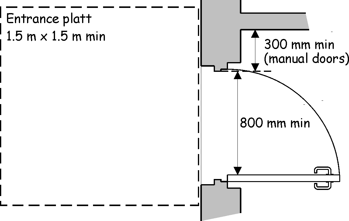
Weather protection - the form that weather protection should take will vary with location and exposure of the building. However an example of minimum provision might be a canopy or recess, 750mm deep, across the width of the entrance platt, with an underside not more than 2.3m above entrance level. It is recognised that there are circumstances where provision of weather protection may not be practicable or may be constrained by other permissions.
Clear opening width - the projection of ironmongery which extends across the width of a door leaf, such as an emergency push bar for escape or a horizontal grab rail, should be subtracted when calculating the clear opening width.
Glazed vision panels - to assist in preventing collisions, a clear glazed vision panel or panels to a door should give a zone of visibility from a height of not more than 500mm to at least 1.5m above finished floor level. This may be interrupted by a solid element between 800mm and 1.15m above floor level. A vision panel is not needed to a powered door controlled by automatic sensors or where adjacent glazing offers an equivalent clear view to the other side of a door.
Door entry systems - where an intercom or entry control system is provided, it should be positioned between 900mm and 1.2m above floor level. It should include an inductive coupler compatible with the ‘T’ setting on a personal hearing aid, together with a visual indicator that a call made has been received. Controls should contrast visually with surrounding surfaces and any numeric keypad should follow the 12-button telephone convention, with an embossed locater to the central ‘5’ digit.
4.1.8 Powered doors
Use of a powered door will improve accessibility at an entrance to a building. However care should be taken to ensure that the form of such a door does not present any additional hazard or barrier to use.
Powered doors should be controlled by either an automatic sensor, such as a motion detector, or by a manual activation device, such as push-pad. Any manual control should be located at a height of between 750mm and 1.0m above ground level and at least 1.4m from the plane of the door or, where the door opens towards the direction of approach, 1.4m from the front edge of the open door leaf. A manual control should contrast visually with the surface on which it is mounted.
In addition to the general recommendations for accessible entrances given in clause 4.1.7, a powered door should have:
•signage to identify means of activation and warn of operation, and
•sensors to ensure doors open swiftly enough and remain open long enough to permit safe passage in normal use and to avoid the door striking a person passing through, and
•if a swing door, identification of any opening vertical edge using visual contrast, and
•if on an escape route, or forming a lobby arrangement where the inner door is also powered or lockable, doors that, on failure of supply will either fail ‘open’ or have a break-out facility permitting doors to be opened in direction of escape, and
•guarding to prevent collision with, or entrapment by a door leaf, except where such guarding would prevent access to the door.
Guidance on safety aspects of automatic doors are given in BS 7036-1 to 5: 1996 – ‘Code of practice for safety at powered doors for pedestrian use’.
Large powered revolving doors can be more convenient to use than small revolving doors but may still present a hazard to some people. They should therefore always be complemented by an adjacent powered swing or sliding door.
4.1.9 Accessible thresholds
To be accessible, a door should not present unnecessary barriers to use, such as a step or raised profile at a threshold, that might present difficulties to a wheelchair user or be an entrapment or trip hazard to an ambulant person, whether or not using a walking aid.
An accessible threshold should be designed to prevent the ingress of rain and should be level where this is reasonably practicable.
Where, an upstand is proposed, any projection should have a height of not more than 15mm, with any vertical element of more than 5mm height being pencil-rounded or chamfered to an angle of not more than 45º to the horizontal.
4.2 Access within buildings
#Source page 73
Mandatory Standard
| Standard 4.2 Every building must be designed and constructed in such a way that: Limitation: There is no requirement to provide access for a wheelchair user: |
4.2.0 Introduction
Circulation areas within a building should allow occupants to move around freely and without difficulty, to the best of their ability. Lack of space can make movement around a building difficult for many people and hamper activities such as carrying or moving large items.
It is important to consider space provision and the form of access, both within and between storeys and particular elements of a building that may otherwise make use of a building difficult for many people.
All those involved in the design of buildings should also be aware of their responsibilities under the Equality Act 2010, further details of which can be found in clause 4.0.1.
Whilst the guidance to this standard reflects general good practice, certain issues remain outwith the scope of the building regulations. There are numerous publications offering additional guidance on accessibility and inclusive design, including those listed below:
•BS 8300: 2009 – ‘Design of buildings and their approaches to meet the needs of disabled people – code of practice’
•'Accessible Stadia' (Football Licensing Authority, 2003). This document provides useful guidance on accessibility issues relating specifically to assembly buildings such as sports stadia and arenas.
Conversions - in the case of conversions, as specified in regulation 4, the building as converted shall meet the requirements of this standard in so far as is reasonably practicable, and in no case be worse than before the conversion (regulation 12, schedule 6).
4.2.1 Access within buildings
A building should be accessible to everyone. It should be possible for a person to move throughout a building and use the facilities present to the best of their ability, without assistance and without the need to overcome unnecessary barriers.
Every storey and level of a building should be accessible. However it is recognised that it may not be necessary or, in some cases, reasonably practicable to provide full access to all parts of a building. Consequently, the following exceptions are noted.
Limited access - level access, or access by stair, ramp or lifting device need not be provided to any storey, or part of a storey:
•containing only fixed plant or machinery, the only normal visits to which are intermittent, for inspection or maintenance purposes, or
•where access must be restricted to suitably trained persons for health and safety reasons, such as walkways providing access only to process machinery or catwalks and working platforms reached by industrial ladder.
Stepped access - level or ramped access or access by a lift need not be provided:
•in a residential building, such as a hotel, to an upper storey or level containing neither communal facilities or accommodation, including bedrooms, designed to be accessible to a wheelchair user, or
•to a raised area, other than a gallery, within a storey of a restaurant, bar or similar building, which amounts to not more than half the public area, if all serving and other facilities are located on the accessible portion of the storey, or
•in a car parking structure, to a storey within which accessible parking spaces are not provided, unless that storey also contains facilities that are not available on another, accessible, storey, or
•within an area of fixed seating, other than to spaces provided for wheelchair users as recommended in guidance to Standard 4.10.
Small buildings - in small 2 storey buildings, ramped access or access by a lift need not be provided where:
•the total floor area of each storey is not more than 100m2and the full range of goods, services and facilities are available on the accessible storey, and
•the greater proportion of the service provision should be on the accessible storey, unless it can be shown that a lesser provision would be appropriate for the use of the building, such as ‘one to one’ consultancy, for example a dental surgery or beauty salon. However, where the service provision could mean a group of several customers gather together in the building for a period of time (for example, a restaurant) then the floor area of the room(s) used for providing that service should be greatest on the accessible storey.
Access between areas in buildings such as places of lawful detention may need to be restricted for security purposes. Where proposed, any such restrictions should be clearly identified.
4.2.2 Corridors
Corridors within a building should be wide enough to allow two-way traffic and manoeuvring at junctions or when passing through doorways. For example, a clear width of 1.8m is the minimum that will allow two wheelchair users to pass safely.
All corridors therefore should have an unobstructed width of at least 1.2m wide. This is the minimum width for escape recommended in Section 2, (Fire).
However where corridors are less than 1.8m in width, manoeuvring or passing spaces of not less than 1.8m in length and width and free of obstructions should be provided. These can be more easily incorporated at any change of direction and at junctions.
Obstructions - other than on a wall opposite a doorway, or in the areas noted above, an obstruction such as a radiator may project up to 100mm, reducing a corridor width to 1.1m, over a maximum length of 900mm.
Gently sloping surfaces - within a building, unidentified gradients may disorient building users and the need for gently sloping surfaces in rooms and on circulation routes should be considered carefully before use. Level rest points on gently sloping routes should be provided as recommended in clause 4.1.3. Where not extending across the full width of a room or corridor, guarding should be provided to any exposed edge of such an area as for a ramp flight, as noted in the guidance to Standard 4.4.
4.2.3 Floor surfaces
Floor surfaces to corridors and circulation areas within a building should be uniform, permit ease in manoeuvring and be of a material and finish that, when clean and dry, provides a level of traction that will minimise the possibility of slipping.
Where there is a change in the characteristics of materials on a circulation route, such as from a tile to carpet finish, transition should be level and, where reasonably practicable, differing surfaces should contrast visually to identify the change in material and reduce the potential for trips.
4.2.4 Lobbies
Use of a lobby can reduce the effect of external conditions on the interior of a building and may also contribute to fire safety. However where two sets of doors are located in close proximity, this can present a hazard and a potential barrier to access.
Any lobby provided at the entrance to or within a building should allow a person to pass through whilst remaining clear of the swing of doors. A rectangular area, of at least 1.6m long by 750mm wide, outwith any door swing, would permit safe passage of, for example, a person in a wheelchair and a companion.
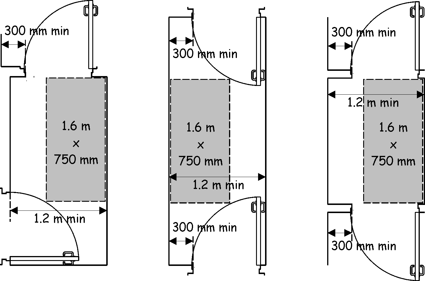
Where either door can be secured by a locking device, the lobby should be not less than 1.5m wide. This will permit a wheelchair or pram to be turned around should passage be denied.
However the above recommendations need not be applied to a lobby leading solely to sanitary accommodation which does not contain an enlarged WC cubicle or an accessible sanitary facility.
4.2.5 Internal doors
Within a building, doors should present as little restriction to passage as possible and be constructed in a manner that does not present a hazard or a potential barrier to access.
An internal door within a building should:
a.if fitted with a threshold, have an accessible threshold, and
b.have a door leaf which provides a clear opening width in accordance with the table below, and
c.if across a circulation route or in other specified locations, have a clear glazed panel in any openable leaf, as noted below, and
d.if not a powered door, have an unobstructed space next to the leading edge of the opening face of the door of at least 300mm, and
e.if fitted with a closing device, meet the recommendations given in clause 4.2.6.
Table 4.1. Width of doors
| Minimum corridor width at door (mm) | Minimum clear opening width (mm) [1] |
|---|---|
| 1500 | 800 |
| 1200 | 825 [2] |
| 900 [3] | 850 [2] |
Additional information:
1.The projection of any ironmongery that extends across the width of a door leaf, such as an emergency push bar to a fire exit or horizontal pull handle to accessible sanitary accommodation, should be subtracted when calculating the clear opening width.
2.The clear opening width may reduce to 800mm where a door is approached head-on.
3.A corridor width of less than 1.2m should not be present within new buildings but may be found within some existing buildings.
However the above provisions need not apply to a door within part of a building to which access by stair, ramp or lifting device need not be provided, as set out in clause 4.2.1. In addition, within sanitary accommodation, sub-clauses (b) & (d) need only apply to a door giving access to an enlarged WC cubicle or to an accessible sanitary facility.
A door should not open onto a corridor in a manner that might create an obstruction, other than a door to a cupboard or duct enclosure that is normally locked in a closed position.
A clear glazed vision panel, as described in clause 4.1.7, should be provided to any door across a corridor and:
•to a door between a circulation space and a room with an occupant capacity of more than 60, and
•to the outer door of a lobby leading solely to sanitary accommodation.
Vision panels may be omitted for security reasons, within places of lawful detention, or where light or noise control is essential, such as to a cinema or theatre auditorium, provided doors with a double swing action are not used.
4.2.6 Door closing devices
Heavy door leafs and strong closing devices can make an otherwise accessible door impassable to many building users. The force needed to open and pass through a door, against a closing device, therefore should be limited.
A door should be capable of operating with an opening force of not more than 30N (for first 30º of opening) and 22.5N (for remainder of swing) when measured at the leading edge of the leaf. Within this limit, a closing device should close the door leaf from any opening angle, against the resistance of any latch and seals, under normal operating conditions.
Where a door across a corridor requires to be retained in a closed position, in normal use or under fire conditions, and this cannot be achieved by use of a closer alone without exceeding these opening forces, a latch should be used to retain the door in a closed position and the door fitted with operating ironmongery.
A free swing device, which only has a closing action when activated by an alarm system, should not be fitted to a door across a circulation route as this permits the door to be left open at any angle, creating a collision hazard.
4.2.7 Vertical circulation between storeys
Stairs within a building should be designed to be accessible to a person with reduced mobility, as described in guidance to Standard 4.3. There should be an accessible stair between each level of a building.
In addition to such a stair, a means of unassisted access, other than a ramp, should be provided between storeys except to specific areas where access by a lift need not be provided, as described in clause 4.2.1.
Generally, unassisted access between storeys should be provided by a passenger lift, with the installation meeting the recommendations of BS EN 81-70: 2003.
In some circumstances, when altering existing buildings or within new buildings with a small storey area, it may not always be reasonably practicable to install a passenger lift. In such cases, where vertical travel is not more than 4.0m, the installation of a powered lifting platform meeting the recommendations of BS 6440: 1999, may be considered.
General provisions for lifting devices - any lifting device should be designed and installed to include the following general provisions:
•a clear landing at least 1.5m x 1.5m in front of any lift entrance door, and
•controls on each level served, between 900mm and 1.1m above the landing, and within the lift car on a side wall between 900mm and 1.1m above the car floor and at least 400mm from any corner, and
•on the landing of each level served, tactile call buttons and visual and tactile indication of the storey level, and
•lift doors, handrails and controls that contrast visually with surrounding surfaces, and
•a signalling system which gives notification that the lift is answering a call made from a landing, and
•a means of two way communication, operable by a person with a hearing impairment, that allows contact with the lift if an alarm is activated, together with visual indicators that alarm has been sounded and received.
In addition to general provisions for lifting devices, a passenger lift should be provided with:
•automatic lift door(s), with a clear opening width of at least 800mm, fitted with sensors that will prevent injury from contact with closing doors, and
•a lift car at least 1.1m wide by 1.4m deep, and
•within the overall dimensions of the lift car, a horizontal handrail, of a size and section that is easily gripped, located 900mm above the floor on any wall not containing a door, and
•within a lift car not offering through passage, a mirror on the wall facing the doors, above handrail height, to assist a wheelchair user in reversing out, and
•within the lift car, tactile storey selector buttons and, in a lift serving more than 2 storeys, visual and voice indicators of the storey reached, and
•a system which permits adjustment of the dwell time after which the lift doors close, once fully opened, to suit the level of use.
In addition to general provisions for lifting devices, a powered lifting platform should:
•if serving a storey to which the public have access, have a platform size of 1100mm wide by 1400mm deep and a clear opening width to any door of 850mm, or
•if serving any other storey, have a platform size of at least 1050mm wide by 1250mm deep and a clear opening width to any door of 800mm, and
•be fully contained within a liftway enclosure, and
•have a operational speed of not more than 0.15 metres per second, and
•be operated by a continuous pressure type control, of a form operable by a person with limited manual dexterity, and
•be provided with a horizontal handrail, of a size and section that is easily gripped, 900mm above the floor fitted to at least one side of the platform, and
•be provided with permanent and clear operating instructions located adjacent to or within the platform.
4.2.8 Vertical circulation within storeys
In addition to a stair, as described in guidance to Standard 4.3, a ramp or lifting device should be provided to every change of level within a storey, except to specific areas where access by a lift or ramp need not be provided, as described in clause 4.2.1.
Access between levels within a storey provided by a lifting device should be in accordance with the recommendation given in clause 4.2.7. However where a powered lifting platform is used, this may be without a liftway enclosure where vertical travel is not more than 2.0m.
4.2.9 Sleeping accommodation within residential buildings
Within residential buildings, such as hotels and halls of residence, sleeping accommodation which is accessible to a wheelchair user should be provided. At least 1 bedroom in 20, or part thereof, should:
•be provided with accessible sanitary accommodation, as noted in clause 3.12.3, and
•have an effective clear width of not less than 1.2m between walls, fixed furniture or other permanent obstructions within the room, and
•contain a manoeuvring space of at least 1.5m by 1.5m, clear of obstructions, including furniture and any door swing, and
•have a clear space around at least one bed of at least 700mm wide to the foot and one side and at least 1.5m wide to the other side, which may overlap with the manoeuvring space noted above, and
•include an assistance alarm that can be operated or reset from a bed space, and is also operable from floor level. The alarm should have an audible tone distinguishable from a fire alarm and a visual indicator provided both within and outside the bedroom and should also give alert at a location where staff will be on duty.
However in a place of lawful detention, the ratio may be increased to not more than 1 in 100.
4.2.10 Fixed counter installations at service points
Fixed counter installations such as a reception desk or a serving counter in a bar or restaurant should be accessible to a person who is standing, regardless of stature, or seated in a wheelchair.
To allow this, surfaces should be provided at two levels. For standing users, this should be within a range of 950mm to 1.1m in height. For seated users, this should be approximately 750mm above floor level, with a knee recess below of at least 500mm deep and at least 700mm high and a clear manoeuvring space in front of the surface of at least 1.2m deep. The knee recess is particularly important where activities such as writing may take place, such as at a bank counter. Where depth of the surface will permit, the knee recess should be provided to both sides of the counter.
Where only one such counter is proposed a portion of the surface, not less than 900mm wide or, where practical in larger installations, 1.5m wide, should be installed at lower height. Where a number of similar counters are proposed, at least one counter should be installed at the lower height.
4.3 Stairs and ramps
#Source page 74
Mandatory Standard
Standard 4.3
Every building must be designed and constructed in such a way that every level can be reached safely by stairs or ramps.
4.3.0 Introduction
Half of all accidents involving falls within and around buildings occur on stairways, with young children and elderly people being particularly at risk. This risk can be greatly reduced by ensuring that any change in level incorporates basic precautions to guard against accident and falls.
Stairs and ramps should be constructed to be within limits recognised as offering safe and convenient passage and designed so that any person who is likely to use them can do so comfortably and safely, with the minimum amount of difficulty. Design should also address the issue of appropriate guarding, where a level change is made, and seek to eliminate any possible trip hazards.
Explanation of terms
The following terms are explained to provide clarity to their meaning in the Technical Handbooks.
Tapered tread means a stair tread in which the nosing is not parallel to the nosing of the tread or landing next above.
Conversions - in the case of conversions, as specified in regulation 4, the building as converted shall meet the requirements of this standard in so far as is reasonably practicable, and in no case be worse than before the conversion (regulation 12, schedule 6).
4.3.1 Measurement for stairs
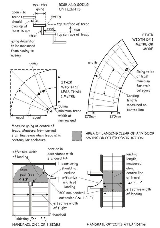
4.3.2 Rise, going, tread and pitch of stairs
The geometry of a stair flight can have a significant effect on the ability of people to use a stair safely and conveniently and limits should be placed on the rise and going of a stair, and steepness of pitch.
To provide safe and convenient access, the rise, going, tread and pitch of a flight in a stair should be in accordance with the following table:
Table 4.2. Stair geometry - stairs to or within a building
| Minimum rise (mm) | Maximum rise (mm) | Minimum going (mm) | Tread | Maximum pitch |
|---|---|---|---|---|
| 100 | 170 | 250 | not less than going | 34º |
Additional information:
1.All rises in a flight should be of uniform height.
2.In a straight flight, or in a part of a flight that is straight, measurement should be uniform along the centreline of the flight.
3.Where a flight consists partly of straight and partly of tapered treads, the going of the tapered treads should be uniform and should not be less than the going of the straight treads.
4.The going measured at the narrow end of a tapered tread should be at least 50mm (see diagram to clause 4.3.2).
5.The aggregate of the going and twice the rise should be at least 550mm and not more than 700mm. For example, stairs provided with the minimum going of 250mm would result in rises of at least 150mm.
6.In a stair, wholly within shared residential accommodation, maximum rise may be 220mm, minimum going may be 225mm and maximum pitch may be 42º.
The most comfortable combination of rise and going varies between individuals but in general, a going in excess of the minimum, resulting in a figure in the upper end of the range in note 5 above, will increase both safety and amenity.
4.3.3 Width of stair flights and landings
The clear, or effective, width of a stair should allow users to move up and down unhindered and permit people to pass on a flight.
The effective width should be measured between handrails or, where there is no handrail present, between any walls or protective barriers. It should be clear of obstructions, as described in the diagram to clause 4.3.2. The effective width of a stair should be not less than 1.0m, or otherwise in accordance with the recommendations of the following table:
Table 4.3. Effective widths of flights and landings
| Stair wholly within shared residential accommodation | Escape stairs | Any other stair |
|---|---|---|
| refer to recommendations in guidance to Standard 2.9 | not less than 1.0m |
Additional information:
1.The effective width of the stair within shared residential accommodation may be 800mm where a handrail is fitted to both sides of the flight.
The projection of any stringer or newel post into this width should be not more than 30mm.
4.3.4 Number of rises in a flight
The act of climbing stairs can be tiring to many people. Whilst landings can provide a safe resting point, the flight itself is not intended to do so. The maximum number of rises between landings should therefore be limited.
Generally, a flight should have not more than 16 rises.
Below a minimum number of steps, it becomes difficult to signal a change of level, which can contribute significantly to a trip hazard.
Generally, a flight should have at least 3 rises.
However people tend to take greater care at certain locations, such as at an external door, and a single step or 2 steps may be appropriate under certain circumstances. There may be less than 3 rises:
a.other than at an accessible entrance, between an external door of a building and the ground, or
b.between a landing and an adjoining level where the route of travel from the adjoining level to the next flight changes direction through 90º (i.e. a quarter landing).
4.3.5 Risers and treads
All stairs providing access to and within buildings should be designed to be accessible by most persons with reduced mobility.
Open risers on a flight can be a hazard. When ascending a stair, people may be at risk of trapping the toes of shoes beneath projecting nosings, and of tripping as a result. In addition, many may feel a sense of insecurity when looking through spaces present between treads.
A stair should have contrasting nosings to assist in identifying the position of treads and risers should be profiled to minimise tripping as shown below. Open rises should not be used unless a stair is intended for descent only, such as in a dedicated escape stair on an escape route.
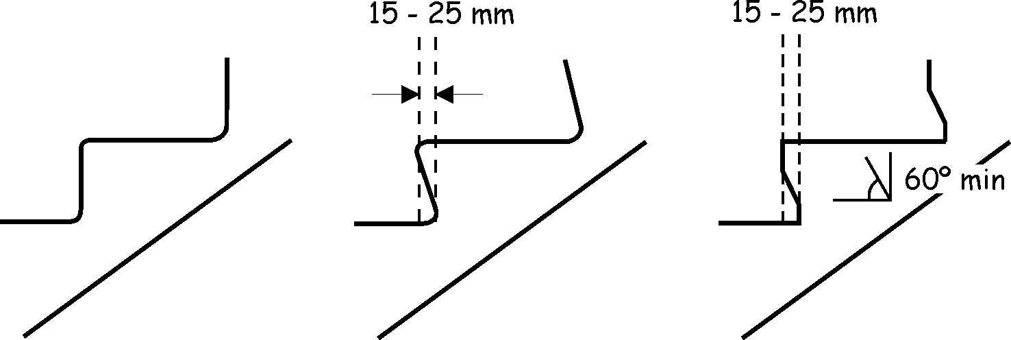
However a stair within shared residential accommodation may be constructed with open risers and without contrasting nosings as occupants will be more familiar with the stair through frequent use.
Small children can climb or fall through gaps in stair treads and the size of such gaps should be limited to prevent this. In a flight with open rises, the treads should overlap by at least 15mm. Any opening between adjacent treads in a flight should be small enough to prevent the passage of a 100mm sphere.
4.3.6 Stair landings
Clear space is needed to the head and foot of any stair flight to allow people to move between a flight and an adjacent level surface safely. People may also wish to pause on stairs, particularly during ascent, and any intermediate landing should provide a temporary respite and be of a size to allow this whilst still permitting others to pass safely.
A stair landing should:
•be provided at the top and bottom of every flight. A single landing may be common to 2 or more flights, and
•be level except, in external locations, for any minimal crossfall necessary to prevent standing water, and
•have an effective width of not less than the effective width of the stair flight it serves, and
•be clear of any door swing or other obstruction.
The minimum length of a stair landing, measured on the centreline of travel, should be either 1.2m or the effective width of the stair, whichever is less. However, where on an intermediate landing, a change of direction of 90º or more occurs, the centreline length need not be measured if the effective width of the stair is maintained across the landing.
On landings to external stair flights, where tactile paving is used, the minimum length of landing should be 1.2m.
A landing need not be provided to a flight of steps between the external door of a building and the ground where:
•the door is not an accessible entrance, and
•the door slides or opens in a direction away from the flight, and
•the rise of the flight is not more than 600mm.
4.3.7 Warning surfaces to landings of external steps
A sudden and unguarded change of level on an access route can present a hazard to a person with a visual impairment. Therefore, on external access routes, tactile paving should be used to alert people to the presence of a flight of steps.
The use of ‘corduroy’ tactile paving identifies this hazard and advises users to ‘proceed with caution’. It should be provided at the head and foot of any flight of external steps, forming a strip 800mm deep, positioned 400mm from the first step edge, as noted below.
On any landing mutual to a flight of steps and a ramp, tactile paving should lie outwith the landing area of any ramp flight, to prevent possible confusion which might lead to injury.
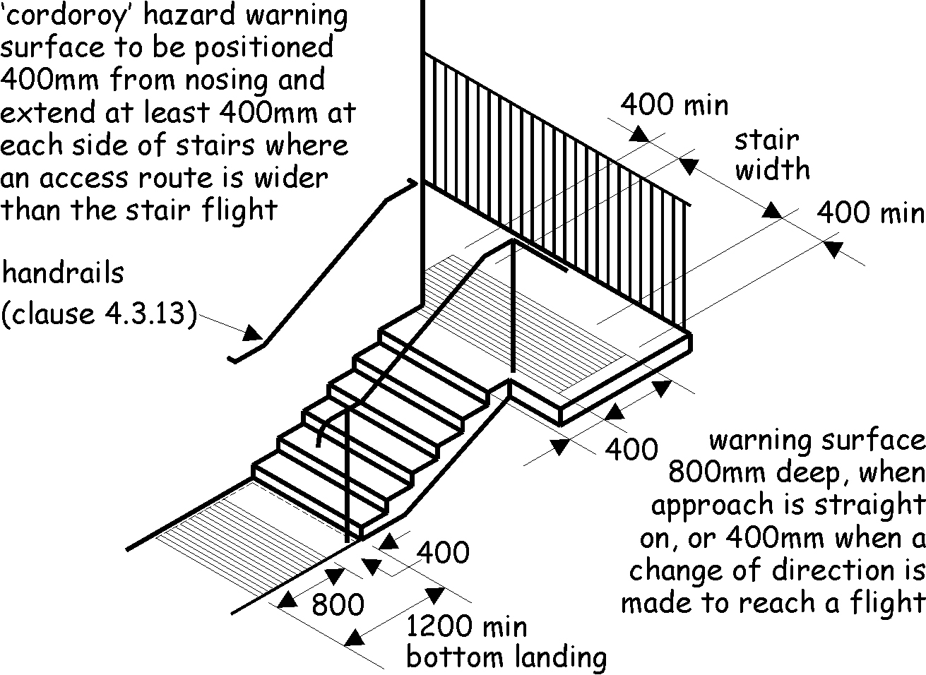
General information on use of tactile paving, including options on intermediate landings, is given in 'Guidance on the Use of Tactile Paving Surfaces'.
4.3.8 Stair flights consisting of both straight and tapered treads
On that part of a flight consisting of tapered treads, the going of the tapered treads should be uniform and should not be less than the going of the straight treads. At the inner end of the tread, the going should be at least 50mm. Tapered treads on a stair should be constructed in accordance with BS 585: Part 1: 1989, Appendices B1 and B3, irrespective of material or whether it contains open rises. However guarding should be in accordance with the guidance in clause 4.4.3.
In a flight less than 1m wide the going should be measured at the centre line of the flight as described in clause 4.3.1. In a flight 1m wide or more the going should be measured at 2 points, 270mm from each end of the tread, as described in clause 4.3.1 and the minimum going should be at least the going of the straight treads.
4.3.9 Stair flights consisting wholly of tapered treads
Stairs formed from tapering treads, particularly where forming a spiral, can present greater difficulties in use for many people than straight flights. There should be an appropriate level of safety and amenity on such stairs, particularly where used as a primary means of access.
A flight consisting wholly of tapered treads, forming a helix or spiral, should be constructed to give safe passage. To achieve this, it should be constructed in accordance with the guidance in BS 5395: Part 2: 1984, but account should be taken of the following guidance clauses:
•minimum and maximum rise should be as recommended in clause 4.3.2, and
•the effective width should be as recommended in clause 4.3.3, and
•the maximum number of rises on a flight should be as recommended in clause 4.3.4, and
•other than on a stair within shared residential accommodation, risers and treads should be as recommended in clause 4.3.5, and
•handrails should be as recommended in clauses 4.3.13 and 4.3.14, and
•protective barriers should be as recommended in clause 4.4.2.
4.3.10 Pedestrian ramps
Surfaces with a gradient of 1 in 20 to not more than 1 in 12 are considered to be ramps and recommendations are made on such surfaces to ensure the safety and amenity of users. Gradients of more than 1 in 12 are considered too steep to negotiate safely and are not recommended.
Steep gradients require both greater effort to ascend and more care when descending. As a general principle, the steeper the gradient of a ramp, the shorter the flight should be. A pedestrian ramp should be constructed in accordance with the following table:
Table 4.4. Gradient, length and rise of a flight in a pedestrian ramp
| Maximum gradient of flight | Maximum length of flight | Maximum rise |
|---|---|---|
| 1 in 20 | 10m | 500mm |
| 1 in 15 | 5m | 333mm |
| 1 in 12 | 2m | 166mm |
| More than 1 in 12 | Not recommended | Not recommended |
Additional information:
1.The maximum flight length for a particular gradient can be interpolated as follows: 3m long for a gradient of 1 in 13, 4m long for a gradient of 1 in 14, and so on.
4.3.11 Width of ramps flights
The width of a ramp should relate to the intensity of use. For example, an unobstructed width of 1.8m is the minimum that will allow two wheelchair users to pass safely. As a ramp flight will normally be enclosed between flanking handrails or guarding, it is important that this width still offers safe and convenient passage.
The effective width of a ramp flight should be at least 1.0m. Effective width is measured between handrails, or where there are no handrails, the protective barrier or inside face of any wall or guarding kerb, and should be clear of any obstructions.
A ramp which forms part of an escape route should have an effective width of not less than 1.2m and follow the general guidance for escape route corridors given in the guidance to Standard 2.9.
4.3.12 Ramp landings
Clear space is needed to the head and foot of any ramp flight to allow people to move between a flight and an adjacent level surface safely. This should permit manoeuvring of a wheelchair without obstructing passage or the need to encroach into circulation routes or onto a ramp flight.
A ramp landing should:
•be provided at the top and bottom of every flight. A single landing may be common to 2 or more flights, and
•be level except, in external locations, for any minimal crossfall necessary to prevent standing water, and
•have an effective width not less than the effective width of the flight it serves, and
•be clear of any door swing or other obstruction.
The unobstructed length of a landing should be not less than 1.5m, to allow space for wheelchairs or prams to stop after travelling down a flight and to provide manoeuvring space.
Where the entire length of a series of ramp flights is not visible from either the top or bottom landing, intermediate landings should have an effective width of not less than 1.8m, to provide passing places during ascent or descent.
4.3.13 Handrails to stairs and ramps
Handrails to stair and ramp flights will provide support and assist safe passage. As the full width of a flight may be used, either by people passing or by a person who favours one side, a handrail should generally be provided to both sides of a stair or ramp flight.
A handrail should be provided to both sides of any flight where there is a change of level of more than 600mm, or where the flight on a ramp is longer than 2m.
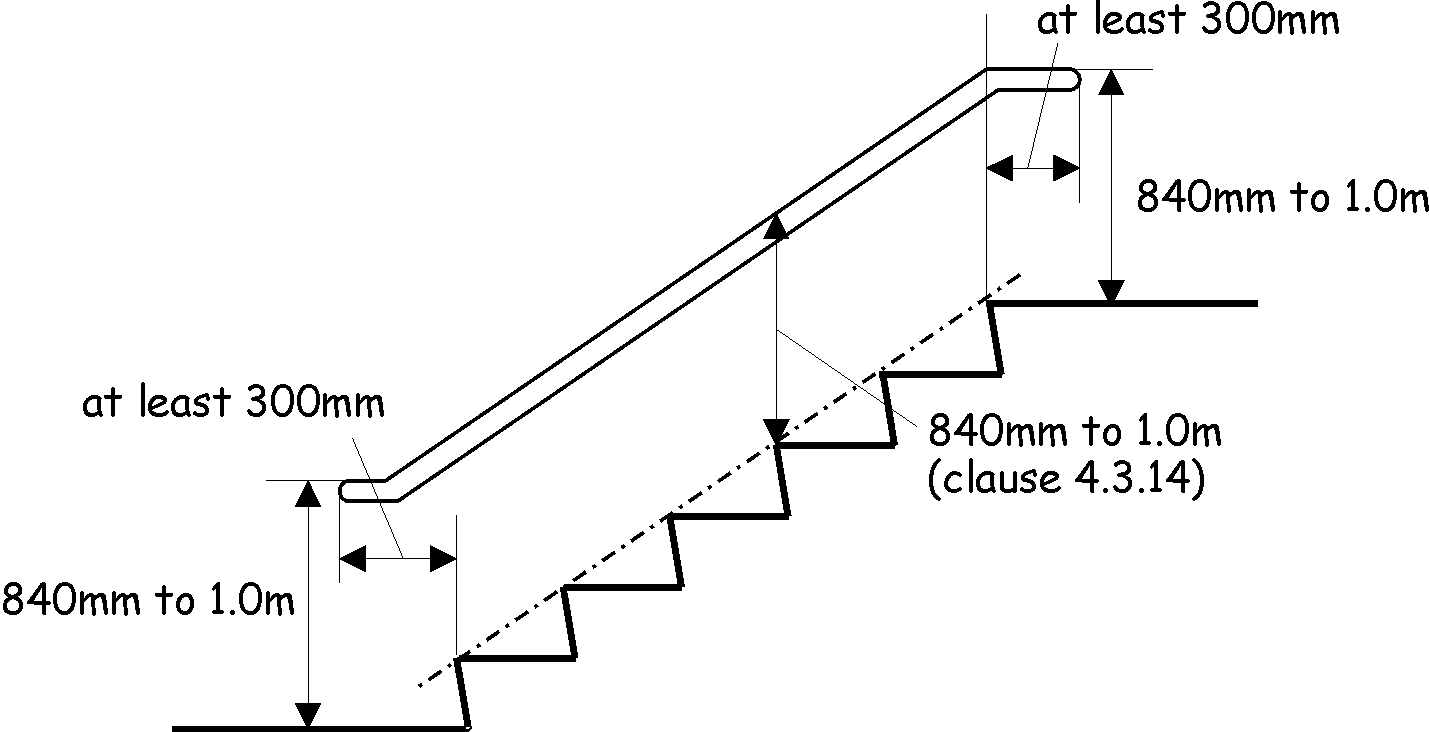
The extension of a handrail at landings allows an individual to steady themselves before ascending or descending. For a person with impaired vision, the change in slope of the handrail and its return into a wall can also signal the start or finish of a flight.
A handrail on a stair or ramp flight should:
a.extend at least 300mm beyond the top and bottom of the flight as shown in the diagram above. However the 300mm extension may be omitted where the handrail abuts a newel post, and
b.have a profile and projection that will allow a firm grip, and
c.end in a manner, such as a scrolled or wreathed end, that will not present a risk of entrapment to users, and
d.contrast visually with any adjacent wall surface.
A stair or ramp that is more than 2.3m wide should be divided by a handrail, or handrails, in such a way that each section is at least 1.1m and not more than 1.8m wide. This does not apply to a stair between an entrance door to a building and ground level, unless forming part of an escape route.
4.3.14 Height of handrails
A handrail should be fixed at a height of at least 840mm and not more than 1.0m, measured vertically above the pitch line of a flight on a stair or ramp and on a landing where a handrail is provided.
4.3.15 Headroom on stairs and ramps
A flight or landing on a stair or ramp should have clear headroom of at least 2.0m extending over the whole of the effective width. Height should be measured vertically from the pitch line of the flight or from the surface of the landing.
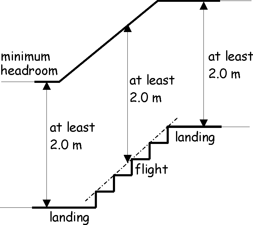
4.3.16 Industrial stairs and fixed ladders
An industrial stair or fixed ladder serving an area in any building to which only limited access is provided should be constructed so as to offer safe passage. This method of access is not for public use and would only be expected to be provided in places such as plant-rooms. A stair or ladder should be constructed in accordance with:
a.BS 5395: Part 3: 1985 or BS 4211: 2005, as appropriate, or
b.BS 5395: Part 2: 1984 where the stair is a spiral or helical stair.
4.3.17 Stairs and fixed ladders in agricultural buildings
A stair or fixed ladder in an agricultural building should offer safe passage. Such a stair or fixed ladder should be constructed in accordance with BS 5502: Part 80: 1990.
4.3.18 Stepped or ramped gangways within areas of fixed seating
In buildings designed for assembly and entertainment, where areas of fixed seating are provided to accommodate spectators, access is commonly provided by gangways separating areas of seating.
To maintain sight lines for spectators, it is common for seating areas to be formed on a rake, either as a continuous gradient or following a rising parabolic curve. In the latter, steps following the curve may be provided if the variation in step rises is uniform within a flight.
The design of radial gangways – those running ‘at right angles’ to seating rows – should allow safe access and minimise possible hazards to users.
Where a stepped or ramped gangway provides access within an area of fixed seating, it should be in accordance with the general guidance set out in this standard. However it is not necessary to provide:
a.a handrail where the edge of a stepped or ramped gangway is adjacent to fixed seating or an appropriate barrier. Where the side of a gangway is remote from seating, appropriate guarding should be provided as described in clauses 4.4.1 and 4.4.2
b.a landing in accordance with clause 4.3.6 at the foot of a stepped gangway where this gives direct access only to fixed seating, e.g. at a balcony, and where a protective barrier is provided as described in clauses 4.4.1 and 4.4.2.
Where fixed seating is installed, intermediate steps between tiers of seating should be positioned to minimise projection of any riser into the clearway zone at the end of each row. This may result in treads of differing lengths. A regular step rhythm should be maintained in all cases.
4.4 Pedestrian protective barriers
#Source page 75
Mandatory Standard
| Standard 4.4 Every building must be designed and constructed in such a way that every sudden change of level that is accessible in, or around, the building is guarded by the provision of pedestrian protective barriers. Limitation: This standard does not apply where the provision of pedestrian protective barriers would obstruct the use of areas so guarded. |
4.4.0 Introduction
Protective barriers are necessary to prevent people in and around buildings from an accidental fall at an unguarded change of level.
In assessing the type of barrier to be used, the likely hazards, the use of the building and the risks to the people that may be present should all be considered. Any barrier should minimise the risk of persons falling or slipping through gaps in the barrier.
Young children are often adept at climbing anything within their reach. It is important that the design of protective barriers restrict the ability of young children to climb them, thereby reducing the possibility of injury from falls.
Existing Buildings - it is acknowledged that some existing non-domestic buildings have protective barriers that were designed or constructed with gaps large enough that a child could pass through or that can be easily climbed. Those responsible for these buildings may wish to consider assessing the suitability of these barriers. Where children could be in the building the assessment should consider what risk reduction measures are required. Further information on the assessment of existing protective barriers is provided in the guidance leaflet 'Are Your Barriers Safe' which is available to view or download at www.scotland.gov.uk/bsd.
Conversions - in the case of conversions, as specified in regulation 4, the building as converted shall meet the requirements of this standard in so far as is reasonably practicable, and in no case be worse than before the conversion (regulation 12, schedule 6).
4.4.1 Location of pedestrian protective barriers
In the interests of safety, protective barriers should be provided where there is a sudden change in level and the possibility of severe injury from a fall.
At a change of direction on an access route, a drop of any height can be a hazard, particularly to a wheelchair user or a person with a visual impairment. A protective barrier should be provided both where a significant drop occurs and in locations where a smaller change of level may increase the risk of injury.
It is not practical to provide a barrier at every change in level, but a protective barrier for pedestrians should be provided at the edge of:
a.every floor, stair, ramp, landing, raised floor or other raised area to which people have access, where there is a difference in level of 600mm or more, and
b.any change in direction on an access or circulation route which is raised above the level of the surrounding surfaces.
However there is no need to provide a protective barrier in a location which would block an intended access route or be incompatible with the normal use of an area, such as to the edge of a loading bay or theatre stage.
A wall, partition or area of fixed glazing, constructed in accordance with the recommendations of clause 4.4.2, may act as an appropriate barrier.
To ensure a person can be aware of the presence of a protective barrier it should, unless forming part of a wall or partition, contrast visually with surrounding surfaces. If a barrier is principally glazed, the recommendations for marking given in clause 4.8.2 should be followed.
4.4.2 Design of pedestrian protective barriers
In and around non-domestic buildings gaps in any protective barrier should not be large enough to permit a child to pass through. To ensure this, openings in a protective barrier should prevent the passage of a 100mm diameter sphere.
A protective barrier should be designed and constructed so that it cannot be easily climbed by young children. The provision of potential hand and footholds should be minimised.
The likelihood of children being present should be accepted for all non-domestic buildings other than where their presence within the building, or part thereof, is precluded for valid reasons such as health and safety restrictions. In these buildings, where there are valid reasons for the preclusion of children, the above guidance on openings and potential hand and footholds within the protective barriers need not apply.
Typical examples of buildings where access for children may be precluded are within agricultural, industrial and warehouse buildings. Children may also only be precluded from specific parts of buildings, for example, where access is solely to or within a plant room forming part of an office building.
In all buildings, openings may be more than 100mm between a rise in a stair and the lowest edge of a protective barrier, provided the lowest edge of the barrier is not more than 50mm above, and parallel to the pitch line of the stair.
Historic Buildings - in certain cases, buildings may be of historic interest, listed (under planning legislation) or may be located in a conservation area. Alterations to these buildings may impact on the architecture or character of the building. In these circumstances, where a protective barrier has to be altered to protect children, it may be necessary to adopt a solution that is sympathetic to the character of the building. Guidance on this matter is contained within the 'Guide for practitioners 6 - Conversion of traditional buildings' issued by Historic Scotland.
A protective barrier, and any wall, partition or fixed glazing accepted instead of a barrier should be secure, capable of resisting loads calculated in accordance with BS EN 1991-1-1 and the associated PD 6688-1-1 and be a height as follows:
Table 4.5. Height of pedestrian protective barriers
| Location | Minimum height (mm) [1] |
|---|---|
| At the edge of a floor in front of walls, partitions and fixed glazing incapable of withstanding the loads specified in BS EN 1991-1-1/PD 6688-1-1 | 800 |
| In front of an openable window | 800 [2] |
| On a stair or ramp flight | 900 [3] |
| Directly in front of, or behind fixed seating | 800 [4] |
| All other locations | 1100 |
Additional information:
1.A handrail provided in accordance with clauses 4.3.13 and 4.3.14 may form the top of a protective barrier if the heights in this table are met.
2.Protective barriers should be installed where the opening window has: At 2 storeys or more above ground level, reference should be made to clause 4.8.4 where external glazing is cleanable from within the building.
3.Where a handrail forming the top of a protective barrier to a flight meets a protective barrier to a landing, the height of the latter may be reduced for a distance not more than 300mm to permit a smooth junction.
4.Barrier height may be reduced to 750mm where it has an overall width at the top of at least 250mm. At the foot of a gangway leading to fixed seating, the height of a protective barrier should be 1.1m.
4.4.3 Guarding to the edge of ramps
Where there is not a continuous pedestrian protective barrier to the edge of a ramp flight, a kerb upstand of at least 100mm high should be provided to any open side of the flight where there is a drop of any height. However the use of an upstand kerb alone in open landscaping is not recommended as it may present a potential trip hazard.
Alternatively, an external ramp flight may be provided with a landscaped margin, level with the edge or the ramp for a distance of 600mm before any grading.
4.5 Electrical safety
#Source page 76
Mandatory Standard
| Standard 4.5 Every building must be designed and constructed in such a way that the electrical installation does not: Limitation: This standard does not apply to an electrical installation: |
4.5.0 Introduction
The hazards posed by unsafe electrical installation are injuries caused by contact with electricity (shocks and burns) and injuries arising from fires in buildings ignited through malfunctioning or incorrect installations.
Concern has been expressed that risks have been increasing in recent years due to:
•the increasing prevalence and variety of electrical systems in buildings and the demands being made on them
•the reduction in subscription to voluntary industry self-regulation schemes.
The intention of this standard is to ensure that electrical installations are safe in terms of the hazards likely to arise from defective installations, namely fire, electric shock and burns or other personal injury. Installations should:
•safely accommodate any likely maximum demand, and
•incorporate appropriate automatic devices for protection against overcurrent or leakage, and
•provide means of isolating parts of the installation or equipment connected to it, as are necessary for safe working and maintenance.
The standard applies to fixed installations in buildings. An installation consists of the electrical wiring and associated components and fittings, including all permanently secured equipment, but excluding portable equipment and appliances.
Appendix 6 of BS 7671: 2008 (The Wiring Regulations) provides specimen certificates that may be completed by the person responsible for the installation. These can be issued to the person ordering the works as evidence of compliance with the recommendations of the British Standards.
‘Socket outlet’ means a fixed device containing contacts for the purpose of connecting to a supply of electricity the corresponding contacts of a plug attached to any current-using appliance.
Conversions - in the case of conversions, as specified in regulation 4, the building as converted shall meet the requirement of this standard (regulation 12, schedule 6).
4.5.1 Electrical installations
Electricity, when properly used, is a safe and convenient source of energy for heat, light and power within buildings. However misuse may lead to significant harm to individuals and buildings alike.
Risk of fire from an electrical installation should be minimised. In normal operation, taking into account the surroundings, it should not create the risk of fire, burns, shock or other injury to people.
An electrical installation should be designed, constructed, installed and tested such that it is in accordance with the recommendations of BS 7671: 2008.
Professional expertise - electrical installation work should be inspected and tested by persons who possess sufficient technical knowledge, relevant practical skills and experience for the nature of the electrical work undertaken.
An approved certifier of construction who has been assessed to have the professional skills and relevant experience, can certify compliance of an electrical installation (see clause 4.0.5).
4.5.2 Extra-low voltage installations
To avoid the risk of harm, any circuit which is designed to operate at or below extra-low voltage should be protected against both direct and indirect contact with any other circuit operating at higher than extra-low voltage.
Extra-low voltage is defined as not more than 50 volts alternating current or 120 volts direct current, measured between conductors or to earth. This might include installations for alarm or detection purposes, or for transmission of sound, vision, data or power.
Any such installation should be designed, constructed, installed and tested such that it is in accordance with the recommendations of BS 7671: 2008.
4.5.3 Installations operating above low voltage
To avoid the risk of harm, any circuit which is designed to operate at a voltage higher than low voltage should be provided with a cut-off switch for use in emergency in accordance with the recommendations of BS 7671: 2008.
Low voltage is defined as not more than 1000 volts alternating current or 1500 volts direct current, measured between conductors or not more than 600 volts alternating current or 900 volts direct current between conductors and earth.
A fireman’s switch, in a conspicuous position, should be provided to any circuit supplying exterior electrical installations or internal discharge lighting installations (including luminous tube signage) operating at a voltage exceeding low voltage.
4.6 Electrical fixtures
#Source page 77
Mandatory Standard
| Standard 4.6 Every building must be designed and constructed in such a way that electric lighting points and socket outlets are provided to ensure the health, safety and convenience of occupants and visitors. Limitation: This standard applies only to domestic buildings where a supply of electricity is available. |
4.6.0 Introduction
This standard does not apply to non-domestic buildings.
4.7 Aids to communication
#Source page 78
Mandatory Standard
| Standard 4.7 Every building must be designed and constructed in such a way that it is provided with aids to assist those with a hearing impairment. Limitation: This standard does not apply to domestic buildings. |
4.7.0 Introduction
There are many situations within a building, where a means of clear communication needs to be ensured.
A variety of hearing enhancement systems are commonly used within buildings including induction loops, infrared and radio transmission systems. The type of system and performance sought should be considered at an early stage in the design process.
Hearing enhancement systems are important in locations where an audience will normally be present, where intelligibility of a sound source can be compromised by distance or reverberation, in locations where a physical barrier exists between speaker and listener and where information will be sought.
Designers and building operators should also be aware of the benefits that the use of temporary and portable hearing enhancement solutions can offer to a wider range of situations, outwith those listed in guidance.
Conversions - in the case of conversions, as specified in regulation 4, the building as converted must meet the requirements of this standard (regulation 12, schedule 6).
4.7.1 Hearing enhancement systems
People with hearing loss should be able to access facilities in a building and to participate fully in activities such as conferences, meetings and entertainment.
To enable this, a hearing enhancement system or similar device to assist a person with hearing loss should form part of a building installation and be provided to:
a.any auditorium or other space, with fixed seating, where an audience or spectators will be present, and
b.any room with a floor area more than 60m2 that is intended to include uses such as meetings, lectures, classes or presentations, and
c.any location where a person is separated from a vendor or service provider by a physical barrier such as a glazed screen, and
d.the principal reception desk, public counter or information point in any building to which the public have access. In larger buildings, with multiple entrances, there may be a number of these in different locations.
The installation of such a system should enhance sound communicated to the user, whether received directly through a personal hearing aid, or through additional equipment supplied as part of the system. It should preserve the characteristics of the source whilst suppressing reverberation and extraneous noise and should not be affected by environmental interference such as from lighting or other electrical installations.
The presence and type of hearing enhancement system installed should be indicated with clear signage at the entrance to any such room or at a service point.
Types of system - three forms of hearing enhancement system are in common use:
•audio frequency induction loop systems can provide assistance to users of personal hearing aids incorporating an induction pick-up facility (T setting) without the need for additional equipment and are common in both counter and larger room situations. They may not be suitable where a signal must be contained within a designated area or privacy of communication is required or in areas where interfering magnetic fields may be present
•infra red systems are popular in auditorium applications, offering line-of-sight wireless communication, providing flexibility and, within a room, privacy of transmission. They are not readily affected by electrical interference, though do require the use of additional personal receiver units. They can, however be adversely affected by strong sunlight
•radio systems offer benefits similar to infra-red, with the added advantage that line-of-sight is not required. However they can potentially offer less privacy as signals may pass through obstructions such as walls and be picked up on other receiving equipment.
Location and anticipated use are key factors in determining the most appropriate system for a given situation. General advice on provision and installation of listening equipment and selection of systems is available on the Action on Hearing Loss website, formally the RNID http://www.actiononhearingloss.org.uk/.
4.8 Danger from accidents
#Source page 79
Mandatory Standard
| Standard 4.8 Every building must be designed and constructed in such a way that: Limitation: Standard 4.8(d) does not apply to domestic buildings. |
4.8.0 Introduction
This standard covers several unrelated safety issues that do not lend themselves to inclusion in other standards although glass and glazing do figure prominently.
Collision or entrapment accidents result in a significant numbers of deaths and injuries to people in and around buildings every year. The majority of these accidents occur during normal use and involve building features such as doors, windows and areas of fixed glazing, with the risk of injury increased where vulnerable glass is involved. Collisions with glazing are very common as it can, if transparent, be difficult to see and may create confusing lighting effects, presenting particular difficulties for a person with a visual or cognitive impairment.
Falls still result in deaths and serious injury to people while cleaning windows. Whether windows are cleaned professionally or by the building owner, provision should be made to permit glazing to be cleaned safely.
Where ventilation is provided by openable windows or rooflights, people may encounter difficulty and a hazard may arise in using these items where controls are poorly sited. Similarly, location of electrical sockets, switches and other controls can, if not considered, affect safe and convenient use.
Roof work continues to be an activity with a high accident rate. Almost 1 in 5 construction deaths occur in this sphere of work. Roof work therefore should be recognised as a high-risk activity and high safety standards should be actively promoted by all those who are involved. Casual roof access should be discouraged but where access is provided, such as for inspection and maintenance, this should ensure safe access, giving protection against falls. Use of fragile roof materials should be discouraged wherever possible.
Conversions - in the case of conversions, as specified in regulation 4, the building as converted shall meet the requirements of this standard in so far as is reasonably practicable, and in no case be worse than before the conversion (regulation 12, schedule 6).
4.8.1 Collision with projections
Fixtures that project into, or open onto any place to which people have access can be a hazard. Any element of a building capable of projecting into a circulation route or space should be positioned, secured or guarded so that it does not present a risk to building users.
The simple way to avoid risk is to ensure that obstructions do not encroach into such spaces. However where a building element does project into a circulation route or space, and any part of the obstruction is less than 2.0m above the ground, guarding should be provided to both highlight the hazard and prevent collision with the building element.
Guarding should be provided to:
•any moveable projection, such as a door leaf or window frame, that opens across a circulation route or into a circulation space, or
•any permanent projection of more than 100mm into a circulation route or space that begins at a height of more than 300mm above the ground, or the projection of which increases with height by more than 100mm, or
•any accessible area where headroom reduces to less than 2.0m, such as beneath a stair flight.
Guarding should comprise of a continuous horizontal rail, at a height of between 900mm and 1.1m above ground level and a solid element, such as kerb upstand or rail, positioned approximately 100mm above ground level, to assist in detection by a visually impaired person using a cane.
There should be visual contrast between guarding rails and surrounding surfaces. Consideration should be given to positioning of guarding to direct a person away from the hazard, further reducing the risk of a collision.
Additional guarding may be needed to prevent collision with, or entrapment by, a powered door leaf (see clause 4.1.8).
4.8.2 Collision with glazing
Glazing in certain locations is more vulnerable to human impact. Care should be taken in the selection of glazing at low level in screens, walls and partitions or in areas surrounding doors, particularly where glazed side panels may be mistaken for doors.
To reduce the risk of injuries from accidental human impact in these locations, designers should either:
•fit glazing of a type, thickness and pane size that will be resistant to impact, which either does not break or breaks safely, or
•provide protection in the form of guarding to vulnerable glazing.
Glazing should be designed to resist human impact as set out in BS 6262: Part 4: 2005, where all, or part, of a pane is:
•within 800mm of floor level, or
•part of a door leaf, or
•within 300mm of a door leaf and within 1.5m of floor level.
Glazing manifestation - large areas of transparent glazing, in fixed screens or partitions or where forming doors, can be difficult to identify and may be a particular hazard to a person with a visual impairment. Glazing in a building, positioned where accidental collision may be likely, should be made apparent by some form of manifestation (marking). Differences in the design of manifestation used can also assist in identifying the position of doors within a glazed screen.
Manifestation should be of a size and form that is immediately obvious. It should, as far as is reasonably practicable, contrast visually with backgrounds viewed through the glazing by a person approaching from either side. Forms might include broken or solid lines, patterns or logos and may be a continuous element or at appropriate horizontal intervals. Manifestation should be present within 2 height ranges, between 850mm and 1.0m, and between 1.4m and 1.6m above floor level. It should be permanent, e.g. screen printed or opaque etching or a durable applied material which is not easily removed.
In addition, any unframed glazed door which operates on a pivot action should have any exposed vertical edge highlighted to contrast visually with surroundings, to assist in identifying the door edge when opening or in an open position. This is particularly important on powered doors.
4.8.3 Cleaning of windows and rooflights
Falls account for most window cleaning accidents, and generally occur from loss of balance through over-extension of reach or due to breakage of part of the building fabric through improper use or access. It is therefore important that all transparent or translucent glazing should be designed so that it may be cleaned safely.
There is, however no need to provide for the safe cleaning of any glazed element that is opaque and does not allow the passage of light.
Any window or rooflight, all or part of which is more than 4m above the adjacent ground or internal floor level, should be constructed so that any external and internal glazed surfaces can be cleaned safely from:
a.inside the building in accordance with the recommendations of Clause 8 of BS 8213: Part 1: 2004, or
b.a loadbearing surface, such as a balcony or catwalk, large enough to prevent a person falling further, or
c.a window access system, such as a cradle or travelling ladder, mounted on the building, as described in Annex C3 of BS 8213: Part 1: 2004, or
d.a ladder sited on adjacent ground or from an adjacent loadbearing surface which has unobstructed space large enough to allow the safe use of a ladder and which will contain a person from falling further. However a ladder should not be used to access any external or internal glazed surface more than 9m above the surface on which the ladder is sited. General guidance on the safe use of ladders may be found in HSE information sheet MISC613 'Safety in window cleaning using portable ladders'.
Glazing within a roof access hatch, located within a roof space, need not be constructed so that it may be safely cleaned.
When cleaning a window from inside, a person should not have to sit or stand on a window sill or use other aids to reach the external face of a window. The criterion of safety is the ability to reach all points on the surface of the external glazing with only the arm projecting outside the line of the window whilst remaining standing on the floor.
Safe reach - ergonomic statistics on reach capabilities for the UK adult population are given in Annex A of BS 8213: Part 1: 2004. As reach may safely be increased to some degree by use of cleaning implements, it would still be considered reasonable to apply a safe limit to downward reach of 610mm and a safe limit to lateral and vertical reach as an arc with a radius of 850mm measured from a point not more than 1.3m above floor level.
Cleaning from a loadbearing surface - where the window is to be cleaned from a loadbearing surface noted in subclause (b) to this clause, there should be provided:
•a means of safe access, and
•a protective barrier not less than 1.1m high to any edge of the surface or access which is likely to be dangerous.
This method of cleaning is only appropriate where no part of the glazing is more than 4m above the loadbearing surface.
Alternative methods - where there is a need for safe cleaning of glazing, it may be appropriate to consider alternate methods of cleaning, in addition to those listed in the guidance, where an equivalent level of safety can be demonstrated.
4.8.4 Guarding of windows for cleaning
For openable windows on the ground and first floor of a building, or where the outside face of the glazing will not be cleaned from inside the building, no guarding need be provided for the purpose of cleaning glazing. However the general guidance for provision of protective barriers given in clause 4.4.2 should be followed.
At greater heights, 2 storeys or more above ground level, where it is intended to clean the outside face of the glazing from inside the building, the increased risk from a fall should be recognised and guarding provided to a height of at least 1.1m above floor level.
Where guarding is provided, it should be designed to conform to BS 6180: 2011. All guarding should be permanently fixed and should not be detachable to permit windows to open. Guarding should be designed so that it is not easily climbable by young children unless their presence of within the building is precluded.
Guarding to a window is not needed where the open window gives access to a fully guarded balcony.
4.8.5 Emergency stopping of escalators and passenger conveyors
Escalators and passenger conveyors should be provided with devices capable of being readily operated that, when activated, can bring the equipment to a controlled halt in such a way that passengers will be able to maintain their balance.
The location of the devices and the stopping of the equipment should meet the recommendations of BS EN 115: 1995.
4.8.6 Access to manual controls
The location of a manual control device can have a significant effect on both the ease of operation of the device and safety in use. Positions that are inaccessible present a greater risk of accident when bending or reaching. Any control that is intended for operation by the occupants of a building should be installed in position that allows safe and convenient use.
This guidance is applicable to manual controls to openable ventilators, including windows and rooflights and to controls and outlets of electrical fixtures located on a wall or other vertical surface. Unless incorporating a restrictor or other protective device for safety reasons, controls should be operable with one hand.
An openable window, rooflight or other ventilator, intended to be operable by building occupants to provide natural ventilation, should have controls for opening, positioned at least 350mm from any internal corner, projecting wall or similar obstruction and at a height of:
•not more than 1.7m above floor level, where access to controls is unobstructed, and
•not more than 1.5m above floor level, where access to controls is limited by a fixed obstruction, not more than 900mm high which projects not more than 600mm in front of the position of the controls. Where obstruction is greater, a remote means of opening, in an unobstructed location, should be provided, and
•not more than 1.0m above floor level, in an unobstructed location, in any room intended specifically for use by a wheelchair user, such as an accessible bedroom.
The above guidance does not apply to windows or rooflights openable only for cleaning or maintenance purposes or that are controlled by an automatic system, or to trickle ventilators.
Outlets and controls of electrical fixtures and systems should be positioned at least 350mm from any internal corner, projecting wall or similar obstruction and, unless the need for a higher location can be demonstrated, not more than 1.2m above floor level. This would include fixtures such as sockets, switches, fire alarm call points and timer controls or programmers. Within this height range:
•light switches should be positioned at a height of between 900mm and 1.1m above floor level
•standard switched or unswitched socket outlets and outlets for other services such as telephone or television should be positioned at least 400mm above floor level. Above an obstruction, such as a worktop, fixtures should be at least 150mm above the projecting surface
•in accommodation specifically intended for wheelchair users, such as accessible bedrooms, operable controls should be located at a height of not more than 1.0m above floor level.
Where sockets are concealed, such as to the rear of built-in appliances, or obstructed by built-in furniture, separate switching should be provided in an accessible position, to allow appliances to be isolated.
4.8.7 Roof access
Working on roofs can be dangerous. Falls account for more deaths and serious injuries in the construction industry that any other cause. Any fall from a roof inevitably involves, at least, serious injury - the risks are substantial.
A means of safe and secure access should be provided to a roof of a building. One method of providing such access would be the installation of a stair, ladder or walkway meeting BS 5395: Part 3: 1985.
Access as described above need not be provided to a roof having eaves that, at any part, are at a height of less than 4.5m above the adjacent ground.
Alternative access - where access may occur on a very infrequent basis, it may not be appropriate to provide permanent access. In such cases, alternative access options might include a mobile platform or zip-up scaffolding in accordance with the guidance in HSE publications.
Unauthorised access - where fixed ladders are provided and could be accessible to the public, it would be appropriate to make the lowest section of the ladder (up to 4.5m) demountable to prevent unauthorised access.
4.8.8 Working on roofs
Where access to roofs is provided, precautions should be taken to limit the hazards presented by fragile roof surfaces.
There should be a clear visible warning identifying any part of a roof that is not capable of bearing a concentrated load of 0.9 kN on a 130mm by 130mm square. The visible warning should include the relevant hazard sign from BS 5499: Part 5: 2002.
4.9 Danger from heat
#Source page 80
Mandatory Standard
| Standard 4.9 Every building must be designed and constructed in such a way that protection is provided for people in, and around, the building from the danger of severe burns or scalds from the discharge of steam or hot water. |
4.9.0 Introduction
Guidance is given under this standard on a number of issues relating to hot water safety.
Guidance is given to minimise the risk of explosion due to malfunction of an unvented hot water vessel by:
•ensuring that such installations are carried out by appropriately qualified personnel, and
•requiring a minimum range of safety devices be fitted to any such installation to prevent the temperature of the stored water exceeding 100°C.
It is not intended that this guidance should be applied to storage systems with a capacity of less than 15 litres, to systems used solely for space heating or to any system used for an industrial or commercial process.
Hot water overflows - guidance is given on provisions for the safe removal of the discharge created by the normal operation of safety devices in such an installation to a safe and visible location.
Sanitary facilities - measures to prevent scalding from hot water are now addressed for certain sanitary facilities used for personal hygiene. Provisions and specific temperature limits, additional to recommendations in this guidance, may be applicable to certain building types or uses under other legislation, particularly through duties under Health and Safety legislation.
Maintaining safety devices - safety devices installed to protect from hazards such as scalding or the risk of explosion of unvented systems should be maintained to ensure correct operation. This forms part of an operator’s duty of care under Health and Safety legislation. Guidance on maintenance can be provided by both manufacturers and installers of such devices.
Conversions - in the case of conversions, as specified in regulation 4, the building as converted shall meet the requirement of this standard (regulation 12, schedule 6).
4.9.1 Installation of unvented hot water storage systems
Installation of an unvented hot water storage system should be carried out by a person with appropriate training and practical experience.
Competence of installers - this might include current membership of a registration scheme operated by a recognised professional body. This could include those administered by the Scottish and Northern Ireland Plumbing Employers Federation (SNIPEF) and the Construction Industry Training Board (CITB) or an equivalent body.
The following points should be noted in relation to installation of an unvented hot water storage system:
•the installer should be a competent person and, on completion, the labelling of the installation should identify the installer
•the installed system should meet the recommendations of BS 7206: 1990 or be the subject of an approval by a notified body and incorporate the safety devices outlined in clause 4.9.2
•certification of the unit or package should be recorded by permanent marking and a warning label which should be visible after installation. A comprehensive installation/user manual should be supplied
•the tundish and discharge pipework should be correctly located and fitted by the installer and the final discharge point should be visible and safely positioned where there is no risk from hot water discharge.
The operation of the system under discharge conditions should be tested to ensure provision is adequate.
4.9.2 Specification of small unvented hot water storage systems
An unvented hot water storage system should be designed and installed to prevent the temperature of the stored water at any time exceeding 100ºC and to provide protection from malfunctions of the system.
An unvented hot water storage system should be in the form of a proprietary unit or package which is in accordance with the recommendations of a relevant standard such as BS 12897: 2006, BS 6700: 2009 as appropriate or the subject of approval by a notified body to an equivalent level of safety and performance.
Pressure controls for a unit or package could include:
•a check valve to prevent backflow, and
•a pressure control valve to suit the operating pressure of the system, and
•an expansion valve to relieve excess pressure, and
•an external expansion vessel or other means of accommodating expanded heated water.
These devices are generally factory-fitted (unit) or supplied for fitting by the installer (package).
Independent safety devices - unit or package should have a minimum of 2 independent safety devices. An acceptable approach could be:
•a non self-resetting thermal cut-out, and
•a temperature relief valve or pressure relief valve (or combined temperature pressure relief valves).
These devices should be in additional to any thermostatic control that is fitted to maintain the temperature of the stored water at around 60ºC.
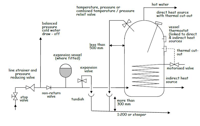
Thermal cut-out - a temperature-operated, non self-resetting, energy cut-out should be fitted to the vessel. In the event of thermostat failure, heating to the water in the vessel should stop before the temperature rises to the critical level required for operation of the temperature relief valve.
In indirectly heated vessels, the non self-resetting thermal cut-out should operate a motorised valve, or other similar device, to shut off the flow from the heat source.
On directly heated vessels or where an indirectly heated vessel has an alternative direct method of water heating fitted, a non self-resetting thermal cut-out device should be provided for each direct source.
The safety relief valve should be located directly on the storage vessel. The relief valve should conform to the relevant national standards such as BS 6283 Part 2: 1991 for temperature relief valves or BS EN 1490: 2000 for combined temperature and pressure relief valves which are set to open at temperatures not normally exceeding 90ºC.
The relief valve should have a discharge capacity rating at least equal to the rate of energy (power in kilowatts) input to the heat source. In the case of an indirectly heated unit or package, the valve should be tested to discharge water at a rate not less than 500kg/h for systems up to 45kW. The discharge pipework should accommodate this flow rate.
4.9.3 Specification of large unvented hot water storage systems
An unvented hot water storage system should be designed and installed to prevent the temperature of the stored water at any time exceeding 100ºC and to provide protection from malfunctions of the system.
Installations of this size will generally be specified to individual designs rather than supplied as proprietary units. The provision of evidence of compliance with safety requirements equivalent to the level set out in clause 4.9.2 should be the responsibility of the designer of the system.
Where the system has a power input of less than 45kW, safety devices should be provided in accordance with the recommendations of a relevant standard such as BS EN 12897:2006 or BS 6700:2009 as appropriate.
Where the system has a power input greater than 45kW, safety devices should include an appropriate number of temperature or combined temperature/pressure relief valves:
•to BS 6283: Part 2: 1991 or BS EN 1490: 2000, or
•of equivalent suitability marked with the activation temperature (in ºC), pressure (if relevant) and the discharge rating (in kW), measured in accordance with Appendix F of BS 6283 Part 2: 1991 or BS EN 1490: 2000.
Relief valves should provide a combined discharge rating at least equal to the power input of the system.
Provision of thermal cut-outs appropriate to the installation heat source(s) should be provided as noted in clause 4.9.2.
Discharge pipework should be provided as noted in clause 4.9.4, noting that the size of piping should be designed to accommodate the required discharge capacity and may exceed the guidance given in the table to clause 4.9.4.
4.9.4 Discharge from unvented hot water storage systems
The removal of discharges of water from the system can be considered in three parts.
Relief valve to tundish - each valve should discharge into a metal pipe not less than the nominal outlet size of the valve. The discharge pipe should have an air-break, such as a tundish, not more than 500mm from the vessel relief valve and located in an easily visible location within the same enclosure. Discharge pipes from more than one relief valve may be taken through the same tundish.
Pipework should be installed so that any discharge will be directed away from electrical components should the discharge outlet become blocked.
Tundish to final discharge point - the presence of this air break results in the pressure of the final discharge being no higher than that of a vented system.
The discharge pipe from the tundish to final discharge point should be of a material, usually copper, capable of withstanding water temperatures of up to 95ºC and be at least one pipe size larger than the outlet pipe to the relief valve.
A vertical section of pipe, at least 300mm long, should be provided beneath the tundish before any bends to the discharge pipe; thereafter the pipe should be appropriately supported to maintain a continuous fall of at least 1 in 200 to the discharge point.
The pipework should have a resistance to the flow of water no greater than that of a straight pipe 9m long unless the pipe bore is increased accordingly. Guidance on sizing of pipework from the tundish to the final discharge point is shown in the following table:
Table 4.6. Size of discharge pipework
| Valve outlet size | Minimum size of discharge pipe to tundish | Minimum size of discharge pipe from tundish | Maximum resistance allowed, expressed as a length of straight pipe i.e. no elbows or bends | Equivalent resistance created by the addition of each elbow or bend |
|---|---|---|---|---|
| G ½ | 15mm | 22mm 28mm 35mm | Up to 9m Up to 18m Up to 27m | 0.8m 1.0m 1.4m |
| G ¾ | 22mm | 28mm 35mm 42mm | Up to 9m Up to 18m Up to 27m | 1.0m 1.4m 1.7m |
| G 1 | 28mm | 35mm 42mm 54mm | Up to 9m Up to 18m Up to 27m | 1.4m 1.7m 2.3m |
Annex D to BS 6700: 1997 "Specification for design, installation, testing and maintenance of services supplying water for domestic use within buildings and their curtilages” also gives guidance on pipe sizing for water distribution systems.
Discharge pipe termination
The pipe termination should be in a visible location and installed so that discharge will not endanger anyone inside or outside the building.
Ideally, the final discharge point should be above the water seal to an external gully and below a fixed grating. Other methods for terminating the final discharge point would include:
a.up to 100mm above external surfaces such as car parks, grassed areas, or hard standings; a wire cage or similar guard should be provided to both prevent contact with discharge and protect the outlet from damage, whilst maintaining visibility
b.at high level into a hopper and downpipe of a material, such as cast iron, appropriate for a hot water discharge with the end of the discharge pipe clearly visible
c.onto a flat roof or pitched roof clad in a material capable of withstanding high temperature discharges of water, such as slate/clay/concrete tiles or metal sheet, with the discharge point a minimum of 3m from any plastic guttering system that would collect such discharges.
Discharge at high level may be possible if the discharge outlet is terminated in such a way as to direct the flow of water against the external face of a wall. However evidence of the minimum height of the outlet above any surface to which people have access and the distance needed to reduce the discharge to a non-scalding level should be established by test or otherwise.
4.9.5 Hot water discharge from sanitary fittings
Guidance to the Water Byelaws recommends that, to prevent the development of Legionella or similar pathogens, hot water within a storage vessel should be stored at a temperature of not less than 60ºC and distributed at a temperature of not less than 55ºC. Detailed guidance on the control of Legionella may be found in HSE Approved Code of Practice L8 – ‘Legionnaires’ Disease – Control of Legionella Bacteria in Water Systems’.
If water is supplied at high temperature from any source, there is a danger of scalding to building users. Risk of severe injury increases proportionally with increase in temperature and with extent of contact.
Facilities used for personal hygiene - to prevent scalding, the temperature of hot water, at point of delivery to a bath, shower or bidet, should be limited.
A device or system limiting water temperature should not compromise the principal means of providing protection from the risk of Legionella. It should allow flexibility in setting of a delivery temperature, up to a maximum of 48ºC, in a form that is not easily altered by building users.
Delivery temperature of hot water to a facility should relate to the vulnerability of people who may use the facility, particularly elderly people or unsupervised children, who are more at risk from injury. Reference should be made to existing recommendations on duty of care and risk assessment made under Health and Safety legislation and, in addition, to the following guidance available for specific building types:
•for residential care buildings, to recommendations in HSE publication HSG220 - ‘Health & Safety in Care Homes’
•for healthcare buildings, to recommendations in NHS Scotland Scottish Health Guidance Note ‘Safe Hot Water and Surface Temperatures’
•for schools, public buildings and buildings open to the public, to recommendations in 'Guidance to the Water Byelaws’, issued by Defra.
Where both hot and cold water are supplied to a facility, the above may be achieved, for single or limited outlet applications, by use of a thermostatic mixing valve (TMV) or fitting complying with BS EN 1111: 1999 or BS EN 1287: 1999, fitted as close to the point of delivery as practicable. Guidance on the installation, use and maintenance of thermostatic mixing valves and fittings for domestic-scale applications may be found in BRE information Paper IP 14/03 or from the Thermostatic Mixing Valve Association (TMVA).
4.10 Fixed seating
#Source page 81
Mandatory Standard
| Standard 4.10 Every building, which contains fixed seating accommodation for an audience or spectators, must be designed and constructed in such a way that a number of level spaces for wheelchairs are provided proportionate to the potential audience or spectators. Limitation: This standard does not apply to domestic buildings. |
4.10.0 Introduction
All people should have access to, and use of, facilities provided within buildings and should be able to participate in the proceedings at lecture/conference facilities and at entertainment or leisure and social venues.
The provision of flexible seating solutions, including spaces assigned for occupation by wheelchair users, will offer a greater level of general amenity. Consideration of a range of seat types and aisle widths, as well as the presence of removable seating will also offer greater choice for those using such facilities.
Conversions - in the case of conversions, as specified in regulation 4, the building as converted shall meet the requirements of this standard in so far as is reasonably practicable, and in no case be worse than before the conversions (regulation 12, schedule 6).
4.10.1 Variety in provision of fixed seating
Within any area of fixed seating, such as in a lecture room or auditorium or at a sporting venue, the layout should identify space for the seating of wheelchair users. These provisions may also benefit a person with mobility impairment or who may travel with an assistance dog.
Where arm rests are provided, seats at the end of a row or adjacent to a wheelchair space should have a removable or lift-up arm rest, to offer easier access to a proportion of seating.
A choice in seating location for wheelchair users should be available. Spaces should not be provided as a single area but dispersed through the seated area, as single spaces or pairs. Spaces should be next to standard seating to allow a spectator who uses a wheelchair to sit with family or friends.
In a level or raked auditorium, accessible spaces should be provided in a variety of locations. In a stepped auditorium, distribution of accessible spaces should be made on any level to which there is level or ramped access for the audience from another part of the building. The number of spaces should be in accordance with the following table:
Table 4.7. Wheelchair spaces to areas of fixed seating
| Seated capacity | Number of wheelchair spaces |
|---|---|
| up to 600 | 1 per 100 or part thereof [1] |
| 601 – 10 000 | 1 per 100 or part thereof |
| 10 001 – 20 000 | 100 + 5 per 1 000 above 10 000 |
| 20 001 – 40 000 | 150 + 3 per 1 000 above 20 000 |
| more than 40 000 | 210 + 2 per 1 000 above 40 000 |
Additional information:
1.In smaller auditoria, the presence of removable seating will offer increased flexibility and should be provided in addition to permanent wheelchair spaces. For each space noted above, removable seating providing one additional space should be present, up to a maximum of 6 spaces in total. For example, a 150 seat auditorium will have 2 wheelchair spaces and removable seating for a further 2 spaces.
Spaces should be level and not less than 1.4m long by 900mm wide, with an adjacent access width of at least 900mm. Within a raked or stepped auditorium, spaces should be provided with guarding to any edge where there is a change of level. Guarding, as recommended in clause 4.4.2, should include a rail or upstand to 100mm above floor level.
Spaces should be designed so that they neither obstruct nor are obstructed by other spectators and sight lines to any performance area or stage are maintained. This should take into account the potential obstruction from both a standing and seated audience.
4.11 Liquefied petroleum gas storage
#Source page 82
Mandatory Standard
| Standard 4.11 Every building must be designed and constructed in such a way that each liquefied petroleum gas storage installation, used solely to serve a combustion appliance providing space heating, water heating, or cooking facilities, will: Limitation: This standard does not apply to a liquefied petroleum gas storage container, or containers, for use with portable appliances. |
4.11.0 Introduction
This guidance deals with non-domestic supply installations where liquefied petroleum gas (LPG) is stored under pressure at ambient temperatures in fixed vessels larger than 75kg LPG capacity.
Guidance is also given on the storage of LPG within grouped cylinders, when connected to a supply installation.
The intention of the guidance to this standard is to minimise both the risk of fire spreading to the tank and of the contents of the tank forming explosive gas pockets in the vicinity of any LPG storage container.
All persons concerned with the storage and use of LPG should be aware of the following characteristics and potential hazards:
•the two forms of liquefied petroleum gases that are generally available in the UK are commercial butane and commercial propane
•LPG is stored as a liquid under pressure. It is colourless and its weight as a liquid is approximately half that of the equivalent volume of water
•LPG vapour is denser than air, commercial butane being about twice as heavy as air. Therefore the vapour may flow along the ground and into drains, sinking to the lowest level of the surroundings and may therefore be ignited at a considerable distance from the source of the leakage. In still air, vapour will disperse slowly
•when mixed with air, LPG can form a flammable mixture
•leakage of small quantities of the liquefied gas can give rise to large volumes of vapour/air mixture and thus cause considerable hazard
•owing to its rapid vaporisation and consequent lowering of temperature, LPG, particularly in liquid form, can cause severe frost burns if brought into contact with the skin
•a container that has held LPG and is ‘empty’ may still contain LPG in vapour form and is thus potentially dangerous.
Conversions - in the case of conversions, as specified in regulation 4, the building as converted shall meet the requirement of this standard (regulation 12, schedule 6).
4.11.1 LPG storage installations
The type, size and location of an LPG storage installation will determine the factors that should be addressed in the construction of the facility, to comply with health and safety requirements.
The UKLPG produces and maintains Codes of Practice which give guidance on achieving levels of risk appropriate to compliance with health and safety legislation for the design, construction and operation of LPG installations. These Codes have been produced in consultation with the Health and Safety Executive (HSE) http://www.hse.gov.uk/.
The operation of properties where LPG is stored or is in use are subject to legislation enforced by both the HSE and by the Local Authority.
4.11.2 LPG storage – fixed tanks
A liquefied petroleum gas storage tank, together with any associated pipework connecting the system to a combustion appliance providing space or water heating, or cooking facilities, should be designed, constructed and installed in accordance with the requirements set out in the UKLPG Code of Practice 1: 'Bulk LPG Storage at Fixed Installations'.
Above-ground tanks should be in accordance with Part 1 – ‘Design, Installation and Operation of Vessels Located Above Ground’, as amended.
Below-ground tanks should be in accordance with Part 4 – ‘Buried/Mounded LPG Storage Vessels’, as amended.
For propane installations, above or below-ground, of not more than 2 tonnes (4500 litres) overall capacity, reference may be made to the simplified guidance given in the UKLPG Code of Practice 1: ‘Bulk LPG Storage at Fixed Installations’: Part 2 – ‘Small Bulk Propane Installations for Domestic and Similar Purposes’, as amended.
Guidance given in this clause is relevant for all tanks, though specific criteria are noted for tanks below 4 tonnes LPG capacity (9000 litres). For guidance for larger installations, in excess of 4 tonnes LPG capacity, reference should be made to the relevant Part of the Code of Practice.
Every tank should be separated from a building, boundary, or fixed source of ignition, to:
a.in the event of fire, reduce the risk of fire spreading to the tank, and
b.enable safe dispersal in the event of venting or leaks.
Tanks should be situated outdoors, in a position that will not allow accumulation of vapour at ground level. Ground features such as open drains, manholes, gullies and cellar hatches, within the separation distances given in column (A) of the table overleaf should be sealed or trapped to prevent the passage of LPG vapour.
Tanks should be separated from buildings, boundaries or fixed sources of ignition in accordance with the table overleaf:
Table 4.8. Separation distances for liquefied petroleum gas storage tanks
| Maximum capacity (in tonnes) | Minimum separation distance for above ground tanks (in metres) | |||
|---|---|---|---|---|
| of any single tank | of any group of tanks | From a building, boundary or fixed source of ignition to the tank | between tanks | |
| A - no fire wall [1] | B - with fire wall [1] | |||
| 0.25 | 0.8 | 2.5 | 0.3 [2] | 1.0 |
| 1.1 | 3.5 | 3.0 | 1.5 [2] | 1.0 |
| 4.0 | 12.5 | 7.5 | 4.0 | 1.0 |
Additional information:
1.Fire wall means a wall or screen meeting the guidance for an external wall with a fire resistance of short duration (Section 2, Fire) within 1m of the boundary, and located between 1m and 1.5m from the tank and extending:
2.For vessels up to 1.1 tonnes capacity, the fire wall need be no higher than the top of the pressure relief valve and may form part of the site boundary. For vessels up to 1.1 tonnes capacity located closer to a building than the separation distance in column (A) of the above table, the fire wall should form part of the wall of the building in accordance with the diagram below. Where part of the building is used for residential accommodation (or as a dwelling), such a fire wall should meet the guidance for an external wall with a fire resistance of medium duration (Section 2, Fire).
Where a group of tanks are sited together, the number of tanks in a group should not exceed 6 and the total storage capacity of the group should not be more than that given for any group of tanks in the table above.
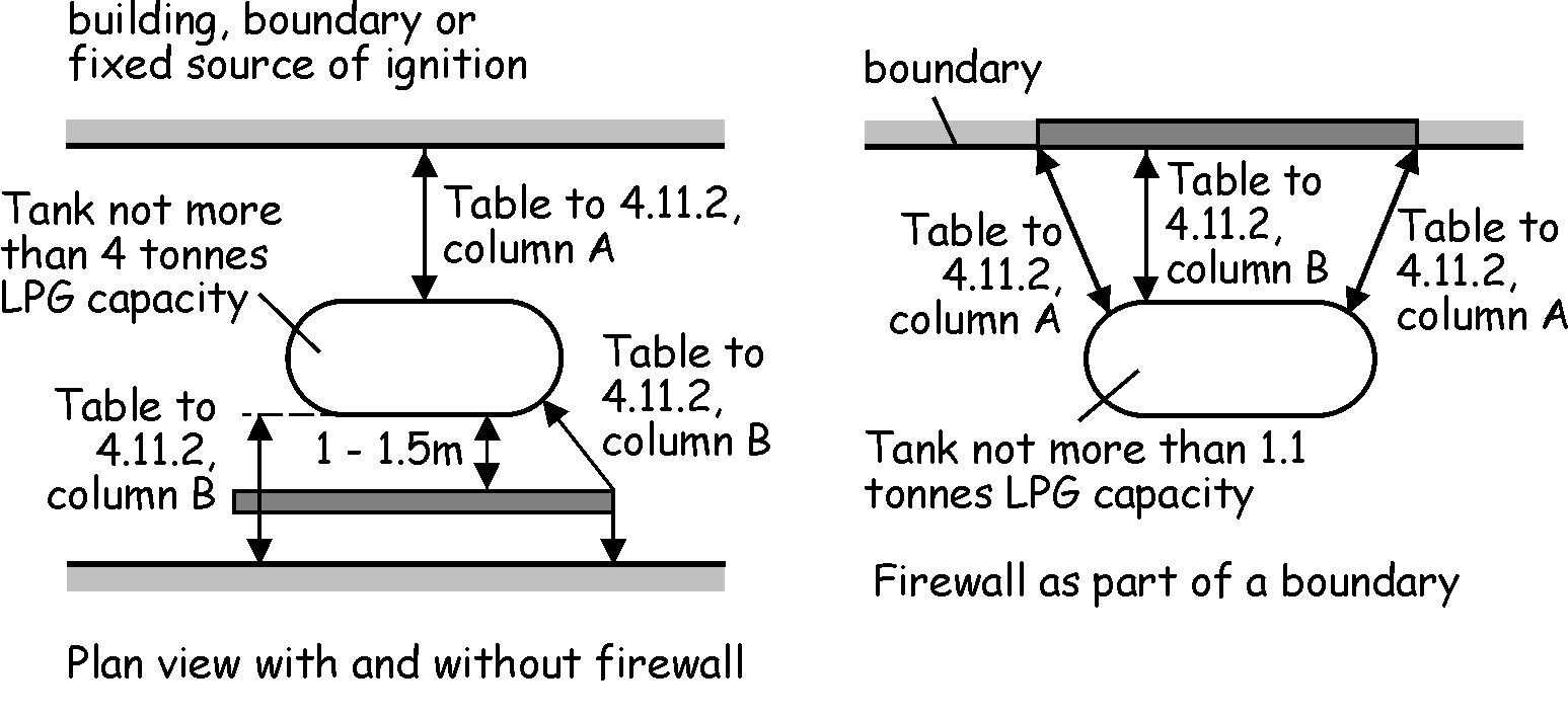
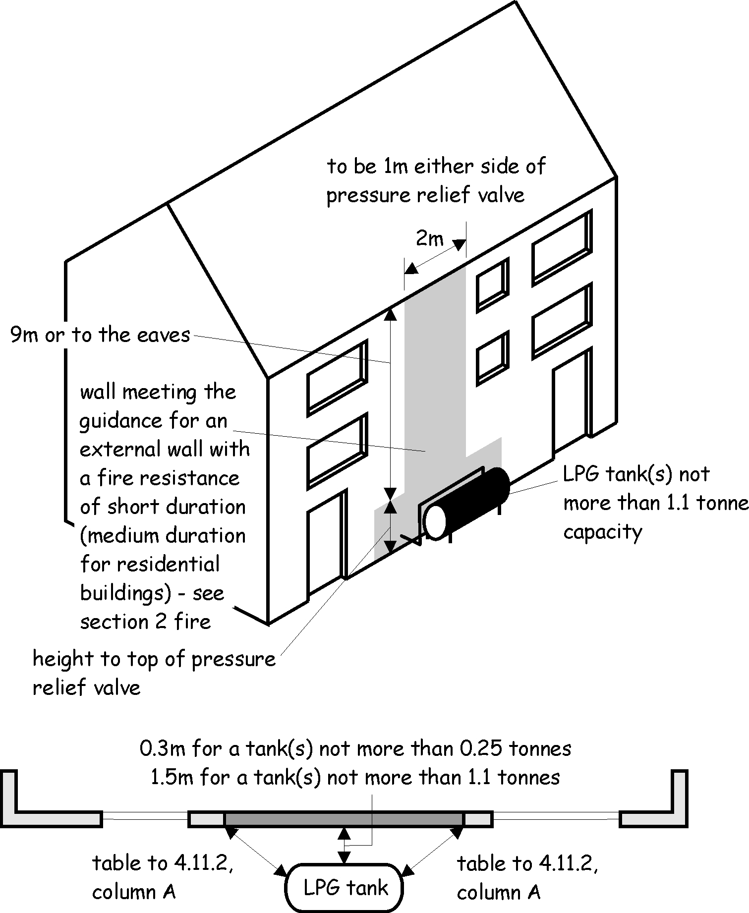
Vehicular parking areas - motor vehicles under the control of a site occupier should be parked at least 6m from LPG tanks or the separation distance in column (A) of the table to this clause, whichever is the smaller. This does not apply to the loading/unloading of vehicles. Motor vehicles not under site control (e.g. those belonging to members of the public) should be parked no closer than the separation distance in column (A) of the table to this clause.
4.11.3 LPG storage - cylinders
Where an LPG storage installation consists of a set of cylinders, the installation should be in accordance with the UKLPG Code of Practice 24: 'Use of LPG cylinders': Part 1 - 'The Use of Propane in Cylinders at Residential Premises' and Part 6 - ‘The Use of Propane in Cylinders at Commercial and Industrial Premises’.
Use of cylinders in such an installation commonly takes the form of 2 sets of paired cylinders connected to a manifold, with supply provided from one pair of cylinders at any one time. This allows continuous supply to be maintained when changing empty cylinders.
Any installation should enable cylinders to stand upright, secured by straps or chains against a wall outside the building.
Cylinders should be positioned on a firm, level base such as concrete at least 50mm thick or paving slabs bedded on mortar, and located in a well ventilated position at ground level, so that the cylinder valves will be:
a.at least 1m horizontally and 300mm vertically from openings in the buildings or from heat source such as flue terminals or tumble dryer vents
b.at least 2m horizontally from untrapped drains, unsealed gullies or cellar hatches unless an intervening wall not less that 250mm high is present.
Cylinders should be readily accessible, reasonably protected from physical damage and located where they do not obstruct exit routes from the building.
4.12 Vehicle protective barriers
#Source page 83
Mandatory Standard
| Standard 4.12 Every building accessible to vehicular traffic must be designed and constructed in such a way that every change in level is guarded. |
4.12.0 Introduction
Where vehicles are introduced into a building, measures should be taken to protect people from any additional risks presented. Where areas subject to vehicular traffic are at a level higher than adjacent areas, such as on ramps or platforms, precautions should be taken to ensure that vehicles can not fall to a lower level.
In the assessment of the type of barrier to be provided, the designer should give consideration to the likely hazards, the building use and the risks to building users.
Conversions - in the case of conversions, as specified in regulation 4, the building as converted shall meet the requirement of this standard (regulation 12, schedule 6).
4.12.1 Vehicle protective barriers
If vehicles have access to a floor, roof or ramp that forms part of a building, a vehicle protective barrier should be provided to the edge of any such area that is above the level of any adjoining floor, ground or any other route for vehicles.
When designing barriers to resist vehicular impact, an estimate of the characteristic mass of the vehicle should be made. Ideally, this should be determined statistically. If this is not possible, the characteristic mass should be taken to be equal to the maximum mass anticipated. Further information on estimation of equivalent static forces for a given characteristic mass and displacement can be obtained in Annex A to BS 6180: 2011.
The designer should, wherever possible, avoid introducing projections on the vehicular face of the barrier and should also consider methods of redirecting vehicles in such a way as to cause minimum damage after impact.
A vehicle protective barrier should be:
a.capable of resisting loads calculated in accordance with BS EN 1991-1-1 and the associated PD 6688-1-1, and
b.of a height at least that given in the table below:
Table 4.9. Height of vehicle protective barriers
| Location | Minimum height in mm |
|---|---|
| Floor or roof edge | 375 |
| Ramp edge | 610 |
The minimum height for these barriers relates to the height at which imposed load is applied as described in BS EN 1991-1-1.
In locations used by both vehicles and pedestrians, such as parking areas, additional barrier criteria may apply to edges and changes in level as described in clauses 4.4.1 and 4.4.2.
4.13 Security
#Source page 84
Mandatory Standard
| Standard 4.13 Every building must be designed and constructed in such a way that doors and windows, vulnerable to unlawful entry, can be secured to deter housebreaking and protect the safety and welfare of occupants. Limitation: This standard applies only to domestic buildings. |
4.14 In-building physical infrastructure for high-speed electronic communications network
#Source page 85
Mandatory Standard
| Standard 4.14 Every building and building unit must be designed and constructed in such a way that - Limitation: This standard does not apply to – |
4.14.0 Introduction
Being online is not only a useful communication tool, it is also a highly effective business tool. It brings opportunities to businesses of all sizes and can open up new horizons as well as bringing businesses a whole new source of advice, support and customers. Further information on digital technology, including the roll-out of superfast broadband in Scotland can be found on the Digital Scotland Website (http://www.digitalscotland.org/about-digital-scotland/).
European Directive 2014/61/EU is intended to reduce the cost of rolling out high-speed fixed and wireless electronic communications networks. This standard and guidance implements Article 8 of the Directive 2014/61/EU, which requires Member States to ensure that newly constructed buildings are equipped with a “high-speed-ready in-building physical infrastructure” to facilitate the cost-effective installation of cabling providing a minimum broadband speed of 30 Mbps.
The remainder of the Directive, which covers the wider network, has been transposed at UK level under The Communications (Access to Infrastructure) Regulations 2016.
The main technologies for delivering high-speed broadband to residential and small commercial buildings are set out in OFCOM's Infrastructure Report 2014 (http://stakeholders.ofcom.org.uk/binaries/research/infrastructure/2014/infrastructure-14.pdf) and consist of:
•a combination of fibre and what was originally cable television wiring - where fibre is provided between an exchange and a cabinet, and the existing copper coaxial cable is used to deliver speeds of up to 152 Mbps
•a combination of fibre and telephone wiring - where fibre is provided between an exchange and a cabinet, and the existing twisted pair copper phone wire line is used to deliver speeds of up to 76 Mbps, and
•Fibre only technology - relying entirely on fibre to connect buildings to the exchange and deliver speeds of up to 1 Gbps.
The guidance to this standard provides the minimum provision necessary to meet the objectives of Article 8 of European Directive 2014/61/EU, with the exception of paragraph 8(3) as there is currently no formal “broadband ready” label adopted in the UK. It should be noted that the standard and guidance do not consider provisions for external infrastructure beyond the "site" of the building, commonly known as the 'footprint'.
Conversions - in the case of conversions, as specified in regulation 4, the building as converted shall meet the requirements of this standard in so far as is reasonably practicable, and in no case be worse than before the conversion (regulation 12, schedule 6).
4.14.1In-building physical infrastructure in non-domestic buildings
A building should be provided with in-building physical infrastructure to allow for the future installation of a service provider’s network cabling and associated equipment to the end user’s location, with minimal disruption to the fabric of the building.
In a single occupancy building the in-building physical infrastructure will usually consist of ducting through the external wall and may include the underbuilding. The type, size and routing of ducting should be designed to suit the technology (including cabling) that is, or may be expected to be, available to the building. Horizontal ductwork through external walls should slope downwards to the outside to prevent the possibility of water ingress and be fitted with suitable temporary seals at both ends, to allow easy access for cable installation.
Figure 4.12 indicates one arrangement suitable for in-building physical infrastructure serving a single occupancy building.
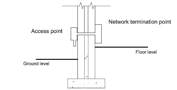
In multi-occupancy buildings the in-building physical infrastructure should be taken to an individual network termination point within each building unit in different occupation. Such infrastructure may consist of a single duct from a main access point outside the building, leading to a common access point within the building, which is usually located in a communal service riser. The infrastructure from the common access point to the individual termination points may be either:
a.a single duct, appropriately sized and designed to suit the technology (including cabling) that is, or may be expected to be, available to the building and should be continuous from the common access point to the network termination point within each building unit in different occupation, or
b.a cable tray taken to an appropriate point adjacent to each building unit with a suitably sized duct connecting the cable tray to a network termination point within each building unit in different occupation.
Figure 4.13 indicates one arrangement suitable for in-building physical infrastructure serving multi-occupancy buildings.
All ductwork and cable tray installations, including those entering areas of different occupation, should be designed and installed to take into account Section 2 (Fire), Section 5 (Noise), and Section 6 (Energy), having regard to the seals and fire-stopping, allowing easy access for cable installation.
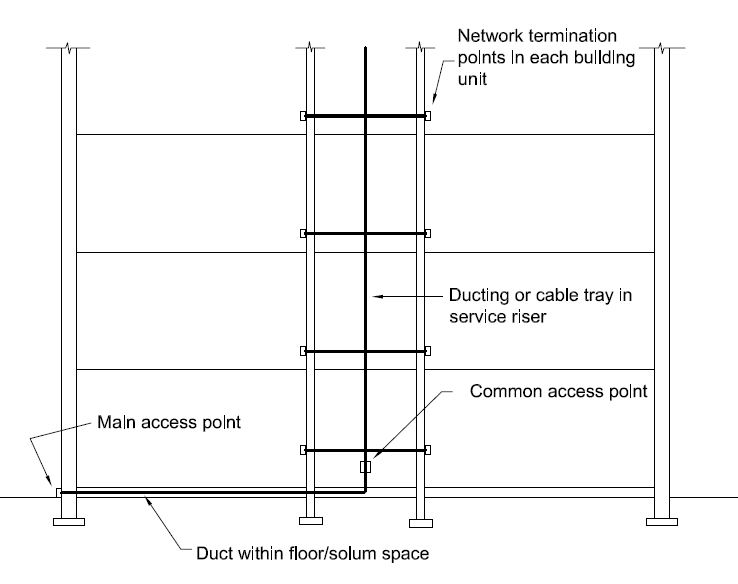
Consideration should be given to any additional works that may be necessary to facilitate the future installation of cabling, for example draw ropes within ducts. Where the internet service provider is known, they should be consulted.
4.14.2 Satellite and wireless communications
Although the preferred option for providing high-speed internet to the site of a building will usually be cable, it is recognised that there will be instances where this is not practical, for example, in remote areas. In such instances in-building physical infrastructure suitable for satellite or wireless communications should be provided in place of the infrastructure for cable or fibre where a minimum network speed of 30 Mbps is, or will be, available.
5.0 Introduction
#Source page 86
5.0.1 Background
Noise is unwanted sound. In order to limit the effects of unwanted sound the standards intend to improve the resistance of building elements to sound transmission. Research has presented clear evidence that noise can indirectly contribute to a range of health issues such as stress and anxiety.
Inadequate sound insulation can impair health by allowing noise from other people to disrupt normal life. A number of people in residential buildings complain of noise made by others. The World Health Organisation has established a relationship between noise exposure and sleep disturbance however the next-day or long-term effects are still not clear.
5.0.2 Aims
The purpose of the standards in Section 5 is to limit the transmission of sound to a level that will not threaten the health of occupants from sound transmission emanating from attached buildings and a differently occupied part of the same building. They also cover sound from within the same dwelling if occupants are in rooms where they would expect to have some degree of peace and quiet.
It is important to recognise that the standards will not guarantee freedom from unwanted sound transmission. The standards aim to limit the effects from sound created from normal domestic activities, but not from excessive noise from things such as power tools, audio systems inconsiderately played at high volume or even raised voices.
The standards do not address environmental noise through the building facade from sources such as aircraft, trains, road traffic or industry. Other legislation covers these areas and further information may be obtained from Planning Advice Note PAN 1/2011 ‘Planning and Noise’.
5.0.3 Latest changes
The following is a summary of the main change that has been introduced since 1 October 2010.
•Standard 5.1 - removal of guidance regarding the phased introduction of sound tests.
5.0.4 Explanation of terms
There are a number of terms used in this section some are included below, these and other useful terms are included in Annex A of the Example Constructions.
Airborne sound is sound which is propagated from a noise source through the medium of air. Examples of these are speech and sound from a television.
Airborne sound transmission is direct transmission of airborne sound through walls or floors. When sound energy is created in a room, for instance by conversation, some of the energy is reflected or absorbed by room surfaces but some may set up vibrations in the walls and floor. Depending on both the amount of energy and the type of construction, this can result in sound being transmitted to adjacent parts of the building.
Direct transmission refers to the path of either airborne or impact sound through elements of construction.
DnT,w is the weighted standardised level difference. A single-number quantity (weighted) which characterises the airborne sound insulation between two rooms, in accordance with BS EN ISO 717-1: 1997.
Flanking transmission is airborne or impact transmission between rooms that is transmitted via flanking elements and/or flanking elements in conjunction with the main separating elements. An example of a flanking element is the inner leaf of an external wall that connects to the separating ‘core’ of a wall or floor.
Impact sound is sound which is propagated from a noise source through a direct medium. An example of this is footfall on a floor.
Impact sound transmission is sound which is spread from an impact noise source in direct contact with a building element.
L’nT,w is the weighted standardised impact sound pressure level. A single-number quantity (weighted) to characterise the impact sound insulation of floors, in accordance with BS EN ISO 717-2: 1997.
Rw is a single number quantity (weighted) which characterises the airborne sound insulation of a building element from measurements undertaken in a laboratory, in accordance with BS EN ISO 717-1: 1997.
5.0.5 Reduction of sound transmission
The reduction of sound transmission from attached buildings and within buildings can be provided through different mechanisms which involve mass, isolation, absorption, resilience and stiffness (see annex A of the Example Constructions). Wall and floor constructions that provide a combination of such mechanisms generally provide better sound insulation.
Good design incorporates at least 2 or more of the above mechanisms and can reduce a range of sound frequencies typically found in attached residential buildings.
The effects these variables can have in predicting both sound transmission and insulation are as follows:
•through a heavyweight wall or floor it is its mass per unit area. A reduction in sound transmission and increase in sound insulation are expected with increasing mass, as the heavier the wall or floor, the less it vibrates in response to sound waves and hence the less sound energy is radiated. For example, heavyweight constructions such as masonry cavity walls provide mass and isolation
•through a lightweight wall or floor it is the use of cavities, structural coupling and absorption. A reduction in sound transmission and an increase in sound insulation are expected by the use of cavities with fewer and less stiff connections, while absorptive material hung in the wall cavity will absorb mid to high frequency sound energy. The formation of narrow cavities, such as dry linings on dabs, can also create an unwelcome ‘drum’ effect at low frequencies and filling or lining them with absorbing material can help to reduce this. For example in lightweight constructions such as timber frame walls, the twin stud of the timber frame provides isolation, stiffness and absorption
•resilience is often required for separating floors in residential buildings where there is direct vibration impact such as footfall noise. Resilience reduces the impact vibration by dynamic movement and also converts the energy into heat. Examples of resilient elements for floors include floating floor treatments such as battens and cradles, resilient bars and resilient floor coverings, other than carpet
•mass and stiffness help to reduce significantly low frequency sound transmission whereas absorption and resilience predominantly reduce mid and high frequency sound transmission
•isolation has the most influence over all frequencies of sound but can be limited by structural connections such as wall ties, straps and fixings that may bridge isolated leafs or elements.
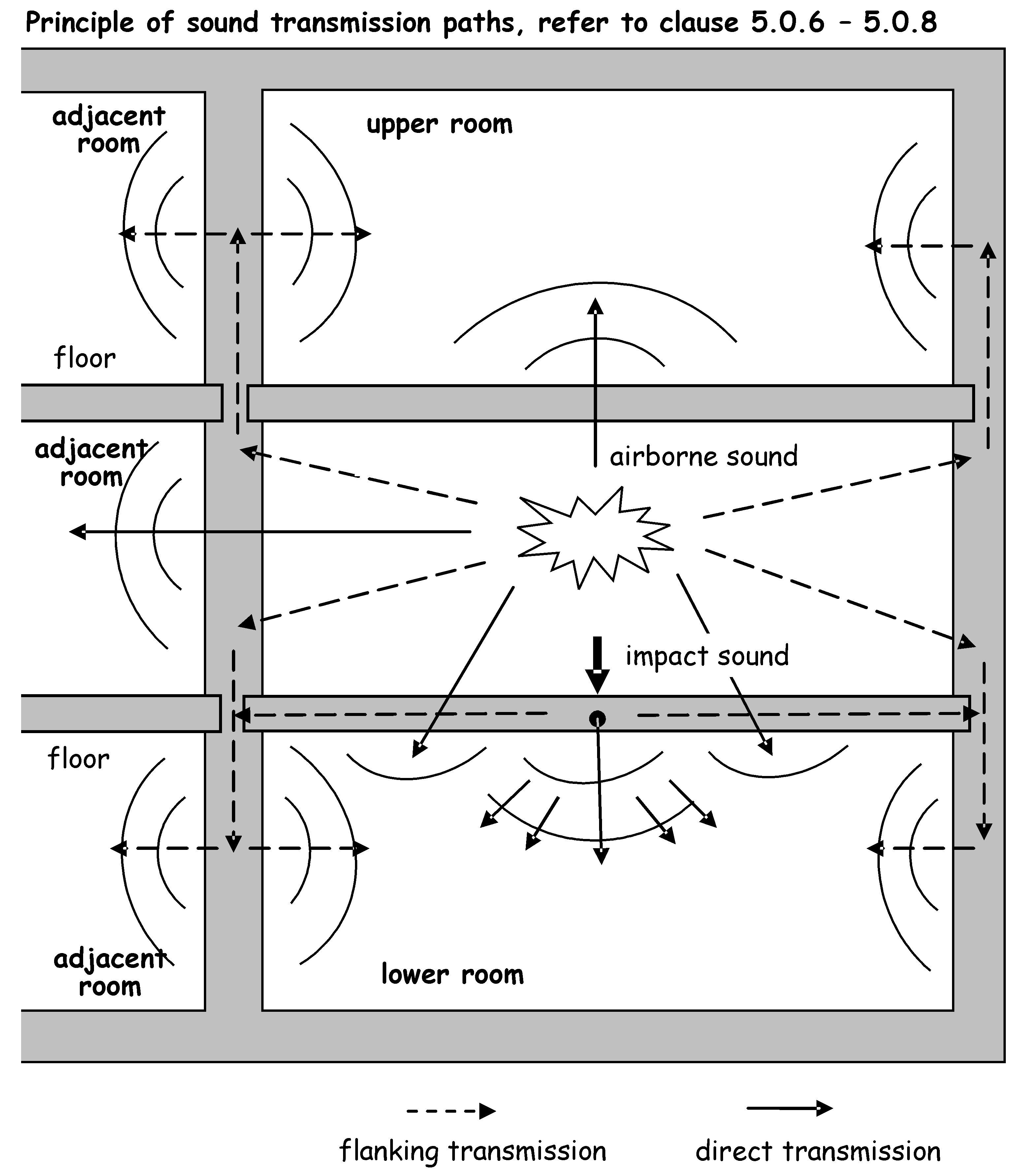
5.0.6 Principles of airborne sound transmission
When sound waves strike a wall or floor, the pressure variations cause the construction to vibrate. A portion of the vibrational energy on the sound source side will be transferred through the wall or floor where it is radiated as airborne sound on the other side. There is a loss in sound transmission as the frequency of the incident sound (sound waves produced from striking against a wall or floor for example) increases. This also varies with the direction of the sound waves, and is usually assumed to be the average for all possible angles of incidence.
5.0.7 Principles of impact sound transmission
Impact sound is sound that is spread from an impact or vibrational source in direct contact with a building element such as a floor. A structural vibration is transmitted from the point of impact through the structure causing vibration leading to the radiation of sound into an adjacent room below. In a building this is commonly caused by an object hitting the floor, from where the vibration is transferred into the structure. Usually the vibration path will lead to the ceiling and perimeter walls below. The amount of impact sound heard below will depend upon many factors including the force of the impact, the vibration transmission characteristics of the floor construction and the floor covering.
5.0.8 Principles of flanking sound transmission
Flanking sound transmission occurs when there is an indirect path for sound to travel along elements adjacent to walls and floors. If the flanking construction and its connections with the separating structure are not correctly detailed, flanking transmission can equal, or even exceed, sound levels perceived as a result of direct transmission. Flanking transmission can occur, for instance, when a wall abuts the face of the inner leaf of an external cavity wall, and the walls are insufficiently tied or bonded together, thus allowing the noise to travel along the inner leaf.
5.0.9 Relevant legislation
Listed below are some pieces of legislation and guidance that may be relevant and/or helpful to those using the guidance in this particular section.
The Common Law of Nuisance recognises that an occupant has the right to the free and absolute use of the property, but only to the extent that such use does not discomfort or annoy a neighbour.
Part IV of the Civic Government (Scotland) Act 1982 sets out a range of public nuisance offences.
The Environmental Protection Act 1990 as it relates to noise, states that ‘any premises in such a state as to be prejudicial to health or a nuisance ranks as a statutory nuisance’.
The Human Rights Act 1998 (as it relates to noise) Article 8 guarantees the right to respect for private and family life.
Antisocial Behaviour etc. (Scotland) Act 2004 empowers the local authority to serve a warning notice in relation to noise which exceeds the permitted level.
The Planning Advice Note PAN 1/2011 ‘Planning and Noise' provides advice on the role of the planning system in helping to prevent and limit the adverse effects of noise.
The SHTM 2045 provide guidance on designing for noise in hospitals and healthcare facilities.
5.0.10 Certification
Scottish Ministers can, under Section 7 of the Building (Scotland) Act 2003, approve schemes for the certification of design or construction for compliance with the mandatory functional standards. Such schemes are approved on the basis that the procedures adopted by the scheme will take account of the need to co-ordinate the work of various designers and specialist contractors. Individuals approved to provide certification services under the scheme are assessed to ensure that they have the qualifications, skills and experience required to certify compliance for the work covered by the scope of the scheme. Checking procedures adopted by Approved Certifiers will deliver design or installation reliability in accordance with legislation.
5.1 Noise separation
#Source page 87
Mandatory Standard
| Standard 5.1 Every building, which is divided into more than one area of different occupation, must be designed and constructed in such a way to limit the transmission of source noise from normal domestic type activities, between such areas, to a level that will not threaten the health of, or cause inconvenience to the building occupants. Limitation: This standard only applies to a building in different occupation incorporating: |
5.1.0 Introduction
Noise nuisance affecting people who stay in residential buildings such as hotels or care homes has risen over the years as rooms are used for more than just sleeping accommodation. These rooms are now multi-functional, and greater numbers of noise-producing pieces of equipment and appliances such as audio and TV are now used. Noise generated by people in hotel corridors as they move about and bang doors or talk loudly can cause disturbance to those trying to sleep in nearby rooms.
Complaints regarding noisy services are made regularly. Dealing with the varying levels of sound produced by service equipment, such as lifts, heat pumps or air conditioning units in buildings is a complex task, and not an issue specifically dealt with here. However guidance is given on special care that should be taken at the decision stage in the choice of service equipment, their installation and location within the building.
Designers should be aware that some Local Authorities' may also set noise reduction targets. This is usually enforced through environmental health and planning legislation for noise emanating from non-domestic premises. More information on this is contained in PAN1/2011.
Conversions - in the case of conversions as specified in regulation 4, the building as converted shall meet the requirement of this standard (regulation 12, schedule 6).
5.1.1 Scope of standard
Airborne sound insulation should be provided where any separating wall or separating floor is formed between areas in different occupation. For example:
•between rooms that are intended to be used for sleeping and other buildings
•between rooms that are intended to be used for sleeping and other parts of the same building, such as bedrooms and a communal hall.
Impact sound insulation should be provided where any separating floor is formed between areas in different occupation. For example:
•between rooms intended to be used for sleeping. The lower room should be protected from sound emanating from the upper room
•between rooms intended to be used for sleeping and other parts of the same building. The room below should be protected from sound emanating from other parts of the building above
•between rooms intended to be used for sleeping and other parts of the same building directly above e.g. common stair or corridor, communal lounge, or car parking garage
•a roof, walkway or access deck located directly above rooms intended to be used for sleeping and to which there is access, other than where it meets the conditions of (c) or (d) below.
Impact sound insulation need not be provided for:
a.a roof above a non-habitable space, such as a roof space
b.a separating floor between a residential building and any other non-domestic building directly below
c.a roof, walkway or access deck located directly above rooms intended to be used for sleeping to which there is access for maintenance purposes only
d.a roof, walkway or access deck located directly above rooms and to which there is access, where it is for the sole use of the residents of the residential building.
5.1.2 Design performance levels
The following design performance levels are given for the control of sound through separating walls and separating floors. Although not specifically covering non-domestic buildings, the levels have been developed from research covering sound and perceived sound in dwellings. They have been identified as levels based on normal domestic activities that have been shown to produce few noise complaints.
However experience shows that the performance of a construction is dependent upon:
•achieving a high quality of workmanship on site
•supervision throughout the construction process
•the relationship between separating and adjoining elements (e.g. external walls, roofs and windows) to combat flanking transmission
and these factors should be carefully considered at the design stage.
All work should be designed to the levels in the following table:
Table 5.1. Design performance levels in dB [1]
| Design Performance | New build and conversions not including traditional buildings | Conversions of traditional buildings [2] |
|---|---|---|
| Minimum airborne sound insulation [3] | 56 DnT,w | 53 DnT,w |
| Maximum impact sound transmission [3] | 56 L’nT,w | 58 L’nT,w |
Additional information:
1.For the definition of DnT,w and L’nT,w see clause 5.0.4.
2.Notice should be taken of the guidance on conversions in clause 5.1.5.
3.See clause 5.1.1 for application of these performance levels to separating walls and separating floors.
Two methods are provided on ways to achieve these levels which can lead to meeting the standard. They are by the use of:
a.Example Constructions (see clause 5.1.3), or
b.other constructions (see clause 5.1.4).
These methods are to be used in conjunction with the testing arrangements (see clause 5.1.7 to 5.1.9).
5.1.3 Example Constructions
Example Constructions have been developed that will repeatedly achieve the design performance levels in the table to clause 5.1.2. They have also been developed from constructions that are in general use in the UK, and that are known to reduce the range of sound frequencies that can generate complaints. As these are designed for domestic types of construction they may not be suitable for use in non-domestic buildings.
The Example Constructions are available on the BSD website http://www.scotland.gov.uk/topics/built-environment/building/building-standards.
5.1.4 Other constructions
Clause 5.1.3 provides guidance on constructions that have been designed and tested to repeatedly achieve the performance levels in the table to clause 5.1.2. However it may be necessary, preferable or desirable, to include new or innovative constructions into a proposed design.
Where constructions that have not been tested previously are used, the services of an acoustic specialist may be obtained, who should be able to offer design guidance on constructions that are capable of achieving the performance levels in the table to clause 5.1.2.
5.1.5 Conversions
Achieving the design performance levels for conversions can present challenges to a designer. The presence of hidden voids within constructions, back to back fireplaces, cupboards and gaps between construction elements in walls and floors, mean that it may not be possible to use ‘pattern book’ type constructions to achieve the design performance levels. When conversions are undertaken, the adaption of the existing building should be considered at the design stage. Conversions and conversions of traditional buildings should achieve the performance levels in the table to clause 5.1.2.
With older buildings achieving the performance levels in clause 5.1.2 becomes more difficult, therefore the levels for traditional buildings are less demanding than for new build and conversions.
The design proposals for the conversion of a traditional building should be considered carefully so that any measures taken will improve the sound insulation. The performance levels in the table to clause 5.1.2 should be considered as a benchmark, but it may not be possible to achieve these levels in all circumstances. Consultation on such matters at an early stage with both the verifier and the planning officer of the relevant authority is advisable.
Historic and Listed buildings will prior to conversion display unique characteristics as far as sound insulation is concerned. The original building design and construction will influence the level of sound insulation achievable for the separating walls and separating floors. For this reason, specific prescriptive guidance on such buildings is not appropriate. The relevant authority may, at their discretion, agree measures that respect the character of the building.
Although not specifically covering non-domestic buildings further advice on providing sound insulation in listed buildings can be obtained from the Building Performance Centre, Napier University booklet ‘Housing and Sound Insulation – Improving existing attached dwellings and designing for conversions' http://www.scotland.gov.uk/topics/built-environment/building/building-standards.
The building owner may wish to carry out a pre-conversion sound test prior to the start of any conversion, ideally during the building survey process. The acoustic performance of the existing construction can then be established and problems identified that will allow the design of a tailored acoustic solution to be determined at an early stage.
For larger or more complex work, advice on conversions may be sought from an acoustic specialist who should be able to offer appropriate design guidance.
5.1.6 Noise from services
Building service installations serving common areas in residential buildings have the potential to cause noise nuisance. For example, common plant such as lifts, air conditioning units, ventilation systems, and drainage pipes running the height of a building have all been known to be a source of complaint.
Therefore, it is important that the design of building services, their position in the building and the building structure should be considered at an early stage in the design process.
Services passing through separating walls or separating floors must comply with the relevant standards in Section 2: Fire.
Service pipes or ducts should not pass through a separating wall, unless they are of small diameter, such as lateral pipework from network risers such as gas, electricity, water and telecom. These pipes or ducts may pass through a separating wall from a common area only.
Custom-built or system chimneys should not be built into timber-framed separating walls. Only masonry chimneys (including precast concrete flue-blocks) may be included as an integral part of a separating wall. However, some thickening of the construction may be necessary to achieve the performance levels in clause 5.1.2.
Only service openings for ducts, service pipework or chimneys may be formed in separating floors. These services should be enclosed above and below the floor with a construction that will maintain the levels of noise reduction recommended for a separating floor in the table to clause 5.1.2.
Service equipment rooms should not be located next to quiet areas such as rooms intended for sleeping. Locating plant in a larger space can help dissipate sound. Also, plant machinery and equipment such as lift rails should be isolated from the walls and floor to reduce vibrations and the resulting sound transmission to rooms intended for sleeping. Vibration from mechanical equipment can be reduced with the use of inertia blocks and resilient mounts.
Structure borne noise is the most common cause of complaints and the most effective approach is to structurally de-couple service installations and mechanical equipment from separating walls and separating floors. Lightweight structures need special consideration and it may be necessary to support noisy plant on a separate, rigid structure. The installation of an independent wall or ceiling lining may help achieve the performance levels in clause 5.1.2.
Although not specifically covering non-domestic buildings, a report ‘Limit noise transmission to dwellings from services' includes several useful design guide annexes http://www.scotland.gov.uk/topics/built-environment/building/building-standards. Annex H of BS EN 12354-5: 2009 provides more detailed guidance on the reduction of service noise transmittance through separating walls and separating floors.
Design guides covering low carbon equipment, such as air source heat pumps, contain advice on sound reduction measures and are available at http://www.scotland.gov.uk/topics/built-environment/building/building-standards.
5.1.7 Post-completion performance test levels
The effectiveness of a construction to reduce sound transmission depends on several factors; the design, the buildings within which it is formed and the quality of the workmanship.
The use of any of the methods listed in clause 5.1.2 alone will not guarantee that the performance levels will be achieved. Good workmanship is essential to their performance, and post-completion testing will confirm these levels have been achieved.
Table 5.2. Test levels for Example and other constructions in dB [1]
| Design Performance | New build and conversions not including traditional buildings | Conversions of traditional buildings [2] |
|---|---|---|
| Minimum airborne sound insulation [3] | 56 DnT,w | 53 DnT,w |
| Maximum impact sound transmission [3] | 56 L’nT,w | 58 L’nT,w |
Additional information:
1.For the definition of DnT,w and L’nT,w see clause 5.0.4.
2.Notice should be taken of the guidance on conversions in clause 5.1.5.
3.See clause 5.1.1 for application of these performance levels to separating walls and separating floors.
5.1.8 Post-completion testing
On completion, new buildings and conversions should be tested. At least 1 test should be carried out on each separating wall and separating floor of different construction within the completed buildings, where there is a room intended for sleeping.
Inaccessible areas - there may be some locations where it is not possible to carry out a sound test, as access to an adjoining building may be restricted or prevented. When a conversion of an attached building occurs, for example to a mid terrace building, it may not be possible to gain access to the adjacent building to carry out tests to the separating wall. In such cases, it may not be appropriate to test.
Methods of testing - sound tests should only be carried out on a building that is complete and when doors, access hatches and windows are fitted. Carpet, should not be used as bonded resilient floor covering or laid before an impact test for separating floors. Sound testing should be carried out in accordance with:
a.BS EN ISO 140-4: 1998 and BS EN ISO 717-1: 1997, for airborne sound transmission, and
b.BS EN ISO 140-7: 1998 and BS EN ISO 717-2: 1997, for impact sound transmission.
At least two different loudspeaker positions should be used for the source noise, in accordance with BS EN ISO 140-4: 1998.
Methods using a single source - for each source position, the average sound pressure level in the source and receiving rooms is measured in one-third-octave bands using either fixed microphone positions (and averaging these values on an energy basis), or using a moving microphone.
For the source room measurements, the difference between the average sound pressure levels in adjacent one-third-octave bands should be not more than 6dB. If this condition is not met, the source spectrum should be adjusted and the source room measurement repeated. If the condition is met, the average sound pressure level in the receiving room, and hence a level difference, should be determined.
It is essential that all measurements made in the source and receiving rooms to determine a level difference should be made without moving the sound source or changing the output level of the sound source, once its spectrum has been correctly adjusted (where necessary).
The sound source should now be moved to the next position in the source room and the above procedure repeated to determine another level difference. At least two positions should be used for the source. The level differences obtained from each source position should be arithmetically averaged, D as defined in BS EN ISO 140-4: 1998.
Airborne and sound impact insulation testing - for both types of testing it is possible to use fixed microphone positions, rotating booms or manual moving microphones (mmm), in accordance with BS EN ISO 140-4: 1998 and BS EN ISO 140-7: 1998.
Professional expertise - testing should be carried out by persons who can demonstrate relevant, recognised expertise in acoustics for sound insulation testing. This should include membership of a professional organisation which accredits its members as competent to both test and confirm the results.
5.1.9 Remedial action following a test failure
Noise transmission in buildings is a complex subject and it is difficult to provide definitive guidance on resolving specific problems that have occurred in individual buildings. It may be prudent to seek advice from a specialist who, through experience of sound testing, may be able to identify and resolve any problems.
If the failure is attributed to the construction of the separating and/or associated flanking elements, other rooms that have not been tested may also fail to meet the test performance levels. Additional tests may be needed, over and above the number recommended in clause 5.1.8 to check that the work achieves the test performance levels.
5.2 Noise reduction between rooms
#Source page 88
Mandatory Standard
| Standard 5.2 Every building, must be designed and constructed in such a way to limit the transmission of source noise from normal domestic type activities, through a wall or floor, between a room and internal space where noise is likely to occur, to a level that will not cause inconvenience to the building occupants. Limitation: This standard only applies to a wall or floor forming an apartment in a dwelling and a room in a residential building which is capable of being used for sleeping; other than: |
5.2.0 Introduction
In the past many noise complaints have came, from occupants of residential buildings, such as hotels, residential care buildings and student residences. In most cases, these tend to occur where there is noise transfer from communal areas, particularly when people return late, bang doors or talk too loudly, and to a lesser extent noise between rooms.
Although noise within a unit of residential accommodation can be controlled by the management to a certain extent, it is not possible to control all of the noise made from everyone and every source within the building. This increase in noise levels from speech and music within individual units can lead to anxiety and stress.
NHS regulations, SHTM 2045, provide guidance on designing for noise in hospitals and healthcare facilities.
The Scottish Prison Service produces guidance on the design requirements for places of lawful detention.
Conversions - in the case of conversions as specified in regulation 4, the building as converted shall meet the requirements of this standard (regulation 12, schedule 6).
5.2.1 Design performance level
Internal walls are normally built off the structural floor. A door located in such a wall provides a path for sound to bypass a wall under test. On-site sound testing of internal walls and intermediate floors cannot be relied upon due to excessive flanking sound transmission through doors. For this reason a laboratory test is used. A laboratory test result is termed dB Rw.
As disturbance to occupants can occur from other areas within a residential building, the level of sound heard should be reduced in the rooms in which people may sleep. Therefore it is the internal walls between rooms, rooms intended for sleeping and an internal space where noise is likely to occur that should achieve the sound performance level. An internal wall between an en-suite bathroom and the room it serves need not have sound insulation.
The design performance levels for internal walls and intermediate floors covered by this standard should achieve a minimum airborne sound insulation level of 43 dB Rw.
5.2.2 Internal walls
The design performance levels in clause 5.2.1 can be achieved by using the Generic Internal Constructions available on the BSD website http://www.scotland.gov.uk/topics/built-environment/building/building-standards. Alternatively, product manufacturers may have solutions that will achieve the design performance level.
5.2.3 Intermediate floors
Improving the sound insulation over parts of an intermediate floor only above or below rooms that are intended for sleeping, could lead to expensive remedial measures if an area is missed or if future alteration work is carried out. It is therefore recommended that sound insulation should be provided across the entire area of each intermediate floor if there is a room that is intended for sleeping, located directly above or below the floor.
The design performance levels in clause 5.2.1 can be achieved by using the Generic Internal Constructions available on the BSD website http://www.scotland.gov.uk/topics/built-environment/building/building-standards. Alternatively, product manufacturers may have solutions that will achieve the design performance level.
Although setting impact sound insulation design levels for intermediate floors is not reasonably practicable, insulation against impact noise can be improved by adding a soft covering such as a carpet or foam-backed vinyl. However a carpet or foam-backed vinyl is a floor covering and should not be included as part of the construction used to achieve the design levels in clause 5.2.1.
5.2.4 Conversions
Many of the existing wall and floor constructions within a traditional building, will be constructed from materials generally not still in use, for example lath and plaster. In such cases the sound insulation level will not be known therefore, it is not reasonably practicable for the existing walls or floors to meet the performance levels in clause 5.2.1.
5.2.5 Doors in internal walls
Doors in residential buildings that provide direct access from common areas to rooms intended for sleeping, such as hotel bedrooms create a weak point in the wall, acoustically. This allows unwelcome noise into the room. Noise can more readily pass through a lightweight door than a heavy door and, the weakest point for noise to enter will be through the gap between the door and the frame.
Rooms intended for sleeping should be separated by a door that will act as a sound barrier and reduce noise transference. Therefore, a door that provides direct access to a room intended to be used for sleeping should have an overall mass per unit area of at least 25 kg/m2.
The door should also be fitted with a perimeter seal, excluding the threshold, to minimise noise transmittance through the doorset. A compressible type of seal may be used, such as a rubber strip. Where the seal is of a type that combines a smoke and noise seal, the product literature should be consulted to confirm the seal will achieve the desired effect. The seal should not interfere with the closing mechanisms of a fire door and provide a positive seal between the door frame and the door.
6.0 Introduction
#Source page 89
6.0.1 Background
Within Scottish building regulations, improvements in energy standards have been made over many years, including in 2007, the move to a single carbon dioxide emission based methodology for assessing carbon and energy performance in new buildings.
The Sullivan Report - in 2007, Scottish Ministers convened an expert panel to advise on the development of a low carbon building standards strategy to increase energy efficiency and reduce carbon emissions. This resulted in The Sullivan Report – ‘A Low Carbon Building Standards Strategy for Scotland’ (http://www.scotland.gov.uk/Sullivanreport). A key recommendation of this Report was staged improvements in energy standards in 2010 and 2013, with the aim of net zero carbon buildings (emissions for space heating, hot water, lighting and ventilation) in 2016/17, if practical.
In May 2013 Scottish Ministers reconvened the Sullivan panel with a view to revisiting some of their original recommendations, taking account of the impact of the economic downturn on the construction sector. Whilst maintaining the level of ambition, the 2013 Update report recommended a more moderate pace of change and offered recommendations in three areas:
•eventual and staged standards – Percentage improvements recommended in 2007
•process – Extending carbon compliance beyond site - related measures and
•costings – Recognising the value of new - build energy standards.
The Climate Change (Scotland) Act 2009 (http://www.legislation.gov.uk/asp/2009/12/pdfs/asp_20090012_en.pdf) creates a statutory framework for delivery of greenhouse gas emissions reductions in Scotland. The Act sets an interim target of a 42% reduction in emissions (compared to 1990) by 2020, and an 80% reduction target for 2050 with annual targets set in secondary legislation. The high level measures required in each sector to meet Scotland’s statutory climate change targets, for 2022 and in the long term, were set out in the Scottish Government’s Climate Change Delivery Plan. This includes recommendations for the delivery of low carbon new buildings.
The construction sector has a major role to play in this respect. Emissions from the burning of fossil fuels are contributing to climate change, with energy use in buildings being a significant source of such emissions. Increased energy efficiency and promotion of renewable energy are therefore an important element of Scotland’s strategy to tackle climate change.
To deliver buildings that are more energy efficient and have fewer carbon dioxide emissions, a greater emphasis is needed on the overall effect that design and specification choices, construction and commissioning of new work can have on building performance.
6.0.2 Aims
The intention of Section 6 is to ensure that effective measures for the conservation of fuel and power are incorporated in buildings. In addition to limiting energy demand by addressing the performance of the building fabric and fixed building services, a carbon dioxide emissions standard obliges designers of new buildings to consider building design in a holistic way.
Improvements set out within this section will result in a greater need to consider the benefits which localised or building-integrated low carbon equipment (LCE) (e.g. photovoltaics, solar water heating, combined heat and power and heat pumps) can make towards meeting standards. Although the focus is primarily on lowering carbon dioxide emissions from buildings, the measures within this section are intended to reduce energy demand and continue to ensure that, for new buildings and new building work, use of energy and fuel costs arising from this are both minimised.
Guidance also recognises issues relevant to requirements within Articles 3, 4, 6-9 and 11 of the EU Directive 2010/31/EU on the Energy Performance of Buildings (EPBD) and Article 13 of the EU Directive 2009/28/EC http://europa.eu/legislation_summaries/energy/renewable_energy/en0009_en.htm on the promotion of the use of energy from renewable sources.
The standards and guidance given in this section are intended to achieve an improvement, for new buildings reducing emissions by approximately 43% compared to the previous 2010 standards (60% compared to the 2007 Standards). However nothing here prevents a non-domestic building from being designed and constructed to be even more energy efficient or make greater use of low carbon equipment (LCE).
6.0.3 General guidance
This section covers the energy efficiency for non-domestic buildings. Such buildings include: factories, offices, shops, warehousing, hotels, hospitals, hostels and also buildings used for assembly and entertainment.
This section should be read in conjunction with all the guidance to the Building (Scotland) Regulations 2004, but in particular Section 3 Environment, which has a close affiliation with energy efficiency, regarding:
•ventilation
•condensation
•combustion appliances, and
•biomass fuel storage.
When determining how to follow the Section 6 guidance for energy efficiency in buildings, recognition should be given to the following:
a.an insulation envelope is only appropriate to those parts of a building that are intended to be heated or cooled. N.B. Heating rated at a maximum of 25W/m2 of floor area and installed only for the purposes of frost protection should be disregarded for the purposes of this guidance
b.some concessions are given in annex 6C to modular and portable buildings (some of which could be stand-alone buildings). The flowchart in the annex gives guidance on possible compliance routes. Note there are no concessions for limited life buildings which are constructed in a conventional manner
c.stand-alone buildings that are heated (see paragraphs below), and
d.work on existing buildings (see paragraph below).
Heated stand-alone buildings - in 2007, the EU Directive 2002/91/EC on the energy performance of buildings introduced the category ‘stand-alone building’, a definition of which is given and within appendix A of the Technical Handbooks. The Directive, now recast as Directive 2010/31/EU, exempts such buildings, where less than 50m2 in floor area, from both the need to use a methodology to calculate energy performance (Standard 6.1) and also the production of an Energy Performance Certificate (Standard 6.9). The defined term includes not only detached buildings, but also thermally divided parts of a building with separate heating shut-down control.
Stand-alone buildings that are less than 50m2 in floor area, must still comply with Standards 6.2 to 6.8 and 6.10. The guidance to Standard 6.2 recommends that the insulation envelope of heated stand-alone buildings meets the level of performance applicable to an extension.
Examples - common examples of stand-alone buildings that could be less than 50m2 and which would therefore be eligible for exemption are: a detached petrol filling station kiosk, associated with a supermarket; and heated office and toilet accommodation, within an otherwise unheated warehouse.
Work on existing buildings - as for other standards within Scottish building regulations, the energy standards apply to conversions and also work on existing buildings, such as extensions, alterations and fit-outs. However in some situations, individual standards may not apply or guidance on compliance with the standards may differ for such work. The latter is usually to recognise constraints that arise when working with existing buildings.
It is advisable in the first instance to check the functional standard as sometimes a limitation removes certain classes of this type of work. Where not excepted by a limitation to the standard, the provisions of the standard will apply in full to the new work on the existing building, the exception to this could be where the standards are brought into effect by conversion and this is identified in the introduction to the guidance supporting each standard.
6.0.4 U-values
Thermal transmittance (U-value) is a measure of how much heat will pass through one square metre of a structure when the temperature on either side differs by one degree Celsius. It is expressed in units of watts per square metre per degree of temperature difference (W/m2K).
Measurements of U-values should be made in accordance with BS EN ISO:8990:1996 ‘Thermal insulation. Determination of steady-state thermal transmission properties. Calibrated and guarded hot box’. In calculation thermal bridging may be disregarded where the difference in thermal resistance between bridging and bridged material is less than 0.1m2K/W. For example, normal mortar joints need not be taken into account in calculations for brickwork, but should be taken into account for lightweight insulating blockwork.
Taking into account guidance from BRE publication BR 443:2006 ‘Conventions for U-value calculations’ (http://www.bre.co.uk/filelibrary/pdf/rpts/br_443_(2006_edition).pdf), individual U-values of building elements forming the insulation envelope should be established:
a.by using insulation to a thickness derived from manufacturers’ data relating to thermal conductivities (W/mK) and thermal transmittances (U-values: W/m2K) certified by a notified body
b.by calculation taking into account thermal bridging effects of, e.g. timber joists, structural and other framing and normal bedding mortar, by using the Combined Method set out in BS EN ISO 6946:2007 or CIBSE Guide Section A3, 2006 Edition (http://www.cibse.org/)
c.for floors adjacent to the ground and basements, by using the method set out in BS EN ISO 13370: 2007 or CIBSE Guide Section A3, 2006 Edition
d.for windows, doors and rooflights, by using BS EN ISO 10077-1: 2006 or BS EN ISO 10077-2: 2012 and, for rooflights, BS EN ISO 12567-2: 2005, or
e.for metal cladding systems using Finite Element Analysis, the method of calculation should be made in accordance with BS ISO 10211:2007.
6.0.5 Thermal conductivity
The thermal conductivity λ (the λ-value) of a material is a measure of the rate at which that material transmits heat and is expressed in units of watts per metre per degree of temperature difference (W/mK). Establishing the thermal conductivity of materials in a building element forming part of the insulation envelope will enable the thermal transmittance of the element to be calculated.
Measurements of thermal conductivity should be made in accordance with BS EN 12664: 2001, BS EN 12667: 2001 or BS EN 12939: 2001 (http://www.bsigroup.com/). There are a wide range of technical publications which give the thermal conductivity of common construction materials but, where available, preference should be given to values that are certified by a notified body. Additional guidance given in BRE publication BR 443 should also be followed.
6.0.6 Thermal transmittance through separating elements
Previously, thermal transmittance through separating walls or separating floors between heated parts of the same building (e.g. between an office and a protected zone with space heating) was not assessed. Accommodation on both sides of the separating element was expected to be at a similar temperature when the buildings are occupied.
This is no longer always the case. Whilst ‘no loss’ may still be assumed for solid walls, research has identified previously unanticipated heat losses from air movement in cavity separating walls. This ‘thermal bypass’ is now identified in the calculation methodology and guidance to Standard 6.1 and in guidance to Standard 6.2.
6.0.7 Buffering effects on the insulation envelope
If a building or part of a building is separated from an unheated enclosed area, (e.g. solid waste storage accommodation, a porch, garage, protected zone or underground car park) the U-values of the walls/floors (including doors and translucent glazing) may be calculated by:
a.disregarding the buffering effects and treating the element as if it is directly exposed to the outside
b.following the procedure in BS EN ISO 6946: 2007, or
c.following the procedure in BS EN ISO 13789: 2007.
6.0.8 Roofs that perform the function of a floor
A roof of a building that also performs the function of a floor or similar load-bearing surface (e.g. an access deck, escape route, roof garden or car park), should be considered as a roof for the purpose of assessment within this section.
6.0.9 Atria
In a building with an atrium the guidance given in clause 6.0.7 applies if the atrium is unheated and thermally divided from the remainder of the building by translucent glazing and doors and, if appropriate, walls and floors. In other situations involving atria, where none of the above occurs, the continuity of the insulation envelope occurs at roof level (usually predominantly glazed with translucent material) and the atrium is considered to be a heated part of the main building.
6.0.10 Annexes to guidance
Annexes can be found at the back of this section. These give guidance in respect of various calculation procedures, modular and portable buildings and consequential improvement to fixed building services.
6.0.11 Performance of fixed building services
Unless otherwise identified in text, guidance given in support of Standards 6.3 to 6.6 now refers directly to information contained within the Non-domestic Building Services Compliance Guide for Scotland . The document replicates guidance published in support of building standards elsewhere in the UK and supports standardisation of the specification and expected performance of fixed building services throughout the UK.
Additional information, on the use of a range of low carbon equipment (LCE) such as solar thermal systems, photovoltaic panels and heat pumps, and application within building regulations can be found on the Technical Pages of the Building Standards Division website.
6.0.12 Calculation of areas
When calculating areas for the purposes of this section and in addition to regulation 7, schedule 4, the following should be observed:
a.all areas should be measured in square metres (m2), unless stated otherwise in this guidance
b.the area of a floor, wall or roof is to be measured between finished internal faces of the insulation envelope, including any projecting bays and in the case of a roof, in the plane of the insulation
c.floor areas are to include stairwells within the insulation envelope and also non-useable space (for example service ducts)
d.the area of an opening (e.g. window or door) should be measured internally from ingo to ingo and from head to sill or threshold.
6.0.13 Latest changes
The 2015 edition of Section 6 incorporates a number of changes whilst retaining the existing methodology introduced in 2007. The majority of these changes relate to improvement in specified performance to deliver the intended 43% aggregate reduction in carbon dioxide emissions on the 2010 standards (60% when compared to 2007 standards). Foremost, in guidance to Standard 6.1 is the move to use of a concurrent notional building specification to set the Target Emissions Rate for new buildings. A full summary of changes can be found on the Technical Handbooks page of the Building Standards Division section of the Scottish Government website.
The key changes that have been made to standards and guidance since 1 October 2013 include:
•Standard 6.1 - standard amended to apply to large extensions (over 100m² and more than 25% of the area of the existing building)
•Standard 6.1 – SBEM v5 now used to calculate carbon dioxide emissions; both changes to methodology and revised carbon factors for fuels apply
•Standard 6.1 – target Emissions Rate for new building now set using a concurrent (2015) notional building specification. Guidance comprehensively amended in support of this new approach (Revised NCM Modelling Guide for Scotland also published)
•Clause 6.2.5 – revisions to calculation options for heat loss from linear thermal bridging
•Clause 6.2.7 – revised list of situations where airtightness testing need not be undertaken
•Standard 6.9 - standard amended to cover display of EPC in public buildings over 250m2 (note: applies from 9 July 2015)
•Standards 6.3 to 6.6 - reference is now made to the Non-domestic Building Services Compliance Guide for Scotland for detailed guidance in support of each standard; any situations not addressed in this document are noted within the guidance to the relevant standard
•Annex 6C – guidance for new modular and portable buildings update to reflect revised emissions targets; exemption for relocation of buildings under 30m² now expired
•Annex 6G now published as Annex 6D; incorporating more comprehensive guidance on consequential improvement of fixed building services, taken from the published Direction
•Annexes 6E and 6F deleted – information now within the Non-domestic Building Services Compliance Guide for Scotland.
6.0.14 Relevant legislation
EU Directive 2009/28/EC - Directive 2009/28/EC (http://europa.eu/legislation_summaries/energy/renewable_energy/en0009_en.htm) promotes the use of energy from renewable sources, including promotion within national legislation. It establishes a common framework for the use of energy from renewable sources in order to limit greenhouse gas emissions, including establishment of national action plans and targets which set the share of energy from renewable sources for 2020.
6.0.15 Certification
Scottish Ministers can, under Section 7 of the Building (Scotland) Act 2003, approve schemes for the certification of design or construction for compliance with the mandatory functional standards. Such schemes are approved on the basis that the procedures adopted by the scheme will take account of the need to co-ordinate the work of various designers and specialist contractors. Individuals approved to provide certification services under the scheme are assessed to ensure that they have the qualifications, skills and experience required to certify compliance for the work covered by the scope of the scheme. Checking procedures adopted by Approved Certifiers will deliver design or installation reliability in accordance with legislation.
The Certification of Design (Section 6 – Energy) for Non-domestic Buildings scheme has been approved by Scottish Ministers to confirm compliance with Section 6. Details are available on the certification pages of the Building Standards Division website http://www.scotland.gov.uk/Topics/Built-Environment/Building/Building-standards/profinfo/cert.
6.1 Carbon dioxide emissions
#Source page 90
Mandatory Standard
| Standard 6.1 Every building must be designed and constructed in such a way that: Limitation: This standard does not apply to: |
6.1.0 Introduction
Standard 6.1 focuses on the reduction of carbon dioxide emissions arising from the use of heating, hot water, ventilation and lighting in new buildings and large extensions. The guidance sets an overall level for maximum carbon dioxide emissions in buildings by use of a methodology which incorporates a range of parameters that influence energy use. This means a designer is obliged to consider energy performance as a complete package rather than looking only at individual elements such as insulation or boiler efficiency - a ‘whole building approach’ to energy, which offers a significant degree of design flexibility.
For the majority of new buildings, Standard 6.1 has the greatest influence on design for energy performance. Standards 6.2 to 6.6 and 6.10, in the main, recommend benchmark and backstop levels to be achieved for individual elements or systems. To achieve compliance with Standard 6.1, it will be necessary to improve upon some or all of these backstop levels, or incorporate additional energy performance measures, such as low carbon equipment (LCE).
The guidance given in support of Standards 6.2 to 6.8 for extensions and alterations should be followed when designing stand-alone buildings of less than 50m2.
Renewable technologies - Directive 2009/28/EC [http://europa.eu/legistlation_summaries/energy/renewable_energy/en009_en.htm] promotes the use of energy from renewable sources. Where a building design will include use of renewable energy for heating, Article 13 of the Directive recommends, amongst other measures, consideration of use of the following:
•for biomass equipment, conversion efficiencies of 85%
•for heat pumps, those that fulfil the minimum requirements of eco-labelling established in Commission Decision 2007/742/EC (amended in 2011 & 2013) establishing the ecological criteria for the award of the Community eco-label to electrically driven, gas driven or gas absorption heat pumps, and
•for solar thermal systems, those that are subject to EU standards, including eco-labels and other technical reference systems established by the European standardisation bodies.
High-efficiency alternative systems - Article 6 of Directive 2010/31/EU [http://eur-lex.europa.eu/LexUriServ/LexUriServ.do?uri=OJ:L:2010:153:0013:0035:EN:PDF] requires that, for all new buildings, the technical, environmental and economic feasibility of high-efficiency alternative systems (such as decentralised energy supply systems using renewable energy, co-generation, district or block heating/cooling and heat pumps) are considered and taken into account in developing proposals.
This should be documented and available for verification purposes and a statement should therefore accompany the building warrant application. Further information on this process is provided in Annex 6.E - ‘Consideration of High-Efficiency Alternative Systems in New Buildings’.
Conversions - in the case of conversions as specified in regulation 4, this standard does not apply.
6.1.1 Simplified Building Energy Model (SBEM)
The Simplified Building Energy Model (SBEM) is a calculation tool which forms part of the UK National Calculation Methodology which conforms with Article 3 of Directive 2010/31/EU on the Energy Performance of Buildings. It is approved for use in carbon dioxide emissions calculations. SBEM has a basic user interface, iSBEM, which includes Scottish compliance parameters for use with this guidance and is available on the National Calculation Methodology website (http://www.ncm.bre.co.uk/index.jsp).
Other tools may be used with the methodology (such as dynamic simulation modelling), particularly where the building is considered to be a complex design. A list of approved calculation tools can be found on the 'Section 6 software' page of the Building Standards Division website. The guidance given here is written in terms of the SBEM calculation tool but the principles and procedures also apply to other calculation tools. Designers should be familiar with the NCM and their chosen software tool and be able to explain the input and calculation process in the context of the information submitted as part of the building warrant.
6.1.2 Summary of procedure
To comply with the requirements of Standard 6.1, designers should demonstrate that the calculated carbon dioxide emissions for the ‘actual’ building (Building Emissions Rate or BER) do not exceed those which are calculated for a ‘notional' building (Target Emissions Rate or TER). The carbon dioxide emissions are measured in kilograms of CO2 per square metre of floor area per annum.
Outline of process - in broad terms, the way that this process works is described below:
•The data defining the actual building is input into an approved software tool and the notional building is generated automatically by applying the National Calculation Methodology (NCM) for Scotland. The notional building has the same size, shape, orientation, conditioning strategy and zone activities as the actual building.
•The Target Emissions Rate (TER) for the actual building is generated automatically, with SBEM applying prescribed fabric and services specifications to the notional building (see clause 6.1.4). These are applied to the individual building zones that make up the notional building. Values are assigned automatically based upon both the activity and the conditioning strategy for each zone of the actual building, as input by the designer.
•Application of these specifications defines a ‘concurrent notional building’, i.e. one from which a calculated emissions rate is deemed to meet the requirements of this standard. This calculated figure is the TER for the actual building.
•The Building Emissions Rate (BER) is generated by applying the designer’s chosen fabric and services specifications for the actual building on a zone by zone basis within the NCM for Scotland. In determining this specification, the fabric and services specifications for the actual building should meet or improve upon the benchmark and backstop levels identified in guidance to Standards 6.2 to 6.6.
•If, following full specification of the actual building, the BER is not more than the TER, then compliance with this standard is achieved. If the BER is more than the TER, then the designer should review and improve the construction and building services data in the actual building and determine what measures would be appropriate to reduce the BER. For example, by reducing the air permeability, improving services efficiency or incorporating some ‘enhanced management and control’ features such as power factor correction.
6.1.3 The 'Notional' building and SBEM calculation tool
The 'notional' building is created once the design of the actual building has reached the stage where layout, dimensions, site orientation, building services strategy, etc. are known.
At all stages, the conventions in the iSBEM User guide should be read in conjunction with the specific guidance for Scotland given in these clauses. SBEM has much of the input data already embedded in the calculation tool. When 'Scottish building regulations' is selected as the ‘purpose of analysis’ within SBEM, Scottish weather data and the embedded values within the calculation tool are applied to the 'notional' building. The software will automatically generate the 'notional' building from the information provided for the actual building.
In the interests of transparency, key information on the specification used to create the 'notional' building (whether user defined or embedded in SBEM calculation tool) is summarised in the following clauses. Further information, including a full definition of the notional building and explanation of the assessment process is given in the 2015 'National Calculation Methodology (NCM) Modelling Guide for Scotland' http://www.scotland.gov.uk/Topics/Built-Environment/Building/Building-standards/techbooks/techhandbooks/ncmg2015.
6.1.4 Fabric and fixed building services specification for ‘notional’ building
The fabric and services specification of the notional building are assigned on a zone by zone basis. There are two specification categories identified which are based upon the conditioning strategy assigned to the actual building by the designer:
•heated and naturally ventilated, or
•heated and mechanically ventilated or heated and cooled.
The zone by zone approach allows designers greater flexibility, assigning the mechanically ventilated or cooled specification only to those zones where such solutions are proposed or required in an otherwise heated/naturally ventilated building. This sets a TER which is moderated by a less heavily serviced strategy, encouraging buildings with a reduced overall energy use and carbon dioxide emissions.
The following table outlines the standard notional building zone specifications for fabric and fixed building services, depending on the zone conditioning strategy. Some elements are further varied based upon the activity type defined for each zone within SBEM. The full definition of the notional building and explanation of the assessment process is given in the 2015 'National Calculation Methodology (NCM) Modelling Guide for Scotland' http://www.scotland.gov.uk/Topics/Built-Environment/Building/Building-standards/techbooks/techhandbooks/ncmg2015.
Table 6.1. 'Notional' building - fabric and fixed building services values for TER
| Element | Zone heated & naturally ventilated | Zone heated & mechanically ventilated/cooled |
|---|---|---|
| Roof (U-value, W/m2.K) | 0.18 | 0.16 |
| Wall (U-value, W/m2.K) | 0.23 | 0.20 |
| Floor (U-value, W/m2.K) | 0.22 | 0.2 |
| Window (U-value, W/m2.K (g-Value, %) (transmittance, %) | 1.8 (10% FF) 60% 71% | 1.6 (10% FF) 50% 71% |
| Rooflight (U-value, W/m2.K) (g-Value, %) (transmittance, %) | 1.8(15% FF) 52% 57% | 1.8 (15% FF) 52% 57% |
| Vehicle access and similar large doors | 1.50 | 1.50 |
| Pedestrian doors and high usage entrance doors | 2.20 | 2.20 |
| Thermal capacity of element | Refer to NCM Modelling guide for details. | |
| Thermal bridging - Junctions | Refer to NCM Modelling guide for details. | |
| Air Permeability[1] (m3/hr.m2) | 5 | 3 |
| Lighting Efficiency (Luminaire lumens/Circuit watt) | 60 | 65 |
| Occupancy control (Yes/No) | Yes | Yes |
| Daylight control (Yes/No) | Yes | Yes |
| Heating and DHW (% efficiency) | Fuel(s) for actual building applied to the notional building. Refer to NCM Modelling guide for details. | |
| Central Ventilation (SFP, W/l/s) | N/A | 1.8 |
| Terminal Unit (SFP, W/l/s) | N/A | 0.4 |
| Cooling (SEER) | N/A | 4.5 |
| Heat recovery (% efficiency) | N/A | 70% |
| Variable speed control of fans, pumps and circulators (Yes/No including multiple sensors) | Yes | Yes |
| Photovoltaic Panels (% of floor area) | 4.5% | 4.5% |
Notes:
1.In certain buildings, air permeability is further differentiated by building size. Refer to NCM Modelling Guide http://www.scotland.gov.uk/Topics/Built-Environment/Building/Building-standards/techbooks/techhandbooks/ncmg2015.
6.1.5 User defined information for 'notional' building
The following information should be input and should reflect the design of the actual building:
•size and shape, internal layout and dimensions (see clause 6.0.12)
•activity type and fixed building services for each building zone (and therefore the same activity type parameter values)
•orientation - the 'notional' and actual building have the same orientation
•areas of building envelope elements
•construction build-up of elements to complement U-values embedded in the SBEM calculation tool.
The following assertions are applied within the NCM when calculating the carbon dioxide emission rate for the ‘notional’ building:
•the heating fuel(s) specified for the actual building are applied to the ‘notional’ building
•the amount of glazing in the notional building is not the same as in the actual building. It is assigned on a zone by zone basis as a percentage of the external wall and roof based upon the glazing type for that activity within the NCM activity database. Information on this is set out in the NCM Modelling guide http://www.scotland.gov.uk/Topics/Built-Environment/Building/Building-standards/techbooks/techhandbooks/ncmg2015
•any services not covered by Section 6 are not assessed (for example emergency escape lighting and specialist process lighting)
•thermal bridge heat loss is based upon the same geometry as for the actual building.
Low carbon equipment element of the TER - the concurrent specification for the ‘notional’ building includes an element of low carbon equipment (LCE) represented, as a proxy, by the inclusion of roof mounted photovoltaic panels, expressed as a fixed percentage of the building gross internal area. This is included to assist in reducing the TER, in recognition of both the recast Directive 2010/31/EU on the energy performance of buildings and Directive 2009/28/EC which promotes the use of energy from renewable sources. It is intended to encourage designers to consider the incorporation of LCE within design proposals, where this is considered an appropriate and cost-effective part of the overall building solution.
Whilst there is no requirement for the actual building to include LCE, designers should be aware that other aspects of building specification would require to be improved should such an element be absent. Similarly, the presence of a larger LCE element within the actual building would enable other elements of specification to be lowered, subject to the minimum values for building fabric and services set out in guidance to Standards 6.2 to 6.6.
6.1.6 Calculating the building carbon dioxide emission rate (BER)
The BER is calculated by using the values and efficiencies input by the designer in the SBEM calculation tool. There are, however, provisions that limit the flexibility of design. These are:
•backstop measures given in the guidance to Standards 6.2 to 6.6, and
•when display windows are present in the actual building, they are not copied across into the ‘notional’ building.
The first of these measures is intended to limit energy demand, particularly where LCE may offset rather than reduce energy consumption. The second allows the provision of display glazing but requires designers to compensate for the additional heat loss from such elements by improving specification of other elements of the actual building.
6.1.7 Adjustment of BER
Certain management features offer improved energy efficiency in practice, while others have this potential if appropriate action is taken. Where these management features are provided in the proposed building, the BER can be reduced by an amount equal to the product of the percentages given in the table below and the CO2 emissions for the system(s) to which the feature is applied:
Table 6.2. BER Adjustment Factors
| Feature | Adjustment factor |
|---|---|
| Central power factor correction to achieve a power factor of at least 0.9 | 0.010 |
| Central power factor correction to achieve a power factor of at least 0.95 | 0.025 |
| Automatic monitoring and targeting (AMT) with alarms for out of range values | 0.050 |
For example, if the total CO2 emissions in a gas heated building were 60kg/m2/annum and 20kg/m2/annum are due to electrical energy consumption without power factor correction, the provision of correction equipment to achieve a power factor (pf) of 0.95 would enable the BER to be reduced by 20 x 0.025 = 0.5kg/m2/annum. The revised BER would then be 59.5kg/m2/annum.
Credit can only be taken where the feature is applied.
6.1.8 Shell and fit-out buildings
Where, rather than making a staged warrant application, a new building shell and fit-out are the subject of separate building warrant applications, the final specification of building systems may not be known. However it remains important to ensure that such a building, if intended to be heated or cooled (other than by heating provided solely for the purpose of frost protection) will still be constructed to limit carbon dioxide emissions.
In such cases, the calculation methodology should still be used to show that the building shell, as proposed, can comply with Standard 6.1. This should be done by identifying an example specification for any uninstalled services needed for occupation and use of the building and using this in the calculation. This specification should:
•be compatible with the intended building end use and servicing strategy. Assessment should be based upon the most energy intensive solution associated with the proposed building use (e.g. that a shell building for commercial/office will be air conditioned), and
•recognise the available utilities provided to the site.
A TER/BER comparison can then be carried out. In specifying the building shell, reference should be made to the maximum U-values and air-tightness levels identified in clauses 6.2.4 and 6.2.6.
Whilst the NCM will assess shell and fit-out installations on a zone-by-zone basis, full details of the example specification, identifying uninstalled services, should form part of information with the building warrant and should identify, in particular, any installed low carbon equipment proposed to meet the Target Emissions Rate. This will provide information to any party considering subsequent fit-out work on the expected level of performance of remaining building services needed to demonstrate compliance of the finished building prior to occupation.
Use of continuing requirement - where Standard 6.1 applies to a building, the verifier can issue a continuing requirement with a building warrant for a shell building. This will mean that the subsequent fit-out, whether subject to a building warrant or not, demonstrates that the final building also complies with Standard 6.1 by having calculated emissions which do not exceed the TER declared for the shell building. In demonstrating this, the same edition of the NCM used for the shell building calculation may be used for the BER calculation for the final building.
This will also result in the production, under Standard 6.9, of an Energy Performance Certificate on completion of the final building. This must be produced using the edition of the NCM which is current at the time works are completed.
Dependant upon the final specification of the building, additional provisions may be needed to meet the carbon dioxide emissions standard at building fit-out phase. Accordingly, those involved in the further development of a shell building are advised to consider early assessment of the building, as constructed, to determine the extent to which such provisions may be needed at fit-out.
Similarly, when considering either separate building warrants for shell and fit-out or a single, staged warrant, an early assessment of the implications each route may have on the design and specification of the initial building is recommended.
6.2 Building insulation envelope
#Source page 91
Mandatory Standard
| Standard 6.2 Every building must be designed and constructed in such a way that an insulation envelope is provided which reduces heat loss. Limitation: This standard does not apply to: |
6.2.0 Introduction
The levels set out in the guidance to this standard are robust backstops and these are necessary for the following reasons:
•to help reduce energy consumption, particularly in new buildings and large extensions, where low carbon equipment (LCE) may reduce carbon dioxide emissions but not energy consumption, and
•to ensure that a good level of fabric insulation is incorporated in building work especially to construction elements that would be difficult and costly to upgrade in the future.
Non-repeating thermal bridging at the junctions of building elements and around openings in the building envelope form part of the calculation of energy performance in the SBEM calculation tool (refer to clause 6.1.1). Heat loss through such junctions, if poorly designed and constructed can contribute significantly to the overall heat loss through the insulation envelope.
As fabric insulation levels improve, the rate at which heat is lost by air infiltration through the building envelope (air permeability) becomes proportionally greater. For example, in a typical 1960’s building with poorly fitted windows 20% of the total heat could be lost through air infiltration. If the same building was upgraded to 2002 levels of fabric insulation but no attempt was made to improve the air permeability then the heat loss through infiltration could represent over 40% of total heat losses. When addressing infiltration, the provision of adequate, controllable ventilation is essential if both energy efficiency and good indoor air quality are to be achieved.
Conversions - in the case of conversions as specified in regulation 4, the building as converted shall meet the requirements of this standard in so far as is reasonably practicable, and in no case be worse than before the conversion (regulation 12, schedule 6).
6.2.1 Maximum U-values for new buildings
Where a balanced and practical approach is taken to reducing energy demand in new buildings, a consistent and good level of fabric insulation will limit heat loss through the building envelope. Column (a) of the table below sets out robust backstop values for the thermal performance of building elements.
Localised areas of the same type of element may be designed to give poorer performance. These in turn will need to be compensated by the rest of the element being designed and built to a more demanding level. An example of this would be a meter box set into an external wall or a roof void access hatch. These areas should not be any worse than the figures given in column (b) of the table below. Repeating thermal bridges (e.g. timber studs in a timber frame wall) should not be considered as an individual element in this respect, as these are already taken into account within a BS EN ISO 6946: 2007 U-value calculation.
Table 6.3. New buildings - maximum U-values for building elements
Notes:
1.For modular and portable buildings, refer to the maximum area-weighted U-values for new buildings identified in annex 6.C.
2.Excluding separating walls and separating floors between heated areas where thermal transmittance need not be assessed, provided measures are taken to limit heat loss arising from air movement within a cavity separating wall (see below).
3.Vehicle access doors and similar large doors should have a maximum U-value of 1.5W/m² K.
4.There is no maximum U-value for display windows (refer to clause 6.2.2).
Cavity separating walls - unanticipated heat loss can arise via air movement, within a cavity separating wall, from heated areas to points outwith the insulation envelope. To limit this heat loss a separating wall cavity should have effective perimeter sealing around all exposed edges and in line with insulation layers in abutting elements which separate the building from another building or from an unheated space. Further reduction in heat loss can be achieved where the cavity separating wall is also fully filled with a material that limits air movement.
In considering this issue in residential buildings, it is important that solutions also address the need to limit noise transmission (see Section 5 Noise).
6.2.2 Display windows
A display window is an area of glazing, including glazed doors, intended for the display of products or services on sale within the building, positioned at the external perimeter of the building, at an access level and immediately adjacent to a pedestrian thoroughfare. Glazing that extends to a height of more than 3m above such an access level, or incorporates a fixed or opening light of less than 2m2, should not be considered part of a display window except:
•where the size of individual products on display require a greater height of glazing, or
•in cases of building work involving changes to the facade (including glazing) and requiring planning consent, where development control officers should have discretion to require a greater height of glazing, e.g. to fit in with surrounding buildings or to match the character of the existing facade.
There is no area limitation for display glazing in new buildings, however heat loss and solar gain through display windows need to be compensated for elsewhere in the building (see clause 6.1.6).
It is expected that display windows will be found in the type of buildings detailed below:
a.shops including retail warehouse, undertakers, show-rooms, post offices, hairdressers, shops for sale of cold food for consumption off premises
b.financial and professional services banks, building societies
c.estate and employment agencies
d.food and drink restaurants, pubs, wine bars, shops for sale of hot food for consumption off premises.
6.2.3 Areas of windows, doors and rooflights
Due to the carbon dioxide emissions Standard 6.1, there is no need for guidance on minimum or maximum areas for windows, doors and rooflights in new buildings. The use of a methodology for establishing compliance with Standard 6.1 provides an equitable approach to balancing the issues of heat loss versus solar gain and natural versus artificial lighting.
There is no area limit for windows, doors and rooflights for a shell building or for a fit-out subject to a continuing requirement (see clause 6.1.8) as this is considered within the TER calculation required under Standard 6.1.
6.2.4 Shell and fit-out buildings
If constructing a new building as a shell under one building warrant with further, separate fit-out work required prior to occupation, a greater emphasis should be placed on heat loss and the performance of the building envelope.
Column (a) of the table below sets out robust backstop values for the thermal performance of building elements. The application of these benchmark values when designing the shell building will give greater flexibility to the subsequent process of showing compliance with Standard 6.1 for fit-out of the building. Limits on individual element U-values, as discussed in clause 6.2.1, should not be any worse than identified in column (b) of the following table:
Table 6.4. Shell buildings - maximum U-values for shell building elements
Notes:
1.Excluding separating walls and separating floors between heated areas where thermal transmittance need not be assessed, provided measures are taken to limit heat loss arising from air movement within a cavity separating wall (see clause 6.2.1).
2.Vehicle access doors and similar large doors should have a maximum U-value of 1.5W/m² K.
3.There is no maximum U-value for display windows (see clause 6.2.2).
It is advisable to consult with the verifier on shell and fit-out issues at an early stage of the proposed development. In some instances it may be advisable to apply instead for a 'staged building warrant'.
6.2.5 Limiting heat loss through thermal bridging
As insulation values of new buildings improve, the need to limit heat loss through thermal bridging becomes increasingly important. Incorrect detailing at design stage or poor construction work can have a significant adverse effect on building performance.
The insulation envelope of any heated building should be designed and constructed to limit heat loss through thermal bridging. The key areas of concern are:
•repeating thermal bridging within building elements
•non-repeating or linear thermal bridging at the junction between building elements and at the edges of building elements where openings in the envelope are formed.
Whilst repeating thermal bridges are taken into account in the BS EN ISO 6946: 2007 U-value calculation, a separate assessment of non-repeating thermal bridging should be carried out for new buildings which are subject to Standard 6.1. Advice and further information on assessment of the effects of thermal bridging can be found in BRE Information paper IP 1/06 – ‘Assessing the effects of thermal bridging at junctions and around openings’ (http://www.brebookshop.com/).
The SBEM calculation tool referred to in the guidance to Standard 6.1 includes an assessment of heat loss arising from non-repeating thermal bridges in new buildings and large extensions. The overall heat loss is derived from numerical modelling of individual values calculated in accordance with BS EN ISO 10211: 2007 ‘Thermal bridges in building construction - heat flows and surface temperatures - detailed calculations’. Guidance on this process is given in BR 497, ‘Conventions For Calculating Linear Thermal Transmittance and Temperature Factors’.
For the ‘actual’ building, heat loss is calculated automatically from the building geometry input by the designer, based upon the following options:
a.adoption of a default y-value of 0.10 (adding 10% to the calculated heat loss for all planar elements of the building)
b.input of default values for each junction assigned by SBEM (listed in the NCM Modelling Guide for Scotland) http://www.scotland.gov.uk/Topics/Built-Environment/Building/Building-standards/techbooks/techhandbooks/ncmg2015
c.where construction of a junction follows the ‘Accredited Construction Details (Scotland) 2015’ http://www.gov.scot/Topics/Built-Environment/Building/Building-standards/techbooks/techhandbooks or other published and substantiated construction detail sets, input of value of the relevant junction(s) from that document, or
d.input of values calculated by a person with suitable expertise and experience following the guidance set out in BR 497.
Note that a combination of values from (b), (c) & (d) can be used to produce the calculated heat loss.
Further commentary on this process and use of other published documents providing sources of pre-calculated values can be found within the ‘Accredited Construction Details (Scotland) 2015’ http://www.gov.scot/Topics/Built-Environment/Building/Building-standards/techbooks/techhandbooks.
6.2.6 Limiting air infiltration
Addressing infiltration in new buildings can significantly reduce heat loss and result in lower carbon dioxide emissions. This can provide flexibility when applying the methodology used to meet the TER for carbon dioxide emissions (see Standard 6.1).
To limit heat loss, any heated building should be designed to limit air infiltration through the building fabric. This is done by providing a continuous barrier that resists air movement through the insulation envelope and limits external air paths into each of the following:
•the inside of the building
•the ‘warm’ side of insulation layers, and
•spaces between the component parts of exposed building elements, where such parts contribute to the thermal performance of the element.
Areas that need particular consideration in this respect include loading doors, entrance areas and shafts which extend through most of the floors (e.g. lift and stair enclosures).
Where a building warrant application is made for a new building shell only, air permeability should not exceed 7m³/h.m² @ 50 Pa. Where the shell is subject to a continuing requirement under Standard 6.1, testing should be carried out both at completion of the shell and, again when the fit-out is completed (see clause 6.2.7).
In all other cases, no backstop value is set for air permeability. However it is recommended that buildings are designed to achieve a value of 10m³/h.m² @ 50 Pa or better, to allow a balanced approach to managing building heat loss.
Limiting air infiltration to improve energy performance should not compromise ventilation required for:
•the health of the occupants of the building (Section 3), and
•the removal of moisture from building fabric (Section 3), and
•the safe operation of combustion appliances (Section 3), and
•any smoke control system (Section 2).
Lower infiltration rates may give rise to problems with internal air quality and condensation unless this is addressed through the appropriate ventilation strategy. Accordingly, where very low design infiltration rates are proposed, additional measures may be needed to ensure the air quality under Section 3 Environment.
Similarly, work to improve an existing building which includes measures which reduce infiltration should also consider the impact of such work on condensation risk and moisture movement within affected construction elements (see clause 6.2.12).
6.2.7 Air-tightness testing
Low air infiltration rates will contribute to energy performance but should not be so low as to adversely affect the health of occupants or the building fabric. There is, therefore, a need to establish building performance by test to demonstrate compliance in both these respects.
All new non-domestic buildings and large extensions which are subject to Standard 6.1 (carbon dioxide emissions) should be tested on completion, with the following exceptions:
a.multiple units, under the same building warrant, of not more than 150m² in floor area and of the same form and construction. A sample of 1 in 20 units or part thereof may be tested as it can be considered that all units will have a similar build standard. The verifier should select the units to be tested by the applicant
b.modular building of less than 500m² where no site work is needed other than connection of modules, provided test results for similar configuration of modules with the same connection details is available
c.large extensions subject to Standard 6.1, where a default infiltration rate of 10m³/h.m² @ 50 Pa is declared for the actual building, and
d.new buildings where due to size or complexity, it is impractical to carry out testing of the building, provided this has been demonstrated as part of the building warrant submission and evidence to support the declared infiltration rate is provided.
Testing should be in accordance with BS EN 13829:2001 – ‘Thermal performance of buildings - determination of air permeability of buildings - fan pressurisation method’. Practical advice on procedure for pressure testing is given in the ATTMA publication ‘Measuring Air Permeability of Building Envelopes’ (http://www.attma.org/).
Testing should be carried out by persons who can demonstrate relevant, recognised expertise in measuring the air permeability of buildings. This should include membership of a professional organisation which accredits its members as competent to test and confirm the results of testing.
Further advice on the application of these exceptions and on testing in general is provided in chapter 5 of the BSD publication ‘Sound and air-tightness testing, 2015 Edition’ http://www.scotland.gov.uk/Topics/Built-Environment/Building/Building-standards/techbooks/techhandbooks/ast2015.
Shell and fit-out buildings - where a shell building is subject to a continuing requirement under Standard 6.1, testing should be carried out both at completion of the shell and, again when the fit-out is completed.
6.2.8 Introducing heating to unheated buildings and conversion of unheated buildings
A building that was originally designed to be unheated has, in most instances, the greatest void to fill in terms of energy efficiency. The introduction of heating to such buildings will, if not accompanied by fabric insulation, result in disproportionate heat loss and wasteful use or fuel and power.
Where such a building is converted or heating is introduced to a building that was previously designed to be unheated, the building should achieve a level of performance similar to those for an extension to the insulation envelope of a non-domestic building and follow the guidance given in clauses 6.2.11 to 6.2.12.
In this context, existing buildings where heating is provided solely for the purpose of frost protection (rated at a maximum of 25W per m² of floor area) shall be treated as unheated buildings.
6.2.9 Conversion of heated buildings
In the case of a building that was previously designed to be heated, the impact on energy efficiency as a result of the conversion may be detrimental but could be negligible, or in some circumstances even an improvement. A less demanding approach than identified in clause 6.2.8 is applied which aims to ensure that some overall improvements are being made to the existing building stock.
Where an extension is formed and/or alterations are made to the building fabric at the same time as the conversion, the guidance given in clauses 6.2.11 to 6.2.13 should be also followed.
Where conversion of a heated building is to be carried out, the insulation envelope should be examined and upgraded following the table below:
Table 6.5. Conversion of heated buildings - maximum U-values for building elements
| Type of element | (a) Area weighted average U-value (W/m2K) for all elements of the same type | (b) Individual element U-value (W/m2K) |
|---|---|---|
| Wall [1] | 0.30 | 0.70 |
| Floor [1] [2] | 0.25 | 0.70 |
| Roof [1] [2] | 0.25 | 0.35 |
| Windows, doors, roof windows and rooflights [3] | 1.6 | 3.3 |
Notes:
1.Where upgrading work is necessary to achieve the recommended U-values, reference should be made to 'Reconstruction of elements' in clause 6.2.13 and more demanding U-values achieved, where reasonably practicable.
2.Excluding separating walls and separating floors between heated areas where thermal transmittance need not be assessed, provided measures are taken to limit heat loss arising from air movement within a cavity separating wall (see clause 6.2.1).
3.There is no maximum U-value for display windows (refer to clause 6.2.2).
6.2.10 Conversion of historic, listed or traditional buildings
With historic, listed or traditional buildings, the energy efficiency improvement measures that should be invoked by conversion can be more complex.
Whilst achieving the values recommended in clauses 6.2.8 and 6.2.9 should remain the aim, a flexible approach to improvement should be taken, based upon investigation of the traditional construction, form and character of the building in question and the applicability of improvement methods to that construction. Provisions under other legislation (e.g. planning consent for listed buildings or those within conservation areas, where there is a need to maintain character, form or features) are also relevant. The manner in which proposed improvements may affect moisture movement or the permeability of existing constructions will also require assessment to address the risk of adverse consequences.
For all buildings, it would be advisable to consider the feasibility of upgrading fabric to at least the U-values given in column (b) in clause 6.2.11 (individual element U-values). In many cases, specialist advice will help ensure that, in improving energy efficiency, there is no other, adverse effect to the building fabric.
Accordingly, each building will have to be dealt with on its own merits. Improvements to the fabric insulation of the building will often depend on factors such as whether or not improvement work can be carried out in a non-disruptive manner without damaging existing fabric (for example, insulating the ceiling of an accessible roof space), or whether potential solutions are compatible with the existing construction.
In certain cases, buildings are given historic or listed status because of specific features present in certain parts of the building. In these circumstances, it may be possible to make greater improvements to other less sensitive areas.
In all cases the ‘do nothing’ approach should not be considered initially. Innovative but sympathetic and practical solutions to energy efficiency, which are beyond the scope of this guidance, can often result in an alternative package of measures being developed for a building. For example, carbon dioxide emissions can be reduced without affecting building fabric through improvements to the heating system (refer to Standards 6.3 and 6.4), the lighting system (refer to Standard 6.5) or incorporation of low carbon equipment (such as biomass boilers, heat pumps or CHP). Consultation on such matters at an early stage with both the verifier and the planning officer of the relevant authority is advised.
Further guidance on issues that merit consideration and potential approaches to improvement can be found in the Historic Scotland Document ‘Guide for Practitioners 6 - Conversion of Traditional Buildings’ http://www.scotland.gov.uk/Topics/Built-Environment/Building/Building-standards/techbooks/techhandbooks/hsg6ctb.
6.2.11 Extensions to the insulation envelope
Other than for large extensions where Standard 6.1 applies, measures to limit energy demand and carbon dioxide emissions rely primarily upon the performance of the new building fabric.
As the majority of the construction work for an extension will be new, there will seldom be a need to consider construction to a lesser specification as is sometimes the case for conversions and alterations. The exception to this is at the junction between existing and new building work, for example the need for proprietary metal ‘wall starter’ ties where the existing brickwork stops and new cavity blockwork begins. However other building standards should still be met with regard to such transitional construction elements.
Where the insulation envelope of a building is extended, the new building fabric should be designed in accordance with the following table:
Table 6.6. Extensions - maximum U-values for building elements
Notes:
1.For extensions to modular and portable buildings, refer to the maximum area-weighted U-values for new buildings identified in annex 6.
2.Excluding separating walls and separating floors between heated areas where thermal transmittance need not be assessed, provided measures are taken to limit heat loss arising from air movement within a cavity separating wall (see clause 6.2.1).
3.There is no maximum U-value for display windows (refer clause 6.2.2).
Where the insulation envelope of a building is extended, the new opening areas should be designed in accordance with the table below:
Table 6.7. Extensions - Maximum windows, doors and roof-light areas
| Building Type | Windows and doors as % of the area of exposed wall | Roof-lights as % of area of roof |
|---|---|---|
| Residential buildings, offices, shops and buildings for entertainment and assembly purposes | 40 | 20 |
| Industrial and storage buildings | 15 | 20 |
‘Compensatory approach' using a notional extension - the U-values for the elements involved in the building work may be varied provided that the overall heat loss of all the elements in the extension is no greater than that of a 'notional' extension. The ‘notional’ extension should be the same size and shape as the proposed extension, with U-values for elements as in column (a) of the table above, where the area of openings in the walls (excluding separating walls where it is considered that zero heat loss occurs) and roof of the 'notional' building extension are as the percentages given above. An example of this approach is given in annex 6B.
Alternative approach - an alternative to the use of the area-weighted U-values described above is use of SBEM to demonstrate compliance with Standard 6.1 for:
•the extension alone, where assessment of fabric and the energy efficiency of the building services systems can be considered in isolation from the existing building, or
•the entire building, as extended where detailed information exists of the original construction and building services. This option will be most viable where both extension and existing building are built to the same, current edition of the standards.
6.2.12 Thermal bridging and air infiltration for existing buildings
Where works are to alter, extend or convert a building, the elements involved in the building work should follow the guidance given in clauses 6.2.5 and 6.2.6 on limiting heat loss from thermal bridging and air infiltration and reference should be made to the principles set out in the BSD document ‘Accredited Construction Details (Scotland) 2015' http://www.gov.scot/Topics/Built-Environment/Building/Building-standards/techbooks/techhandbooks. Calculation of heat loss from linear thermal bridging is not necessary unless the SBEM methodology is being used to demonstrate compliance.
In addition the recommendations within the Building Research Establishment (BRE) report 262 'Thermal Insulation, avoiding risks' 2002 edition, can be followed (http://www.brebookshop.com/).
It should be noted that, unless the SBEM methodology is being used to demonstrate compliance, air-tightness testing is not necessary for work to existing buildings. In such cases, a default value of 10m³/h.m² @ 50Pa can be assumed or testing carried out as identified in clause 6.2.7.
6.2.13 Alterations to the insulation envelope
For alterations, it is more than likely that the existing construction will be from a different era, in building regulation terms. In many instances each building will need to be considered on its own merits. Some of the guidance given in this clause is written in specific terms, but in certain cases (e.g. historic or traditional buildings), it may be necessary to adopt alternative energy efficiency measures which are appropriate to the amount of alteration work being undertaken.
The extent to which improvement can be delivered will be affected by a range of issues, such as:
•the form and construction of the existing envelope and the scope of works
•the extent to which improvement is technically feasible without the risk of adverse consequences, and
•the impact of any other statutory requirements to which the building is subject (e.g. listing, conservation area).
Extending the insulation envelope - reference should be made to the guidance on extensions to the insulation envelope (clause 6.2.11) for alterations that involve increasing the floor area and/or bringing parts of the existing building that were previously outwith the insulation envelope into the conditioned part of the building. Examples of such work could be, changing a roof space, part of an unheated warehouse, or a deep solum space into office accommodation:
•in the case of a roof space, this will usually involve extending the insulation envelope to include the gables, the collars, part of the rafters and the oxters, as well as any new or existing dormer construction. The opportunity should be taken at this time to upgrade any remaining poorly performing parts of the roof which are immediately adjacent to the alterations, for example, insulation to parts of the ceiling ties at the eaves
•in the case of an unheated warehouse, this will usually involve extending the insulation envelope to include the existing floor, perimeter walls and the roof/ceiling to the new office area, and
•in the case of a deep solum space, this will usually involve extending the insulation envelope to include, the solum/existing floor and perimeter walls to the new office area.
Alterations to the insulation envelope of a building should be considered using the guidance in the following paragraphs.
Infill of small openings - the infill of an existing opening of approximately 4m2 or less in the building fabric should have a U-value which matches at least that of the remainder of the surrounding element. In the case of a wall or floor however it should not be worse than 0.70W/m2K and for a roof, not worse than 0.35W/m2K.
Infill of large openings - the infill of an existing opening of greater area (than approximately 4m2) in the building fabric should have a U-value which achieves those in column (a) of the table to 6.2.11. Another way would be to follow the guidance in the paragraph above, but compensate for the energy efficiency deficit by improving the overall U-value of other parts of the insulation envelope.
Internal elements which become part of the insulation envelope - alteration can cause an existing internal element of a building to become part of the insulation envelope. This will most likely occur where a part of a building is permanently removed as a phase of the alteration work. Where this occurs, that part of the building (including any infill construction) should meet the maximum U-values recommended under clause 6.2.11. Another approach would be to follow the guidance given in the previous paragraph, but compensate for the energy efficiency deficit by improving the overall U-value of other parts of the insulation envelope.
However, where this occurs at a boundary, no upgrading is necessary if the element is a wall that is exclusively the property of the adjoining building.
Windows, doors and rooflights - where windows, doors and rooflights are being created or replaced, they should meet the maximum U-values recommended in clause 6.2.11. An example of a compensatory approach for windows, doors and rooflights is given in annex 6A.
Where the work relates only to 1 or 2 replacement windows, each window may have a centre pane U-value of no worse than 1.2W/m²K. For secondary glazing, an existing window, after alteration should achieve a maximum U-value of 3.5W/m²K.
There are no limits imposed on U-values for display windows (refer to clause 6.2.2).
Reconstruction of elements - where the build-up of an element forming part of the insulation envelope is to be altered or dismantled and rebuilt, the opportunity should be taken to improve the level of thermal insulation.
Column (a) of the table to clause 6.2.11 gives benchmark U-values and in many cases these can be achieved without technical risk, within the constraints of the existing construction. It is recognised however that certain constructions are easier to upgrade than others and these values should be met as far as is reasonably practicable.
A building that was in a ruinous state should, after renovation, be able to achieve almost the level expected of new construction. It may not however be reasonably practicable for a building to have its internal space significantly reduced in area or height in order to accommodate insulation, or for excessive enabling alterations to be caused by the fitting of external thermal insulation, unless the owner/occupier of the building intends that these changes are to be made. Other building standards and the impact that they will have when upgrading thermal insulation should be taken into account.
In the majority of cases however after an alteration of this nature to the insulation envelope, a roof should be able to achieve at least an average U-value of 0.35W/m²K and in the case of a wall or floor, 0.70W/m²K.
For older buildings of traditional construction, further guidance to assist in this assessment can be found in the Historic Scotland Document ‘Guide for Practitioners 6 - Conversion of Traditional Buildings’ http://www.scotland.gov.uk/Topics/Built-Environment/Building/Building-standards/techbooks/techhandbooks/hsg6ctb.
Thermal bridging and sir infiltration - when alterations are carried out, attention should still be paid to limiting thermal bridging at junctions and around windows, doors and rooflights and also limiting air infiltration (clause 6.2.12). As far as alterations are concerned, only the work that forms the alteration and the impact of that work on the existing building need be considered.
6.3 Heating system
#Source page 92
Mandatory Standard
| Standard 6.3 Every building must be designed and constructed in such a way that the heating and hot water service systems installed are energy efficient and are capable of being controlled to achieve optimum energy efficiency. Limitation: This standard does not apply to: |
6.3.0 Introduction
In the design of buildings, the energy efficiency of the heating plant is an important part of the package of measures which contributes to the overall building carbon dioxide emissions. In practice the backstop levels for appliance efficiencies and controls will normally be exceeded to achieve compliance with Standard 6.1. for new buildings.
Good control of space heating is essential for conservation of energy in buildings, as without it, the potential of energy efficient heating plant cannot be realised. Generally the system should have sufficient zone, time and temperature controls to ensure that the heating system only provides the desired temperature when the building is occupied. Such operating controls can be overridden however when heating is needed to protect the building's structure, services or contents from frost or condensation damage.
There are efficiency issues which go beyond the guidance to the standard. These include:
•a heating system boiler should be correctly sized to ensure energy efficiency
•where future heating capacity may be required consideration should be given to providing additional space for extra plant. The pipe-work or ductwork should be configured to allow for the future loading, and
•other efficiency targets which may be appropriate for a system, to achieve improved performance under the requirements of government climate change and energy saving schemes.
Renewable Technologies - Directive 2009/28/EC (http://europa.eu/legislation_summaries/energy/renewable_energy/en0009_en.htm) promotes the use of energy from renewable sources. Where the building design will include use of renewable energy for heating, Article 13 of the Directive recommends, amongst other measures, consideration of use of the following:
•for biomass equipment, conversion efficiencies of 85%
•for heat pumps, those that fulfil the minimum requirements of eco-labelling established in Commission Decision 2007/742/EC (amended in 2011 & 2013) establishing the ecological criteria for the award of the Community eco-label to electrically driven, gas driven or gas absorption heat pumps, and
•for solar thermal systems, those that are subject to EU standards, including eco-labels and other technical reference systems established by the European standardisation bodies.
Conversions - in the case of conversions, as specified in regulation 4, the building as converted shall meet the requirements of this standard in so far as is reasonably practicable, and in no case be worse than before the conversion (regulation 12, schedule 6).
6.3.1 Performance of fixed heating systems in new and existing buildings
The minimum performance of, space heating and hot water systems, heating appliances and controls is set out in the Non-domestic Building Services Compliance Guide for Scotland http://www.scotland.gov.uk/Topics/Built-Environment/Building/Building-standards/techbooks/techhandbooks/ndbscg.
The document replicates guidance published in support of building standards elsewhere in the UK and supports standardisation of the specification and expected performance of fixed building services throughout the UK. The guidance applies to new systems and replacement, in whole or in part, of existing systems. It also addresses improvement work to existing systems as a consequence of replacing components.
Clause 6.3.2 provides information on situations not addressed in that document.
Older buildings - in many cases heating system improvements to historic buildings will be more feasible than any other energy efficiency measures, for example improving wall insulation. Where this is the case, systems which go beyond these minimum backstop levels may help offset the deficiency in other areas of energy efficiency and carbon dioxide emissions.
6.3.2 Consequential improvement
Where work to an existing building is subject to a building warrant and includes the provision of new fixed building services or alters or extends the capacity of existing fixed building services, the opportunity should be taken to review and improve the performance of fixed building systems.
Guidance on the extent to which improvement should be made is given in annex 6.D – ‘Improvement to the energy performance of existing building services when carrying out building work’.
6.4 Insulation of pipes, ducts and vessels
#Source page 93
Mandatory Standard
| Standard 6.4 Every building must be designed and constructed in such a way that temperature loss from heated pipes, ducts and vessels, and temperature gain to cooled pipes and ducts, is resisted. Limitation: This standard does not apply to: |
6.4.0 Introduction
Thermal insulation to heating and cooling pipes and ducts and hot water storage vessels will improve energy efficiency by preventing:
•uncontrolled heat loss or heat gains from such equipment, or
•an uncontrolled change in the temperature of the parts of the building where such equipment is situated.
For cooling systems it is important to ensure the risk of condensation is adequately controlled.
Conversions - in the case of conversions, as specified in regulation 4, the building as converted must be improved to as close to the requirement of this standard as is reasonably practicable, and in no case be worse than before the conversion (regulation 12, schedule 6).
6.4.1 Insulation of pipes, ducts and vessels into new and existing buildings
Guidance on the insulation of pipes, ducts and vessels is set out, in the context of the systems of which they form a part, in the Non-domestic Building Services Compliance Guide for Scotland http://www.scotland.gov.uk/Topics/Built-Environment/Building/Building-standards/techbooks/techhandbooks/ndbscg.
The document replicates guidance published in support of building standards elsewhere in the UK and supports standardisation of the specification and expected performance of fixed building services throughout the UK. The guidance applies to new systems and replacement, in whole or in part, of existing systems. It also addresses improvement work to existing systems as a consequence of replacing components.
Clauses 6.4.2 & 6.4.3 provide information on situations not addressed in that document.
6.4.2 Work on existing buildings
Where a new boiler or hot water storage vessel is installed, or where existing systems are extended, new or existing pipes, ducts and vessels that are accessible or exposed as part of the work should be insulated as for new systems. This will not be necessary where the pipes or ducts always contribute to the heating or cooling demands of the room or space and the pipes or ducts are located at a height of 3m or less above the floor. Replacement hot water storage vessels should be insulated as for new systems.
It is recognised that complete insulation will sometimes not be possible, where such services pass through or around structural building components, floor joists, for example, or where existing systems are wholly or partially retained as part of conversion works. In such cases, insulation should be fitted as for new systems as far as is reasonably practicable.
6.4.3 Consequential improvement
Where work to an existing building is subject to a building warrant and includes the provision of new fixed building services or alters or extends the capacity of existing fixed building services, the opportunity should be taken to review and improve the performance of fixed building systems.
Guidance on the extent to which improvement should be made is given in annex 6.D –‘Improvement to the energy performance of existing building services when carrying out building work’.
6.5 Artificial and display lighting
#Source page 94
Mandatory Standard
| Standard 6.5 Every building must be designed and constructed in such a way that the artificial or display lighting installed is energy efficient and is capable of being controlled to achieve optimum energy efficiency. Limitation: This standard does not apply to: |
6.5.0 Introduction
Artificial and display lighting can account for a substantial proportion of the electricity used within a building. Appropriate lighting design (including daylighting) can not only reduce CO2 emissions and associated running costs, but also reduce internal heat gains and lessen any need for mechanical cooling.
There are issues which go beyond the guidance that designers may wish to consider:
•when designing a lighting system consideration should be given to the advances in lighting technology, particularly with light emitting diodes technology (LED), and
•the system design should accommodate future upgrading with minimal disruption to the building fabric and services.
Conversions - in the case of conversions, as specified in regulation 4, the building as converted shall meet the requirements of this standard in so far as is reasonably practicable, and in no case be worse than before the conversion (regulation 12, schedule 6).
6.5.1 Lighting efficiency and controls
Guidance on the efficiency of fixed internal and external lighting is given in the Non-domestic Building Services Compliance Guide for Scotland http://www.scotland.gov.uk/Topics/Built-Environment/Building/Building-standards/techbooks/techhandbooks/ndbscg.
The document replicates guidance published in support of building standards elsewhere in the UK and supports standardisation of the specification and expected performance of fixed building services throughout the UK. The guidance applies to new systems and replacement, in whole or in part, of existing systems. It also addresses improvement work to existing systems as a consequence of replacing components.
Clause 6.5.2 provides information on situations not addressed in that document.
6.5.2 Consequential improvement
Where work to an existing building is subject to a building warrant and includes the provision of new fixed building services or alters or extends the capacity of existing fixed building services, the opportunity should be taken to review and improve the performance of fixed building systems.
Guidance on the extent to which improvement should be made is given in annex 6.D – ‘Improvement to the energy performance of existing building services when carrying out building work’.
6.6 Mechanical ventilation and air conditioning (MVAC)
#Source page 95
Mandatory Standard
| Standard 6.6 Every building must be designed and constructed in such a way that: Limitation: This standard does not apply to buildings which do not use fuel or power for ventilating or cooling the internal environment. |
6.6.0 Introduction
Mechanical ventilation is a primary energy intensive process and air conditioning is even more so. When considering the installation of mechanical ventilation (not including refrigeration) and air conditioning (including heating and cooling elements) (MVAC), attention should therefore be given to the following:
•form and fabric of the building
•energy efficiency of the equipment, and
•control of the equipment.
For new buildings the zone by zone approach explained in the guidance to Standard 6.1 allows designers the flexibility to assign cooling only to those zones of an otherwise heated only building, where heating and cooling is required, therefore reducing the overall energy use and carbon dioxide emissions of the building.
Designers may wish to design beyond the current guidance and consider the risks of higher internal temperatures occurring more often due to solar gains. CIBSE Technical Memorandum 37 (TM37) ‘Design for Improved Solar Shading Control'(http://www.cibse.org/) gives guidance on this issue.
The designer should consider natural ventilation strategies appropriate for the building geometry (which could include a combination of brise soleil, natural ventilation controls and daylight controls). Particular attention should be paid to limiting solar gains by ensuring that areas of the external building fabric which are susceptible to solar gain have appropriate areas of solar shading. A ventilation strategy that incorporates night cooling and the thermal mass of a building should also be considered.
Free cooling should be optimised in order to minimise the need for mechanical ventilation and air conditioning. When the external air temperature is higher than the space temperature the system design should allow the provision of a minimum level of fresh air. Enthalpy control should also be considered to improve free cooling.
Should natural ventilation fail to achieve the required occupied period temperature, the designer could consider mixed-mode ventilation. A mixed-mode building integrates the use of air conditioning when and where it is necessary, with use of natural ventilation whenever it is feasible or desirable, to maximise occupant comfort whilst reducing energy use (compared to 'year round' use of air conditioning).
Conversions - in the case of conversions, as specified in regulation 4, the building as converted shall meet the requirement of this standard in so far as is reasonably practicable, and in no case worse than before the conversion (regulation 12, schedule 6).
6.6.1 Form and fabric in relation to MVAC equipment
The form and fabric of the building should mitigate solar gains and result in minimum installed capacity of mechanical ventilation and cooling equipment. When considering the proportions of glazing in the building, the designer should also consider the provision of daylight controls and adequate levels of daylight – refer to BS 8206-2: 2008 'Lighting for buildings. Code of Practice for daylighting' for guidance on daylighting. For example, CIBSE suggest that for office type spaces, the number of occupied hours above 28ºC should not exceed 1% of the annual occupied period. CIBSE Technical Memorandum 37 (TM37) ‘Design for Improved Solar Shading Control' (http://www.cibse.org/) provides a method for assessing the risks of excessive temperatures occurring in the building.
6.6.2 MVAC equipment efficiency, distribution systems and controls in new and existing buildings
Guidance on the efficiency of mechanical ventilation and air conditioning systems is given in the Non-domestic Building Services Compliance Guide for Scotland http://www.scotland.gov.uk/Topics/Built-Environment/Building/Building-standards/techbooks/techhandbooks/ndbscg.
The document replicates guidance published in support of building standards elsewhere in the UK and supports standardisation of the specification and expected performance of fixed building services throughout the UK. The guidance applies to new systems and replacement, in whole or in part, of existing systems. It also addresses improvement work to existing systems as a consequence of replacing components.
Clause 6.6.3 provides information on situations not addressed in that document.
6.6.3 Consequential improvement
Where work to an existing building is subject to a building warrant and includes the provision of new fixed building services or alters or extends the capacity of existing fixed building services, the opportunity should be taken to review and improve the performance of fixed building systems.
Guidance on the extent to which improvement should be made is given in annex 6.D – ‘Improvement to the energy performance of existing building services when carrying out building work’.
6.7 Commissioning building services
#Source page 96
Mandatory Standard
| Standard 6.7 Every building must be designed and constructed in such a way that energy supply systems and building services which use fuel or power for heating, lighting, ventilating and cooling the internal environment and heating the water, are commissioned to achieve optimum energy efficiency. Limitation: This standard does not apply to: |
6.7.0 Introduction
Commissioning in terms of this section means, raising the building services systems covered by this guidance from a level of static completion to full working order and achieving the levels of energy efficiency that the component manufacturers expect from their product(s). Commissioning however should also be carried out with a view to enabling the safe operation of the installation.
Although there is no requirement within Section 6 for minimum efficiency levels of either, building-integrated or localised energy supply systems (e.g. diesel generators, micro wind turbines or photovoltaic arrays), there is a need for commissioning to be carried out to enable efficient use, unless they are exempt under schedule 1, regulation 3. Power plants which serve a number of buildings (e.g. an industrial estate) and only export surplus electricity to the National Grid will also need to be commissioned, unless exempt in terms of schedule 1, regulation 3. Automatic monitoring and targeting systems, when present, should also be commissioned to deliver the required outputs.
Conversions - in the case of conversions, as specified in regulation 4, the building as converted shall meet the requirement of this standard (regulation 12, schedule 6).
6.7.1 Inspection and commissioning
A building services installation in a building should be inspected and commissioned in accordance with manufacturers’ instructions to enable optimum energy efficiency. The building and services should have facilities such as test points, inspection hatches and measuring devices to enable inspection, testing and commissioning to be carried out. The commissioning report should include meters and the metering system as a separate item.
One way that can be considered as following the guidance would be to use the CIBSE Commissioning Codes (http://www.cibse.org/) and BSRIA Commissioning Guides (http://www.bsria.co.uk/).
6.7.2 Ductwork leakage testing
One way that can be considered as following the guidance would be by confirming that the leakage testing has achieved the equivalent leakage performance standards specified in BES DW/143 – ‘Guide to good practice ductwork air leakage testing' .
6.7.3 Work on existing buildings
Ductwork leakage testing (see above clause) can only be carried out on ducts that are completely new and where it is possible to isolate the new duct from the existing.
6.8 Written Information
#Source page 97
Mandatory Standard
| Standard 6.8 The occupiers of a building must be provided with written information by the owner: Limitation: This standard does not apply to: |
6.8.0 Introduction
Correct use and appropriate maintenance of building services equipment is essential if the benefits of enhanced energy efficiency are to be realised from such equipment. The intention of this standard is to make the information that will help achieve this, available to the occupier of the building.
Although there is no requirement within Section 6 for minimum efficiency levels of either, building-integrated or localised energy supply systems (e.g. diesel generators, micro wind turbines or photovoltaic arrays), there is a need for user and maintenance instructions to enable efficient use unless they are exempt under schedule 1, regulation 3.
Power plants which serve a number of buildings (e.g. an industrial estate) and only export surplus electricity to the National Grid will also need to have user and maintenance instructions, unless exempt in terms of schedule 1, regulation 3.
Instructions on taking readings from the automatic monitoring and targeting systems (AM&T), when present, should be provided to ensure the benefits of the installation are realised.
Conversions - in the case of conversions, as specified in regulation 4, the building as converted shall meet the requirement of this standard (regulation 12, schedule 6).
6.8.1 Logbook information
A logbook should be provided and contain information about all aspects of energy system operation and maintenance to enable the building user to optimise the use of fuel. This should include detailed information on building services plant and controls.
CIBSE Technical Memorandum 31 (TM31) (http://www.cibse.org/) provides guidance on the presentation of a logbook, and the logbook information should be presented in this or a similar manner.
6.8.2 Work on existing buildings
It is recognised that some alterations to building services, because they are done on a piecemeal basis, will not result in optimum energy efficiency being attained for the entire system. Where this occurs, the person responsible for the commissioning of that part of the system should make available to the owner and occupier, a list of recommendations that will improve the overall energy efficiency of the system.
On completion of the extension or alteration to the building services system, the commissioning information should be updated in the logbooks.
6.9 Energy performance certificates
#Source page 98
Mandatory Standard
| Standard 6.9 Every building must be designed and constructed in such a way that: c. the energy performance certificate is displayed in a prominent place within the building. Limitation: * Standard 6.9(b) removed by the Building (Scotland) Amendment Regulations 2008 (http://www.legislation.gov.uk/ssi/2008/310/contents/made). |
6.9.0 Introduction
Article 12 of Directive 2010/31/EU (http://eur-lex.europa.eu/LexUriServ/LexUriServ.do?uri=OJ:L:2010:153:0013:0035:EN:PDF) on the Energy Performance of Buildings requires that, when buildings or building units are constructed, sold or rented out, an energy performance certificate (EPC) or a copy thereof is shown to the prospective new tenant or buyer and handed over to the buyer or new tenant. Standard 6.9 ensures the continued presence of such information for buyers and tenants by also making EPCs fixtures within buildings.
EPCs must be produced in an independent manner and be carried out by qualified/accredited experts. With the exception of EPCs produced in relation to a building warrant applied for before 9 January 2013, EPCs must be produced by members of an Approved Organisation. Scottish Ministers have appointed a number of Approved Organisations (AO) to deliver certification services, with each AO following an Operating Framework which is published on the Building Standards Division website. Information on this framework and Approved Organisations can be found at www.scotland.gov.uk/epc (http://www.scotland.gov.uk/epc).
Scottish Ministers have directed local authorities to apply Standard 6.9 (a) to all existing buildings using Section 25 (2) of the Building (Scotland) Act 2003. The Energy Performance of Buildings (Scotland) Regulations 2008, as amended, place a duty on owners to make EPCs available to prospective buyers and tenants. There are also requirements in those regulations for display of an EPC in buildings exceeding 250m2 floor area, for both public buildings and buildings frequently visited by the public.
Definitions in application of this standard 'energy performance certificate' has the same meaning as given in The Energy Performance of Buildings (Scotland) Regulations 2008 (http://www.legislation.gov.uk/ssi/2008/309/contents/made).
Guidance leaflets are available on the Building Standards Division website (http://www.scotland.gov.uk/Topics/Built-Environment/Building/Building-standards/publications/pubepc) explaining the action that building owners need to take in order to comply.
Conversions - in the case of conversions, as specified in regulation 4 Standard 6.9 does not apply.
6.9.1 Calculating the carbon dioxide emissions for a certificate
The EU Directive allows energy performance to be reflected in one or more numeric indicators. For this to be done in a transparent manner that is meaningful in terms of Scottish building regulations, the measure to be used is carbon dioxide.
Methodology and calculation tool - the certification must be carried out using the Directive compliant methodology and the calculation tool which was used to assess compliance with Standard 6.1. In many cases the SBEM calculation tool (http://www.ncm.bre.co.uk/index.jsp) will have been used for the new building. However if an approved detailed simulation model has been used to comply with Standard 6.1 it is acceptable to use it to do the energy performance calculation to produce the certificate. Scottish climate data should be used in preference to generic UK data.
Use of actual values, Non-domestic buildings - for the purpose of a establishing a rating for the energy performance certificate for a new building, the values and specifications used to obtain building warrant (as varied by any subsequent amendments to warrant) should be adopted. Where a building contains multiple units a rating can be produced for either the whole building or for each individual unit. However if a non-domestic building incorporates within it a dwelling (e.g. a caretaker's flat), a separate certificate should always be provided for the dwelling and reference should be made to the Domestic Technical Handbook.
6.9.2 Information to be provided for buildings
The energy performance certificate must display the following information:
•the postal address of the building for which the certificate is issued
•a unique reference number (other than for an EPC produced in support of a building warrant applied for before 9 January 2013)
•the date of the assessment
•the date of the certificate
•the building type
•the calculation tool used for certification
•the conditioned floor area of the building
•a primary energy indicator
•the current and potential building energy performance rating expressed on a seven band scale representing the following bands of carbon dioxide emissions; A, B, C, D, E, F and G, where A = excellent and G = very poor
•the approximate current CO2 emissions expressed in kg of CO2 per m2 of floor area per annum
•the approximate current energy use expressed in kWh per m2 of floor area per annum
•the building energy performance rating of the building if built to building regulations current at the date of issue
•a statement indicating that more detailed information on the recommendations made in the EPC is contained in the recommendations report, and
•a statement to the effect that the EPC must be affixed to the building and not to be removed unless it is replaced with an updated version.
The recommendations report, which must accompany the EPC, but which does not have to be affixed to the building or displayed, includes the following additional information:
•further information on recommended improvement measures and sources of further advice
•the main type of heating and fuel
•the type of electricity generation
•whether or not there is any form of building integrated renewable energy generation
•the type of ventilation system, and
•the name and contact details of the party who carried out the assessment and (if applicable) Approved Organisation membership number.
An example of the EPC and recommendations report is available on the Building Standards Division website (http://www.scotland.gov.uk/Topics/Built-Environment/Building/Building-standards/enerperfor).
Cost-effective improvement - there are limited cost-effective, energy-efficiency improvements that can be made to the fabric of a building (when no other work is proposed) such as upgrade insulation in an accessible roof space. However there are several low cost measures that can be done to the building services. Examples are:
•fitting low energy lamps throughout the building
•installing lighting management systems
•insulating pipe-valves, and
•fitting variable speed motor control for fans and pumps.
Measures presented on the certificate and recommendations report must meet Scottish building regulations, be relevant to the individual building and be technically feasible.
Additional advice - the recommendations report may give additional advice on projected energy costs and improvements that are cost-effective only when additional work is being carried out e.g. providing insulation when replacing flat roof coverings. Assessors may also wish to identify improvements with longer payback periods and are either aspirational (e.g. photovoltaics) or enhanced management and control features (e.g. automatic monitoring and targeting with alarms for out of range values). Sources of further energy saving advice and funding options are also noted in the recommendations report.
6.9.3 Location of an energy performance certificate
Public buildings over 250m2 - new buildings with an area over 250m2 occupied by public authorities and by institutions providing public services to a large number of persons and therefore frequently visited by these persons, must have an energy performance certificate displayed in a prominent place. A suitable location would be an area of wall which is clearly visible to the public in the main entrance lobby or reception.
The public buildings referred to in the paragraph above are described and characterised by meeting all of the following criteria:
a.the area of the building is over 250m2
b.the building is occupied by public authorities or provides public services to a large number of persons
c.the building is frequently visited, at least weekly, by members of the general public
d.the public have a right of access to the building or the parts thereof providing services directly to the public, and
e.public funding, even in part, is used in the operation of the building, or in the general upkeep of the building or in funding costs of staff employed therein.
Examples of such buildings are:
•colleges (further education, higher education), universities
•community centres
•concert halls, theatres
•crematoria
•day centres
•education centres, schools (nursery, primary, secondary, special)
•exhibition halls (multi-function centres)
•headquarters’ buildings (of local authorities such as district councils, health & social services trusts and boards, education and library boards, etc.) where the public have an unqualified right of access (for example to attend council meetings, parliamentary meetings or other events to which the public have access)
•health centres, hospitals
•hostels, halls of residence
•law courts
•leisure centres, swimming pools, sports pavilions
•libraries, museums, art galleries
•offices (passport office, motor tax office, benefits office, etc.) having a public counter and providing services directly to the public
•outdoor centres
•passenger terminals (rail, bus, sea, and air)
•police stations (with a public counter)
•residential care buildings
•visitor centres, and
•youth centres.
The above list is not comprehensive, but indicates the type of buildings which should display an energy performance certificate.
Buildings over 250m2 frequently visited by the Public - where a new building, other than a public building, has a floor area of more than 250 square metres, members of the public have an express or implied licence to enter and it is so visited on at least a weekly basis, the EPC produced on completion must be displayed as for a public building (noted above).
The types of buildings which would fall into this category include:
•Supermarkets
•Banks
•Sports clubs
•Shopping centres
The requirement for owners and occupiers of existing buildings to display of an EPC is now addressed under regulation 9 of the Energy Performance of Buildings (Scotland) Regulations 2008, as amended. This was introduced through The Energy Performance of Buildings (Scotland) Amendment (No.2) Regulation 2012 (http://www.legislation.gov.uk/ssi/2008/309/contents/made).
Other building types - for all other buildings, the energy performance certificate should be indelibly marked and located in a position that is readily accessible, protected from weather and not easily obscured. A suitable location could be in a cupboard containing the gas or electricity meter or the water supply stopcock.
6.9.4 Small stand-alone buildings
For stand-alone ancillary buildings of less than 50m2 floor area, an energy performance certificate need not be provided. A stand-alone building may be detached, or attached but thermally separated from a main building. Examples are, in the case of the former, a kiosk for a petrol filling station which is associated with a supermarket and for the latter, one or two offices and a toilet located in an otherwise unheated warehouse. For stand-alone buildings of a floor area of 50m2 or more that are heated or cooled which are ancillary or subsidiary to the main building, a certificate should be provided, in addition to the one for the main building.
6.10 Metering
#Source page 99
Mandatory Standard
| Standard 6.10 Every building must be designed and constructed in such a way that each building or part of a building designed for different occupation is fitted with fuel and power meters. Limitation: This standard does not apply to: |
6.10.0 Introduction
To enable building operators to measure and manage energy use within a building effectively, a building should be fitted with meters to allow the use of fuel and power to be monitored.
Areas of further good practice in this respect, which building operators can consider include:
•as part of any metering strategy adopted within larger buildings, consideration can be given to the benefits the facility for automatic meter reading and data collection can offer
•where solid mineral fuel or biomass is used, recording the volume of fuel used and calorific value can assist in assessing performance.
Conversions - in the case of conversions, as specified in regulation 4, the building as converted shall meet the requirement of this standard (regulation 12, schedule 6).
6.10.1 Metering
All buildings should be fitted with meters to record fuel and power use. These should be located where they can be easily accessed by the building operator. Information provided under Standard 6.8 should enable building occupiers to be familiar with the metering installation and the locations of meters.
Each area divided by separating walls and separating floors and designed for different occupation, including common areas, should be provided with fuel and power meters to measure energy use in each area.
Where multiple buildings or fire separated units are served on a site by a communal heating appliance, metering shall be installed both at the communal heating appliance and heat meters at the individual buildings served.
Where a combined heat and power installation is present, metering should be provided which measures the hours run, electricity generated, and the fuel supplied to the unit.
CIBSE Technical Memorandum 39 (TM39) ‘Building energy metering’ provides guidance on preparing a metering strategy.
6.10.2 Sub-metering
In all but the simplest buildings, information on the use of fuel and power, broken down into various end uses, will assist building operators in assessing and improving energy efficiency. To enable this, sub-metering should be provided to allow monitoring of fuel and power consumption to the various end-uses (heating, lighting etc).
The extent to which sub-metering will be beneficial will vary with the size and complexity of fixed building services within the building. Installation of sub-metering should be based upon guidance on the development and implementation of a metering strategy within CIBSE TM 39 - ‘building energy metering’ (2009) (http://www.cibse.org/). A metering strategy should consider the cost, practicality, and value of the information gained by detailed metering against potential future energy savings.
Low carbon equipment - as part of any strategy, meters should be provided to enable the performance of LCE systems to be separately monitored.
6.10.3 Metering and sub-metering in existing buildings
Where the creation of two or more units in different occupation occurs, each unit should have metering installed. The guidance in the clauses 6.10.1 and 6.10.2 should be applied.
If a new fuel type or new boiler (where none existed previously) is installed, metering should be installed, where not already present.
Annex 6.A Compensating U-values for windows, doors and roof-lights
#Source page 100
6.A.0 Introduction
This annex gives guidance on how to calculate the average U-values for windows, doors, and roof-lights and supports the guidance to Standard 6.2. It may be used in the following cases:
a.where it is not possible to input the individual U-values for all the windows, doors and roof-lights for the proposed new building into the calculation methodology
b.for work to existing non-domestic buildings, namely replacements, alterations, extensions, and conversions (Standard 6.2), and
c.for small stand-alone buildings such as one or two offices and a toilet located in an otherwise unheated warehouse.
Individual windows, doors or roof-lights may have U-values that exceed the relevant area-weighted U-values in the guidance to Standard 6.2 provided that the average U-value calculated for all the windows, doors and roof-lights is not greater than that relevant U-value.
The example which follows below illustrates how this trade off can be calculated.
6.A.1 Example of trade-off between windows, doors and roof-lights
An extension to a building has a total window area of 16.9m2 (including frames) and a total door area of 3.8m2. It is proposed to use two external quality timber doors with a U-value of 1.9W/m2K.
In order to meet Standard 6.2, the additional heat loss due to the use of the external doors should be compensated for by more demanding U-values in the windows and/or roof-lights so that the average overall U-value of such elements does not exceed 1.6W/m2K (see table to clause 6.2.11).
Specifying windows with a U-value of 1.5W/m2K can achieve this, as shown by the following calculation:
Table 6.8. U-value calculation
| Element | Area (m2) | U-value (Wm2K) | Rate of heat loss per degree (W/K) | ||
|---|---|---|---|---|---|
| Windows | 16.9 | x | 1.5 [1] | = | 25.35 |
| Doors | 3.8 | x | 1.9 | = | 7.22 |
| Roof-lights | 0.9 | x | 1.8 [1] | = | 1.62 |
| Total | 21.6 | 34.19 |
Notes:
1.Note that although the windows and rooflights have the same U-value, for the purpose of calculation the rooflight value is 0.3W/m2K poorer due to inclination from the vertical plane (see BR 443 - 'Conventions for U-value Calculations' http://www.bre.co.uk/filelibrary/pdf/rpts/br_443_(2006_edition).pdf).
This gives an average U-value of 34.19 ÷ 21.6, or 1.58W/m2K, which is below 1.8Wm2K. The windows, doors and rooflights therefore meet the performance required for the insulation envelope under Standard 6.2.
Annex 6.B Compensatory approach - heat loss example
#Source page 101
6.B.0 Introduction
This annex gives an example of the compensatory approach which can be used in the design of conversions, extensions and alterations. This is likely to be of use where there is a need to specify one or more constructions with a U-value higher than the recommended maximum area-weighted average U-values given in column (a) of the table to clause 6.2.11.
The example given in this instance is for an extension. However the same principles are relevant to a conversion or to substantial alterations.
Note that this method cannot be used in conversions, if recommended U-values are only being met as far as is reasonably practicable.
Separate work under the same building warrant - a single compensatory approach calculation can be carried out to cover separate areas of work to an existing building provided the same assessment criteria (maximum U-values, etc) are applicable to each area of work.
6.B.1 Example - extension to an existing building
It is proposed to form a 3m high extension onto an existing single storey office building. The extra floor area created will be 136m2. A plan of the proposed layout is shown in the figure below. In this example the principle compensatory measure is the omission of roof-lights, as the designer considers that it is easier to provide solar shading to slightly larger windows. The existing building and extension will be heated to a similar degree so there is no heat loss considered between these 2 areas.
Procedure:
•The internal exposed surface areas of each of the elements of the proposed building insulation envelope that have different area weighted U-values are calculated.
•The heat loss for the proposed extension is calculated using proposed U-values for building elements, which may be higher or lower than those recommended in column (a) of the table to clause 6.2.11. The percentage area of windows and doors area as proposed may be greater than the maximum percentage area of the exposed wall area noted in clause 6.2.11.
•The heat loss for a ‘notional’ extension (i.e. a building of the same size and shape as the proposed but with its area window and doors at the maximum percentage area noted under clause 6.2.11) is calculated using the maximum area-weighted average U-values in the table to clause 6.2.11.
•Finally, the heat loss calculated for the proposed building should be not more than that for the 'notional' one.
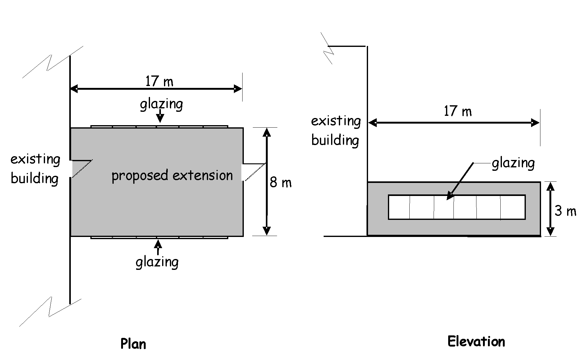
6.B.2 Proposed extension
From the information in 6.B.1 the rate of heat loss from the proposed extension is then calculated as follows:
Table 6.9. Proposed extension heat loss calculation
| Exposed Element | Exposed surface area (m2) | U-value (W/m2 K) | Rate of heat loss (W/K) |
|---|---|---|---|
| External wall | 126-63 = 63 | x 0.22 = | 13.86 |
| Roof | 136.0 | x 0.16 = | 21.76 |
| Floor | 136.0 | x 0.22 = | 29.92 |
| External Door | 3.0 | x 1.8 = | 5.4 |
| Window | 2 of (15x2m) = 60.0 | x 1.8 = | 108 |
| Roof-light | Not applicable | ||
| Total rate of heat loss | = | 178.94 |
6.B.3 'Notional extension'
The rate of heat loss from the notional extension is then calculated as follows:
Table 6.10. Notional extension heat loss calculation
| Exposed Element | Exposed surface area (m2) | U-value (W/m2 K) | Rate of heat loss (W/K) |
|---|---|---|---|
| External wall | 126 - 50.4 = 75.6 | x 0.25 = | 18.90 |
| Roof | 136 - 27.2 =108.8 | x 0.15 = | 16.32 |
| Floor | 136 | x 0.20 = | 27.20 |
| Window + Ext. Door | 50.4 (40%) | x 1.6 = | 80.64 |
| Roof-light | 27.2 (20%) | x 1.6 = | 43.52 |
| Total rate of heat loss | = | 186.58 |
6.B.4 The comparison
The rate of heat loss from the proposed extension (178.94) is less than that from the ‘notional extension’ (186.58). Proposals will comply.
Annex 6.C Energy performance of modular and portable buildings
#Source page 102
6.C.0 Introduction
Modular and portable buildings are prefabricated buildings which are designed for delivery to site as sub-assemblies, connected together and completed on site. These buildings can be disassembled into their sub-assemblies when no longer required and transported to another location and reassembled.
Sub-assemblies are clearly identifiable elements manufactured from a number of components but not the components or raw materials themselves. They can be single or multiple volumetric modules or external wall pack modules.
An alternative compliance route is provided to recognise both the common manufacturing base for UK sub-assemblies and the benefits reuse of existing sub-assemblies offers in respect of embodied energy savings (subject to a specified minimum performance).
For the purpose of this guidance, a modular or portable building is defined as a building which has more than 70% of its external envelope created from sub-assemblies. Sub-assemblies can be manufactured and supplied to order, obtained from a centrally held stock or from the disassembly of existing modular buildings on other premises.
This annex provides guidance and offers an alternate means of meeting Standards 6.1 and 6.2, where a building is categorised as a modular or portable building. Reference should be made to the main text within Section 6 (Energy) for application of Standards 6.3 to 6.10.
Note that, where the intended life of such a building is less than 2 years or the building is a stand-alone building having an area less than 50m2, Standard 6.1 does not apply.
6.C.1 Compliance flowchart
The following flowchart will assist designers and verifiers to determine the measures which should be applied to a modular or portable building to demonstrate compliance with Standards 6.1 and 6.2.
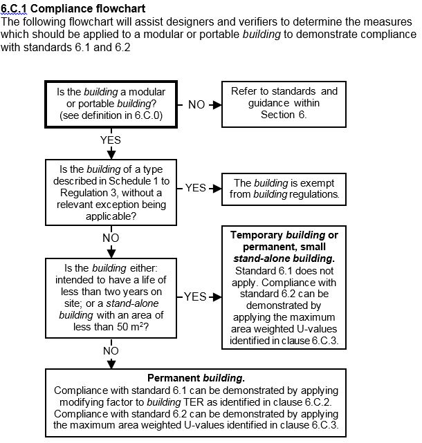
6.C.2 Determining the Target Emissions Rate for permanent modular and portable buildings
To enable the continued use of existing stocks of building modules and sub-assemblies, subject to fabric insulation meeting the U-values noted in clause 6.C.3, a modifying factor can be applied to increase the Target Emissions Rating (TER) for the building. Calculate TER as noted in guidance to Standard 6.1 and apply the relevant modifying factor from the table below to give the permitted emissions rate for the modular or portable building.
Table 6.11. TER Modification
| Date of manufacture of module/sub-assemblies | TER modifying factor |
|---|---|
| after 1 October 2015 | 1.00 |
| 1 October 2010 – 30 September 2015 | 1.75 |
| Prior to 1 October 2010 | 2.50 |
6.C.3 Fabric U-values for modular and portable buildings
For modular or portable buildings, reference should be made to the guidance provided under Standard 6.2, with the exception of area weighted average U-values for a new building or an extension to an existing building. These should be in accordance with the values set out in the table below, in substitution for the corresponding values within tables to clauses 6.2.1 and 6.2.11.
Table 6.12. Maximum area weighted average U-values for building elements of the insulation envelope
Notes:
1.This column should also be used for buildings, including extensions, with an intended life of less than two years.
Annex 6.D Improvement to the energy performance of existing building services when carrying out building work
#Source page 103
6.D.0 Introduction
Scottish Ministers have powers under section 25 of the Building (Scotland) Act 2003 to make a Direction to local authorities where they consider that buildings of any description to which building regulations apply ought to comply with a provision of the regulations.
This power is now exercised to direct local authorities to secure improvement to the energy performance of existing non-domestic buildings. The Direction to local authorities, which enable the following measures, is published on the Building Standards Division website.
6.D.1 Application of Direction
Made under section 25 of the Act, the effect of ‘The Building (Scotland) Act 2003 Improvement to the Performance of Fixed Building Services for Existing Non-Domestic Buildings Direction 2010’ http://www.gov.scot/Topics/Built-Environment/Building/Building-standards/publications/pubverletts/cel1102 is to introduce a requirement to make proportionate and cost-effective improvements to the energy performance of existing fixed building services when proposing new work to an existing non-domestic building.
For the Direction to apply, the following three conditions must be met. The proposed new work (alteration or extension) must:
a.be of a scope that would require an application for building warrant (to enable verification of proposals), and
b.have an estimated value of works, excluding improvement works, of £50,000 or more (to avoid a disproportionate administrative burden on smaller works), and
c.include work to provide completely new fixed building services or to alter or extend the capacity of existing fixed building services to which Standards 6.3, 6.4, 6.5 or 6.6 apply (to enable improvement without the need to engage additional contracting expertise).
If any of the above are not applicable, improvement of existing building services is not required to demonstrate compliance with Standards 6.3 to 6.6.
Where these three conditions are met, there are also specific exceptions to the need to carry out improvement work. These are:
•the Direction is not applied to proposed works which are primarily to improve the carbon or energy performance of an existing building (as the intent of the Direction is already met by such work), or
•existing fixed building services which already meet specific provisions within building regulations applicable since 4 March 2002 need not be improved further (see clause 6.D.7 for further information). This exclusion does not apply to replacement of boilers or existing air-conditioning chiller units as improvement is based on the age of the current installation, not a specified performance standard.
Reference can be made to the application checklist (Table 1) below, which outlines the key questions in the assessment and verification of this process.
6.D.2 Scope of improvements (types of installations which should be assessed)
Applicants should assess the potential for cost-effective improvement in the following areas, each of which is addressed in guidance on compliance to Standards 6.3, 6.4, 6.5 or 6.6 within the 2015 Non-domestic Technical Handbook:
1.upgrading of heating controls and system components (Standard 6.3)
2.upgrading of insulation to hot water storage vessels (Standard 6.4)
3.upgrading of lighting controls and luminaires (Standard 6.5)
4.upgrading of ventilation or cooling controls or system components (Standard 6.6)
5.replacement of existing boiler, if more than 15 years old (Standard 6.3)
6.replacement of existing air-conditioning chiller units, if more than 10 years old (Standard 6.6).
Assessment need only consider the types of fixed building services within the existing building that also form part of proposed works (for example, if no water services or plumbing element under proposed works, there is no need to consider improvement to insulation of vessels and work to circulatory elements to wet heating systems). The intent of this is to avoid the need to engage specialist contractors that are not already involved in a project. However, the applicant may broaden the scope of improvements considered if they choose to (for example, where the applicant considers such improvements to be more relevant to the building in question).
6.D.3 Extent of improvement required (assessing cost and practicality)
Improvement should be proportionate to the extent of proposed works. It is recommended that the cost of improvement works should amount to approximately 5% of the cost of proposed work. In this respect, assessment should be based upon cost of carrying out improvement works, exclude any design or consultancy fees. Where proposed improvements amount to less than this percentage, the applicant should, in scheduling the assessment process, provide evidence to support any reduced level of improvement.
It is the intent that improvement works proposed should be cost-effective, with a short to medium payback period. Assessment need only consider improvements that, when combined, have a payback period of five years or less. The exception to this is the replacement of a boiler or chiller unit, where near the end of its useful life, as there will be additional cost benefit where replacing such equipment as part of more extensive works.
The cost of any improvement works should be included in the estimated value of works used to determine the level of building warrant fee. The value of improvement works and proposed works should be identified separately to allow the proportion of improvement works to be verified.
Work to improve fixed building services should be neither overly disruptive to the operation of the existing building nor require costly or extensive intervention to the building fabric. However, it is recognised that work chosen by the applicant (see clause 6.D.4) may be of such a nature. Where such enabling work is required, it should not be counted as part of the cost of improvement work.
6.D.4 Assessment by applicant
To deliver improvements that are both cost-effective and relevant to the building being assessed, the types of improvement taken forward should be determined by the person responsible for the building (the relevant person/applicant) in consultation with any appointed agent or consultant. Recognising the complexity of the existing building and its systems, assessment should be carried out by persons with the necessary expertise to identify and assess cost-effective and energy efficient improvement.
The intent of the Direction is to deliver cost-effective improvement to the performance of the existing building services. Applicants should be aware that it is therefore in their best interests for existing fixed building services to be examined and assessed, to enable the most effective and beneficial improvements to be identified for consideration.
As noted in clause 6.D.2, whilst specific fixed building service issues are identified, the applicant may propose alternative improvements where they consider these more relevant to the building and can demonstrate that such improvement will deliver broadly equivalent benefit.
Where an Energy Performance Certificate or similar assessment exists for the building, it would be good practice to check any recommendations on existing fixed building services amongst the cost-effective improvements already identified.
For buildings with air conditioning systems, applicants should be aware of the need for inspection of systems over 12kW under regulation 17 of the Building (Scotland) Regulations 2004 and, where applicable, should consider instructing such an inspection where such systems are present. Information from this report will assist in assessing potential improvement to such systems under this Direction.
To maximize benefit to the building, improvements should meet current performance levels recommended in the guidance to Standards 6.3, 6.4, 6.5 and 6.6 where this is reasonably practicable. Where not reasonably practicable, for technical reasons or for reasons of cost or level of disruption to the building, improvement should still be made to the extent that can be achieved. The applicant should take advice on the impact which a lower level of improvement may have on the cost effectiveness of such work and may choose to not make such improvements where payback periods are longer than five years. The case for this should be presented to the verifier.
6.D.5 Review by verifier
The primary role of the verifier is to check that the process outlined above is observed and that proposed improvements to existing building services are of a scale appropriate to the proposed works or, if not, that substantiation for a reduced level of improvement is provided and is justifiable.
Whilst the verifier may question the extent of proposals and request further evidence to support such enquiries, it is not expected that they should direct the types of improvement which are to be carried out for a particular case.
On acceptance of proposals by the verifier, works arising under this Direction are subject to the same process as all other works requiring a building warrant, where the responsibility of the relevant person/applicant is to carry out works in accordance with the issued building warrant and the requirements of the building regulations in general. The verifier will make reasonable enquiry to establish this, prior to accepting a completion certificate.
6.D.6 The role of the Local Authority
Due to the checking integral to the building warrant process, the local authority should generally have no direct role in this process other than as verifier. However, under section 25 of the Act, the local authority may serve a building regulations compliance notice on the building owner, if the improvement work is not carried out. Where the building owner fails to comply with the notice they are guilty of an offence.
However, it should be noted that, if none of the proposed building warrant work is carried out on the building, no improvement work to existing fixed building services need be carried either.
6.D.7 Supplementary information - Exclusion by compliance with previous standards
The performance of components in installations less than 13 years old (post 4 March 2002) need not be improved further where the minimum performance meets levels set within building regulations. The intent of this limitation is to avoid replacement of elements where installations are both recent and relatively energy efficient as this will generally be less cost-effective.
Applicants should note that, as a wider range of building services issues are now addressed within building regulations (an example in 2010 being the introduction of a minimum efficiency for circulators and pumps), it will be necessary to measure performance of some elements against the current edition of the standards, where a level of performance is not identified in previous editions of the building regulations.
Table 6.13 Process checklist
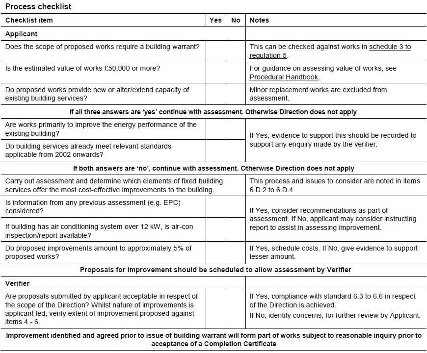
6.D.8 Examples of the process
Example 1
A primary school building, completed in 2000 is being extended to acquire a new staff room. The estimated value of the new work is £50,000. Proposed works include power, lighting, heating and ventilations systems. The capacity of the existing boilers is sufficient to cater for the heating and hot water requirements of the extension. The building already has an EPC which offers recommendations for cost-effective improvement.
After further assessment of the fixed building services in the existing school, the following improvement measures are identified:
•Installation of variable speed drives (VSDs) to the heating system at a cost of £1,800, with annual fuel cost savings of £244 giving a payback period of 7 years.
•Installation of T5 retrofit kits to general lighting at a cost of £700, with annual fuel cost savings of £200 giving a payback period of 3.5 years.
•Installation of lighting daylight sensors at a cost of £2,400, with annual fuel cost savings of £777 giving a payback period of 3 years.
The third option (installation of the daylight sensors) has a short payback period and a higher annual fuel cost saving which may make it the preferred option in isolation, if there were no preference for the type of improvement to be carried out in the existing building.
The combined cost of the two first options is £2,500, with a total annual fuel saving of £488 and a (combined) 5.6 year payback and therefore could qualify if the slightly long payback period is acceptable.
In this case, the building owner is advised that the saving from combining daylight sensors and T5 retrofit would be reduced (as sensors would act to improve a lighting load already reduced by the T5 retrofit) and, having experienced increased heating bills over recent years, elects to improve the performance of the heating system instead of installing sensors. On that basis, the first two improvement options, which constitute around 5% of the proposed value of works, are scheduled as part of the submission to the verifier.
Example 2
A primary health care building, completed in 2001, is extended to provide a café at a cost of £55,000. The existing building services are to be extended to supply the new café. The building already has an EPC which offers recommendations for cost-effective improvement. The building contains an air conditioning system over 12kW and an inspection of the system and report was prepared previously. The report includes some minor recommendations that will improve performance.
Following on from further assessment of the fixed building services in the existing building, the following improvement measures are identified:
•Installation of T5 retrofit kits to general lighting at a cost of £3,900, with annual fuel cost savings of £493 giving a payback period of 8 years
•Replacing GLS with CFL lighting at a cost of £2,200, with annual fuel cost savings of £3,250 giving a payback period of less than 1 year
•Installation of variable speed drives (VSDs) to the heating system at a cost of £2,300, with annual fuel cost savings of £59 giving a payback period of 40 years.
The first option (installation of T5 retrofit kits) is above the 5% cost and the payback period (in isolation) is long. The third option (installation of variable speed drives), while within the identified 5% cost margin, has an unrealistically long payback period which would not make it a suitable choice for improvement.
The remaining improvement item has a short payback period and amounts to less than 5% of the proposed value of works. The recommendations to improve the air conditioning systems are low cost but would contribute to assessment under the Direction.
The building owners choose to implement the second option (replacing GLS with CFL) which has a short payback period and a high annual fuel cost saving, even though the initial cost is below the identified 5% works cost. They also identify improvement to the air conditioning system and the small cost this incurs. As works remain below the identified 5% works cost, evidence is provided to show that no other cost-effective improvements are applicable to the building. Proposed work and evidence of further assessment carried out are scheduled as part of the submission to the verifier.
Annex 6.E - Consideration of High-Efficiency Alternative Systems in New Buildings
#Source page 104
6.E.0 Introduction
On 9 January 2013, a new requirement within building regulations was introduced in response to Article 6 (new buildings) of Directive 2010/31/EU on the Energy Performance of Buildings -
Article 6 - New buildings
1.Member States shall take the necessary measures to ensure that new buildings meet the minimum energy performance requirements set in accordance with Article 4. For new buildings, Member States shall ensure that, before construction starts, the technical, environmental and economic feasibility of high-efficiency alternative systems such as those listed below, if available, is considered and taken into account:
2.Member States shall ensure that the analysis of alternative systems referred to in paragraph 1 is documented and available for verification purposes.
3.That analysis of alternative systems may be carried out for individual buildings or for groups of similar buildings or for common typologies of buildings in the same area. As far as collective heating and cooling systems are concerned, the analysis may be carried out for all buildings connected to the system in the same area.
Accordingly, a statement on how these technologies were considered in arriving at the solution within a building warrant submission should accompany each application for building warrant for a new building made on or after 9 January 2013.
This is relevant to systems specified in relation to Standard 6.3 (heating systems) and, where mechanical cooling is proposed, Standard 6.6 (mechanical ventilation and air conditioning) and also to use of low or zero carbon generating technologies which contribute to meeting emissions targets set under Standard 6.1 (carbon dioxide emissions).
6.E.1 Implications for design
This requirement has no direct implications for the design, specification and construction of new buildings and the functional standards and guidance applicable to heating and cooling systems were unchanged within the Technical Handbooks.
Applicants are not required to use the described technologies. The purpose of this article of the Directive is to encourage awareness and consideration of such solutions.
Whilst new buildings do not have to incorporate such technologies, the challenging standards set under Standard 6.1 (carbon dioxide emissions) do mean that they are a more common part of design solutions in energy efficient, low carbon buildings. For example, an element of PV is present in the TER calculation for new non-domestic buildings.
This means that a range of ‘high-efficiency alternative systems’ will be considered as a matter of course as part of the design process for new non-domestic buildings. This process should not therefore generate a separate and detailed options analysis but will simply record the key outcomes of discussions on this topic during the design process.
6.E.2 Process
When submitting a building warrant, applicants should include a short design statement identifying how the technologies identified in the Directive were discussed and considered as options during the design process and the outcome of that process as shown in submitted proposals.
These technologies include, but need not be limited to:
•decentralised energy supply systems (technologies that do not rely directly on the high- voltage electricity transmission network or gas grid) based on energy from renewable sources
•cogeneration - e.g. combined heat and power (CHP)
•district or block heating or cooling - including partial or full use of renewable energy sources, and
•heat pump technologies
There is no prescribed format or standard form for this exercise but the statement should include at least the following elements.
•Applicant – name, address and contact details
•Duly authorised Agent (if any) – name, address and contact details
•Owner (only if different from applicant) – name, address and contact details
•Location of building or site to which the application relates – address & post code (if known)
•Proposed use of building
All the above information should be as recorded on the building warrant application form, plus
•In providing solutions which meet Standards 6.1 (carbon dioxide emissions), 6.3 (heating system) and 6.6 (mechanical ventilation and air conditioning), is use of high-efficiency alternative systems specified? (if yes, list solutions used)
•If such systems are present, main reasons influencing the decision to use?
•If such systems not used, main reasons influencing the decision to not adopt options?
Analysis may be as concise or as comprehensive as the applicant or their agent consider to be appropriate to the level of discussion that occurred and type and complexity of the project.
A single assessment can be provided with each building warrant though the assessment may have to include separate analysis sections where buildings are different in form or use. Article 6(3) clearly notes that “analysis of alternative systems may be carried out for individual buildings or for groups of similar buildings or for common typologies of buildings in the same area”.
Once submitted, the statement is retained with other building warrant information as a document of record. The verifier is only required to record receipt of the statement and takes no action in respect of the content.
7.0 Introduction
#Source page 105
7.0.1 Background
Sustainable development has been defined as meeting “the needs of the present without compromising the ability of future generations to meet their own needs” by the Brundtland Commission of the United Nations in 1983. It follows that the process of sustainable development and the quality of ‘sustainability’ to aspire to within the built environment should account for:
•social, economic and environmental factors
•the potential for long-term maintenance of human well-being in and around buildings
•the well-being of the natural world and the responsible use of natural resources, without destroying the ecological balance of the area where these resources originate or are processed, and
•the ability for the built environment to be maintained.
The Building (Scotland) Act 2003 allows Scottish Ministers to regulate for the purpose of furthering the achievement of sustainable development. In Scotland, sustainability is embedded into the building regulations for all new buildings, rather than reference being made to new buildings achieving levels within a voluntary system. Since 2005, progress has been made by strengthening the standards on, for example, energy efficiency and accessibility for all new buildings so they are comparable with the best in Europe.
Whilst the standards within Sections 1 - 6 of the 2013 Technical Handbooks deliver a level of sustainability in a number of areas such as energy and surface water drainage, there is always the possibility of going beyond the minimum standard. Scottish Ministers consider that it is not practicable at this time to require every building to incorporate higher performance standards or further sustainability measures. However, developers may wish to gain recognition for building to higher standards. Additionally, organisations such as planning authorities or funding bodies may choose to make constructing to a higher level of sustainability a condition of approval or funding.
Defining higher standards to measure sustainability will enable higher quality buildings to be created and for such benefits to be formally recognised. The continued development of Section 7 is the next step in encouraging the sustainable design and construction of all new buildings within a broader context of sustainable development. Further reductions in carbon dioxide (CO2) emissions from new buildings will also assist in meeting targets within the Climate Change (Scotland) Act 2009.
On 1st of May 2011, Sustainability labelling was introduced to the Scottish Building Standards through the Building (Scotland) Act 2003 which allows Ministers to make building regulations for the purpose of furthering the achievement of sustainable development. Applicable to all new buildings, the principles build upon the degree of sustainability already embedded within the building regulations.
7.0.2 Aims
The aim of the standard in Section 7 is to:
•recognise the level of sustainability already achieved by the building regulations. By setting the 2013 Standards as the benchmark level, credit is given to meeting the standards within Sections 1 - 6 of the building regulations. This will emphasise that a degree of sustainable design and construction is not a niche market but must be achieved in all new buildings
•encourage more demanding sustainability standards through enhanced upper levels
•encourage consistency between planning authorities that use supplementary guidance to promote higher measures of sustainable construction in their geographical areas. By making reference to this standard, local aspirations can be met by selection of clear national benchmarks. Levels of sustainability have been defined that must include a low or zero carbon generating technology, with reference to Section 72 of the Climate Change (Scotland) Act 2009.
7.0.3 Scope
Measures on sustainability are broadly related to the built form, but some matters that are associated with sustainable development such as location and transport cannot be adequately delivered by the building standards system.
Whilst recognising the complexities and variety of non-domestic building types it is anticipated that Section 7, Sustainability will be extended in future for all non-domestic buildings where criteria is defined and verifiable via the building standards system.
At present only the aspect of carbon dioxide emissions is defined within the non-domestic sustainability standard for all non-domestic buildings, other than schools. Sustainability has been fully developed for school buildings which helps act as a pathfinder for further coverage of non-domestic buildings.
The scope of the measures for schools can be divided into the following sets:
•Climate change, energy efficiency, and resource use - will promote the more efficient use of energy, fuel and water in buildings. Encouragement of efficient land use by minimising the impact of building development through enhancing or protecting biodiversity. Reducing water use will reduce the energy consumed and the carbon emissions associated with distributing, processing and heating of water. It is also important that building occupants have the opportunity to understand how their behaviour can reduce use of these resources.
•Well-being - buildings should be designed to accommodate flexibility, for users. Aspects of design for improved well-being, such as enhancing natural daylight, addressing acoustics, and providing access to considered outdoor spaces, should be encouraged for all new schools.
There are areas currently considered inappropriate for inclusion in the optional upper levels for new buildings due to the complexity of some subjects related to building design and construction, such as material sourcing and embodied energy. However the Sullivan Report ('A Low Carbon Building Standards Strategy for Scotland'; published by Scottish Ministers in 2007) recommends total-life zero carbon buildings by 2030. This section can respond in due course to the growing relative importance of embodied energy as the performance of new buildings improves further. At present these areas are outside the scope of this standard. References to external examples of guidance that allow appraisal of local or ethical construction material sourcing, embodied energy and use of recycled materials are the BRE's Green Guide to Specification (www.bre.co.uk) and the materials section on www.greenspec.co.uk.
Schools in particular occupy a central place within a community or neighbourhood. Therefore the concept of a ‘sustainable school’ as a whole will reach out beyond the site boundary and include better and safer active travel routes to and from a school. It is clear that location is outwith the remit of building standards but this part of sustainable design is addressed in Scottish planning policy. The planning document ‘Designing Streets’ contains guidance that should be applied when the connections between schools and the places they inhabit are being considered and designed.
7.0.4 Explanation of terms
Aspect is a term used for a subject area of sustainability. Due to the coverage of building standards and the position of the warrant process in the overall development process, aspects covering resource use and performance are more prominent in this standard. Examples of aspects named and defined in this standard for school buildings containing classrooms are:
•Water efficiency
•Well-being, and
•Material use and waste
Level is a term used as a banding, where all the aspects of sustainability have reached a certain cut-off point. Upper levels in some aspects, whether defined now or still to be defined, may become absorbed into guidance in Sections 1 - 6 to meet revised mandatory functional standards following future reviews of these sections. However, they should not be seen as predictions because the process for review of these sections are independent of Section 7.
Classrooms is a term used to cover general teaching rooms, and other educational spaces such as sports halls, swimming pools, laboratories, workshops, music studios, drama and dance spaces, art classrooms, digital technology accommodation, atria, break out areas, communal spaces and library spaces.
Ancillary spaces is the term used to cover spaces such as receptions, staff rooms, corridors, administrative offices, medical and facility management rooms, and toilets.
Green roof is the roof of a building that is partially or completely covered with vegetation, planted over a waterproofing membrane.
Living wall is the wall of a building, that is partially or completely covered with vegetation, either growing directly on a wall or, as part of specially designed wall.
7.0.5 Latest changes
The following change has been introduced since October 2013:
•Standard 7.1 - amendments have been made to guidance with regard to the carbon dioxide (CO2) emissions target within the Silver and Gold level of Sustainability labelling in relation to the CO2 emissions target introduced by the 2015 energy standards.
7.0.6 Relevant legislation
The Climate Change (Scotland) Act 2009 introduced clause 3F into the Town and Country Planning (Scotland) Act 1997. This places an obligation on local authorities within their development plans to avoid a specified and rising proportion of greenhouse gases by use of low and zero carbon generating technologies. Some of the levels in this standard could be referred to by local authorities when setting local policy in response to this legislation.
The EU Renewable Energy Directive 2009/28/EC states that by December 2014 Member States shall, in their building regulations and codes or by other means with equivalent effect, where appropriate, require the use of minimum levels of energy from renewable sources in new buildings and in existing buildings that are subject to major renovation.
7.0.7 Retrospective application
Scottish Ministers have powers under Section 25 of the Building (Scotland) Act 2003 to make a Direction to local authorities where they consider that buildings of any description to which building regulations apply, ought to comply with a provision of the regulations.
This power has been used to direct local authorities to apply Section 7 to buildings that have been assessed by verifiers. This would only be relevant for buildings that met Sections 1- 6, that have been in force since October 2010 and where, an applicant seeks the recognition that a specified level of sustainability on a label offers. Directions to local authorities, which enable the following measures, are published on the Building Standards Division website.
7.0.8 Certification
Scottish Ministers can, under Section 7 of the Building (Scotland) Act 2003, approve schemes for the certification of design or construction for compliance with the mandatory functional standards. Such schemes are approved on the basis that the procedures adopted by the scheme will take account of the need to co-ordinate the work of various designers and specialist contractors. Individuals approved to provide certification services under the scheme are assessed to make sure that they have the qualifications, skills and experience to certify compliance for the work covered by the scope of the scheme. Checking procedures adopted by Approved Certifiers will deliver design or installation reliability in accordance with legislation.
7.0.9 Other sustainability indicators
Other tools to assess a level of sustainability for new buildings exist and are used in Scotland. These indicators may be selected as appropriate for some developments because they cover issues such as location, orientation on site, or transport that are broader than building regulations can include. Other established indicators place greater emphasis on the sourcing and embodied energy of construction materials, an area flagged up in this section for future review. Other tools could be complementary in an assessment of sustainability but they cannot be used as a method to meet an optional upper level of sustainability within building regulations.
7.1 Statement of sustainability
#Source page 106
Mandatory Standard
| Standard 7.1 Every building must be designed and constructed in such a way that: Limitation: This standard does not apply to: |
7.1.0 Statement of sustainability (sustainability label)
The statement of sustainability (sustainability label, or SL) that includes the level of sustainability achieved must be fixed to the building prior to completion. The sustainability label should be indelibly marked and located in a position that is readily accessible, protected from weather and not easily obscured. A suitable location could be in a plant room or the owner may choose to display the label in a more prominent location. An example of an approved label is given in Annex G. A program to generate such a label that is specific to a building is accessed here: http://www.s7sust.co.uk/.
7.1.1 Levels of sustainability for non-domestic buildings
The award of a sustainability label at the baseline level for all non-domestic buildings (including a school building containing classrooms) should be selected from the following defined within clauses 7.1.3 – 7.1.4:
•Bronze or Bronze Active
The award of a sustainability label at the upper levels would depend upon meeting all 8 aspects. Aspects cannot be traded-off to achieve a score, reinforcing the approach that sustainable outcomes rely on holistic integrated design. The following optional upper levels are only available for school buildings containing classrooms as defined within clauses 7.1.5 – 7.1.9:
•Silver or Silver Active
•Gold
However, all non-domestic buildings that exceed the mandatory standard by achieving the defined upper level criteria in the aspect of carbon dioxide emissions defined within clauses 7.1.6 and 7.1.9 are welcomed. For example, a new building could have a sustainability label at Bronze Active level, which also indicates that a Gold level has been achieved in the aspect of carbon dioxide emissions. This achievement would be clearly reflected on the sustainability label.
7.1.2 Upper levels of sustainability for school buildings
Optional upper levels of sustainability for a school building containing classrooms should be selected from the following, defined within clauses 7.1.4 - 7.1.9:
•Silver or Silver Active
•Gold
The aim is for balance in the setting of upper levels because sustainability is considered in the round rather than focusing on issues of energy or carbon emissions. Reaching upper levels should be a valid target for any new development, regardless of size or location. Generally, levels have been set to avoid individual aspects that could upset applications which might otherwise meet all of the other aspects of sustainability.
The first optional upper level ‘Silver’ offers substantial benefits in a range of sustainability aspects which should be achievable by most new schools. The second optional upper level ‘Gold’ is a more demanding target, initially aimed at those intent on pursuing best practice.
School buildings that exceed a Gold sustainability level are also welcomed. A third upper level called 'Platinum' has been reserved for further recognition within the building standards system. At present, only the aspect of carbon dioxide emissions has been defined for this level.
School buildings that exceed Bronze, Bronze Active, Silver, Silver Active or Gold levels by achieving a higher level criteria in one or more of the aspects are welcome and reflected on the sustainability label. However, the achievement of the next upper level (Platinum) will only be recognised once all aspects of that particular level have been included. The award of an overall upper level depends upon meeting all aspects rather than allowing trade-offs to achieve a score, reinforcing the fact that sustainable outcomes rely on holistic integrated design.
The specified levels of sustainability in clauses 7.1.3 to 7.1.9 are sets of measures that are transparent to all including verifiers, planners, funding bodies, and building users.
7.1.3 Bronze level
This is the baseline level for sustainability achieved where a non-domestic building, (including a school building containing classrooms) meets the functional standards set out in Sections 1 – 6 of this Handbook.
7.1.4 Bronze Active level
This is the baseline level where a non-domestic building (including a school building containing classrooms) meets the functional standards set out in Sections 1 – 6 of this Handbook, but in addition the non-domestic building includes the use of a low and zero carbon generating technology (LZCGT) in respect of meeting Standard 6.1 within Section 6, Energy. This level is primarily to assist local authorities to meet their obligations under Section 72 of the Climate Change (Scotland) Act 2009 by identifying the use of LZCGT. In this respect, LZCGTs include: wind turbines, water turbines, heat pumps (all varieties), solar thermal panels, photovoltaic panels, combined heat and power units (fired by low emission sources), fuel cells, biomass boilers/stoves and biogas.
7.1.5 Silver level for school buildings containing classrooms
A school building at this first optional upper level should meet all the standards in Sections 1 – 6 that apply to the building for the Bronze level and, in addition, the school building should comply with the Silver level in each of the eight aspects below.
7.1.6 Carbon dioxide emissions only at Silver level for all other non-domestic buildings
All non-domestic buildings at this first optional upper level (in this aspect only) should meet all the standards in Sections 1 – 6 that apply to the building for the Bronze level and in addition, the building should comply with the following aspect:
Aspect Silver level 1: Carbon dioxide emissions
All new non-domestic buildings that meet or exceed the Target Emissions Rate (TER) detailed in Section 6, Energy of this Handbook, will automatically meet the Silver level criteria in respect of CO2 emissions. This is due to the 43% improvement on the 2010 Standards that occurred in October 2015.
Aspect Silver level 2: Energy for thermal comfort and artificial lighting - This aspect only applies to school buildings containing classrooms.
Sustainability in the first instance should encourage natural means for heating, cooling, and ventilating a building. However it is recognised that it is not always possible to achieve this for all new buildings, there will always be the need for some form of artificial lighting, heating systems and mechanical ventilation.
a.artificial lighting control: good levels of natural daylight is encouraged in the well-being aspect, therefore artificial lighting control is addressed as part of the energy aspect. All fixed artificial lighting for:
It is not necessary for this to apply to either emergency lighting or specialist process lighting. An example of specialist process lighting is stage spotlights.
Automatically controlled presence or absence detection should not be used where this may cause a hazard or inconvenience (e.g. in an accessible toilet, changing places toilet or medical room).
b.thermal comfort control: in Scotland, the heating season is potentially long, often 8-9 months of the year and therefore heating provision within a building is a key consideration. Schools designed and constructed to meet Section 6, Energy will have a thermally efficient external envelope and benefit from intuitive controls. For all fixed services that use energy for the purpose of providing thermal comfort should have:
*A dead band thermostat has a function where no conditioning occurs between a specific temperature range, proposals include energy required for fans.
c.effective control of solar gain: to minimise the potential for summertime overheating all roof lights and south facing window openings should include measures for the effective control of solar gain. Example options are provided in Annex A.
This does not apply to areas of glazing that form part of an unheated room or space.
Aspect Silver level 3: Water Efficiency - This aspect only applies to school buildings containing classrooms.
a.water use efficiency: for the most part, Scotland does not suffer from water shortages. However, a significant proportion of energy is used for the abstraction and disposal of water as well as the heating of water for health and hygiene within a school. Therefore addressing water use efficiency is to reduce the energy used throughout the water cycle. Enhanced or additional fittings should be provided as follows:
A delayed-action inlet valve for siphon flush toilets saves water by preventing the cistern refilling until the flush cycle is completed.
When specifying water efficient fittings consideration should be given to the operational flow rates that some heating or hot water appliances, such as combination boilers, or point of use or instantaneous water needs to activate their water heating function.
When installing low volume flush WCs, the pipe diameter and gradient inter-relationship is critical in order that the new and any existing sections of the drain are self-cleansing.
b.energy for water heating: at least 10% of the annual energy demand for water heating required should be from heat recovery and/or renewable sources with little or no associated fuel costs (e.g. solar thermal water heating and associated storage).
In areas where a large amount of energy is required for hot water the generating equipment and storage vessels should be situated as near as conveniently possible to where the majority of hot water is used.
A school building is recognised as having a dispersed and occasional hot water use. So to prevent high standing losses for Domestic Hot Water (DHW) localised equipment should be used.
Point of use/instantaneous electrically heated water is a system where the water is supplied to the draw off points from a device, in which water is heated by an electric element(s), and should be considered where the use of hot water is remote from the main hot water heating systems.
Where a system cannot achieve an efficiency of 50% then point of use or instantaneous hot water systems should be used.
Point of use electrically heated water system should comply with BS EN 60335-2-21. Instantaneous electrically heated water system should comply with BS EN 60335-2-35: 2003.
c.surface water management: the design and construction of school roofs, and hard surfaces should include one or more of the following Sustainable Urban Drainage (SUD) measures capable of controlling 50% capacity of the predicted rainfall for the overall site and also enhance the biodiversity value of the site:
Designers may have to undertake a risk assessment to manage or alleviate any health and safety concerns that may arise from the inclusion of a SUD measure.
Where surface water drainage is included as part of an existing community SUDS, the building can utilise an existing system where capacity is available.
Areas of green roofs, living walls and attenuation ponds included as part of the source control SUDS option may be included as part of the calculation for the overall area dedicated for natural habitat outlined in Aspect 4 Biodiversity.
Aspect Silver level 4: Biodiversity - This aspect only applies to school buildings containing classrooms.
Biodiversity is highly valued in the school estate. The reasons for inclusion is to minimise the impact of a building development on an existing site, to enhance biodiversity and encourage natural habitats on developments as well as increasing the opportunity for pupils to have greater contact with nature.
a.allotment: provision of a dedicated area set aside for use as an allotment with an area of at least 5% of the building footprint. The allotment area should contain the following:
b.natural boundary: 25% length of the site boundary that does not form part of the building elevation to be defined/augmented by planting or natural features (natural features can include attenuation ponds, woodland, natural habitats and allotments).
c.natural habitat or native woodland area: provision of a dedicated area of approximately 15% of the overall site area capable of evolving into a designated:
d.biodiversity strategy document: provision of an ecological report and a bespoke user guide for the school, for use by pupils, teachers and the wider community related to enhancing biodiversity and developing ecological understanding, prepared by a person with appropriate training, knowledge, experience and skill.
An example of bespoke biodiversity user guide and a guidance template to prepare the user guide can be found in Annex B.
Aspect Silver level 5: Well-being - This aspect only applies to school buildings containing classrooms.
a.natural daylight: research has shown that good natural daylight is beneficial to a sense of well-being and has the potential to improve academic performance. Schools are primarily occupied during daylight hours and therefore natural daylighting should be the prime means of lighting a school where available. Good levels of natural daylight also reduces the need for artificial lighting. A minimum average daylight factor (DF) of 3% should be achieved in all classrooms at a working plane.
The reference point for the working plane should be between 500 - 900mm from floor level.
For 75% of classrooms where natural daylight is provided, a uniformity ratio should be achieved in the range of:
•0.3 to 0.4 for vertical areas (e.g. windows)
•0.6 to 0.8 for horizontal areas (e.g. roof lights)
A simplified DF calculation can be found in Annex C.
The guidance given here is written in terms of a applying a simplified calculation. However other calculation tools or techniques may be used (such as daylight calculations used in dynamic simulation modelling or Computer Aided Drawing (CAD) software) provided they are based on one of the following methodologies:
•CIBSE Guide A: Environmental Design
•BS EN 8206-2: 2008
•BRE Digest 309
The benefits of providing natural daylighting generally outweigh the drawbacks. However, there are recognised issues that should be considered when balancing the requirements:
•glare particularly from low level winter sun
•excessive heat gains during summer months
•safe methods of cleaning glass
•maximising natural light while meeting the challenging energy standards where a larger glazed area is used.
b.indoor air quality monitor: good indoor air quality (IAQ) is an important issue for sustainable school design. Ventilation to maintain IAQ contributes to the health, comfort and well-being of the occupants. Although the occupancy levels of a classroom vary throughout the day, the measuring and monitoring of classrooms will make sure that optimum IAQ is maintained whilst maximising the efficiency of a mechanical ventilation system, where it is used.
All teaching classrooms to have a real-time display monitor that measures the CO2 parts per million (ppm) levels, and temperature (deg C) to alert room occupants when the average concentration of CO2 reaches 1500 ppm when measured at 1500mm above floor level.
c.acoustics: background noise can be a significant obstacle to effective listening. Favourable classroom acoustics benefit pupils and teachers alike improving pupils’ well-being and educational performance as well as enhance a school's suitability for alternative uses.
A written design specification, provided by a specialist acoustic consultant to determine appropriate acoustic performance levels for all classrooms which address the following:
•indoor ambient noise levels including noise from building services
•airborne sound insulation between teaching/activity spaces
•airborne sound insulation between circulation spaces and other occupied spaces
•impact sound insulation of floors
•reverberation in teaching and study spaces
•sound absorption in corridors, entrance halls and stairwells
•design of open plan areas (where applicable).
The specialist acoustic report should be prepared by a person with appropriate training, knowledge, experience and skill of school design.
d.room height: to assist designers in meeting the specified natural daylight factors and reduce the likelihood of a classroom having increased CO2 concentrations levels, 80% of all classroom areas should achieve an average minimum floor to ceiling height of 3500mm for secondary schools and 3000mm for a primary school.
Aspect Silver level 6: Flexibility and Adaptability - This aspect only applies to school buildings containing classrooms.
Active travel is an approach to travel and transport that focuses on physical activity walking and cycling. The purpose of the guidance is aimed at accommodating staff, pupils and visitors that walk or cycle to school or participate in outdoor activities, by including facilities such as cycle storage, changing facilities, transition spaces, lockers and dedicated drying spaces.
a.cycle storage Table 7.1. Storage Ratio Primary School Secondary Schools 1 space per 20 staff 1 space per 20 staff 1 space per 20 pupils 1 space per 10 pupils Key cycle storage provisions:
An example of cycle and scooter parking can be found in Annex D.
Accommodating active travel and in particular commuting by cycle may not be appropriate for all schools. (i.e. rural locations where the population is dispersed and routes to the school are not suitable for walking or cycling. Where cycling to school does not form part of an Active Travel Plan a minimum of 2 spaces for visitors not more than 50m from the principal entrance should still be provided.
b.staff active travel facilities: to support active travel and encourage outdoor activity in all weather conditions the following facilities should be provided on a ratio of 1 per 10 cycle storage spaces, or part thereof; and include:
Where reasonably practicable drying spaces should be designed to be passively heated and ventilated.
A dedicated drying space designed to be passively heated should have glazed openings located on one or more of the south, east, or west facing elevations. A dedicated drying space should be designed to be naturally ventilated.
Where the dedicated drying space is not passively heated a heat source should be provided that is independent from the primary heating system and capable of maintaining a temperature of 180C when the outside temperature is -10C and controlled by a time switch.
Where the dedicated drying space is not naturally ventilated, a mechanical extract vent should be provided and have an intermittent capacity of at least 30 l/s (a humidistat at 50-60% relative humidity) or Mechanical Ventilation Heat Recovery (MVHR) controlled on a time switch.
It is recommended that internal linings of a dedicated drying space should be of a suitably hygroscopic (moisture absorbing) material.
Where the drying space is not incorporated within the room with the active travel facilities then access should be directly from the active travel facilities.
Examples of a dedicated drying area are shown in Annex E.
Active travel facilities can be included as part of a greater quota for the overall school (i.e. where sports changing facilities are present within a school). However where changing and showering facilities are located in a separate building contained within the same campus, there should be at least one space provision for changing and showering within each new building.
c.pupil active travel facilities: 1 secure active travel locker per pupil, with a minimum size of 300mm wide, 450mm deep 1200mm high to accommodate active travel equipment i.e. shoes, clothing, helmet, backpack. For primary school pupils the height of the locker can be reduced to not less than 600mm.
d.vehicle parking and drop off areas: ‘shared space’ is a design approach that seeks to change the way streets operate. The principle is aimed at prioritising pedestrians and cyclist movement and reducing the dominance of motor vehicles by removing the traditional regulatory functions and formal demarcation, such as signposting, and kerbing.
Where parking facilities, setting down points and turning circles are provided, these spaces should be designed and constructed to be a level surface with the removal of all kerbs and barriers between footpaths and roads, to encourage shared spaces principles.
Further information on shared space can be found at: Local transport note – shared space https://www.gov.uk/government/publications/shared-space.
e.external teaching space: provide an external structure giving overhead protection from inclement weather with an area not less than 35m2 for primary schools and 45m2 for secondary schools for the purpose of facilitating general teaching activities, external performances or outdoor play.
Aspect Silver level 7: Material use and Waste - This aspect only applies to school buildings containing classrooms.
The collection and sorting of solid waste for recycling is an activity that building users can contribute towards. This should include metal, glass, cardboard and paper, plastic and printer/toner cartridges, as well as food and horticulture waste suitable for composting or collection from a bio digestion facility. It helps balance the technical design focus of many of the other aspects because it is part of an adaptive solution to a sustainable future.
a.recycling of solid waste: a strategy document to be provided as part of the user guide in Aspect 8 which identifies dedicated spaces for the collection and storage of everyday recyclable materials.
A dedicated external storage space to be provided which caters for recyclable materials (including excess food waste that is not composted on site), generated by users of the building during occupation.
The space allocated should have a washable hard surface area to accommodate waste containers required by the waste collection authority. Convenient access to the contents of the container should be provided to allow removal.
The hard surface may be a collection point designated by the waste collection authority where the container can be removed or emptied. If the hard surface is not the collection point then there should be an accessible route along which the container can be transported to the collection point.
The storage area should have provision for washing down and draining into a wastewater drainage system. Gullies should incorporate a trap that maintains a seal even during periods of disuse. Walls and floors should be of an impervious surface that can be washed down easily and hygienically.
Any enclosure for the storage of waste should be designed as to prevent access by vermin unless the waste is to be stored in secure containers with close fitting lids, such as wheeled bins.
Aspect Silver level 8: Optimising Performance - This aspect only applies to school buildings containing classrooms.
a.user information guide: provide guidance for use by the building occupants on the ways in which all classrooms are intended to function (heating cooling, lighting and ventilation) and how to optimise energy performance. This is additional to the written information to be provided for occupants under Section 6 of the Technical Handbooks.
A summary of information to be affixed at the entrance of each classroom to provide guidance to the building user on the ways in which the specific classroom is intended to function (heating, cooling, lighting and ventilation) and how users can optimise the performance.
Information on the scope, format and contents of the guide for occupants can be found in Annex F.
b.resource use displays: install a real-time resource use monitor(s) with the data linked to a visual display located in an easily accessible and readable position at the principal entrance area to the building. For the purpose of teaching, monitoring and recording purposes by pupils staff and the local community that displays energy use for heating, ventilation, cooling, lighting and small power.
7.1.7 Silver Active level
This is the same as the Silver level aspect but, in addition the school includes the use of a low and zero carbon generating technology (LZCGT) in respect of meeting at least one of the aspects: Silver 1, Silver 2 or Silver 3. This level is primarily to assist local authorities to meet their obligations under Section 72 of the Climate Change (Scotland) Act 2009 by identifying the use of LZCGT. In this respect, LZCGTs include: wind turbines, water turbines, heat pumps (all varieties), solar thermal panels, photovoltaic panels, combined heat and power units (fired by low emission sources), fuel cells, biomass boilers/stoves and biogas.
7.1.8 Gold level for school buildings containing classrooms
A school building at this second optional upper level should meet all the standards in Sections 1 – 6 that apply to the building for the Bronze level and in addition the school should comply with the Gold level in each of the eight aspects below.
7.1.9 Carbon dioxide emissions only at Gold level for all other non-domestic buildings
All non-domestic buildings at this first optional upper level (in this aspect only) should meet all the standards in Sections 1 – 6 that apply to the building for the Bronze level and in addition, the building should comply with the following aspects:
Aspect Gold level 1: Carbon dioxide emissions - This aspect applies to all non-domestic buildings.
Under the guidance to Standard 6.1, carbon dioxide emissions (Building Emission Rate) is to be 38% lower than the Target Emission Rate (TER) set by the 2015 Standards.
To establish this, the TER from the NCM calculation should be multiplied by 0.62, to give a revised figure that the BER should not exceed. (This is equivalent to a 64.3% improvement on the 2010 Standards and a 75% improvement on the 2007 Standards).
Aspect Gold level 2: Energy for thermal comfort and artificial lighting - This aspect only applies to school buildings containing classrooms.
a.artificial lighting control: provide as for Aspect Silver 2
b.thermal comfort control: provide as for Aspect Silver 2, including destratification fans in all spaces with a ceiling height greater than 6m
c.effective control of solar gain: provide as for Aspect Silver 2, including all east, and west facing windows
d.building management system (including sequential control, zone control, weather compensation, frost protection, night set back including monitoring and targeting)
e.draught lobby: should be provided to the main entrance of the school building.
A draught lobby is an arrangement of two doors to the principal entrance or exit of a building that reduces unwanted air infiltration. The enclosed space should open into a public circulation area and the door arrangement should be such that a person with a pushchair or similar item is able to close the outer door before opening the inner door. It may be heated or unheated and may provide access to a cloakroom, store or WC.
Aspect Gold level 3: Water Efficiency - This aspect only applies to school buildings containing classrooms.
a.Enhanced or additional fittings should be provided as follows:
A delayed-action inlet valve for siphon flush toilets, saves water by preventing the cistern refilling until the flush cycle is completed.
Where point of use or instantaneous water heating is installed consideration should be given to the flow rates that hot water systems need to activate their water heating function when specifying taps and shower heads with lower flow rates.
When installing low volume flush WCs, the pipe diameter and gradient inter-relationship is critical in order that the new and any existing sections of the drain are self-cleansing.
b.energy for water heating: provide as for Aspect Silver 3, except 50% of the annual energy demand for water heating required should be from heat recovery and/or renewable sources with little or no associated fuel costs (e.g. solar thermal water heating and associated storage).
c.surface water management: provide as for Aspect Silver 3 except the design and construction of the school roofs, and hard surface should be capable of controlling 100% capacity of the predicted rainfall for the overall site from one or more of the Sustainable Urban Drainage measures described in Aspect Silver 3.
Areas of green roof, living walls and attenuation ponds included as part of the source control SUDS options may be included as part of the calculation for the overall area dedicated for natural habitat outlined in Aspect 4 of Biodiversity.
Aspect Gold level 4: Biodiversity - This aspect only applies to school buildings containing classrooms.
a.allotment: provide as for Aspect Silver 4.
b.natural boundary: provide as for Aspect Silver 4, except 50% length of the site boundary that is not part of the building elevation to be defined/augmented by planting or natural features (natural features can include attenuation ponds, woodland, natural habitats and allotments).
c.natural habitat or native woodland area: provide as for Aspect Silver 4, except 30% of the overall site area capable of evolving into a designated:
d.biodiversity strategy document: provide as for Aspect Silver 4.
Aspect Gold level 5: Well-being - This aspect only applies to school buildings containing classrooms.
a.natural daylight: provide as per Aspect Silver 5, except an average daylight factor (DF) of 4% should be achieved in all classrooms at a working plane.
b.indoor air quality monitor: provide as for Aspect Silver 5 and, where a room uses mechanical ventilation as the prime means of ventilating the room, this should be linked to automatic controls to make sure the average concentration of CO2 does not exceed 1500 ppm when measured at 1500mm above floor level.
c.acoustics: a written report and design specification provided by an acoustic consultant that meets the performance standards in Building Bulletin 93: Acoustic design in schools (BB93) for all classrooms. The specialist acoustic report should be prepared by a person with relevant expertise in acoustics for school design.
To assist in making certain that acoustic performance standards are met, acoustic testing of indoor ambient, airborne, and impact noise levels should be undertaken in at least one room in every four of each type of classroom. This should include rooms on the noisiest elevation; measurements should be taken vertically and horizontally between adjacent classrooms.
These classrooms should be finished and unoccupied. It is not intended that measurements should be taken between circulation spaces, entrance halls and stairwells. Measurements should be made when external noise levels are representative of conditions during normal school operation.
Where there is a failure to meet the performance standards in any of the classrooms an additional classroom should be identified and tested. Should the additionally tested classrooms also fail then all of the remaining classrooms must be tested and remedial treatment carried out.
Acoustic testing should be carried out by persons who can demonstrate relevant, recognised expertise in acoustics for sound insulation testing of buildings and carried out in accordance with the methods described in ‘The Good Practice Guide’ for the acoustic testing of schools published by the Association of Noise Consultants.
d.room height: provide as for Aspect Silver 5.
Aspect Gold level 6: Flexibility and Adaptability - This aspect only applies to school buildings containing classrooms.
a.cycle storage Table 7.2. Storage Ratio Primary schools Secondary schools 1 space per 10 staff 1 space per 10 staff 1 space per 10 pupils 1 space per 5 pupils Key cycle storage provisions: provide as for Aspect Silver 6
b.staff facilities for active travel: provide as for Aspect Silver 6
c.pupil facilities for active travel: provide as for Aspect Silver 6
d.vehicle parking and drop off: provide as for Aspect Silver 6
e.external teaching space: provide as for Aspect Silver 6 including the following:
f.accessibility: the principal accessible entrance doors to the building should be provided with an automatic powered opening and closing device as detailed in Section 4, Safety (clauses 4.1.7 and 4.18).
g.Changing Places Toilet (CPT): a CPT is a toilet with a changing facility that is suitable for use by people that have profound and multiple learning disabilities or other disabilities and for whom standard accessible toilets may not be fit for purpose and should be provided for all Secondary Schools which have all of the following facilities:
A typical CPT installation should include the following key elements:
•adequate space (12m2) to allow a user to be assisted by carers
•a minimum ceiling height of 2.4m
•a wall or ceiling mounted tracking hoist
•a centrally placed WC with space either side for the carers
•a height adjustable wash hand basin
•a non-slip floor finish
•a door with a minimum clear opening width of 1m.
In addition to the building related elements, a fully equipped CPT relies on the installation of additional equipment and specialist fittings, such as a height adjustable adult sized changing bench (min 1.8m in length). Further information, including a full specification, can be found at the website of the Changing Places Consortium and BS 8300: 2009.
To be registered on the Changing Places’ national register all new CPTs need to meet the standards specified by the Changing Places Consortium (CPC).
Aspect Gold level 7: Material Use and Waste - This aspect only applies to school buildings containing classrooms.
a.recycling of solid waste: provide as for Aspect Silver 7.
b.construction site waste management plan: by consideration of waste minimisation arising from the built-form, the following information should be recorded:
The quantity of construction waste produced from excavations does not have to be recorded as this is site dependant. However best practice recommends that where possible excavation material should be diverted from landfill.
Likewise it is not possible to reduce demolition waste as this is also dependant on existing site circumstances. It may however be possible to reuse demolition materials in a bid to reduce the amount of new materials required.
Aspect Gold level 8: Optimising Performance - This aspect only applies to school buildings containing classrooms.
a.User Guide: provided as for Aspect Silver 7.
b.Resource use displays: provided as for Aspect Silver 7, including the capability for the information provided from the resource use display to have the data collected and recorded centrally to allow for comparison over a period of time.
7.1.10 Carbon dioxide emissions only at Platinum level for all other non-domestic buildings
All non-domestic buildings at this third optional upper level (in this aspect only) should meet all the standards in Sections 1 – 6 that apply to the building for the Bronze level, and in addition the building should comply with the following aspect:
Aspect Platinum level 1: Carbon dioxide emissions - This aspect only applies to all non-domestic buildings.
Under the guidance to Standard 6.1, the carbon dioxide emissions (Building Emission Rate) is to be 100% lower than the Target Emission Rate set by the 2010 Standards. To establish this, the BER from the NCM calculation should not exceed zero (this net zero carbon equivalent is a 100% improvement on the 2007 Standards).
Aspect Platinum level 2: Energy for thermal comfort and artificial lighting
Not currently defined.
Aspect Platinum level 3: Water Efficiency
Not currently defined.
Aspect Platinum level 4: Biodiversity
Not currently defined.
Aspect Platinum level 5: Well-being
Not currently defined.
Aspect Platinum level 6: Flexibility and Adaptability
Not currently defined.
Aspect Platinum level 7: Material Use and Waste
Not currently defined.
Aspect Platinum level 8: Optimising Performance
Not currently defined.
Annex 7.A Example options of measures for the control of solar gain
#Source page 107
Solar shading should be designed to reduce summer time overheating and allow passive solar gain during winter months. Effective solar shading design should not reduce natural lighting within a room to the extent that artificial lighting is required. External shading devices are the most effective as they deflect solar radiation before it enters the building.
Horizontal devices on south facades provide the most effective shading without compromising natural daylight, however this type of measure is not suitable for east and west facades as the angle of the sun is too low. Vertical fins and adjustable devices such as sliding and rotating shutters are best suited to east and west facades. For optimum indoor thermal comfort designers should consider combining effective solar shading with night time cooling through the use of inward opening hopper windows or vents.
Figure 7.1. Horizontal overhangs
Horizontal overhang or window reveals are best suited for south facing openings, the total shading depth should be around 50% of the window height and extend no greater than 1500mm for optimum effectiveness. Measures can provide up to 75% solar gain reduction.
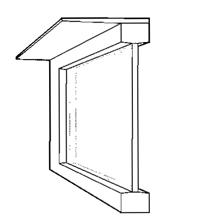
Figure 7.2. Horizontal louvres
Horizontal louvres and shutters (sliding or rotating) combined with a horizontal overhang can be used on south facades. Measures can provide up to 90-95% solar gain reduction.
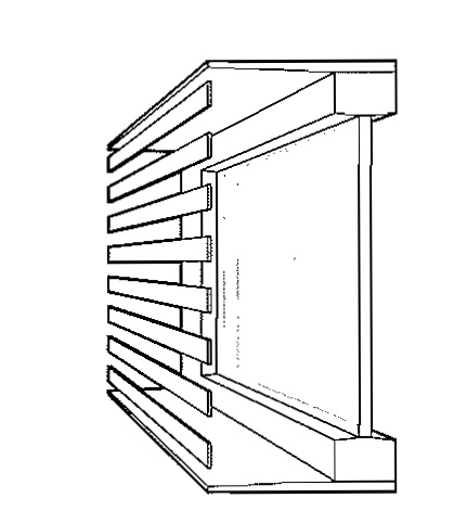
Figure 7.3. Shutters
Shutters (sliding or rotating) can be used on south, east and west facing facades. Lockable shutters allow secure night time cooling and inward opening windows.
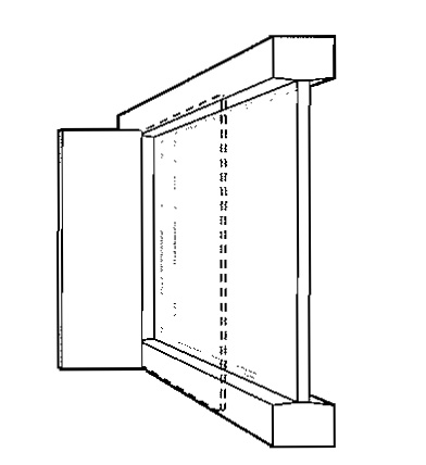
Figure 7.4. Vertical fins
Vertical fins (adjustable or fixed) combine with a horizontal overhang are best suited for east and west facades. Measures can provide up to 85-90% solar gain reduction.
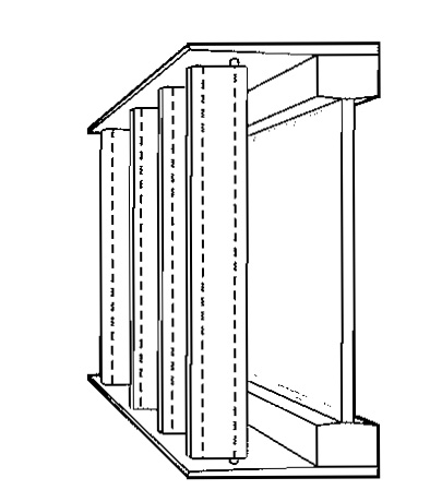
Figure 7.5. Awnings
Awnings or roller shades can be used on south, east and west facades. Measures can provide up to 60-75% solar gain reduction.
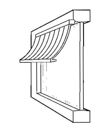
External shading devices should be considered in the first instance. However where external shading devices cannot form part of the external fabric for reasons such as a planning restrictions, internal shading devices such as curtains and blinds can be used. These measures are generally not as effective as external shading devices as they absorb part of the solar radiation within the room or space.
Annex 7.B Supplementary guidance in the aspect of biodiversity
#Source page 108
New developments are not always required to undertake a formal ecological assessment as part of a planning application as the condition/state of the existing site is largely predetermined. However almost all sites will have the potential to enhance their ecological value in some form.
It is proposed that the verification of the biodiversity aspect be carried out in two stages. At building warrant application an appropriately qualified person visits the site and prepares an ecological report on the existing key biodiversity characteristics of the site including:
•ecological overview of the site
•baseline habitat
•plant and animal species to note
•surface water features.
The purpose of the report is not to award the site with an ecological value, but to understand the baseline characteristics of the site and have recommendations that could be included and developed in a bespoke biodiversity strategy guide. The information should also inform the most appropriate locations for:
•allotment
•natural boundary
•natural habitat or woodland area required to meet the biodiversity aspect.
This report should then inform a bespoke biodiversity user guide specific for each school geared towards enhancing biodiversity and promoting ecology, recommendations may include:
•maintenance and development of key areas
•the planting of native species or those with a known attraction or benefit to local wildlife
•the adoption of horticultural good practice (e.g. no, or low use of residual pesticides)
•development of a maintenance plan including avoiding clearance/works at key times of the year (e.g. breeding seasons)
•the proper integration, design and maintenance of SUDS and green roofs, where applicable etc.
A good practice template for preparing a biodiversity guide for new schools and an example bespoke biodiversity guide can be found on the Scottish Government website at http://www.gov.scot/Topics/Built-Environment/Building/Building-standards/publications/pubresearch/researchsustainability.
At the completion stage the applicant should re-submit the bespoke biodiversity guide after review and updating of specified items as necessary.
Annex 7.C Daylight factor calculation
#Source page 109
Average DF% = (52 x M x W) / A
Where:
A = The sum of the area of all room surfaces (ceiling, floor, walls, doors, windows and roof lights), in m2
M = Correction factor for dirt or ease of cleaning, consisting of:
•1.0 for vertical glazing, or
•0.8 for sloping glazing, or
•0.7 for horizontal glazing
W = Glazed area of windows or roof lights, taking account of framing, in m2. Measure glazed panes or measure window area including frames then multiply by:
•0.9 for metal frames (patent glazing), or
•0.8 for metal frames (large pane), or
•0.7 for timber frames (large pane), or
•0.6 for timber frames (smaller pane)
Assume the factors for PVC framed windows are equal to timber.
The angle of visible sky from inside a room has been removed so that the standard is not location dependent.
When designing window apertures it is worth considering that the window area below the working plane does not significantly increase the amount of daylight falling onto the working plane. This is because the light from the lower part of the windows has to bounce off at least two room surfaces before it reaches the working plane.
A room capable of being top lit is the part of the building where roof lights can be used to provide natural daylight, this would include all single-storey buildings or rooms located on the upper most floor of a multi-storey building. Roof lights do not have to be provided where the daylight factor can be achieved from a combination of windows on the vertical plane.
Annex 7.D Example cycle and scooter parking
#Source page 110
A bicycle stand must be capable of allowing the frame of the bicycle to be locked to the rack.
Suggested dimensions:
•All bicycle stands should be permanently fixed to a hard surface or a permanent vertical surface
•Each single stand should have the capacity to allow two bicycles to be locked by the bicycle to the stand
•A minimum distance between stands of 900mm
•A minimum distance of 500mm between stands and any perimeter line/fence
•A minimum distance of 500mm to be available at the front and rear of the stand
•A minimum length of stand to be 700mm
•Height above ground level 750mm
•Wall mounted cycle fixing rings and bars should be fitted between 700-800mm high.
Figure 7.6. Example of cycle and scooter parking
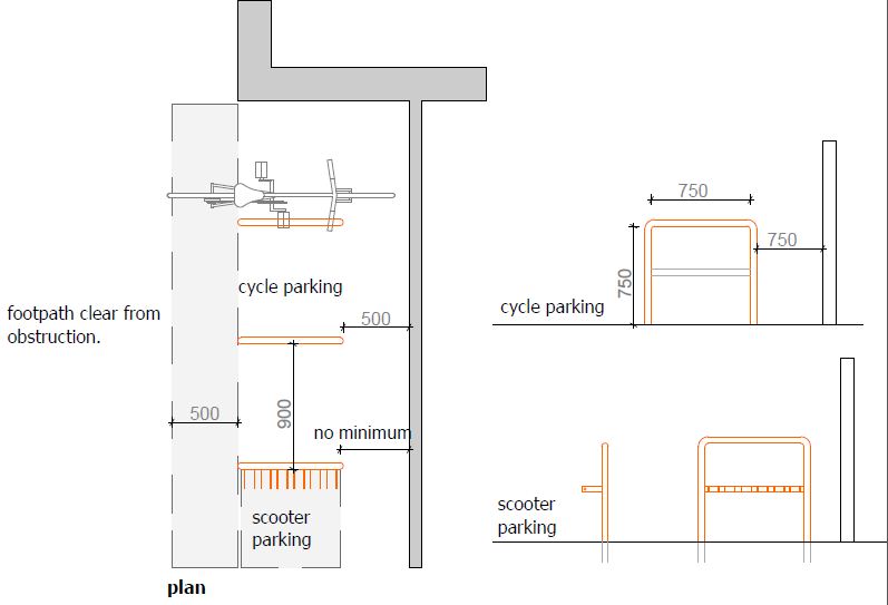
Annex 7.E Example of a dedicated internal drying area
#Source page 111
Suggested minimum dimensions of a dedicated drying space designed to be passively heated and naturally ventilated to provide a total linear hanging length of 7.2m. 2.4m wide 1.1m deep and 2.3m high; or a volume of 6m3.
Figure 7.7. Example of passively heated and ventilated dedicated internal drying space
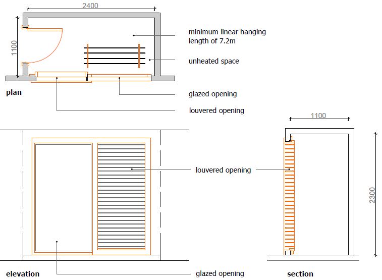
Suggested minimum dimensions of a dedicated drying cupboard with an independent heat source to provide a total linear hanging length of 7.2m. For example 900mm wide x 850mm depth x 2.3m with two rows of four slats or retractable pulleys each 900mm long or a volume of 1.75m3.
Figure 7.8. Example of dedicated mechanically heated and ventilated internal drying space
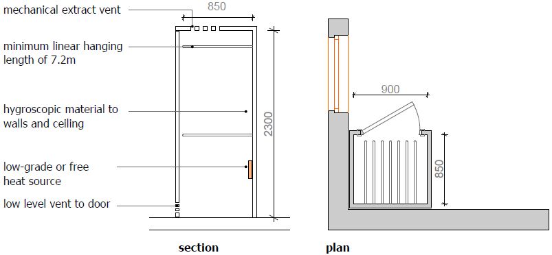
Annex 7.F Supplementary guidance in the aspect of optimising performance
#Source page 112
7.F.0 Introduction
The guide should be produced in 2 stages:
•at building warrant application submit as much information as possible including the floorplan(s), an outline of the construction and building fabric, specified systems or equipment and any other environmental features, and
•re-submit at completion after review and updating of specified items as necessary.
Better design and construction of control mechanisms should make more intuitive buildings and reduce the need for user guidance.
A good practice example of a guide developed for domestic buildings is on the Scottish Government website at www.scotland.gov.uk/bsd.
7.F.1 Scope
The guide should be bespoke to the particular school containing information directly relevant to the design function of the building, as well as identifying strategies for key rooms such as classrooms, sports halls, libraries or community rooms outlining their overall heating lighting and ventilation strategies. This will allow a greater understanding on controlling their internal environment in an efficient manner. It should be tailored to be a concise non-technical ‘User Information Guide’ for school occupants (pupils, teachers and ancillary staff and visitors) on the operation, and environmental performance covering:
•overview of environmental strategies: both passive and active
•energy for heating
•ventilation
•energy for lighting
•water use
•recycling and waste management
•renewable technologies
Do not include unnecessary detail on the operation of the individual elements or systems of technology.
7.F.2 Format
The information within the user information guide should be concise and compact and presented where possible with graphics to aid rapid comprehension. Utilising this approach therefore means it is more likely to be kept available, used for future reference and represented as new pupils are introduced to a school.
The guide should be accessible to all, using diagrams and coloured presentations. Information should be available in digital format to allow it to be made available as a digital booklet and able to be stored online on a central server perhaps to be used as a mobile application, a digital information board or server screen savers or part of a home screen where Wi-Fi is available.
Key classrooms that are likely to be used for community or public functions such as, sports halls, libraries or community rooms should have a permanent display to inform occasional users on how to operate the building effectively.
The emphasis is to provide the information as a digital booklet. Where printed copies are required, the recommended formats should be as a booklet.
7.F.3 Graphics, images and text
The guide should include plans, locating key items of equipment and information only on the systems installed. The format should revolve around simple illustrations following the principle – ‘show don’t tell’. An illustration can be a hand-drawn sketch, a computer image or a photograph. These can be mixed because consistency in style is less important than content. Illustrations do not need to be to scale, but should show relationships and explain things quickly and easily. These guidelines should be followed:
•Use illustration where possible to focus the building user on the equipment that users normally come into contact with (e.g. heating controls and lighting controls)
•Link key components (e.g. lighting controls) to location plan to help the user to make connections between controls and systems quickly
•Images should be labelled
•Avoid non-essential images (e.g. lifestyle image) which can reduce the authority of the document
•Use graphic formats that preserve the sharpness and clarity of lines
•Illustrations should be associated with a legible caption of standard size and colour
•Many people have difficulty understanding plans, so use other images, (e.g. a simple 3D diagram alongside plans to aid comprehension)
•Use colour where possible as an easy way to differentiate categories visually. However readers may be colour blind, so use icons, illustrations and high contrast type
•Digital Text, plans illustrations and diagrams should be scalable to assist people who may have sight difficulties
•Use clear, colour, photographs (well lit, avoid use of flash if possible) or line illustrations of actual installed equipment
•Use engineer’s or manufacturer’s drawings as reference in order to comprehend the system but edit these to remove unnecessary items
•Do not attempt to replace the manufacturer's manuals but refer to them for further information. The main elements or products should be identified with their full names/reference model numbers and links to more information such as manuals or manufacturers websites
•Use plain English avoiding detailed technical descriptions
•Use bullet points where possible
•Avoid jargon and acronyms. If an acronym is necessary define it on first use. (e.g. MVHR (Mechanical Ventilation Heat Recovery system) is used because the acronym is more likely to lead to success in internet searches for more information.
7.F.4 DOs and DON’Ts
Provide a brief list of essential DOs and DON'Ts for occupant interaction with key teaching space and system (heating, ventilation, lighting etc). This should be specific to the heating system installed and ideally, in a colour coded text box, in a consistent position on the page.
7.F.5 Sections
Aim to fit a section relating to each of the following categories on the equivalent of a single page.
a) Overview
Give a brief description of the basic features of the school, including insulation, building fabric, heating, ventilation, renewables, lighting and hot water use and any major equipment that make a difference to how the school operates. Avoid large paragraphs. Keep under 200 words.
The overview page should include the following sentence:
This guide is produced to meet the aspect of 'Optimising Performance' within Section 7: Sustainability of the Building Standards Non-Domestic Technical Handbooks.
•Locate key parts of the equipment, annotated on a legible plan or other illustration.
•Plans should be simple and clear, generally ‘planning application’ standard with walls blacked in, dimensions and unnecessary annotation removed in the CAD program provider.
•Use 3D plan perspectives, axonometric diagrams, or cutaway models to aid understanding. Items to be shown include:
b) Heating
Describe how the teaching space is heated including aspects of the building fabric and ventilation that are relevant to how the system works. Cover the main principles of use in both warm and cold weather. Simple diagrams illustrating how the individual teaching space is heated and cooled in both winter and summer are useful. Avoid engineering heating system schematics as many people find these hard to understand.
Describe in around 50-100 words the main heating source in the teaching space, including the principles of operation and fuel source if relevant. Supplementary heating sources should be mentioned, where included. Provide a brief description of how heat reaches rooms e.g. radiators, under floor heating, air grilles, with illustrations provided as required. Briefly describe how heating is controlled. Illustrations and locations are required for all the main controls. Identify the reaction to heating controls (for example there may be a time lag before a heating system operates at optimum capacity) and outline the normal range if this is not obvious.
c) Ventilation
Describe in around 50-100 words how the teaching space is ventilated and the main principles for its use, in both warm and cold weather. Simple diagrams illustrating how the teaching space is ventilated in winter and summer are useful. Briefly describe how the ventilation is controlled with illustrations and locations required for all the main controls. This should include both natural and mechanical systems. Identify the elements that users have the most interaction with, so in natural ventilation, it may be trickle vents and opening of windows together with a reference to cross ventilation. For mechanical ventilation it may be the boost switch and location of filters.
d) Hot Water
Provide up to 50-100 words on how water is heated in the school, including primary and secondary systems (for example a boiler working with solar hot water panels). Consider a simple diagram illustrating how the system works if it has a number of components or options. Briefly describe how hot water generation is controlled. Illustrate the controls, identify the reaction to hot water controls (for example there may be a time lag before a hot water system operates at optimum capacity) and outline the normal range if this is not obvious.
e) Natural and Artificial Lighting
Provide up to 50-100 words on a how teaching space is lit both naturally and artificially. For natural daylight, a simple diagram illustrating how the effects the sun may have, in both the summer and winter (or bright or overcast days) including any solutions to reduce glare. Describe how manual or automatic controls for artificial lighting can reduce the likelihood of artificial lights being used when they are not required. Briefly describe how any manual artificial lighting is controlled as well as illustrating their location.
f) Other Energy Saving Features (if installed)
Cover any other energy saving feature installed as part of a passive strategy to heat light or cool a building. Include instructions for items not covered elsewhere. Each item should have a brief (around 50 words) description of other energy saving features. Identify for each item:
•Name or description
•Location
•How to control it and where the controls are located
Annex 7.G Sustainability Label
#Source page 113
7.G.1 Sample sustainability label
An example of the sustainability label
| Figure 7.9. Sustainability label |
Definitions and explanation of terms used in this document.
#Source page 114
The following is a list of terms used in the Technical Handbooks that have a specific meaning. The defined terms which are used in the Building (Scotland) Act 2003 and the building regulations are in inverted commas. All the terms in bold text below are in italics throughout the Technical Handbook.
Access deck means a structure having a surface in the open air suitable for ingress and egress of persons to a building.
Access point means a physical point, located inside or outside the building, accessible to undertakings providing or authorised to provide public communications networks, where connection to the high-speed ready in-building physical infrastructure is made available.
"the Act" means the Building (Scotland) Act 2003.
Agriculture the same meaning as in the Agriculture (Scotland) Act 1948 and “agricultural” shall be construed accordingly.
Alternative exit means an exit from a dwelling which is through a door other than its main entrance door and is available for use at all times.
Apartment means a rooms in a dwelling not used solely as a kitchen, store or utility room.
Appliance compartment means a space constructed or adapted specifically for the housing of a combustion appliance.
Assembly building means any place of assembly, other than an entertainment building, including swimming pool buildings, churches and other places of worship, crematoria, dancing schools, educational establishments, gymnasia, law courts, libraries open to the public, day centres, clinics, health centres and surgeries, passenger stations and termini for air, rail road, or sea travel, public toilets, riding schools, ice rinks, sports pavilions, sports stadia, zoos and menageries, museums and art galleries.
Average flush means the calculated average volume of water discharge by a dual flush cistern based on a ratio of 3 reduced flushes to 1 full flush.
Basement storey means a storey which is below the level of the ground storey.
Boundary means a boundary between land on which the building is situated and land in different occupation, so however that:
in relation to any road , whether public or private, public access way or public right of way, river, stream, canal, loch, pond, common land or a public open space it should be taken to mean the centre line thereof; and
the sea and its foreshore should not be regarded as land in different occupation.
Building means any structure or erection, whether temporary or permanent, other than a structure or erection consisting of, or ancillary to:
any public road (including any bridge on which the road is carried),
any private road,
any sewer or water main which is, or is to be, vested in Scottish Water,
any aerodrome runway,
any railway line,
any large raised reservoir within the meaning of the Reservoirs Act 1975 (c23),
any wires and cables, their supports above ground and other apparatus used for telephonic or telegraphic communication.
Any references to a building include references to a prospective building. Any references to a building, structure or erection include references to a part of the building, structure or erection. In relation to the extension, alteration or conversion of a building, references to a building are to so much of the building as is comprised in the extension or the subject of the alteration or conversion.
Building site means any area of land on which work is, or is to be, carried out.
Building unit in Standard 4.14, means a part of a building which is designed or altered to be used separately.
Carport means a roofed building for vehicle storage which is open on at least two sides except for roof supports.
Cavity barrier means any construction provided to seal a cavity against the penetration of fire and smoke, or to restrict its movement within the cavity.
Chimney means a structure enclosing 1 or more flues, but not a flue pipe, and including any openings for the accommodation of a combustion appliance, but does not include a chimney terminal.
Chimney-stack means that part of a chimney which rises above the roof of the building of which it forms part and includes any cope but not a chimney-can.
Compartment means a part of a building (which may contain one or more rooms, spaces or storey and includes, where relevant, the space above the top storey of the compartment) constructed so as to prevent the spread of fire to or from another part of the same building; and compartmented and compartmentation should be construed accordingly.
Compartment floor means a floor with the fire resistance required to ensure compartmentation.
Compartment wall means a wall with the fire resistance required to ensure compartmentation.
Conservatory means a building attached to a dwelling with a door and any other building elements dividing it thermally from that dwelling and having translucent glazing (including frames) forming not less than either:
75% of its roof area and 50% of its external wall area or
95% of its roof area and 35% of its external wall area.
Note – the definition of ‘conservatory’ was amended on 1 May 2007.
Construct includes alter, erect and extend, and “construction” and related expressions are to be construed accordingly.
Construction Products Regulation means the instruction of the European Commission to Member States, numbered 305/2011, to regulate so as to remove technical barriers to trade in construction products within the European Economic Area.
Convert in relation to a building , means to make such change in the occupation or use of the building as specified in schedule 2 to regulation 4, and “conversion” and related expressions are to be construed accordingly.
Covered area means a roofed building which is open on at least two sides except for roof supports.
Curtilage means land area within the same occupation.
Decorative fuel-effect gas appliance means an open-flued appliance designed to simulate a solid fuel open fire primarily for decorative purposes and intended to be installed so that the products of combustion pass unrestricted from the fire bed to the flue.
Different occupation in relation to two adjoining buildings or parts of one building, means occupation of those buildings by different persons.
Disabled people means persons with a physical, hearing or sight impairment which affects their mobility or their use of buildings.
Domestic building means a dwelling or dwellings and any common areas associated with the dwelling.
Duct means the structure, trunking, or casing, with any apertures, enclosing a passage, other than a flue, used solely for conveying air, gases, or refuse.
Dwelling means a unit of residential accommodation occupied (whether or not as a sole or main residence):
by an individual or by individuals living together as a family; or
by not more than six individuals living together as a single household (including a household where care is provided for residents)
and includes any surgeries, consulting rooms, offices or other accommodation, of a floor area not exceeding in the aggregate 50 square metres, forming part of a dwelling and used by an occupant of the dwelling in a professional or business capacity.
Element of structure means a part of a building which is part of the structural frame (beams and columns), loadbearing (other than a part which is only self-loadbearing), a floor, or supports a floor.
Emergency door means a door which may be a fire door and which is intended to be used only during an emergency.
Entertainment building means a place of entertainment or recreation other than sports stadia, including bingo halls, broadcasting, recording and film studios open to the public, casinos, dance halls, entertainment, conference, exhibition and leisure centres (except where consisting predominately of a swimming pool), funfairs and amusement arcades, licensed betting offices, clubs, public houses, restaurants, cafes, snack bars, theatres, cinemas and concert halls.
Escape route means a route by which a person may reach a place of safety, and in relation to:
a storey, a space or an access deck, means a route from an exit from that storey, space or access deck
a room, means a route from an exit of that rooms
an inner room, other than an inner room in a dwelling, means a route from an exit of the room which provides access to the inner room
a flat or maisonette, means a route from the main entrance door of that flat or maisonette
a gallery, catwalk or openwork floor, means a route from any doorway of, or from the head of any unenclosed escape stair from, that gallery, catwalk or openwork floor
a place of special fire risk, means a route from an exit of that room or from an exit of the protected lobby serving that room, or from an exit of the room or lobby separating the place of special fire risk from any other accommodation, as the case may be.
Escape stair means a stair or ramp forming part of an escape route.
Exit means a point of egress from a room, storey, protected zone, space, gallery, catwalk or openwork floor which forms part of, or gives access to, an escape route or place of safety.
External wall includes a part of a roof pitched at an angle of 70º or more to the horizontal.
Factory (Class 1) is any factory involved in manufacturing, processing, repairing, cleaning, washing, breaking up or otherwise treating any substance comprising or used in association with: adhesives, asphalt and bituminous products, chemical and allied industries, cleaners and solvents, clothing and footwear (excluding laundering), coal and petroleum products, cork products, dry cleaning, dye-stuffs and pigments, fertilisers, grains and cereals, inks, insulated wires and cables, leather, sheepskin and fur, linoleum, magnetic tape, oils and greases, paints, paper, printing and publishing (excluding paper manufacturing), pharmaceutical products, photographic materials and products, plastics, polishes, rubber and synthetic rubber, soaps and detergents, spirit distilling, surgical bandages and plasters, synthetic resins, textiles, timber, joinery, furniture, brushes and brooms, toilet preparations, upholstery, weedkillers and pesticides.
Factory (Class 2) is any factory other than a factory (Class 1), including buildings used for generating or supplying power or slaughtering livestock.
Fire door means a door which, together with its frame and furniture as installed in a building, is intended, when closed, to resist the passage of fire and, where prescribed, smoke and is capable of meeting specified performance criteria in section 2.
Fire-stop means a seal provided to close an imperfection of fit or design tolerance between elements, components or construction so as to restrict the passage of fire and smoke through that imperfection. Fire-stopping and fire-stopped should be construed accordingly.
Flat means a dwelling on one storey, forming part of a building from some other part of which it is divided horizontally, and includes a dwelling of which the main entrance door and associated hall are on a different storey from the remainder of the dwelling.
Flat roof means a roof the slope of which does not exceed 10º from the horizontal.
Flight means part of a stair or ramp uninterrupted by a landing.
Flue means passage for conveying the products of combustion to the outside atmosphere.
Flue-block means factory-made chimney components with 1 or more flues.
Flue-pipe (correctly termed ‘connecting flue-pipe’) means a pipe that connects a combustion appliance to a flue in a chimney.
Foundation means that part of the structure in direct contact with, and transmitting loads to, the ground.
Gallery means a raised floor or platform, including a raised storage floor, which is open to the room or space into which it projects and which:
has every part of its upper surface not less than 1.8 metres above the surface of the main floor of the said room or space and
occupies (or, in the case of there being more than one gallery, together occupy), not more than one-half of the floor area of the said room or space.
Glazing means any permanently secured sheet of glass or plastics, and glazed should be construed accordingly.
Greenhouse except in the expression agricultural greenhouse, means a building ancillary to a dwelling used mainly for growing plants which is either:
detached from the dwelling or
attached to, but not entered from, the dwelling.
Greywater means wastewater not containing faecal matter or urine.
Ground storey means the storey of a building in which there is situated an entrance to the building from the level of the adjoining ground or, if there is more than one such storey, the lower or lowest of these.
High rise domestic buildings means a domestic building with any storey at a height of more than 18 metres above the ground.
High-speed electronic communications network means an electronic communications network which is capable of delivering broadband access services at speeds of at least 30 Mbps.
High-speed ready in-building physical infrastructure means in-building physical infrastructure intended to host elements or enable delivery of high-speed electronic communications networks.
Hospital means a building, other than a dwelling, for the treatment of persons suffering from an illness or mental or physical disability or handicap.
Hospital street means a protected zone in a hospital provided to assist in facilitating circulation and horizontal evacuation, and to provide a fire-fighting bridgehead.
House means a dwelling on one or more storeys, either detached or forming part of a building from all other parts of which it is divided only vertically.
Imposed load means the load assumed to be produced by the intended occupancy or use, including the weight of moveable partitions; distributed, concentrated, impact, inertia and snow loads, but excluding wind loads.
In-building physical infrastructure means physical infrastructure or installations at the end-user's location, including elements under joint ownership, intended to host wired or wireless access networks, where such access networks are capable of delivering electronic communications services and connecting the building access point with the network termination point.
Inner room means a room, other than a kitchen in a dwelling, which does not have a direct access to an exit, or direct access to an enclosed circulation area having an exit.
Insulation envelope means the building elements which encapsulate the building or parts of the building which use fuel or power for heating or cooling the internal environment and will comprise all or some of the following:
elements exposed directly to the outside air
elements directly in contact with the ground
floors directly in contact with a solum space
elements that are buffered by an enclosed area
separating elements where the thermal transmittance should be ignored.
Note – the definition of ‘insulation envelope’ was amended on 1 May 2007.
Kitchen means any room or part of a room used primarily for the preparation or cooking of food.
Land in different occupation in relation to a building, means land occupied, or to be occupied, by a person other than the occupier of the land on which the building is, or is to be, situated.
Limited life building means a building intended to have a life of the period specified in regulation 6.
Maisonette means a dwelling on more than one storey, forming part of a building from some other part of which it is divided horizontally.
Major renovation works means works at the end user's location encompassing structural modifications of the entire in-building physical infrastructure, or of a significant part of it.
Net input rating of an appliance means the total energy input rate determined when the water produced by the combustion of the fuel is assumed to remain as a vapour.
Network termination point means a physical point located inside or outside the building at which an occupier is provided with access to high speed electronic communications networks.
Non-combustible means that a material is resistant to combustion as determined by an appropriate test procedure as specified in section 2.
Notified body means a body (organisation), whose name is notified by individual countries or Member States, to the European Commission, that are designated to carry out conformity assessment (on harmonised technical specifications) according to a directive or regulation. The notification of a Notified Body and their withdrawal is the responsibility of the notifying Member State.
Occupier in relation to a dwelling, means a person inhabiting the dwelling.
Office means a building or premises used for office, administrative or clerical purposes (including writing, book-keeping, sorting papers, filing, typing, duplicating, machine calculating, police and fire service work, drawing and editorial preparation of work for publication), financial transactions (including banking and building society work) and communications (including postal, telegraph and radio, television, film, audio or video recording or performance (not open to the public), communication or control).
Open-flued appliance means one that draws its air for combustion from the room or internal space within which it is installed and uses a flue system to discharge its products of combustion to the outside air.
Open sided car park means open sided car parks and parking garages, designed to admit or accommodate only passenger or light goods vehicles not exceeding 2500 kilograms gross mass. For the purposes of this description “open-sided” means naturally ventilated to provide an adequate supply of air in accordance with section 3.
Permanent ventilator means a ventilator which provides continuous ventilation.
Place of safety means either:
an unenclosed space in the open air at ground level or
an enclosed space in the open air at ground level leading to an unenclosed space, via an access not narrower than the total width of the exits leading from the building to that enclosed space.
Place of special fire risk means any place within, or attached to, or on the roof of, a building in which there are installed one or more:
solid fuel appliances, with a total installed output rating more than 50 kW, other than kitchen appliances or
oil or gas fired appliances, with a total installed net input rating more than 70 kW, other than kitchen appliances and forced air convection or radiant heaters in buildings which are neither residential nor domestic or
fixed internal combustion engines, including gas turbine engines, with a total output rating more than 45 kW or
oil-immersed electricity transformers or switch gear apparatus with an oil capacity more than 250 litres and operating at a supply voltage more than 1000 volts or
fuel oil storage tanks having a capacity of more than 90 litres or
paint spray booths or rooms where cellulose or other flammable liquid spray is used.
Porch means a building attached to and providing a covered entrance to a dwelling.
Private road means a road not maintainable by the Scottish Ministers or a local roads authority (whether or not comprising a public right of way).
Private stair or ramp means a stair or ramp wholly within a dwelling.
Protected door means a fire door giving access to:
a protected zone, including a protected lobby or
a fire-fighting shaft or
another compartment or
a place of safety or
an unenclosed external escape stair or
an open access balcony or
an escape route across a flat roof or access deck.
Protected enclosure in a dwelling means a circulation area constructed to resist fire in adjoining accommodation. It includes a hall, landing or private stair or ramp but not a room.
Protected lobby means a lobby within a protected zone but separated from the remainder of the protected zone so as to resist the movement of smoke from the adjoining accommodation to the remainder of the protected zone.
Protected zone means that part of an escape route which is within a building, but not within a room, and to which access is only by way of a protected door and from which there is an exit directly to a place of safety.
Public open space includes land used as a public park or for public recreation or as a burial ground.
Public road means a road maintainable by the Scottish Ministers or a local roads authority.
Reasonably practicable in relation to the carrying out of any work, means reasonably practicable having regard to all the circumstances including the expense involved in carrying out the work.
Residential building means a building, other than a domestic building, having sleeping accommodation.
Residential care building means a building used, or to be used, for the provision of:
a care home service or
a school care accommodation service
and for these purposes the expressions mentioned in sub-paragraphs a) and b) above have the same meaning as in the Regulation of Care (Scotland) Act 2001.
Road has the same meaning as in the Roads (Scotland) Act 1984 (c54) except that it also includes any drain or ditch at the side of a road.
Roof space means any space in a building between a part of the roof and the ceiling below.
Room means any enclosed part of a storey intended for human occupation or, where no part of any such storey is so enclosed, the whole of that storey, but excepting in either case any part used solely as a bathroom, shower room, washroom, toilet, stair or circulation area.
Room-sealed appliance means a combustion appliance which, when in operation, has its combustion chamber, air inlet and its flue outlet ways isolated from the room or space in which it is installed.
Sanitary accommodation includes bathrooms, shower rooms, washrooms and toilets.
Sanitary facility includes washbasin, sink, bath, shower, urinal, or watercloset, and in dwellings only, includes a waterless closet.
Self-closing fire door means a fire door, fitted to close automatically from any angle of swing.
Separating floor and separating wall mean respectively a floor or wall constructed to prevent the spread of fire between buildings or parts of a building in accordance with section 2.
Service opening means any opening to accommodate a duct, pipe, conduit or cable (including fibre optics or similar tubing).
Shared residential accommodation means a unit of residential accommodation, other than a dwelling, having an occupancy capacity not exceeding 10, entered from the open air at ground level and having no storey at a height exceeding 7.5m.
Sheltered housing complex means:
two or more dwellings in the same building or
two or more dwellings on adjacent sites
where those dwellings are, in each case, designed and constructed for the purpose of providing residential accommodation for people who receive, or who are to receive, a support service; and, for these purposes, “support service” has the same meaning as in the Regulation of Care (Scotland) Act 2001.
Shop means a building or premises used for retail or wholesale trade or business, including sales by auction, self-selection and over the counter wholesale trading, hairdressing and beauty or body care and premises to which members of the public are invited to resort for the purposes of delivering or uplifting goods in connection with cleaning, repair, hire or other treatment or (except in the case of the repair of motor vehicles) of themselves carrying out such cleaning, repair or other treatment.
Site in relation to a building, means the area of ground covered or to be covered by the building, including its foundations.
Smoke alarm means a device powered by mains electricity, with a secondary power source, containing within one housing all the components necessary for detecting fire and thereupon giving an audible alarm.
Stand-alone building means a building, other than a dwelling, but includes an ancillary building or a part of a building, that is either:
detached or
thermally divided from the remainder of the main building and incorporates shut-down control of any heating or cooling system which is linked to any main system, and includes a conservatory.
Note – the definition of 'stand-alone building' was added on 1 May 2007.
Storage building (Class 1) is any storage building containing hazardous goods or materials, and any storage of vehicles containing hazardous goods or materials, including: any compressed, liquefied or dissolved gas, any substance which becomes dangerous by interaction with either air or water, any liquid substance with a flash point below 65º Celsius including whisky or other spirituous liquor, any corrosive substance, any substance capable of emitting poisonous fumes, any oxidising agent, any substance liable to spontaneous combustion, any substance that changes or decomposes readily giving out heat when doing so, any combustible solid substance with a flash point less than 120º Celsius, any substance likely to spread fire by flowing from one part of a building to another.
Storage building (Class 2) is any storage building other than a storage building (Class 1), including car parks, parking garages designed to admit or accommodate only passenger or other light goods vehicles not more than 2500 kilograms gross mass, other than open sided car parks.
Storey means that part of a building which is situated between the top of any floor being the lowest floor level within the storey and the top of the floor next above it being the highest floor level within the storey or, if there is no floor above it, between the top of the floor and the ceiling above it or, if there is no ceiling above it, the internal surface of the roof; and for this purpose a gallery or catwalk, or an openwork floor or storage racking, shall be considered to be part of the storey in which it is situated.
Sub-compartment means a part of a building (which may contain one or more rooms, and includes, where relevant, the space above the top storey of the sub-compartment) constructed so as to aid horizontal evacuation.
Sub-compartment wall means a wall with the fire resistance required to create a sub-compartment.
Surface water means the run-off of rainwater from roofs and any paved ground surface within the curtilage of a building.
System chimney (factory-made chimney) means a chimney that is installed using a combination of compatible chimney components, obtained or specified from one manufacturing source with product responsibility for the whole chimney.
Toilet means an enclosed part of a storey which contains a watercloset, a waterless closet or a urinal, which are properly installed for use.
Traditional building means a building or part of a building of a type constructed before or around 1919:
using construction techniques that were commonly in use before 1919 and
with permeable components, in a way that promotes the dissipation of moisture from the building fabric.
Trickle ventilator means a closeable small ventilator which can provide minimum ventilation.
Unprotected zone means that part of an escape route, which is separated by walls, glazed screens or any other permanent form of demarcation from any space intended for human occupation, including a protected zone.
Upper storey means any storey which is above the level of the ground storey.
U-value (or thermal transmittance co-efficient) is a measure of how much heat will pass through one square metre of a structure when the temperatures on either side of the structure differ by 1 degree Celsius (expressed in W/m2K).
Ventilator means a window, rooflight, grille or similar building component (and in the case of a dwelling includes a door) capable of being opened to provide ventilation.
Wastewater means water that is contaminated by use and normally discharged from a watercloset, shower, bath, bidet, washbasin, sink, washing machine, floor gully and similar facility and also includes rainwater when discharging in a wastewater drainage system.
Wind load means the load due to the effects of wind pressure or suction.
Work in relation to a building includes work carried out in relation to the enclosure and preparation of the site of the building.
The Construction Products Regulation
#Source page 115
The Construction Products Regulation (CPR), in force in the UK on 1 July 2013, permits the use of a wide range of standards and specifications recognised throughout the European Economic Area (EEA) (see Note 1).
Standards of safety, suitability and fitness measured against factors common throughout Europe are intended to avoid unnecessary barriers to trade. The European standards body (CEN), see clause 0.8.2, produce harmonised European Standards (EN) to replace the variety of standards used throughout Member States (see Note 2). These ENs have been or will be published in the UK by the British Standards Institution (BSI) as a BS EN. Once a BS EN is published, the old BS will co-exist for a transitional period (usually 1 year) with the corresponding BS. Until the BS EN comes into force during which both BS and BS EN may be referenced. At the end of the transitional period the BS is withdrawn and the BS EN must be adopted.
The complex processes involved in the production of European Standards can create lengthy development times. European Standards in draft form are termed prEN and are released into the public domain when they are issued for consultation. It has been found necessary, occasionally, to reference prEN in the Technical Handbooks where no other suitable document yet exists.
Any reference in the Technical Handbooks to a British Standard (BS), British Standard Code of Practice (CP), European Standard (BS EN or prEN) or International Standard (BS EN ISO) is to a standard published by BSI. Where a revision or a newer standard has since been produced, this newer version may be used as an alternative, unless otherwise stated in the handbooks. Any reference in the handbooks to a particular requirement or recommendation of such a standard should be taken, unless the context otherwise requires, as including reference to any relevant commentary and defined terminology contained in that standard. Attention is also drawn to the status accorded to standards and specifications recognised elsewhere in the EEA which provide an equivalent standard – see the guidance to Regulation 8, Materials, durability and workmanship. Compliance with the standards contained in publications in this category represent compliance with the appropriate standards referred to elsewhere in the handbooks and is acceptable until a relevant harmonised standard is introduced.
Harmonised test methods have been agreed collectively by Member States and CEN on the basis of the implications of health and safety of the product and on the particular nature and production process for the product itself. Certification, inspection and testing of construction products is carried out by notified bodies who have been appointed for the purpose by a Member State and whose name has been notified to the European Commission. The British Board of Agrément (BBA) is a notified body for certain products. Any reference in the handbooks to a certificate issued by a notified body or to a BBA Certificate should be construed as reference to the current certificate.
Any reference in the handbooks to a publication should be construed as a reference to that publication as detailed in Column 1 of the list of publications given in this Appendix, subject to such amendments, supplements or addenda as are detailed in the list.
Where a publication referred to in the handbooks itself refers to another publication, the reference to such other publication should be considered to be a reference to the latest edition including any amendments, supplements or addenda.
Where the standards listed in this Appendix have been amended or replaced since the publication of the handbooks, it is no longer necessary to await the publication of updated guidance. The verifier can accept a design to the new standard if it considers the relevant expanded functional standard is met.
Note 1. The European Economic Area Agreement is given affect in the UK by the European Economic Area Act 1993 and entered into force on 1 January 1994.
Note 2. A Member State is a state which is a member of the European Union or the European Free Trade Association and is a contracting party to the European Economic Area Agreement.
British Standards
#Source page 116
Table Appendix B.1. BRITISH STANDARDS
| Number | Title | Amended | Section |
|---|---|---|---|
| PAS 24: 2007 | Enhanced Security Performance Requirements for Door Assemblies – Single and double leaf, hinged external door assemblies to dwellings | 4 | |
| 41: 1973 (1988) | Specification for cast iron spigot and socket flue or smoke pipes and fittings | - | 3 |
| BS 476: Part 3: 2004 | Fire tests on building materials and structures - External fire exposure roof tests | - | 2 |
| BS 476: Part 4: 1970 (1984) | Fire tests on building materials and structures - Non-combustibility test for materials | AMD 2483 AMD 4390 | 2 |
| BS 476: Part 6: 1989 (2009) | Fire tests on building materials and structures - Method of test for fire propagation for products | - | 2 |
| BS 476: Part 7: 1997 | Fire tests on building materials and structures - Method for classification of the surface spread of flame of products | AMD 6249 AMD 7030 AMD 7612 | 2 |
| BS 476: Part 11: 1982 (1988) | Fire tests on building materials and structures - Method for assessing the heat emission from building materials | - | 2 |
| BS 476: Part 20: 1987 | Fire tests on building materials and structures - Method for determination of the fire resistance of elements of construction (general principles) | AMD 6487 | 2 |
| BS 476: Part 21: 1987 | Fire tests on building materials and structures - Methods for determination of the fire resistance of loadbearing elements of construction | - | 2 |
| BS 476: Part 22: 1987 | Fire tests on building materials and structures - Methods for determination of the fire resistance of non-loadbearing elements of construction | - | 2 |
| BS 476: Part 23: 1987 | Fire tests on building materials and structures - Methods for determination of the contribution of components to the fire resistance of a structure | - | 2 |
| BS 476: Part 24: 1987 | Fire tests on building materials and structures - Method for determination of the fire resistance of ventilation ducts | - | 2 |
| BS 476: Part 31: 1983 | Fire tests on building materials and structures - Methods for measuring smoke penetration through doorsets and shutter assemblies – method of measurement under ambient temperature conditions (Section 31.1) | AMD 8366 | 2 |
| BS 585: Part 1: 1989 | Wood stairs - Specification for stairs with closed risers for domestic use, including straight and winder flights and quarter or half landings | AMD 6510 | 4 |
| BS 648: 1964 | Schedule of weights of building materials. | - | 2 |
| BS 750: 2006 | Specification for underground fire hydrants and surface box frames and covers | - | 2 |
| BS 1377:Part 2: 1990 | Methods of test for soils for civil engineering purposes - Classification tests | - | 3 |
| BS 1449: SEC 1-1: 1991 | Steel plate, sheet and strip - Carbon, carbon-manganese plate, sheet and strip, Sect 1.1, General specification | - | 3 |
| BS 1566: Part 1: 2002 | Copper indirect cylinders for domestic purposes - Open vented copper cylinders – Requirements and test methods | - | 6 |
| BS 1566: Part 2: 1984 (1990) | Copper indirect cylinders for domestic purposes - Specification for single feed indirect cylinders | AMD 5791 AMD 6601 | 6 |
| BS 2782: 2004 | Methods of testing plastics. Rate of burning (laboratory method) (Method 508A). | - | 2 |
| BS 2869: 2006 | Specification for fuel oils for agricultural, domestic and Industrial engines and boilers | - | 3 |
| BS 3198: 1981 | Specification for copper hot water storage combination units for domestic purposes | AMD 4372 AMD 6599 | 6 |
| BS 3251: 1976 | Indicator plates for fire hydrants and emergency water supplies | - | 2 |
| BS 3955: 1986 | Specification for electrical controls for household and similar general purposes | - | 4 |
| BS 4076: 1989 | Specification for steel chimneys | - | 1 |
| BS 4211: 2005 | Specification for permanently fixed ladders | - | 4 |
| BS 4514: 1983 (1998) | Specification for unplasticised PVC soil and ventilating pipes, fittings and accessories | AMD 4517 AMD 5584 | 2 |
| BS 4604: Part 1: 1970 | Use of high strength friction bolts in structural steelwork. Metric series. General grade. | - | 1 |
| BS 4604: Part 2: 1970 | Use of high strength friction bolts in structural steelwork. Metric series. Higher grade. | - | 1 |
| BS 4987: Part 1: 2005 | Coated macadam for roads and other paved areas - Specification for constituent materials and for mixtures | AMD 8122 AMD 8400 | 4 |
| BS 4987: Part 2: 2003 | Coated macadam for roads and other paved areas - Specification for transport, laying and compaction | AMD 8158 AMD 8361 | 4 |
| BS 5041: Part 4: 1975 (1987) | Fire hydrant systems equipment - Specification for boxes for landing valves for dry risers | AMD 5503 | 2 |
| BS 5228: Part 1: 1984 (1997) | Noise and vibration control on construction and open sites - Code of practice for basic information and procedures for noise and vibration control | - | 5 |
| BS 5250: 2002 | Code of practice for control of condensation in buildings | - | 3 |
| BS 5262: 1991 | Code of practice for external renderings | - | 3 |
| BS 5266: Part 1: 2005 | Emergency lighting - Code of practice for the emergency lighting of premises | - | 2 |
| BS 5266-7: 1999 | Lighting application - Emergency lighting (see BS EN 1838: 1999) | - | |
| BS 5268: Part 2: 2002 | Structural use of timber - Code of practice for permissible stress design, materials and workmanship | - | 1 |
| BS 5268-3: 2006 | Structural use of timber - Code of practice for trussed rafter roofs | - | 1 |
| BS 5268: Part 4.1: 1978 | Structural use of timber. Fire resistance of timber structures. Recommendations for calculating fire resistance of timber members. | AMD 2947 AMD 6192 | 2 |
| BS 5268: Part 4.2: 1990 | Structural use of timber. Fire resistance of timber structures. Recommendations for calculating fire resistance of timber stud walls and joisted floor constructions | - | 2 |
| BS 5268: Part 6.1: 1996 | Structural use of timber. Code of practice for timber frame walls. Dwellings not exceeding four storeys (Section 6.1) | AMD 9265 | 1 |
| BS 5268: Part 6.2: 2001 | Structural use of timber. Code of practice for timber frame walls. Buildings other than dwellings not exceeding four storeys. | - | 1 |
| BS 5268: Part 7.1: 1989 | Structural use of timber. Recommendations for the calculation basis for span tables. Domestic floor joists. | - | 1 |
| BS 5268: Part 7.2: 1989 | Structural use of timber. Recommendations for the calculation basis for span tables. Joists for flat roofs. | - | 1 |
| BS 5268: Part 7.3: 1989 | Structural use of timber. Recommendations for the calculation basis for span tables. Ceiling joists. | - | 1 |
| BS 5268: Part 7.4: 1989 | Structural use of timber. Ceiling binders. | - | 1 |
| BS 5268: Part 7.5: 1990 | Structural use of timber. Recommendations for the calculation basis for span tables. Domestic rafters. | - | 1 |
| BS 5268: Part 7.7: 1990 | Structural use of timber. Recommendations for the calculation basis for span tables. Purlins, supporting sheeting or decking. | - | 1 |
| BS 5306: Part 0: 1986 | Fire extinguishing installations and equipment on premises. Guide for the selection of installed systems and other fire equipment. | - | 2 |
| BS 5306: Part 1: 1976 (1988) | Fire extinguishing installations and equipment on premises - Hydrant systems, hose reels and foam inlets | AMD 4649 AMD 5756 | 2 |
| BS 5306: Part 4: 2001 | Fire extinguishing installations and equipment on premises - Specification for carbon dioxide systems. | - | 2 |
| BS 5306: Part 6.1: 1988 | Fire extinguishing installations and equipment on premises - Foam systems- Specification for low expansion foam systems. | - | 2 |
| BS 5306: Part 6.2: 1989 | Fire extinguishing installations and equipment on premises - Specification for medium and high expansion foam systems. | - | 2 |
| BS 5395: Part 2: 1984 | Stairs, ladders and walkways - Code of practice for the design of helical and spiral stairs | AMD 6076 | 4 |
| BS 5395: Part 3: 1985 | Stairs, ladders and walkways - Code of practice for the design of industrial type stairs, permanent ladders and walkways | AMD 14247 | 2, 4 |
| BS 5400: Part 1: 1988 | Steel, concrete and composite bridges. General statement. | AMD 14179 | 1 |
| BS 5400: Part 2: 2006 | Steel, concrete and composite bridges. Specification for loads. | - | 1 |
| BS 5400: Part 3: 2000 | Steel, concrete and composite bridges. Code of practice for design of steel bridges. | AMD 13200 AMD 16404 AMD 16480 | 1 |
| BS 5400: Part 4 :1990 | Steel, concrete and composite bridges. Code of practice for design of concrete bridges. | - | 1 |
| BS 5400: Part 5: 2005 | Steel, concrete and composite bridges. Code of practice for design of composite bridges. | - | 1 |
| BS 5400: Part 7: 1978 | Steel, concrete and composite bridges. Specification for materials and workmanship, concrete, reinforcing and prestressing tendons. | - | 1 |
| BS 5400: Part 8: 1978 | Steel, concrete and composite bridges. Recommendations for materials and workmanship, concrete, reinforcing and prestressing tendons. | - | 1 |
| BS 5400: Part 10: 1980 | Steel, concrete and composite bridges. Code of practice for fatigue. | AMD 9352 | 1 |
| BS 5410-1: 1997 | Code of practice for oil firing - Installations up to 45 kW output capacity for space heating and hot water supply purposes | - | 3 |
| BS 5410-2: 1978 | Code of practice for oil firing - Installations of 44 kW and above output capacity for space heating, hot water and steam supply purposes | AMD 3638 | 3 |
| BS 5422: 2009 | Method for specifying thermal insulating materials for pipes, tanks, vessels, ductwork and equipment operating within the temperature range -40ºC to +700ºC | Corrigendum 1 November 2009 | 6 |
| BS 5438: 1989 (1995) | Methods of test for flammability of textile fabrics when subjected to a small igniting flame applied to the face or bottom edge of vertically oriented specimens | AMD 6509 AMD 8308 | 2 |
| BS 5440-1: 2000 | Installation of flues and ventilation for gas appliances of rated input not exceeding 60 kW (1st, 2nd and 3rd family gases) - Specification for installation of flues | AMD 8819 | 3 |
| BS 5440-2: 2000 | Installation of flues and ventilation for gas appliances of rated input not exceeding 60 kW (1st, 2nd and 3rd family gases) - Specification for installation of ventilation for gas appliances | AMD 8128 | 3 |
| BS 5446: Part 2: 2003 | Fire detection and fire alarm devices for dwellings | - | 2 |
| BS 5492: 1990 | Code of practice for internal plastering | - | 5 |
| BS 5499: Part 1: 2002 | Graphical symbols and signs. Safety signs, including fire safety signs. Specification for geometric shapes, colours and layout. | - | 2 |
| BS 5499: Part 4: 2000 | Safety signs, including fire safety signs. Code of practice for escape route signing. | - | 2 |
| BS 5499: Part 5: 2002 | Graphical symbols and signs. Safety signs, including fire safety signs. Signs with specific safety meanings (Specification for additional signs to those given in BS 5378: Part 1) | - | 4 |
| BS 5502-22: 2003 | Buildings and structures for agriculture. Code of practice for design, construction and loading | - | 1 |
| BS 5502-50: 1993 | Buildings and structures for agriculture. Code of practice for design, construction and use of storage tanks and reception pits for livestock slurry | - | 3 |
| BS 5534: 2003 | Code of practice for slating and tiling - Design | - | 3 |
| BS 5588: Part 5: 2004 | Fire precautions in the design, construction and use of buildings - Code of practice for fire-fighting stairs and lifts | AMD 7196 | 2 |
| BS 5588: Part 6: 1991 | Fire precautions in the design, construction and use of buildings - Code of practice for places of assembly | AMD 10212 | 2 |
| BS 5588: Part 9: 1999 | Fire precautions in the design, construction and use of buildings - Code of practice for ventilation and air conditioning ductwork | - | 2 |
| BS 5617: 1985 | Specification for urea-formaldehyde (UF) foam systems suitable for thermal insulation of cavity walls with masonry or concrete inner and outer leaves | - | 3 |
| BS 5618: 1985 (1992) | Code of practice for thermal insulation of cavity walls (with masonry or concrete inner and outer leaves) by filling with urea-formaldehyde (UF) foam systems | AMD 7114 | 3 |
| BS 5628-1: 2005 | Code of practice for use of masonry - Structural use of unreinforced masonry | - | 1 |
| BS 5628-2: 2005 | Code of practice for use of masonry - Structural use of reinforced and prestressed masonry | - | 1 |
| BS 5628-3: 2005 | Code of practice for use of masonry - Materials and components, design and workmanship | - | 1, 3 |
| BS 5720: 1979 | Code of practice for mechanical ventilation and air conditioning in buildings | - | |
| BS 5839: Part 1: 2002 | Fire detection and alarm systems for buildings - Code of practice for system design, installation commissioning and maintenance | - | 2 |
| BS 5839: Part 3: 1988 | Fire detection and alarm systems for buildings - Specification for automatic release mechanisms for certain fire protection equipment | AMD 102707 | 2 |
| BS 5839: Part 6: 2004 | Fire detection and alarm systems for buildings - Code of practice for the design and installation of fire detection and alarm systems in dwellings | AMD 9135 | 2 |
| BS 5839: Part 8: 2008 | Fire detection and fire alarm systems for buildings - Code of practice for the design, installation, commissioning and maintenance of voice alarm systems | - | 2 |
| BS 5839: Part 9: 2003 | Fire detection and fire alarm systems for buildings. Code of practice for the design, installation, commissioning and maintenance of emergency voice alarm systems | - | 2 |
| BS 5864: 2010 | Installation and maintenance of gas-fired ducted air heaters of rated input not exceeding 70 kW net (2nd and 3rd family gases). Specification | - | 6 |
| BS 5867: Part 2: 1980 (1993) | Specification for fabrics for curtains and drapes - Flammability requirements | AMD 4319 | 2 |
| BS 5871-1: 2005 | Specification for the installation of gas fires, convector heaters, fire/back boilers and decorative fuel effect gas appliances. Gas fires, convector heaters and fire/back boilers (1st, 2nd and 3rd family gases) | - | 3 |
| BS 5871-2: 2005 | Specification for the installation of gas fires, convector heaters, fire/back boilers and decorative fuel effect gas appliances. Inset live fuel effect gas fires of heat input not exceeding 15kW (2nd and 3rd family gases) | - | 3 |
| BS 5871-3: 2005 | Specification for the installation of gas fires, convector heaters, fire/back boilers and decorative fuel effect gas appliances. Decorative fuel effect gas appliances of heat input not exceeding 15kW (2nd and 3rd family gases) | AMD 7033 | 3 |
| BS 5871-4: 2007 | Installation Guidance for Independent flueless gas fires | - | 3 |
| BS 5930: 1999 | Code of practice for site investigations | - | 3 |
| BS 5950: Part 1: 2000 | Structural use of steelwork in building - Code of practice for design. Rolled and welded sections | AMD 13199 AMD 17137 | 1 |
| BS 5950: Part 2: 2001 | Structural use of steelwork in building - Specification for materials, fabrication and erection. Rolled and welded sections | - | 1 |
| BS 5950: Part 3: 1990 (Section 3.1) | Structural use of steelwork in building - Design in composite construction - Code of practice for design of simple and continuous composite beams | - | 1 |
| BS 5950: Part 4: 1994 | Structural use of steelwork in building - Code of practice for design of composite slabs with profiled steel sheeting | - | 1 |
| BS 5950: Part 5: 1998 | Structural use of steelwork in building - Code of practice for design of cold formed thin gauge sections | AMD 16502 | 1 |
| BS 5950: Part 6: 1995 | Structural use of steelwork in building - Code of practice for design of light gauge profiled steel sheeting | AMD 10239 AMD 10475 | 1 |
| BS 5950: Part 7: 1992 | Structural use of steelwork in building - Specification for materials and workmanship: cold-formed thin gauge sections | - | 1 |
| BS 5950: Part 8: 2003 | Structural use of steelwork in building - Code of practice for fire resistant design | AMD 8858 | 1. 2 |
| BS 5950: Part 9: 1994 | Structural use of steelwork in building - Code of practice for stressed skin design | AMD 8315 AMD9326 | 1 |
| BS 5979: 2000 | Code of practice for remote centres for alarm systems. | AMD 9235 | 2 |
| BS 6180: 2011 | Barriers in and about buildings – Code of practice | AMD 13292 | 4 |
| BS 6229: 2003 | Flat roofs with continuously supported coverings. Code of practice | - | 3 |
| BS 6262: Part 4: 2005 | Glazing for buildings. Code of practice for safety related to human impact | - | 4 |
| BS 6283: Part 2: 1991 | Safety devices for use in hot water systems - Specification for temperature relief valves for pressures from 1 bar to 10 bar | - | 4 |
| BS 6297: 1983 | Code of practice for design and installation of small sewage treatment works and cesspools | AMD 6150 | 3 |
| BS 6387: 1994 | Specification for performance requirements for cables required to maintain circuit integrity under fire conditions. | - | 2 |
| BS 6399: Part 1: 1996 | Loading for buildings - Code of practice for dead and imposed loads | AMD 13669 | 1, 4 |
| BS 6399: Part 2: 1997 | Loading for buildings - Code of practice for wind loads | - | 1 |
| BS 6399: Part 3: 1988 | Loading for buildings - Code of practice for imposed roof loads | AMD 6033 AMD 9187 AMD 9452 | 1 |
| BS 6440: 1999 | Powered lifting platforms for use by disabled persons - Code of practice | AMD 10960 | 2 |
| BS 6461: Part 1: 1984 | Installation of chimneys and flues for domestic appliances burning solid fuel (including wood and peat) - Code of practice for masonry chimneys and flue pipes | AMD 5649 | 3 |
| BS 6676: Part 1: 1986 (1994) | Thermal insulation of cavity walls using man-made mineral fibre batts (slabs) - Specification for man-made mineral fibre batts (slabs) | - | 3 |
| BS 6677: Part 1: 1986 (1997) | Clay and calcium silicate pavers for flexible pavements - Specification for pavers | - | 4 |
| PD 6688-1-1: 2011 | Recommendations for the design of structures to BS EN 1991-1-1 | 4 | |
| BS 6717: 2001 | Precast, unreinforced concrete paving blocks. Requirements and test methods | - | 4 |
| BS 6915: 2001 | Specification for design and construction of fully supported lead sheet roof and wall coverings | - | 3 |
| BS 6999: 1989 (1995) | Specification for vitreous-enamelled low-carbon-steel flue pipes, other components and accessories for solid-fuel-burning appliances with a rated output of 45kW | AMD 8949 | 3 |
| BS 7036: 1996 | Code of practice for safety at powered doors for pedestrian use. | - | 2 |
| BS 7206: 1990 | Specification for unvented hot water storage units and packages | AMD 9343 | 4 |
| BS 7273: Part 4: 2007 | Code of practice for the operation of fire protection measures. Actuation of release mechanisms for doors | - | 2 |
| BS 7502: 1989 | General criteria for the assessment of testing laboratories | - | 0 |
| BS 7533: Part 2: 2001 | Pavements constructed with clay, natural stone or concrete pavers - Guide for the structural design of lightly trafficked pavements constructed of precast paving blocks. | - | 4 |
| BS 7543: 2003 | Guide to durability of buildings and building elements, products and components | - | 0 |
| BS 7566: Part 1: 1992 | Installation of factory-made chimneys to BS4543 for domestic appliances - Method of specifying installation design information | - | 3 |
| BS 7566: Part 2: 1992 | Installation of factory-made chimneys to BS4543 for domestic appliances - Specification for installation design | - | 3 |
| BS 7566: Part 3: 1992 | Installation of factory-made chimneys to BS4543 for domestic appliances - Specification for site installation | - | 3 |
| BS 7566: Part 4: 1992 | Installation of factory-made chimneys to BS4543 for domestic appliances - Recommendations for installation design and installation | - | 3 |
| BS 7671: 2008 | Requirements for electrical installations, IET Wiring Regulations, Seventeenth edition | A3: 2015 | 0, 4 |
| BS 7974: 2001 | Application of fire safety engineering principles to the design of buildings – Code of Practice | - | 2 |
| PD 7974-0: 2002 | Application of fire safety engineering principles to the design of buildings. Guide to design framework and fire safety engineering procedures | - | 2 |
| PD 7974-1: 2003 | Application of fire safety engineering principles to the design of buildings. Initiation and development of fire within the enclosure of origin (Sub-system 1) | - | 2 |
| PD 7974-2: 2002 | Application of fire safety engineering principles to the design of buildings. Spread of smoke and toxic gases within and beyond the enclosure of origin (Sub-system 2) | - | 2 |
| PD 7974-3: 2003 | Application of fire safety engineering principles to the design of buildings. Structural response & fire spread beyond the enclosure of origin (Sub-system 3) | - | 2 |
| PD 7974-4: 2003 | Application of fire safety engineering principles to the design of buildings. Part 4: Detection of fire and activation of fire protection systems. (Sub-system 4) | - | 2 |
| PD 7974-5: 2002 | Application of fire safety engineering principles to the design of buildings. Fire service intervention. (Sub-system 5) | - | 2 |
| BS 8000: Parts 1 to 16 | Workmanship on building sites | - | 0 |
| BS 8002: 1994 | Code of practice for earth retaining structures. | AMD 8851 AMD 12062 AMD 13386 | 1 |
| BS 8004: 1986 | Code of practice for foundations | - | 1 |
| BS 8102: 1990 | Code of practice for protection of structures against water from the ground | - | 3 |
| BS 8103: Part 3: 2009 | Structural design of low rise buildings. Code of practice for timber floors and roofs for housing | - | 1 |
| BS 8104: 1992 | Code of practice for assessing exposure of walls to wind-driven rain | AMD 8358 | 3 |
| BS 8110: Part 1: 1997 | Structural use of concrete - Code of practice for design and construction | AMD 9882 AMD 13468 AMD 16016 AMD 17307 | 1 |
| BS 8110: Part 2: 1985 | Structural use of concrete - Code of practice for special circumstances | AMD 5914 AMD 12061 | 1, 2 |
| BS 8110 Part 3: 1985 | Structural use of concrete - Design charts for singly reinforced beams, doubly reinforced beams and rectangular columns | AMD 5918 | 1 |
| BS 8118: Part 1: 1991 | Structural use of aluminium - Code of practice for design | AMD 10485 | 1 |
| BS 8118: Part 2: 1991 | Structural use of aluminium - Specification for materials, workmanship and protection | AMD 10486 | 1 |
| BS 8200: 1985 | Code of practice for design of non-loadbearing external vertical enclosures of buildings | - | 3 |
| BS 8206: Part 2: 2008 | Lighting for buildings. Code of practice for daylighting | - | 6 |
| BS 8208: Part 1: 1985 | Guide to assessment of suitability of external cavity walls for filling with thermal insulants - Existing traditional cavity construction | AMD 4996 | 3 |
| BS 8213: Part 1: 2004 | Windows, doors and rooflights - Design for safety in use and during cleaning of windows, including door-height windows and roof windows. Code of practice | - | 4 |
| BS 8214: 1990 | Code of practice for fire door assemblies with non-metallic leaves (Sections 1 and 2) | AMD 7438 | 2 |
| BS 8217: 2005 | Reinforced bitumen membranes for roofing, Code of practice | - | 3 |
| BS 8218: 1998 | Code of practice for mastic asphalt roofing | - | 3 |
| BS 8297: 2000 | Code of practice for design and installation of non-loadbearing precast concrete cladding | - | 3 |
| BS 8298: 1994 | Code of practice for design and installation of natural stone cladding and lining | - | 3 |
| BS 8300: 2001 | Design of buildings and their approaches to meet the needs of disabled people. Code of practice | AMD 15617 AMD 15982 | 3,4,7 |
| BS 8301: 1990 | Commentary on BS 8301, Code of practice on building drainage | AMD 5904 AMD 6580 | 3 |
| BS 8303: Part 1: 1994 | Installation of domestic heating and cooking appliances burning solid mineral fuels. Specification for the design of installations | - | 3 |
| BS 8303: Part 2: 1994 | Installation of domestic heating and cooking appliances burning solid mineral fuels. Specification for installing and commissioning on site | - | 3 |
| BS 8303: Part 3: 1994 | Installation of domestic heating and cooking appliances burning solid mineral fuels. Recommendations for design and on site installation | - | 3 |
| BS 8313: 1997 | Code of practice for accommodation of building services in ducts | - | 2 |
| BS 8414: Part 1: 2002 | Fire performance of external cladding systems. Test method for non-loadbearing external cladding systems applied to the face of the building | - | 2 |
| BS 8414: Part 2: 2005 | Fire performance of external cladding systems. Test method for non-loadbearing external cladding systems fixed to and supported by a structural steel frame. | - | 2 |
| BS 8515: 2009 | Rainwater harvesting systems | - | 3 |
| BS 9251: 2005 | Sprinkler systems for residential and domestic occupancies. Code of practice | - | 2 |
| BS 9990: 2006 | Code of practice for non-automatic fire fighting systems in buildings | - | 2 |
| BS 10175: 2001 | Investigation of partially contaminated sites - Code of practice | - | 3 |
| PAS 67: 2008 | Laboratory tests to determine the heating and electrical performance of heat-led micro-cogeneration packages primarily intended for heating dwellings | - | 6 |
Codes of Practice (British Standards)
#Source page 117
Table Appendix B.2. CODES OF PRACTICE (BRITISH STANDARDS)
| Number | Title | Amended | Section |
|---|---|---|---|
| CP 102: 1973 | Code of practice for protection of buildings against water from the ground | AMD 1511 AMD 2196 AMD 2470 | 3 |
| CP 143: Part 5: 1964 | Code of practice for sheet roof and wall coverings - Zinc | - | 3 |
| CP 143: Part 10: 1973 (1988) | Code of practice for sheet roof and wall coverings - Galvanised corrugated steel: Metric units | - | 3 |
| CP 143: Part 12: 1970 (1988) | Code of practice for sheet roof and wall coverings - Copper: Metric units | AMD 863 AMD 5193 | 3 |
| CP 143: Part 15: 1973 (1986) | Code of practice for sheet roof and wall coverings - Aluminium: Metric units | AMD 4473 | 3 |
European Standards
#Source page 118
Table Appendix B.3. EUROPEAN STANDARDS
| Number | Title | Amended | Section |
|---|---|---|---|
| BS EN 54-11: 2001 | Fire detection and fire alarm systems - Manual call points. | - | 2 |
| BS EN 81-1: 1998 | Safety rules for the construction and installation of lifts - Electric lifts | - | 2 |
| BS EN 81-2: 1998 | Safety rules for the construction and installation of lifts - Hydraulic lifts | - | 2 |
| BS EN 81-58: 2003 | Safety rules for the construction and installation of lifts - Examination and tests. Landing doors fire resistance test. | - | 2 |
| BS EN 81-70: 2003 | Safety rules for the construction and installation of lifts. Particular applications for passenger and goods passenger lifts. Accessibility to lifts for persons including persons with disability. | AMD 14675 AMD 14751 | 4 |
| BS EN 81- 72: 2003 | Fire fighters lifts | - | |
| BS EN ISO 140-1: 1998 | Acoustics. Measurement of sound insulation in buildings and of building elements. Requirements for laboratory test facilities with suppressed flanking transmission | - | 5 |
| BS EN ISO 140-2: 1991 | Acoustics. Measurement of sound insulation in buildings and of building elements determination, verification and application of precision data. | - | 5 |
| BS EN ISO 140-4: 1998 | Acoustics. Measurement of sound insulation in buildings and of building elements. Field measurements of airborne sound insulation between rooms | - | 5 |
| BS EN ISO 140-6: 1998 | Acoustics. Measurement of sound insulation in buildings and of building elements. Laboratory measurements of impact sound insulation of floors | - | 5 |
| BS EN ISO 140-7: 1998 | Acoustics. Measurement of sound insulation in buildings and of building elements. Field measurements of impact sound insulation of floors | - | 5 |
| BS EN ISO 140-8: 1998 | Acoustics. Measurement of sound insulation in buildings and of building elements. Laboratory measurements of the reduction of transmitted impact noise by floor coverings on a heavyweight standard floor | - | 5 |
| BS EN 179: 2008 | Building hardware - Emergency exit devices operated by a lever handle or push pad for use on escape routes - Requirements and test methods. | AMD 13332 AMD 13992 | 2 |
| BS EN 303-1: 1999 | Heating boilers. Heating boilers with forced draught burners. Terminology, general requirements, testing and marking | - | 3 |
| BS EN 303-5: 1999 | Heating boilers- Heating boilers with forced draught burners | - | 3 |
| BS EN ISO 306: 2004 | Plastics. Thermoplastic materials. Determination of Vicat softening temperature (VST) | - | 2 |
| BS EN 450-1: 2005 | General criteria for the operation of various types of bodies performing inspection | - | 0 |
| BS EN 483: 2000 +A4:2007 | Gas-fire central heating boilers. Type C boilers of nominal heat output not exceeding 70 kW | AMD 13369 + AMD 16504 | 6 |
| BS EN 525: 2009 | Non-domestic direct gas-fired forced convection air heaters for space heating not exceeding a net heat input of 300 kW | - | 6 |
| BS EN 621: 2009 | Non-domestic gas-fired forced convection air heaters for space heating not exceeding a net heat input of 300 kW, without a fan to assist transportation of combustion air and/or combustion products | - | 6 |
| BS EN ISO 717-1: 1997 | Acoustics. Rating of sound insulation in buildings and building elements - Airborne sound insulation | - | 5 |
| BS EN ISO 717-2: 1997 | Acoustics. Rating of sound insulation in buildings and building elements - Impact sound insulation | - | 5 |
| BS EN 752: 2008 | Drain and sewer systems outside buildings - | - | 3 |
| BS EN 778: 2009 | Domestic gas-fired forced convection air heaters for space heating not exceeding a net heat input of 70 kW, without a fan to assist transportation of combustion air and/or combustion products | - | 6 |
| BS EN 1020: 2009 | Non-domestic forced convection gas-fired air heaters for space heating not exceeding a net heat input of 300 kW incorporating a fan to assist transportation of combustion air or combustion products | - | 6 |
| BS EN 1111: 1999 | Sanitary tapware. Thermostatic mixing valves (PN 10). General technical specification. | - | 4 |
| BS EN 1125: 1997 | Building hardware - panic exit devices operated by a horizontal bar - Requirements and test methods. | AMD 13311 AMD 13993 | 2 |
| BS EN 1155: 1997 | Building hardware - electrically powered hold-open devices for swing doors - Requirements and test methods. | - | 2 |
| BS EN ISO 1182: 2002 | Reaction to fire tests for building products - Non-combustibility test | - | 2 |
| BS EN 1287: 1999 | Sanitary tap ware. Low pressure thermostatic mixing valves. General technical specification. | AMD 10964 | 4 |
| BS EN 1295-1: 1998 | Structural design of buried pipelines under various conditions of loading. General requirements | - | 3 |
| BS EN 1303: 2005 | Building Hardware. Cylinders for locks. Requirements and test methods | 4 | |
| BS EN 1319: 2009 | Domestic gas-fired forced convection air heaters for space heating, with a fan-assisted burners not exceeding a net heat output of 70 k W | - | 6 |
| BS EN 1344: 2002 | Clay pavers - requirements and test methods | - | 4 |
| BS EN 1363-1: 1999 | Fire resistance tests - General requirements | - | 2 |
| BS EN 1363-2: 1999 | Fire resistance tests - Alternative and additional procedures | - | 2 |
| BS EN 1363-3: 2000 | Fire resistance tests - Verification of furnace performance | - | 2 |
| BS EN 1364-1: 1999 | Fire resistance tests for non-loadbearing elements - Walls | - | 2 |
| BS EN 1364-2: 1999 | Fire resistance tests for non-loadbearing elements - Ceilings | - | 2 |
| BS EN 1365-1: 1999 | Fire resistance tests for loadbearing elements - Walls | - | 2 |
| BS EN 1365-2: 2000 | Fire resistance tests for loadbearing elements - Floors and roofs | - | 2 |
| BS EN 1365-3: 2000 | Fire resistance tests for loadbearing elements - Beams | - | 2 |
| BS EN 1365-4: 1999 | Fire resistance tests for loadbearing elements -Columns | - | 2 |
| BS EN 1366-1: 1999 | Fire resistance tests for service installations - Ducts | - | 2 |
| BS EN 1366-2: 1999 | Fire resistance tests for service installations - Fire dampers | - | 2 |
| BS EN 1443: 2003 | Chimneys - general requirements | - | 3 |
| BS EN 1457: 1999 | Chimneys - Clay/ceramic flue liners - Requirements and test methods | - | 3 |
| BS EN 1490: 2000 | Building valves. Combined temperature and pressure relief valves, tests and requirements. | - | 4 |
| BS EN 1507: 2006 | Ventilation for buildings. Sheet metal air ducts with rectangular section. Requirements for strength and leakage | - | 6 |
| BS EN 1610: 1998 | Construction and testing of drains and sewers | - | 3 |
| BS EN 1634-1: 2008 | Fire resistance and smoke control tests for door and shutter assemblies - openable windows and elements of building hardware, Part 1 - Fire resistance tests for doors, shutters and openable windows. | - | 2 |
| BS EN 1634-2: 2008 | Fire resistance and smoke control tests for door and shutter assemblies - openable windows and elements of building hardware, Part 2 - Fire resistance characterisation test for elements of building hardware. | - | 2 |
| BS EN 1634-3: 2004 | Fire resistance and smoke control tests for door and shutter assemblies - openable windows and elements of building hardware, Part 3 - Smoke control test for door and shutter assemblies | - | 2 |
| BS EN ISO 1716: 2002 | Reaction to fire tests for building products - Determination of the gross calorific value | - | 2 |
| BS EN 1729 | Furniture. Chairs and tables for educational institutions. | - | 7 |
| BS EN 1806: 2000 | Chimneys. Clay/ceramic flue blocks for single wall chimneys - Requirements for test methods. | - | 3 |
| BS EN 1838: 1999 BS 5266-7: 1999 | Lighting applications - Emergency Lighting | - | 2 |
| BS EN 1856-1: 2003 | Chimneys - Performance requirements for metal chimneys - System chimney products | - | 3 |
| BS EN 1856-2: 2005 | Chimneys. Performance requirements for metal chimneys - Metal liners and connecting flue pipe products | - | 3 |
| BS EN 1857: 2003 | Chimneys - Chimney components - Concrete flue liners | - | 3 |
| BS EN 1858: 2003 | Chimneys - Chimney components - Concrete flue blocks. | - | 3 |
| BS EN 1935: 2002 | Building Hardware – Single-axis hinges – requirements and test methods | 15315 | 4 |
| BS EN 1990: 2002 | Basis of structural design. | - | 1 |
| BS EN 1991-1-1:2002 | Actions on structures. General actions - Densities, self-weight and imposed loads for buildings. | - | 1 |
| BS EN 1991-1-2:2002 | Actions on structures - Part 1-2: General actions - Actions on structures exposed to fire. | - | 1, 2 |
| BS EN 1991-1-3: 2003 | Actions on structures. General actions. Snow loads. | - | 1 |
| BS EN 1991-1-4: 2005 | Actions on structures. General actions. Wind actions. | - | 1 |
| BS EN 1991-1-5: 2003 | Actions on structures. General actions. Thermal actions. | - | 1 |
| BS EN 1991-1-6: 2005 | Actions on structures. General actions. Actions during execution. | - | 1 |
| BS EN 1991-1-7: 2006 | Actions on structures. General actions. Accidental actions. | - | 1 |
| BS EN 1991-2: 2003 | Actions on structures. Traffic loads on bridges. | - | 1 |
| BS EN 1991-3: 2006 | Actions on structures. Actions induced by cranes and machines. | - | 1 |
| BS EN 1991-4: 2006 | Actions on structures. Silos and tanks. | - | 1 |
| BS EN 1992-1-1: 2004 | Design of concrete structures. General rules and rules for buildings. | - | 1 |
| BS EN 1992-1-2: 2004 | Design of concrete structures - Part 1-2: General rules - Structural fire design. | - | 1, 2 |
| BS EN 1992-2: 2005 | Design of concrete structures. Concrete bridges. Design and detailing rules. | - | 1 |
| BS EN 1992-3: 2006 | Design of concrete structures. Liquid retaining and containing structures. | - | 1 |
| BS EN 1993-1-1: 2005 | Design of steel structures. General rules and rules for buildings. | - | 1 |
| BS EN 1993-1-2: 2005 | Design of steel structures. General rules - Structural fire design. | - | 2 |
| BS EN 1993-1-3: 2006 | Design of steel structures. General rules. Supplementary rules for cold formed members and sheeting. | - | 1 |
| BS EN 1993-1-4: 2006 | Design of steel structures. General rules. Supplementary rules for stainless steels. | - | 1 |
| BS EN 1993-1-5: 2006 | Design of steel structures. Plated structural elements. | - | 1 |
| BS EN 1993-1-6: 2007 | Design of steel structures. General. Strength and stability of shell structures. | - | 1 |
| BS EN 1993-1-7: 2007 | Design of steel structures. Plated structures subject to out of plane loading. | - | 1 |
| BS EN 1993-1-8: 2005 | Design of steel structures. Design of joints. | - | 1 |
| BS EN 1993-1-9: 2005 | Design of steel structures. Fatigue. | - | 1 |
| BS EN 1993-1-10: 2005 | Design of steel structures. Material toughness and through - thickness properties. | - | 1 |
| BS EN 1993-1-11: 2006 | Design of steel structures. Design of structures with tension components. | - | 1 |
| BS EN 1993-1-12: 2007 | Design of steel structures. Additional rules for the extension of EN 1993 to grades S700. | - | 1 |
| BS EN 1993-2: 2006 | Design of steel structures. Steel bridges. | - | 1 |
| BS EN 1993-3-1: 2007 | Design of steel structures. Towers, masts and chimneys. Towers and masts. | - | 1 |
| BS EN 1993-3-2: 2008 | Design of steel structures. Towers, masts and chimneys. Chimneys. | - | 1 |
| BS EN 1993-4-1: 2007 | Design of steel structures. Silos, tanks and pipelines. Silos. | - | 1 |
| BS EN 1993-4-2: 2007 | Design of steel structures. Silos, tanks and pipelines. Tanks. | - | 1 |
| BS EN 1993-4-3: 2007 | Design of steel structures. Silos, tanks and pipelines. Pipelines. | - | 1 |
| BS EN 1993-5: 2007 | Design of steel structures. Piling. | - | 1 |
| BS EN 1993-6: 2007 | Design of steel structures. Crane supporting structures | - | 1 |
| BS EN 1994-1-1: 2004 | Design of composite steel and concrete structures. General rules and rules for buildings. | - | 1 |
| BS EN 1994-1-2: 2005 | Design of composite steel and concrete structures. General rules - Structural fire design. | - | 2 |
| BS EN 1994-2: 2005 | Design of composite steel and concrete structures. General rules and rules for bridges. | - | 1 |
| BS EN 1995-1-1: 2004 | Design of timber structures. General. Common rules and rules for buildings. | - | 1 |
| BS EN 1995-1-2: 2004 | Design of timber structures. General rules. Structural fire design. | - | 2 |
| BS EN 1995-2-1: 2004 | Design of timber structures. Bridges. | - | 1 |
| BS EN 1996-1-1: 2005 | BS EN 1996-1-1: 2005 Design of masonry structures. General rules for reinforced and unreinforced masonry structures. | - | 1 |
| BS EN 1996-1-2: 2005 | Design of masonry structures. General rules. Structural fire design. | - | 2 |
| BS EN 1996-2: 2005 | Design of masonry structures. Design considerations, selection of materials and execution of masonry | - | 1 |
| BS EN 1996-3: 2006 | Design of masonry structures. Simplified calculation methods for unreinforced masonry structures. | - | 1 |
| BS EN 1997-1: 2004 | Geotechnical design. General rules | - | 1 |
| BS EN 1997-2: 2007 | Geotechnical design. Ground investigation and testing. | - | 1 |
| BS EN 1998-1: 2004 | Design of structures for earthquake resistance. General rules. Seismic actions for buildings. | - | 1 |
| BS EN 1998-2: 2005 | Design of structures for earthquake resistance. Bridges. | AMD 1/2009 | 1 |
| BS EN 1998-3: 2005 | Design of structures for earthquake resistance. Assessment and retrofitting of buildings. | - | 1 |
| BS EN 1998-4: 2006 | Design of structures for earthquake resistance. Silos, tanks and pipelines. | - | 1 |
| BS EN 1998-5: 2004 | Design of structures for earthquake resistance. Foundations, retaining structures and geotechnical aspects. | - | 1 |
| BS EN 1998-6: 2005 | Design of structures for earthquake resistance. Towers, masts and chimneys. | - | 1 |
| BS EN 1999-1-1: 2007 | Design of aluminium structures. General rules. | - | 1 |
| BS EN 1999-1-2: 2007 | Design of aluminium structures. General rules - Structural fire design. | - | |
| BS EN 1999-1-3: 2007 | Design of aluminium structures. Additional rules for structures susceptible to fatigue. | - | 1 |
| BS EN 1999-1-4: 2007 | Design of aluminium structures. Supplementary rules for trapezoidal sheeting. | - | 1 |
| BS EN 1999-1-5: 2007 | Design of aluminium structures. Supplementary rules for shell sheeting. | - | 1 |
| BS 3621: 2007 | Thief Resistant Lock Assembly. Key egress | 4 | |
| BS 4873: 2009 | Aluminium alloy windows and doorsets – specification | 4 | |
| BS EN 5864: 2004 | Installation and maintenance of gas-fired ducted air heaters of rated output not exceeding 70 kW (second and third family gases). Specification. | - | 6 |
| BS 6180: 2011 | Barriers in and about buildings – Code of practice | 4 | |
| BS 6510: 2005 | Steel-framed windows and glazed doors | 4 | |
| BS EN ISO 6946: 2007 | Building components and building elements. Thermal resistance and thermal transmittance - Calculation method | - | 6 |
| BS EN 7512: 1989 | General requirements for bodies operating assessment and certification/registration of quality systems | - | 0 |
| BS 7950: 1997 | Specification for enhanced security performance of windows for domestic applications | 16982 | 4 |
| BS 8206-2: 2008 | Lighting for buildings. Code of practice for daylighting | 7 | |
| BS 8220-1: 2000 | Guide for security of buildings against crime – part 1: Dwellings | 4 | |
| BS 8621: 2007 | Thief Resistant Lock Assembly. Keyless egress | 4 | |
| BS EN ISO 8990: 1996 | Thermal insulation. Determination of steady-state thermal transmission properties. Calibrated and guarded hot box | - | 6 |
| BS EN ISO 9000-1: 1994 | Quality management and Quality assurance standards | - | 0 |
| BS EN ISO 10077-1: 2006 | Thermal performance of windows, doors and shutters Calculation of thermal transmittance - Simplified method | Corrigendum (Feb 2010) | 6 |
| BS EN ISO 10077-2: 2003 | Thermal performance of windows, doors and shutters. Calculation of thermal transmittance - Numerical method for frames | - | 6 |
| BS EN ISO 10211: 2007 | Thermal bridges in building construction. Heat flows and surface temperatures. Detailed calculations | - | 6 |
| BS EN ISO 11925-2: 2000 | Reaction to fire tests for building products. Ignitability when subjected to direct impingement of a flame | - | 2 |
| BS EN 12056-1: 2000 | Gravity drainage systems inside buildings. Gravity drainage systems inside buildings. General and performance requirements. | - | 3 |
| BS EN 12056-2: 2000 | Gravity drainage systems inside buildings. Sanitary pipework, layout and calculation | - | 3 |
| BS EN 12056-3: 2000 | Gravity drainage systems inside buildings. Roof drainage, layout and calculation | - | 3 |
| BS EN 12056-4: 2000 | Gravity drainage systems inside buildings. Wastewater lifting plants. Layout and calculation | - | 3 |
| BS EN 12101-3: 2003 | Smoke and heat control systems. Specification for powered smoke and heat exhaust ventilators | - | 2 |
| BS EN 12101-6: 2005 | Smoke and heat control systems. Specification for pressure differential systems | - | 2 |
| BS EN 12237: 2003 | Ventilation for buildings. Ductwork. Strength and leakage of circular sheet metal ducts | - | 6 |
| BS EN 12354-5: 2009 | Building Acoustics - Estimation of acoustic performance of buildings from the performance of elements | - | 5 |
| BS EN 12380: 2002 | Air admittance valves for drainage systems. Requirements, test methods and evaluation of conformity | - | 3 |
| BS EN 12391-1: 2003 | Chimneys. Execution standards of metal chimneys. Part 1. Chimneys for non-roomsealed heating appliances | - | 3 |
| BS EN 12416-2: 2001 | Automatic fire suppression- Powder systems | - | 2 |
| BS EN 12446: 2003 | Chimneys – Components, concrete outer wall elements | - | 3 |
| BS EN 12566-1: 2000 | Small wastewater treatment systems for up to 50PT. Prefabricated septic tanks | - | 3 |
| BS EN 12567-2: 2005 | Thermal performance of windows and doors - determination of thermal transmittance by hot box method roof windows and other projecting windows | - | 6 |
| BS EN 12664: 2001 | Thermal performance of building materials and products. Determination of thermal resistance by means of guarded hot plate and heat flow meter methods. Dry and moist products of medium and low thermal resistance | AMD 14031 | 6 |
| BS EN 12667: 2001 | Thermal performance of building materials and products. Determination of thermal resistance by means of guarded hot plate and heat flow meter methods. Products of high and medium thermal resistance | - | 6 |
| BS EN 12809: 2001 | Residential independent boilers fired by solid fuel | - | 3 |
| BS EN 12845: 2004 +A2: 2009 | Fixed fire-fighting systems. Automatic sprinkler systems. Design, installation and maintenance | - | 2 |
| BS EN 12939: 2001 | Thermal performance of building materials and products - determination of thermal resistance by means of guarded hot plate and heat flow meter methods - thick products of high and medium thermal resistance - includes corr14030 Dec 02 | AMD14030 | 6 |
| BS EN 12975-1: 2006 | Thermal solar systems and components - solar collectors general requirements - includes amd16423 May 06 | - | 6 |
| BS EN 13162: 2001 | Thermal insulation products for buildings, Factory made mineral wool (MW) products specification | - | 3 |
| BS EN 13229: 2001 | Inset appliances including open fires fired by solid fuel | - | 3 |
| BS EN 13240: 2001 | Room heaters fired by solid fuel | - | 3 |
| BS EN ISO 13370: 2007 | Thermal performance of buildings. Heat transfer via the ground. Calculation methods | Corrigendum (March 2009) | 6 |
| BS EN 13384-1: 2002 | Chimneys. Thermal and fluid dynamic calculation methods. Chimneys serving one appliance | - | 3 |
| BS EN 13501-1: 2007 | Fire classification of construction products and building elements. Classification using test data from reaction to fire tests | - | 2 |
| BS EN 13501-2: 2007 | Fire classification of construction products and building elements. Classification using data from fire resistance tests (excluding products for use in ventilation systems) | - | 2 |
| BS EN 13501-3: 2005 | Fire classification of construction products and building elements. Classification using data from fire resistance tests on products and elements used in building service installations. Fire resisting ducts and fire dampers (other than smoke control systems) | - | 2 |
| BS EN 13501-4: 2007 | Fire classification of construction products and building elements. Classification using data from fire resistance tests on smoke control systems | - | 2 |
| BS EN 13501-5: 2005 | Fire classification of construction products and building elements. Classification using data from external exposure to roof tests | - | 2 |
| BS EN ISO 13789: 2007 | Thermal performance of buildings. Transmission heat loss co-efficient - Calculation method | - | 6 |
| BS EN 13823: 2002 | Reaction to fire tests for building products. Building products excluding floorings exposed to the thermal attack by a single burning item | - | 2 |
| BS EN 13829: 2001 | Thermal performance of buildings - determination of air permeability of buildings - fan pressurisation method’ | - | 6 |
| BS EN 13842: 2004 | Oil fired forced convection air heaters. Stationary and transportable for space heating | - | 6 |
| BS EN 14511: 2007 | Air conditioners, liquid chilling packages and heat pumps with electrically driven compressors for space heating and cooling | - | 6 |
| BS EN 14785: 2006 | Residential space heating appliances fired by wood pellets | - | 3 |
| BS EN 15232: 2007 | Energy performance of buildings. Impact of building automation, controls and building management | - | 6 |
| BS EN 15450: 2007 | Heating systems in buildings. Design of heat pump heating systems | - | 6 |
| BS EN 15502-2-1:2012 | Gas-fired central heating boilers. Specific standard for type C appliances and type B2, B3 and B5 appliances of a nominal heat input not exceeding 1000 kW | 6 | |
| BS EN ISO 15927-3: 2009 | Hygrothermal performance of buildings. Calculation and presentation of climatic data. Calculation of a driving rain index for vertical surfaces from hourly wind and rain data | 3 | |
| BS EN ISO/IEC 17011: 2004 | Calibration and testing laboratory accreditation systems – general requirements for operation and recognition | - | 0 |
| BS EN ISO/IEC 17020: 2004 | General criteria for the operation of various types of bodies performing inspections | - | 0 |
| BS EN ISO/IEC 17021: 2006 | Conformity assessment - Requirements for providing audit and certification of management systems | - | 0 |
| BS EN ISO/IEC 17024: 2003 | General criteria for certification bodies operating certification of personnel | - | 0 |
| BS EN ISO/IEC 17025: 2005 | General requirements for the competence of testing and calibration laboratories | - | 0 |
| BS EN ISO/IEC 17050-1: 2004 | Conformity assessment - Suppliers declaration of conformity | - | 0 |
| BS EN ISO/IEC 17050-2: 2004 | General criteria for supplier’s declaration of conformity | - | |
| BS EN 45002: 1989 | General criteria for the assessment of testing laboratories | - | 0 |
| BS EN 45011: 1998 | General requirements for bodies operating product certification systems | - | 0 |
| BS EN 50291-1: 2010 | Electrical apparatus for the detection of carbon monoxide in domestic premises – Test methods and performance requirements | 3 | |
| BS EN 50292: 2002 | Electrical apparatus for the detection of carbon monoxide in domestic premises – Guide on the selection, installation, use and maintenance | 3 | |
| BS EN 60335-2-21: 2003 | Household and similar electrical appliances - Safety. Particular requirements for storage water heaters. For heating water below boiling temperature with rated voltage being not more than 250V for single-phase appliances and 480V for other appliances | 7 | |
| BS EN 60335-2-35 | Household and similar electrical appliances. Safety. Particular requirements for instantaneous water heaters | 6 | |
| BS EN 60742: 1996 | Isolating transformers and safety isolating transformers. Requirements | - | 4 |
Drafts for Development (European Standards)
#Source page 119
Table Appendix B.4. DRAFTS FOR DEVELOPMENT (EUROPEAN STANDARDS)
| Number | Title | Amended | Section |
|---|---|---|---|
| DD ENV 1187: 2002 + A1: 2005 | Test methods for external fire exposure to roofs. | - | 2 |
Note:
Copies of British Standards and British Standards Codes of Practice, European Standards, Drafts for Development and International Standards may be purchased from the British Standards Institution.
Legislation - Statutory Instruments
#Source page 120
Table Appendix B.5. LEGISLATION - STATUTORY INSTRUMENTS
| Title | Section |
|---|---|
| Boiler (Efficiency) Regulations, 1993 | 3 |
| Building (Procedure)(Scotland) Regulations, 2004 | 6 |
| Building (Scotland) Act, 2003 | 0 |
| Building (Scotland) Regulations, 2004 | 0 |
| Cinematographic (Safety) (Scotland) Regulations 1955 | 2 |
| Civic Government (Scotland) Act, 1982 – Order 2000 | 2 |
| Construction (Design and Management) Regulations, 1994 | 5 |
| Construction (Design and Management) Regulations, 2007 | 1, 2, 5 |
| Control of Pollution Act 1974 | 3 |
| Dangerous Substances and Explosive Atmosphere Regulations 2002 | 2 |
| Electricity Act 1989 | 4 |
| Electricity Safety, Quality and Continuity Regulations 2002 | 4 |
| Energy Act 1983 | 4 |
| Environment Act 1995 | 3 |
| Environmental Protection Act, 1990 | 3 |
| EU Directive 1999/5/EC – Radio and Telecommunication Terminal Equipment Directive | 3 |
| EU Directive 2002/91/EC on the Energy Performance of Buildings (EPBD) | 6 |
| EU Directive 2006/95/EC Low Voltage Directive | 3 |
| EU Directive 2009/28/EC on the promotion of the use of energy from renewable sources | 6 |
| Factories Act 1961 | 4 |
| Fire (Scotland) Act 2005 as amended | 2 |
| Fire Safety (Scotland) Regulations 2006 | 2 |
| Fire Safety and Safety of Places of Sport Act 1987 | 1, 2 |
| Gas Appliance (Safety) Regulations, 1995 | 3 |
| Gas Safety (Installation and Use) Regulations, 1998 | 3, 4 |
| Groundwater Regulations 1998 | 3 |
| Health & Safety at Work etc Act 1974 | 0 |
| Health and Safety (Safety Signs and Signals) Regulations 1996 | 2 |
| Management of Health & Safety at Work Regulations 1999 | 2 |
| Manual Handling Operations Regulations, 1992 | 5 |
| Mines and Quarries Act 1954 | 4 |
| Pipelines Safety Regulations 1996, SI 1996 No 825 | 2 |
| Regulation of Care (Scotland) Act 2001 | 2 |
| Safety of Sports Grounds Act, 1975 | 1, 2 |
| Sewage (Scotland) Act, 1968 | 3 |
| Water Byelaws 2004 | 3 |
| Water Environment (Controlled Activities)(Scotland) Regulations 2005 | 3 |
| Water Environment (Oil Storage)(Scotland) Regulations 2006 | 3 |
Other Publications
#Source page 121
Publications relating to Section 0 - General
Table Appendix B.6. Section 0 - General
| Title | Reference | Publisher | Section |
|---|---|---|---|
| Section 0 - General | |||
| EU Construction Products Regulation and CE marking, including UK product contact point for construction products | - | Department for Communities and Local Government | 0 |
Publications relating to Section 1 - Structure
Table Appendix B.7. Section 1 - Structure
| Title | Reference | Publisher | Section |
|---|---|---|---|
| Section 1 - Structure | |||
| Appraisal of existing structures (2009). | - | Institution of Structural Engineers. | 1 |
| Design guidance for disproportionate collapse | - | UK Timber Frame Association | 1 |
| Dynamic performance requirements for permanent grandstands subject to crowd action. Recommendations for management design and assessment (2008). | - | Institution of Structural Engineers. | 1 |
| Guide to Safety at Sports Grounds, Fifth Edition (2008). | - | The Stationary Office | 1, 2 |
| How to design concrete buildings to satisfy disproportionate collapse requirements. | - | The Concrete Centre | 1 |
| Masonry Design for Disproportionate collapse Requirement under Regulation A3 of the Building Regulations (England and Wales). | - | Brick Development Association | 1 |
| Natural stone masonry in modern Scottish construction | - | Scottish Stone Liaison Group | 1 |
| Small Buildings Structural Guidance (2010). | - | Scottish Government | 1 |
| Temporary demountable structures - Guidance on procurement, design and use (2007). | - | Institution of Structural Engineers. | 1 |
| The Building Regulations 2004 Edition- England and Wales- Requirement A- Disproportionate Collapse | - | NHBC | 1 |
Publications relating to Section 2 - Fire
Table Appendix B.8. Section 2 - Fire
| Title | Reference | Publisher | Section |
|---|---|---|---|
| A simplified approach to alternative fire safety strategies (2010) | - | Scottish Government | 2 |
| Code of Practice on Sprinklers in Schools | - | British Automatic Fire Sprinkler Association | 2 |
| Construction Products Directive, as amended by CE Marking Directive (93/68/EEC) and Fixing and use of CE Marks Directive (93/465/EEC) | 89/106/EEC | EC | 2 |
| Defect Action Sheet (Design), Housing Defects Prevention Unit (1985) | DAS8 | Building Research Establishment | 2 |
| Design, Construction, Specification and Fire Management of Insulated Envelopes for Temperature Controlled Environments (2008). | - | International Association of Cold storage Construction (European Division) | 2 |
| Design methodologies for smoke and heat exhaust ventilation (1999). | BR 368 | Building Research Establishment | 2 |
| EC Commission Decision 2000/147/EC on 8.2.00 implementing Council Directive 89/106/EEC | 2000/147/EC | EC | 2 |
| EC Commission Decision 2000/367/EC on 3.5.00 implementing Council Directive 89/106/EEC | 2000/367/EC | EC | 2 |
| EC Commission Decision 94/611/EC implementing Council Directive 89/106/EEC | 94/611/EC | EC | 2 |
| EC Commission Decision 96/603/EC implementing Council Directive 89/106/EEC | 96/603/EC | EC | 2 |
| External Fire Spread: Building Separation and Boundary Distances (1991) | BR 187 | Building Research Establishment | 2 |
| Firecode, Edition 3, NHS Scotland Property and Environment Forum (2003) | - | NHS Scotland | 2 |
| Fire Performance of external thermal insulation for walls of multi-storey buildings (2002) | BR 135 | Building Research Establishment | 2 |
| Fire safe design: A new approach to multi-storey steel framed buildings (2000) | P288 | Steel Construction Institute | 2 |
| Guidelines for the Construction of Fire Resisting Structural Elements | BR 128 | Building Research Establishment | 2 |
| Guide for Practitioners 6 - Conversion of traditional buildings (2007) | - | Historic Scotland | 2 |
| Hardware for Fire and Escape Doors - Issue 2: 2006 | - | Door and Hardware Federation and the Guild of Architectural Ironmongers | 2 |
| International Fire Engineering Guidelines 2005 | - | Australian Building Codes Board | 2 |
| Loss Prevention Council - Rules for Automatic Sprinkler Installations 2009 (Incorporating BS EN 12845) | - | LPC | 2 |
| Safety signs and signals: Guidance on Regulations - The Health and Safety (Safety Signs and Signals) Regulations 1996. | - | Health and Safety Executive | 2 |
| Single storey steel frame buildings in fire boundary conditions (2002). | P313 | Steel Construction Institute | 2 |
| Smoke shafts protecting fire-fighting shafts: their performance and design (2002). | - | Building Research Establishment | 2 |
| Technical memorandum TM19 (1995) | - | Chartered Institute of Building services | 2 |
| Vehicle finishing units fire and explosion hazards, Guidance Note (1981) | PM25 | Health and Safety Executive | 2 |
Publications relating to Section 3 - Environment
Table Appendix B.9. Section 3 - Environment
| Title | Reference | Publisher | Section |
|---|---|---|---|
| Achieving air tightness | GBG 67 | Building Research Establishment | 3 |
| Advice on Flues for Modern Open Flued Oil Fired Boilers (2001) | Technical Book 3 | Oil Firing Technical Association | 3 |
| Air Supply Requirements (2001) | Technical Book 3 | Oil Firing Technical Association | 3 |
| Assessment of the risk of environmental damage being caused by spillage from domestic oil storage tanks (1999) | Technical Book 3 | Oil Firing Technical Association | 3 |
| CIBSE Guide B: 1986: section B2 (1986) | - | Chartered Institution of Building Services Engineers | 3 |
| Code of practice for ground floor, multi-storey and underground car parks, section 4 (1994) | - | Association for Petroleum and Explosive Administration | 3 |
| Contaminants in soils, collation of toxicological data and intake values for humans | CLR9 | Environment Agency | 3 |
| Contaminated land exposure assessment (CLEA) model, technical basis and algorithms | CRL10 | Environment Agency | 3 |
| Continuous mechanical ventilation in dwellings: design, installation and operation (1994) | Digest 398 | Building Research Establishment | 3 |
| Control of legionella bacteria in water systems - approved code of practice | HSE L8 | Health and Safety Executive | 3 |
| Dangerous Substances Directive | 76/464/EEC | EC | 3 |
| Design Guidance on Flood Damage to Dwellings (1996) | - | Scottish Executive | 3 |
| Development and Flood Risk | C624 | CIRIA | 3 |
| Development of Contaminated Land - Planning Advice Note | PAN 33 | Scottish Executive | 3 |
| Drainage Assessment: a guide for Scotland | - | SEPA | 3 |
| Fire Protection of Oil Storage Tanks (2001) | Technical Book 3 | Oil Firing Technical Association | 3 |
| Flows and Loads - 2, Code of practice | - | British Water | 3 |
| Garage installations (1999) | Technical Book 3 | Oil Firing Technical Association | 3 |
| Gas installation in timber frame and light steel framed buildings (2006) | IGE/UP/7 (Edition 2) | Institution of Gas Engineers | 3 |
| Good Building Guide, Parts 1 and 2 | GBG 42 | Building Research Establishment | 3 |
| Groundwater Directive | 80/68/EEC | EC | 3 |
| Guidance for the safe development of housing on land affected by contamination (2000) | - | National House Building Council and Environment Agency | 3 |
| Harvesting Rainwater for domestic use:- an information guide | - | Environment Agency | 3 |
| Housing For Varying Needs, 1999 | - | Communities Scotland | 3 |
| Installing Oil Supply Pipes Underground (2001) | Technical Book 3 | Oil Firing Technical Association | 3 |
| Improving the flood performance of new buildings. 2007 | - | Construction Industry Research and Information Association (CIRIA) | 3 |
| Land contamination risk assessment tools: an evaluation of some of the commonly used methods | Technical Report P260 | Environment Agency | 3 |
| Lifetime Homes Standards | - | Joseph Rowntree Foundation | 3 |
| Mound filter systems for domestic wastewater | BR 478 | Building Research Establishment | 3 |
| National Waste Plan, 1999 | - | SEPA | 3 |
| Non-liquid saturated treatment systems (1999) | NSF/ANSI 41-1999 | National Sanitation Foundation (USA) | 3 |
| Oil fired appliances and extract fans (1996) | Technical Book 3 | Oil Firing Technical Association | 3 |
| Oil Firing Equipment Standard – Flues for use with Oil Fired Boilers with Outputs not above 50 kW (2001) | Standard OFS E106 | Oil Firing Technical Association | 3 |
| Oil Firing Equipment Standard – Steel Oil Storage Tanks and Tank Bunds for use with Distillate Fuels, Lubrication Oils and Waste Oils (2002) | Technical Standard OFS T200 | Oil Firing Technical Association | 3 |
| Oil firing industry technical advice on fire valves | Technical Book 3 | Oil Firing Technical Association | 3 |
| Oil-fired appliance standard heating boilers with atomising burners, output up to 70kW and maximum operating pressures of 3Bar (1998) | Applied Standards A100 | Oil Firing Technical Association | 3 |
| Oil Firing Technical Association | Applied Standard OFS A101 | Oil Firing Technical Association | 3 |
| Passive stack ventilation systems (1994) | IP 13/94 | Building Research Establishment | 3 |
| Performance of building materials in contaminated land (1994) | BR255 | Building Research Establishment | 3 |
| Planning and Building Standards Advice on Flooding | PAN 69 | Scottish Executive | 3 |
| Planning and Flooding, Scottish Planning Policy (2003) | SPP7 | Scottish Executive | 3 |
| Planning and Sustainable Urban Drainage Systems | PAN61 | Scottish Executive | 3 |
| Polyethylene oil tanks and bunds for distillate fuel (1999) | Technical Standard OFS T100 | Oil Firing Technical Association | 3 |
| Positioning of flue terminals | Technical Book 3 | Oil Firing Technical Association | 3 |
| Preparing for Floods (2003) | - | ODPM | 3 |
| Prevention of Environmental Pollution from Agricultural Activity, Code of practice (2005) | - | Scottish Executive | 3 |
| Priority contaminants report | CLR 8 | Environment Agency | 3 |
| Radon: guidance on protection measures for new dwellings in Scotland (1999) | BR376 | Building Research Establishment | 3 |
| Radon in dwellings in Scotland:2008 Review and Atlas | - | Health Protection Agency (HPA) | 3 |
| Rainwater and greywater use in buildings: best practice guidance | C539 | CIRIA | 3 |
| Reed beds, BRE Good Building Guide 42, Parts 1 and 2 (2000) | GBG 42 | Building Research Establishment | 3 |
| Roofs and roofing – performance, diagnosis, maintenance, repair and avoidance of defects | - | Building Research Establishment | 3 |
| Room heaters with atomising or vapourising burners with or without boilers, heat output up to 25kW | Applied Standard A102 | Oil Firing Technical Association | 3 |
| Secondary model procedure for the development of appropriate soil sampling strategies for land contamination | R&D Technical Report P5 | Environment Agency | 3 |
| Sewers for Scotland (2001) | - | Water Research Council | 3 |
| Soakaway design (1991) | BRE Digest 365 | BRE Digest 365 | 3 |
| Spillage of flue gases from solid fuel combustion appliances, Information Paper (1994) | IP 7/94 | Building Research Establishment | 3 |
| Standards for the repair of buildings following flooding | C623 | CIRIA | 3 |
| Standards of Training in Safe Gas Installations, Approved Code of practice | - | Health and Safety Commission | 3 |
| SUDS Advice Note – Brownfield Sites | - | SEPA | 3 |
| Sustainable Urban Drainage Systems: Design Manual for Scotland and Northern Ireland (2000) | ISBN | CIRIA | 3 |
| Technical aspects of site investigation | R&D Technical report P5 | Environment Agency | 3 |
| The official guide to approved solid fuel products and services (2004-2005) | - | HETAS | 3 |
| Thermal Insulation: Avoiding Risks, Report (2002) | BR 262 | Building Research Establishment | 3 |
| Underground storage tanks for liquid hydrocarbons | - | Scottish Executive | 3 |
| Wastewater recycling/reuse and Water conservation devices (1996) | NSF 41 | National Sanitation Foundation (USA) | 3 |
| Water Regulatory Advisory Scheme: Information and Guidance Note | 9-02-04 9-02-05 | WRAS | 3 |
Publications relating to Section 4 - Safety
Table Appendix B.10. Section 4 - Safety
| Title | Reference | Publisher | Section |
|---|---|---|---|
| Accessible Thresholds in New Housing | - | DETR | 4 |
| Building Sight (1995) | - | RNIB | 4 |
| Code for Lighting (2002) | - | CIBSE | 4 |
| Code of Practice 1: 'Bulk LPG Storage at Fixed Installations - Part 4 - Buried / Mounded LPG Storage Vessels, as amended | - | UKLPG | 4 |
| Code of Practice 1: 'Bulk LPG Storage at Fixed Installations - Part 1 – ‘Design, Installation and Operation of Vessels Located Above Ground’, as amended. | - | UKLPG | 4 |
| Code of Practice 1: 'Bulk LPG Storage at Fixed Installations - Part 2 – ‘Small bulk Propane Installations for Domestic and Similar Purposes’, as amended | - | UKLPG | 4 |
| Code of Practice 24: 'Use of LPG cylinders': Part 1 - The Use of Propane in Cylinders at Residential Premises. | - | UKLPG | 4 |
| Guidance on the use of Tactile Paving Surfaces (1998) | - | The Scottish Office/DETR | 4 |
| Guidance to the Water Supply (Water Fittings) Regulations 1999 | - | DEFRA | 4 |
| Housing for Varying Needs, Parts 1 and 2 | - | Communities Scotland | 4 |
| Inclusive Design - Planning Advice Note (2006) | PAN 78 | Scottish Executive | 4 |
| Inclusive Mobility (2002) | - | Department for Transport | 4 |
| Preventing hot water scalding in bathrooms: using TMVs | IP 14/03 | BRE | 4 |
| Safety in window cleaning using portable ladders (2003) | MISC 613 | HSE | 4 |
Publications relating to Section 5 - Noise
Table Appendix B.11. Section 5 - Noise
| Title | Reference | Publisher | Section |
|---|---|---|---|
| Housing and sound insulation: Improving attached dwellings and designing for conversions (2006) | - | Arcamedia | 5 |
| Planning and Noise, Planning Advice Note (1999) | PAN56 | Scottish Executive | 5 |
| Review of Sound Insulation Performance in Scottish Domestic Construction | - | Scottish Executive | 5 |
| Scottish House Condition Survey, Scottish Homes (1996) | - | Communities Scotland | 5 |
| Sound Advice on Noise: don’t suffer in silence (2001) | - | Scottish Executive | 5 |
Publications relating to Section 6 - Energy
Table Appendix B.12. Section 6 - Energy
| Title | Reference | Publisher | Section |
|---|---|---|---|
| Accredited Construction Details (Scotland) | - | Building Standards Division | 6 |
| A Practical Guide to Ductwork Leakage Testing | DW/143 | Building Engineering Services Association | 6 |
| Assessing Condensation Risk and Heat loss at Thermal Bridges around Openings (1994) | IP 12/94 | Building Research Establishment | 6 |
| Assessing the Effects of Thermal Bridging at Junctions and Around Openings | IP 1/06 | Building Research Establishment | 6 |
| BSRIA Commissioning Guides (various) | - | BSRIA | 6 |
| Building Energy Metering | TM 39 | Chartered Institution of Building Services Engineers | 6 |
| Building Log Book Toolkit (2006) | TM 31 | Chartered Institution of Building Services Engineers | 6 |
| CIBSE Commissioning Codes (various) | - | Chartered Institution of Building Services Engineers | 6 |
| CIBSE Guide (2006) | Section A3 | Chartered Institution of Building Services Engineers | 6 |
| Code for Lighting | - | Society of Light and Lighting | 6 |
| Conventions For Calculating Linear Thermal Transmittance and Temperature Factors’ | BR 497 | Building Research Establishment | 6 |
| Conventions for U-value calculations (2006) | BR 443 | Building Research Establishment | 6 |
| Design for Improved Solar Shading Control’ 2006 | TM 37 | Chartered Institution of Building Services Engineers | |
| Domestic Building Services Compliance Guide for Scotland | - | Building Standards Division | 6 |
| Energy Efficiency Best Practice in Housing publication - Effective use of insulation in dwellings, September 2003 | CE23 | Energy Saving Trust | 6 |
| Energy efficient lighting - guidance for installers and specifiers | CE 61 | Energy Saving Trust | 6 |
| iSBEM User Guide | - | Building Research Establishment (for CLG) | 6 |
| Low Energy Domestic Lighting | GIL 20 | Energy Saving Trust | 6 |
| Measuring Air Permeability of Building Envelopes | TS 1 | ATTMA | 6 |
| Metal Cladding: assessing the performance of built-up systems which use Z-spacers, Information Paper | IP 10/02 | Building Research Establishment | 6 |
| Metal Cladding: U-value calculation: Assessing thermal performance of built-up metal roof and wall cladding systems using rail and bracket spacers, 2002 | P312 | Steel Construction Institute | 6 |
| Non-Domestic Building Services Compliance Guide for Scotland | - | Building Standards Division | 6 |
| Non-Domestic Lighting (2009) | GBG 61 Part 3 | Building Research Establishment | 6 |
| People and Lighting Controls | IP 6/96 | Building Research Establishment | 6 |
| Reducing Overheating – A Designer’s Guide | CE 129 | Building Research Establishment | 6 |
| SAP 2012 | - | Building Research Establishment | 6 |
| SBSA Technical Handbook - ‘Conservatories’ | - | Building Standards Division | 6 |
| SBSA Technical Guide: ’U- values’ | - | Building Standards Division | 6 |
| Selecting Lighting Controls | Digest 498 | Building Research Establishment | 6 |
| Specification for Sheet Metal Ductwork | DW/144 | HVCA | 6 |
| Thermal Insulation: Avoiding Risks, Report (2002) | BR 262 | Building Research Establishment | 6 |
Publications relating to Section 7 - Sustainability
Table Appendix B.13. Section 7 - Sustainability
| Title | Reference | Publisher | Section |
|---|---|---|---|
| CIBSE Guide: An Environmental Design (2006) | - | CIBSE | 7 |
| BRE Digest 309, 310: Estimating daylight in buildings | - | BRE | 7 |