Scotland Building services compliance guides
Domestic building services compliance guide 2022
Library captured 10 September 2026 · Source updated 23 February 2023
Page 1
#Source page 1

Building
Standards
Division
Domestic
Building Services
Compliance Guide
For Scotland
2022 Edition v1.1 – February 2023

Page 2
#Source page 2
Report Prepared by:
Building Standards Division
Directorate for Local Government and Housing
The Scottish Government
Denholm House
Almondvale Business Park
Livingston
EH54 6GA
Tel: 0300 244 4000 e-mail: buildingstandards@gov.scot web: http://www.gov.scot/bsd
Note: Whilst publication of this guide is intended to support standardisation of the specification and expected performance of fixed building services throughout the UK, this document applies to Scotland only. For other jurisdictions in the UK, it will be necessary to consult their own building regulations and guidance. Any reference to the Building regulations in this guide is to the Building (Scotland) Regulations 2004 (as amended).
This guidance comes into effect on 1 February 2023 and is applicable to:
•work that is subject to a building warrant submitted on or after 1 February 2023; or
•work which, by virtue of regulation 5 of and Schedule 3 to the Building (Scotland) Regulations 2004, does not require a building warrant, other than work that is:
•o completed before 1st February 2023; or
•o not completed before that date where the contract for the work is entered into before 1 February 2023 and the work is completed before 31st May 2023.
© Crown Copyright 2022
First published: June 2022
Version 1.1 (February 2023)
Document Version Control
Title: Domestic Building Standards Compliance Guide for Scotland – 2022 Edition
Purpose: To provide guidance on compliance with building regulations, namely standards 6.3 to 6.7, as set out in section 6 (energy) of the 2022 Domestic Technical Handbook. This guidance is applicable as described in the note provided above.
| Version | Date | Notes |
| 1.0 | June 2022 | Initial issue in support of the 2022 revision of section 6 (energy) of the Scottish building regulations. |
| 1.1 | February 2023 | Document updated to reflect revised in force date of 1 February 2023. Table 15/16 amended, other minor corrections. |
Section 1: Introduction
#Source page 6
1.1 Scope
This guide provides detailed guidance for the installation of fixed building services in new and existing domestic buildings in support of compliance with the energy efficiency requirements set out under standards 6.3 to 6.7 of the building regulations.
This edition covers the design, installation and commissioning of:
•conventional means of providing primary and secondary space heating, domestic hot water, mechanical ventilation, comfort cooling and internal & external lighting; and
•low carbon generation of heat by heat pumps, solar thermal panels, and micro- combined heat and power systems.
The guide sets out recommended minimum energy efficiency standards for components of building services systems, including the use of controls. For systems installed in new dwellings, the standards are minimum design limits (or back-stop values). For new or replacement systems and components installed in existing dwellings, the standards represent appropriate provision for complying with building regulations.
It is important to note that standards higher than many of these recommended minimum standards may need to be achieved if. For example:
•new dwellings are to meet the target carbon dioxide emission rate (TER) and target delivered energy rate (TDER) calculated under standard 6.1 using SAP1; or
•systems are to comply with voluntary standards or incentive schemes, such as the Microgeneration Certification Scheme standards2.
The guide includes some supplementary information that identifies good practice design and installation standards that exceed the minimum standards in this guide.
A summary of recommended minimum energy efficiency standards is presented in Table 1 at the end of this section.
1.2 Innovative systems
It is also important to note that this guide covers a range of frequently occurring situations and deals with the most commonly used fixed building services technologies. In doing so it neither endorses these methods and technologies nor excludes other more innovative technologies that may offer an alternative means of meeting the functional requirements of building regulations.
Where the alternative technology has been the subject of a recognised testing procedure that assesses its energy performance, this may be used to indicate that the system is adequately efficient. In the event that there is no recognised testing standard, suitable
1.3 Implemented European Directives
#Source page 7
calculations or modelling methods should be used to show the carbon performance of the system.
1.3 Implemented European Directives
The design and installation of fixed building services products, such as boilers, circulators and heat pumps, shall at the appropriate time comply with all relevant requirements of EU Directives to December 2020, as currently implemented via UK legislation. See also Regulations: ecodesign of energy-consuming products - GOV.UK (www.gov.uk)
National building regulations continue to implement elements of The Energy Performance of Buildings Directive 2010/31/EU and its most recent 2018 amendment (for example by setting standards for new buildings and new building work).
For guidance on the most recent changes affecting new and existing non domestic buildings, see Section 6 Energy of the Non-Domestic Technical Handbook.
For guidance on other requirements relating to building energy certification and inspection of heating and air conditioning systems, see the BSD website3.
1.4 Status of guide
The building regulations in Scotland are expressed in terms of functional standards. These standards are statements of functions the complete building must fulfil or allow. The standards are set out in building regulations and are intended to
•secure the health, safety and welfare and convenience of persons in or about buildings;
•further the conservation of fuel and power; and
•further the achievement of sustainable development.
These functional requirements are often drafted in broad terms and so, from the standard alone, it may not always be immediately clear to a person carrying out work how to comply with the relevant requirements. Consequently, the Building Standards Division issues guidance in the form of Technical Handbooks and other published information, such as this document, which provide practical guidance on ways of complying with specific aspects of the building regulations in most common building situations.
The Technical Handbooks are intended to provide practical guidance, but they are not intended to be comprehensive. Consequently, they may contain references to other documents which will provide more detailed information and assistance on parts of the guidance. This guide is one of those documents. It provides more detailed information on the guidance contained in Section 6 Energy of the Domestic Technical Handbook about compliance with the energy efficiency requirements which apply when installing fixed building services in new and existing buildings.
1.5 How to use this guide
#Source page 8
If you follow the guidance in the Technical Handbooks and companion documents, such guidance may be relied on in any proceedings as tending to negative liability for an alleged contravention of the building regulations (refer to section 0 of the Technical Handbooks for further explanation)
However, in each every case it is for the verifier (local authority) to determine whether work complies with the requirements of the building regulations. Where there is doubt, it is appropriate to check with the verifier before starting work to establish what is necessary for compliance with building regulations. In Scotland, all new buildings and much work to existing buildings will require the issue of a building warrant prior to any works commencing on site. Information on works which must comply with building regulations but for which a building warrant is not required are set out in schedule 3 to regulation 5 (refer to section 0 of the Technical Handbooks).
1.5 How to use this guide
The guide is divided into the following sections:
•Section 1: Introduction and summary of energy efficiency standards
•Section 2: Gas-fired space and water heating
•Section 3: Oil-fired space and water heating
•Section 4: Heat pumps
•Section 5: Electric heating
•Section 6: Solid fuel heating
•Section 7: Heat Networks
•Section 8: Underfloor heating
•Section 9: Vessel, pipework and ductwork insulation
•Section 10: Mechanical ventilation
•Section 11: Space and comfort cooling
•Section 12: Solar water heating
•Section 13: Lighting
•Section 14: Micro-combined heat and power
•Section 15: Heating system circulators
•Section 16: Building Automation and Control Systems
•Section 17: Self-Regulating Devices
•Section 18: On-site generation of electricity
For any particular application, reference may need to be made to more than one section.
Supplementary information is shown against a blue background. This may be further information to help in establishing the minimum energy efficiency provisions needed to comply with the building regulations or it may be guidance on best practice that goes beyond the recommended minimum standards.
Key terms are printed in italics and are defined at appropriate points throughout the guide.
1.6 Key terms
#Source page 9
Referenced British and European Standards are note by their designation number. They are presented with their full title and current version (at date of publication), alongside other cited sources of further guidance, in Appendix B. For the purpose of meeting building regulations, a more recent edition of a published standard may be referred to and applied unless there is guidance to the contrary within this document.
1.6 Key terms
Fixed building services means any part of, or any controls associated with:
a.fixed internal or external lighting systems, but does not include emergency escape lighting or specialist process lighting
b.fixed systems for heating, domestic hot water, air conditioning or mechanical ventilation, or
c.any combination of systems of the kinds referred to in paragraph a. or b.
New system means a fixed building services system installed:
a.in a new building
b.for the first time in an existing building
c.as a complete replacement for a system in an existing building.
Seasonal efficiency means the efficiency value used by SAP for a heating appliance4. For gas, LPG and oil boilers that have been tested for efficiency, this is ErP5.
Flue gas heat recovery means a device which pre-heats the domestic hot water supply by recovering heat from the boilers emissions.
Weather compensation means a control function which maintains internal temperatures by varying the flow temperature from the heat generator relative to the outside air temperature.
Automation means a control function which automatically adjusts time and temperature settings based on occupancy detection and/or stored data from user adjustments over time.
Optimisation means a control function which starts the boiler operation at the optimum time to achieve the set-point temperature at the start of the occupancy period.
1.7 Work on existing systems
A requirement of building regulations is that work on existing buildings should be carried out in such a way that when the work is complete:
a.the work itself complies with the applicable requirements of building regulations
1.8 Replacement of primary heating appliances
#Source page 10
b.the parts of the building not affected by the work are no worse in relation to the requirements of regulations than before the work was started.
This means that when a system component like a boiler or a room thermostat is replaced, only the new component is expected to comply with the provisions in this guide (which in some cases may be lower than for new systems).
When replacing a boiler, the boiler controls are considered to be part of the boiler installation and should therefore meet the standards set out in the relevant sections of this document.
For combustion appliances (boilers), certain energy efficiency measures are also considered to be part of the boiler installation and should meet standards set out in the relevant section.
It is not a general requirement to upgrade the rest of an existing heating system, but this guide does identify conditions for upgrade of wet heating systems under section 1.9 and also include some recommendations on upgrades for compliance with building regulations where they would be cost-effective and may be necessary to ensure efficient or optimal operation of the new component.
Some of the supplementary information is guidance on good practice that, while not essential for compliance with building regulations, would help to save energy.
1.8 Replacement of primary heating appliances
When replacing an existing appliance, the seasonal efficiency of the new equipment should be as stated in the relevant fuel-based section of this guide, subject to any guidance identifying alternatives in exceptional circumstances.
If the replacement involves a change in fuels then the system should both:
a.not produce more CO 2 emissions per kWh of heat than the appliance being replaced
b.not use more energy, per kWh of heat generated, than the appliance being replaced.
For example:
Replacing a 70% efficient LPG boiler with emissions of 0.241 kg.CO2/kWh with a 90% efficient oil-fired boiler with emissions of 0.298 kgCO 2/kWh.
CO 2 emissions –
•LPG boiler: 0.241/0.70 = 0.34 kgCO 2/kWh
•Oil boiler: 0.298/0.90 = 0.33 kgCO 2/kWh
Delivered energy –
•LPG boiler: 1.0/0.70 = 1.43 kWh/kWh
•Oil boiler: 1.0/0.90 = 1.11 kWh/kWh
In this instance, the oil boiler has both lower CO 2 emissions and energy demand than the LPG boiler being replaced, and therefore complies.
NOTE: If the efficiency of the appliance being replaced is not known, Tables 4a and 4b from SAP 10 should be used but with no adjustments from tables 4c and 4d. CO 2 emission factors should be taken from Table 12 of SAP 10.
1.9 Design and Sizing Heating and Hot Water Systems
#Source page 11
Space Heating
The specification of space heating systems should be based on an appropriate heat loss calculation for the building, based on the manufacturer’s instructions, and a sizing methodology that takes account of the properties of the dwelling.
Systems should not be significantly oversized.
Where a wet heating system is being newly installed, or where replacement in an existing dwelling includes both the heating appliance and the majority of the emitters (e.g. emitters providing more than 50% of the calculated heat demand), the system should be configured and sized to allow the space heating system to operate effectively, and in a manner which meets the heating needs of the dwelling, based upon a mean water temperature of 50 °C or lower and a flow/return ΔT of 10 ºC or lower.
Where it is not feasible to install a space heating system which can operate at this temperature (for example, where there is insufficient space for larger radiators, or the existing distribution system is provided by higher temperature heat from a low carbon district heat network) the system should be designed to the lowest design temperature possible which will still meet the heating needs of the dwelling.
NOTE: Low temperature requirements apply to space heating only. Further guidance can be found in The Building Research Establishment’s Design of low-temperature domestic heating systems (FB59).
Hot water
Domestic hot water systems should be sized for the anticipated domestic hot water demand of the building based on BS EN 12831-3. Systems should not be significantly oversized. NOTE: For temperature limits to control legionella bacteria in domestic hot water systems, see also guidance to standard 4.9 within the Domestic Technical Handbooks.
Heat Pumps
Heat pumps should be selected to meet the full space heating requirement at the design condition chosen for heat loss calculations. This should account for the space heating flow temperature assumed in the heat emitter circuit(s), and that no heat from additional electric heaters will be supplied within the design external temperature range.
Reversible heat pump systems (that can provide both cooling and heating) should be designed to optimise the heating function.
1.10 Commissioning
Standard 6.8 requires that energy supply systems, control systems and building services which use fuel or power for heating, lighting, ventilating and cooling the internal environment and heating the water, are commissioned to achieve optimum energy efficiency.
Any commissioning should be carried out in accordance with procedures described in CIBSE Commissioning Code M and:
1.11 Summary of recommended minimum energy efficiency standards
#Source page 12
•The specific CIBSE Commissioning Codes relevant to each service being commissioned.
•The specific BSRIA Commissioning Guides relevant to each service being commissioned.
•Manufacturer-supported national commissioning schemes such as the ‘Benchmark Commissioning Checklist’ for heating and hot water systems.
•Or a combination of the above.
The procedures for air leakage testing of ductwork should follow the procedures in the Building and Engineering Services Association (BESA) document DW/143 ‘ductwork air Leakage testing’. Air leakage limits should not exceed those set out in Table 1 of that document.
A Commissioning Plan with a schedule of proposed building systems should be provided as part of the building warrant application, setting out the following:
•the systems to test and the nature of commissioning tests applied;
•a schedule of commissioning tests and who will undertake them; and
•the documentation which will be provided as an output from commissioning.
Any building services, Building Automation and Control Systems and on-site electricity generation that do not require commissioning should be identified in the commissioning plan, along with the reason for them not requiring commissioning.
On completion of building works, a document (Commissioning Report) setting out the commissioning undertaken, including any changes made to the original design, should be provided to the verifier. This should record the actions taken to complete the design stage commissioning plan, confirming all services listed were commissioned and present the output from the commissioning work, confirming successful commissioning and operation of systems in accordance with the specified design intent. Any issues encountered and actions taken to rectify them should also be recorded.
1.11 Summary of recommended minimum energy efficiency standards
Table 1 summarises the recommended minimum energy efficiency standards for building services in domestic buildings.
Note: Minimum efficiencies for building services products are also set under the Ecodesign for Energy-Related Products Regulations 2010 (as amended).
Both of the following apply to the efficiency claimed for a fixed building service.
•The efficiency should be based on the appropriate test standard set out in the relevant section.
•The test data should be certified by a notified body.
Page 13
#Source page 13
Table 1: Recommended minimum energy efficiency standards for building services
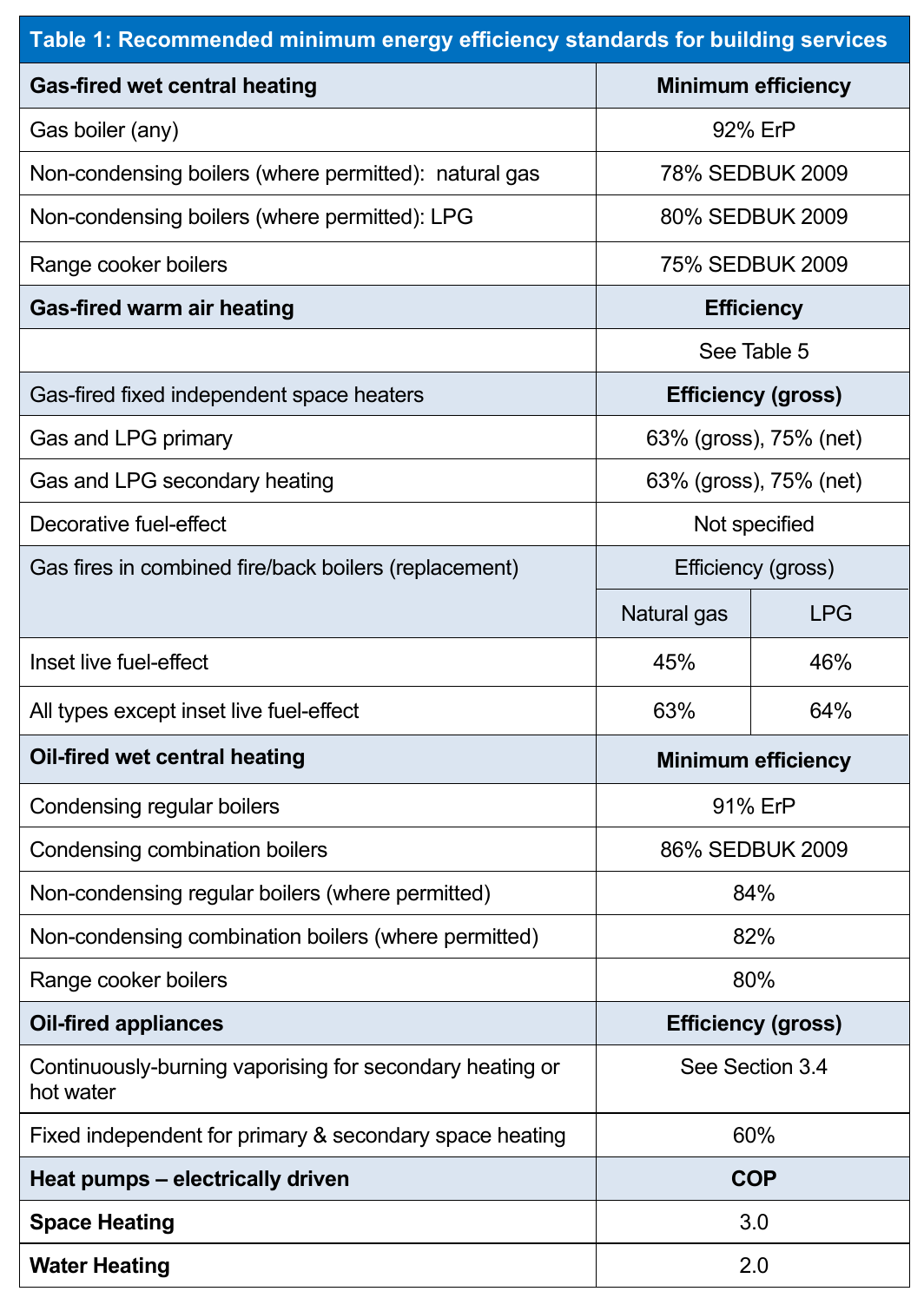
Page 14
#Source page 14
Table 1: Recommended minimum energy efficiency standards for building services
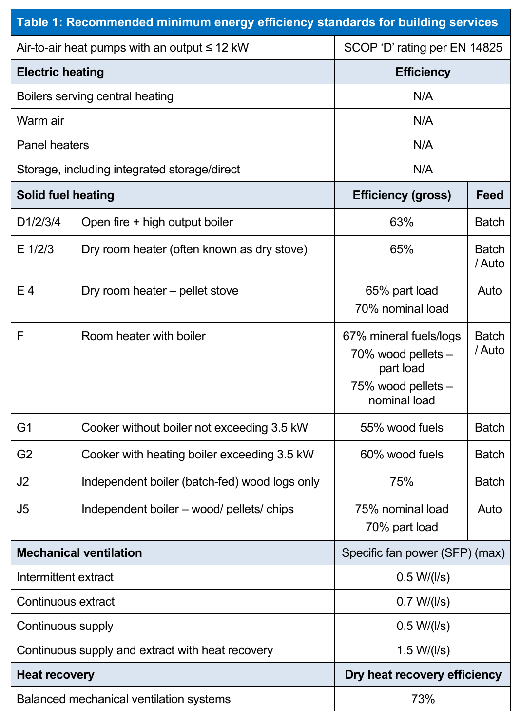
Page 15
#Source page 15
| Table 1: Recommended minimum energy efficiency standards for building services | |
| Comfort cooling | Energy efficiency ratio (SEER) |
| Air conditioners working in cooling mode | 4.0 |
| Fixed air conditioners | > Class C in Schedule 3 of the labelling scheme (The Energy Information (Household Air Conditioners) (No. 2) Regulations, SI 2005/1726) |
| Fixed lighting | Lighting efficacy |
| Internal light fittings (100%) | 75 lamp lumens per circuit-watt |
| External lighting – automatic presence and daylight control | 75 lamp lumens per circuit-watt |
Section 2: Gas-fired space and water heating
#Source page 16
2.1 Scope of guidance
This section provides guidance on the specification of gas-fired space heating and hot water systems6 in dwellings to meet relevant energy efficiency requirements in building regulations. The guidance applies to systems fuelled by natural gas and liquid petroleum gas (LPG) and covers:
•wet central heating systems
•range cookers with integral central heating boilers
•warm air heating systems
•fixed independent space heating devices.
2.2 Gas-fired wet central heating systems
New systems
New systems for gas-fired wet central heating in new and existing dwellings should meet the minimum standards for:
a.boiler efficiency, system circulation, hot water storage, system preparation and commissioning in Table 2
b.boiler interlock, zoning, and time and temperature control of the heating and hot water circuits in Table 3
c.Refer to Section 9 for further information on insulation of hot water storage vessels, and pipework.
Existing systems
Components installed as replacements in existing systems should meet the same standards as for new systems, except where indicated otherwise in Table 4.
If work includes replacement of the boiler, at least one of the energy efficiency measures in the ‘minimum standard column of table 4, section 2.0 should be installed.
Page 17
#Source page 17
| Table 2: Recommended minimum standards for efficiency, system circulation, hot water storage, system preparation and commissioning for gas-fired wet central heating systems | |
| Topic | Minimum standard |
| Efficiency | The boiler efficiency should be not less than 92% ErP. In existing dwellings, in the exceptional circumstances defined in the Building Standards Division document ‘Guide to the Condensing Boiler Installation Assessment Procedure for Dwelling’, the boiler SEDBUK 2009 efficiency should be not less than 78% if natural gas-fired, or not less than 80% if LPG- fired. The boiler efficiency for heating boilers that are combined with range cookers should be as defined in Section 2.3 - ‘Gas-fired range cookers with integral central heating boiler’. |
| System circulation | Space heating systems and domestic hot water primary circuits should have fully pumped circulation where this is compatible with the heat generator If the boiler manufacturer’s instructions advise installation of a bypass, an automatic bypass valve should be provided and the manufacturer’s instructions on minimum pipe length followed. |
| Hot water storage | Vented hot water storage cylinders should comply with the heat loss and heat exchanger requirements of BS 1566:2002 Part 1 or BS EN 12897 as appropriate. Copper hot water storage combination units should comply with BS 3198:1981. Primary storage systems should meet the insulation requirements of the Hot Water Association ‘Performance specification for thermal stores’. Unvented hot water storage system products should comply with BS EN 12897: 2006 The standing heat loss for all hot water storage vessels should not exceed the relevant value from Table 28 in Section 9 of this document. All hot water vessels should carry a label with the information listed in Section 9 of this document. For labelling requirements for other heat inputs, see relevant sections (e.g. Section 12 for solar). |
| System preparation and water treatment | Central heating systems should be thoroughly cleaned and flushed out before installing a new boiler. During final filling of the system, a chemical water treatment inhibitor meeting the manufacturer’s specification or other appropriate standard should be added to the primary circuit to control corrosion and the formation of scale and sludge. |
Page 18
#Source page 18
| Table 2: Recommended minimum standards for efficiency, system circulation, hot water storage, system preparation and commissioning for gas-fired wet central heating systems | |
| Topic | Minimum standard |
| Installers should also refer to the boiler manufacturer’s installation instructions for appropriate treatment products and special requirements for individual boiler models. Where the mains total water hardness exceeds 200 parts per million, provision should be made to treat the feed water to water heaters and the hot water circuit of combination boilers to reduce the rate of accumulation of limescale. For solar thermal systems, see Section 12. | |
| Commissio ning | On completion of the installation of a boiler or hot water storage system and associated equipment such as pipework, pumps and controls, the equipment should be commissioned in accordance with the manufacturer’s instructions and BS 7593: 2019. The manufacturer’s instructions will be specific to the particular boiler or hot water storage system. The ‘Benchmark Commissioning Checklist’ can be used to show that commissioning has been carried out satisfactorily for the heating and hot water system and its heat generation source. The installer should explain fully to the user how to operate the system in an energy efficient manner, and leave behind any user manuals provided by manufacturers. |
| Table 3: Recommended minimum standards for control of gas-fired wet central heating systems¹ | |
| Control type | New systems |
| Boiler interlock | System controls should be provided so that when there is no demand for space heating or hot water, the boiler and pump are switched off. Systems to have a sufficient flow of water to avoid short-cycling |
| Zoning | Dwellings with a total floor area > 150 m² should have at least two space heating zones, each with an independently controlled heating circuit². Dwellings with a total floor area³ < 150 m² may have a single space heating zone⁴. |
| Control of space heating | Each space heating circuit should be provided with: • independent time control and either: • a room thermostat or programmable room thermostat located in a reference room ⁵ served by the heating circuit, together with |
Page 19
#Source page 19
| Table 3: Recommended minimum standards for control of gas-fired wet central heating systems¹ | |
| Control type | New systems |
| individual radiator controls such as thermostatic radiator valves (TRVs), on all radiators outside the reference rooms⁶; or • individual networked radiator controls in each room on the circuit. | |
| Control of hot water | Domestic hot water circuits supplied from a hot water store (i.e. not produced instantaneously as by a combination boiler) should be provided with: • independent time control, and • electronic temperature control |
Notes
1.Always also follow manufacturers’ instructions.
2.A heating circuit refers to a pipework run serving a number of radiators that is controlled by its own zone valve.
3.The relevant floor area is the area within the insulated envelope of the dwelling, including internal cupboards and stairwells.
4.The SAP notional dwelling assumes at least two space heating zones for all underfloor areas, unless the dwelling is single storey, open plan, with a living area >70% of the total floor area
5.A reference room is a room that will act as the main temperature control for the whole circuit and where no other form of system temperature control is present.
6.It may be justified to control a heating zone rather than individual rooms where any of the following apply.
a.In single-storey, open-plan dwellings in which the living area is greater than 70 per cent of the total floor area, sub-zoning of temperature control might not be appropriate. In such cases, the dwelling should be considered as a single heating zone.
b.Where two adjacent rooms have a similar function and heating requirements (e.g. kitchen and utility room).
Page 20
#Source page 20
Table 4: Recommended minimum standards when replacing components of gas-fired wet central heating systems 1 2
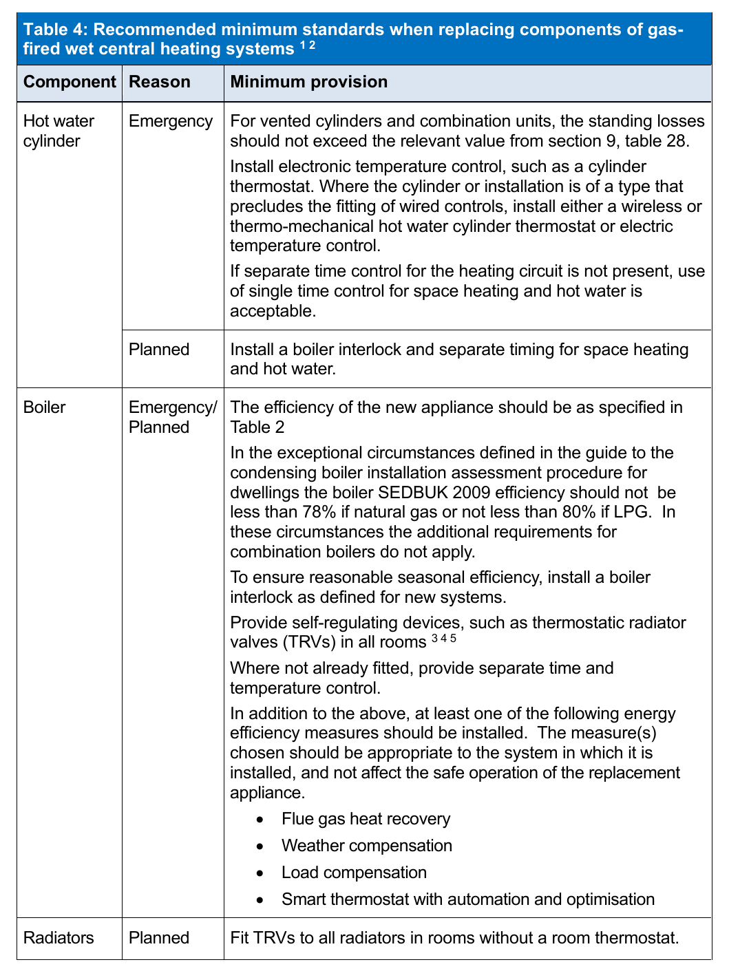
Page 21
#Source page 21
Table 4: Recommended minimum standards when replacing components of gas-fired wet central heating systems 1 2
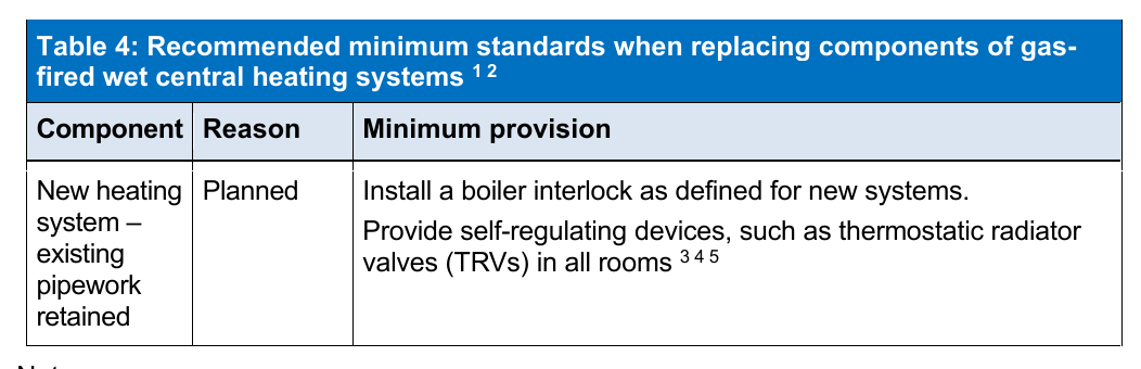
Notes:
1.Always also follow manufacturers’ instructions.
2.Best practice would be as for a new system.
3.It may be justified to control a heating zone rather than individual rooms where any of the following apply.
•In single-storey, open-plan dwellings in which the living area is greater than 70 per cent of the total floor area, sub-zoning of temperature control might not be appropriate. In such cases, the dwelling should be considered as a single heating zone.
•Where two adjacent rooms have a similar function and heating requirements (e.g. kitchen and utility room).
4.It might not be possible to equip some heating system types with self-regulating devices for the control of individual rooms. Such systems must only be used where controlling a whole heating zone can be justified.
Where it is not technically feasible to install self-regulating devices the requirement does not need to be met. This includes, but is not limited to:
•Buildings with very low heat demand (e.g. <10 W/m 2).
•Homes with buffer zones for heat absorption or dissipation with high thermal mass.
5.The requirement for self-regulating devices may be satisfied by providing any of the following.
a.An individual networked heat emitter control for each emitter.
b.Both of the following.
•A thermostat in a room that the heating circuit serves.
•An individual self-regulating device for each heat emitter, such as a thermostatic radiator valve, on all heat emitters outside the room which contains the thermostat. TRVs should not be located in the same room as the thermostat.
c.An individual room/ heating zone thermostat or fan coil thermostat for each room/heating zone.
d.Any other controls which fulfil the function of a self-regulating device.
2.3 Gas-fired range cookers with integral central heating boiler
#Source page 22
Note: This section does not apply to appliances with fully independent boiler and cooker parts within a shared case – refer instead to Section 2.2.
Where gas-fired range cookers with an integral central heating boiler (within a single appliance body), are provided as part of a new system or as a replacement component:
a.The appliance should have two independently controlled burners (one for the cooking function and one for the boiler).
b.The SEDBUK 2009 efficiency of the integral boiler should be not less than 75%. The manufacturer’s declaration of appliance performance and SEDBUK value should include the following statement and information:
•Seasonal efficiency (SEDBUK) = xx %
•Case heat emission value = yy kW
•Heat transfer to water at full load = zz kW
•The values are used in the UK Government’s Standard Assessment Procedure (SAP) for the energy rating of dwellings. The test data from which the values have been calculated has been certified by [insert name and/or identification of Notified body]. See: www.rangeefficiency.org.uk.
If the integral boiler is a condensing boiler, the declaration should make clear whether the efficiency has been calculated in accordance with SEDBUK 2005 or SEDBUK 2009. If it does not, then SEDBUK 2005 must be assumed.
c.The integral boiler should meet the minimum standards for system circulation, hot water storage, system preparation, commissioning and controls in Tables 2, 3 and 4 (gas-fired central heating systems) and for insulation (Section 9).
2.4 Gas-fired warm air heating
New systems and replacement components for gas-fired warm air heating should meet the minimum standards for:
•efficiency and installation in Table 5
•zoning, time control and temperature control for
(a) space heating without hot water and
(b) space heating combined with water heating in Table 6.
Page 23
#Source page 23
| Table 5: Recommended minimum standards for efficiency and installation of gas- fired warm air heating systems | |
| Topic | Minimum standard |
| Efficiency | Gas-fired warm air units should meet the requirements, as appropriate to the design of the appliance, of BS EN 17082:2009, If a gas-fired circulator is incorporated in the warm air unit to provide domestic hot water, it should be able to deliver full and part load efficiency at least equal to that prescribed by BS EN 15502-2. The manufacturer’s declaration of appliance performance should include the following words: Combined warm air unit and circulator This product has been assessed against the test methods set out in BS EN 17082:2019 and certified as meeting those minimum requirements by {insert name or identification of Notified Body}. BS EN 17082:2009 Warm air unit alone This product has been assessed against the test method set out in BS EN 17082:2019 and certified as meeting the minimum requirements by {insert name and/or identification of Notified Body}. *Delete as appropriate |
| Installation | The system should be installed in accordance with BS 5864:2010. Ductwork that is newly installed or replaced should be insulated in accordance with the recommendations of BS 5422:2009 (see Section 9). |
| Table 6: Recommended minimum standards for control of gas-fired warm air heating systems | |
| Without hot water | Minimum standard |
| Time and temperature control | Where controls are external to heater, the system should be provided with a time switch/ programmer and room thermostat, or programmable room thermostat. Where controls are integrated in the heater, the system should be provided with a time-switch/ programmer and room temperature sensor linked to heater firing and fan speed control. Provide self-regulating devices in all rooms to enable the separate control of heating to each room. 1 2 3 |
Page 24
#Source page 24
Table 6: Recommended minimum standards for control of gas-fired warm air heating systems
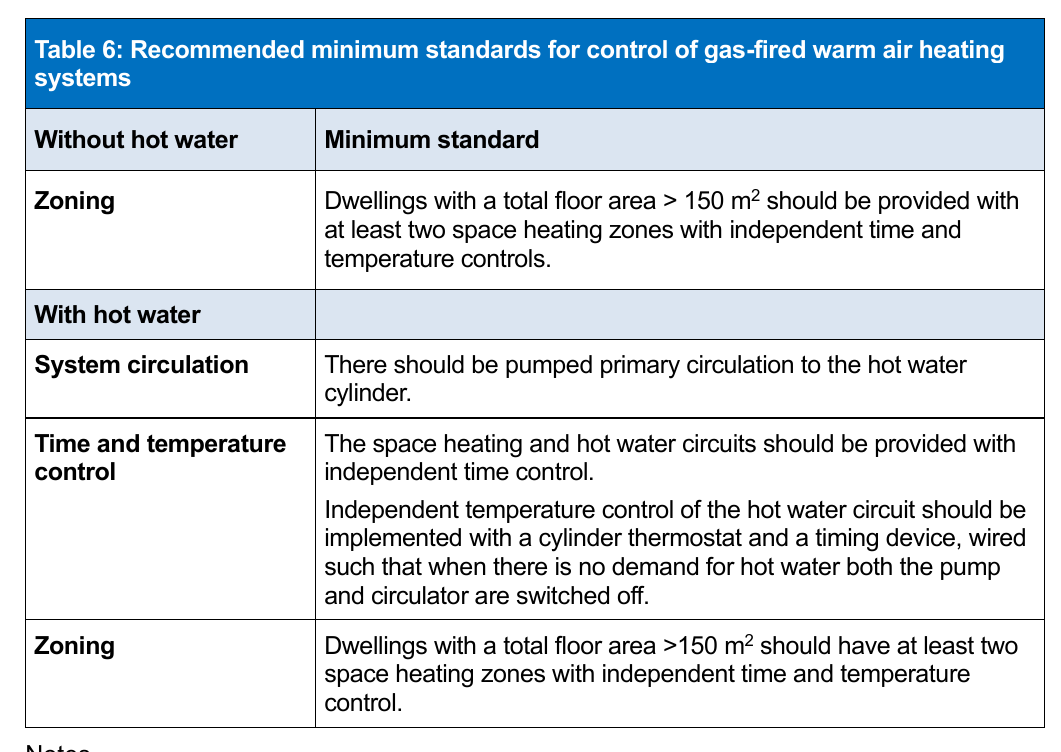
1.It may be justified to control a heating zone rather than individual rooms where any of the following apply.
a.In single-storey, open-plan dwellings in which the living area is greater than 70 per cent of the total floor area, sub-zoning of temperature control might not be appropriate. In such cases, the dwelling should be considered as a single heating zone.
b.Where two adjacent rooms have a similar function and heating requirements (e.g. kitchen and utility room).
It might not be possible to equip some heating system types with self-regulating devices for the control of individual rooms. Such systems must only be used where controlling a whole heating zone can be justified.
2.Where it is not technically feasible to install self-regulating devices the requirement does not need to be met. This includes, but is not limited to:
•Buildings with very low heat demand (e.g. <10 W/m 2).
•Homes with buffer zones for heat absorption or dissipation with high thermal mass.
3.The requirement for self-regulating devices may be satisfied by providing any of the following.
a.An individual networked heat emitter control for each emitter.
2.5 Gas-fired fixed independent space heating appliances
#Source page 25
b.Both of the following.
•A thermostat in a room that the heating circuit serves.
•An individual self-regulating device for each heat emitter, such as a thermostatic radiator valve, on all heat emitters outside the room which contains the thermostat. TRVs should not be located in the same room as the thermostat.
c.An individual room/ heating zone thermostat or fan coil thermostat for each room/heating zone.
d.Any other controls which fulfil the function of a self-regulating device.
2.5 Gas-fired fixed independent space heating appliances
Fixed independent space heating appliances may be installed as a means of primary or secondary space heating.
Gas-fired fixed independent appliances for primary space heating
Where gas-fired fixed independent space heating appliances in new and existing dwellings are provided as the primary heat source:
a.The appliance should be one of the types described in Table 7.
b.The efficiency of the appliance (gross calorific value) should be not less than 63% (70% net).
c.The appliance manufacturer’s declaration of appliance performance should include the following statement and information:
“The efficiency of this appliance has been measured as specified in [insert appropriate entry from Table 7] and the result after conversion to gross using the appropriate factor from Table E4 of SAP 10 is xx %. The test data has been certified by [insert name and/or identification of Notified Body]”.
The gross efficiency value may be used in the UK Government’s Standard Assessment Procedure (SAP) for energy rating of dwellings.
For new systems each appliance should be capable of controlling the temperatures independently in areas that have different heating needs (e.g. separate sleeping and living areas). In existing systems, temperature controls should be upgraded to the standards required for new systems.
2.6 Gas-fired fixed decorative fuel-effect fires
#Source page 26
Table 7: Appropriate types of natural gas and LPG-fired fixed independent appliances for primary space heating
British Standard designation (appliance type)
BS EN 1266:2002 – ‘Independent gas-fired convection heaters incorporating a fan to assist transportation of combustion air and/or flue gases’.
BS 7977-1:2009+A1:2013 – ‘Specification for safety and rational use of energy of domestic gas appliances. Radiant/convectors’.
BS EN 613:2001 – ‘Independent gas-fired convection heaters’.
BS EN 13278:2003 – ‘Open fronted gas-fired independent space heaters’.
Gas-fired fixed independent appliances for secondary space heating
Where gas-fired fixed independent space heating appliances are provided as the secondary heat source, the guidance for primary heating given above applies. Two further types of appliance are describe in Table 8:
| Table 8: Appropriate types of natural gas and LPG-fired fixed independent appliances for secondary space heating | |
| Any of the appliance standards listed in Table 7, plus: | |
| BS EN 14829:2007 – ‘Independent gas-fired flueless space heaters for nominal heat input not exceeding 6 kW’. | Thermal efficiency requirements for this type of appliance are not specified as all the heat produced by the combustion process is released into the space to be heated. In SAP 10, the efficiency of these appliances is classed as 90% and an adjustment is made for ventilation in the space heating requirement calculation. |
| BS EN 449:2002+A1:2007 – ‘Specification for dedicated liquefied petroleum gas appliances. Domestic flueless space heaters (including diffusive catalytic combustion heaters)’. |
2.6 Gas-fired fixed decorative fuel-effect fires
This type of appliance is intended for decorative purposes and therefore a minimum thermal efficiency is not specified.
Gas-fired decorative fires in new and existing dwellings should:
a.meet the product standards in BS EN 509: 2000 – ‘Decorative fuel-effect gas appliances’; and
b.number not more than one appliance per 100 m 2 of dwelling floor area.
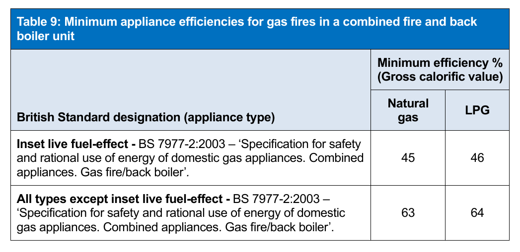
2.7 Gas fires - secondary space heating as part of combined fire and back boiler unit
Where gas fires are provided as a secondary heat source as part of a combined fire and back boiler unit in an existing system the standards in BS 7977-2 should be met and:
Page 27
#Source page 27
a.The efficiency (gross calorific value) of the appliance should be not less than the value in Table 9 for that type of appliance.
b.The appliance manufacturer’s declaration of appliance performance should include the following statement and information
“The efficiency of this appliance has been measured as specified in [insert appropriate entry from Table 9] and the result after conversion to gross using the appropriate factor from Table E4 of SAP 10 is xx%. The test data from which it has been calculated has been certified by [insert name and/or identification of Notified Body].“
The efficiency value may be used in the UK Government’s Standard Assessment Procedure (SAP) for energy rating of dwellings.
Table 9: Minimum appliance efficiencies for gas fires in a combined fire and back boiler unit
Section 3: Oil-fired space and water heating
#Source page 28
3.1 Scope of guidance
This section provides guidance on the specification of oil-fired space heating and hot water systems7 in dwellings to meet relevant energy efficiency requirements in the building regulations. The guidance applies to the following types of oil-fired heating system:
•wet central heating systems
•range cookers with integral central heating boilers
•vaporising appliances providing secondary heating or hot water
•fixed independent space heating devices.
3.2 Oil-fired wet central heating systems
New systems
New systems for oil-fired central heating in new and existing dwellings should meet the minimum standards for:
a.boiler efficiency, system circulation, hot water storage, system preparation and commissioning in Table 10.
b.boiler interlock, zoning, and time and temperature control of the heating and hot water circuits in Table 11
c.vessel and pipework insulation in Section 9.
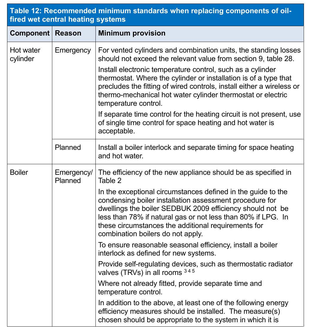
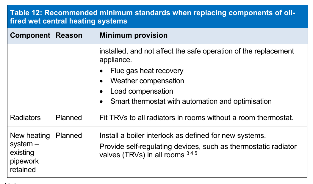
Work on existing systems
Components installed as replacements in existing systems should meet the same standards as for new systems, except where indicated otherwise in Table 12.
| Table 10: Recommended minimum standards for efficiency, system circulation, hot water storage, system preparation and commissioning for oil-fired wet central heating systems | |
| Topic | Minimum standard |
| Efficiency | Regular boilers The boiler should be of the condensing type. The boiler efficiency should be not less than 91% ErP. |
Page 29
#Source page 29
| Table 10: Recommended minimum standards for efficiency, system circulation, hot water storage, system preparation and commissioning for oil-fired wet central heating systems | |
| Topic | Minimum standard |
| Combination boilers The boiler should be of the condensing type. The boiler SEDBUK 2009 efficiency should be not less than 86%. In existing dwellings, in the exceptional circumstances defined in the Building Standards Division document ‘Guide to the Condensing Boiler Installation Assessment Procedure for Dwelling’, the boiler SEDBUK 2009 efficiency should be not less than 82%. Range cooker boilers The boiler efficiency for heating boilers that are combined with range cookers should be as defined in Section 3.3 - Oil-fired cookers with integral central heating boilers. | |
| System circulation | Space heating systems and domestic hot water primary circuits should have fully pumped circulation where this is compatible with the heat generator. If the boiler manufacturer’s instructions advise installation of a bypass, an automatic bypass valve should be provided and the manufacturer’s instructions on minimum pipe length followed. |
| Hot water storage | Vented hot water storage cylinders should comply with the heat loss and heat exchanger requirements of BS 1566:2002 Part 1 or BS EN 12897 as appropriate. Copper hot water storage combination units should comply with BS 3198:1981. Primary storage systems should meet the insulation requirements of the Hot Water Association ‘Performance specification for thermal stores’. Unvented hot water storage system products should comply with BS EN 12897: 2006. The standing heat loss for all hot water storage vessels should not exceed the relevant value from table 28 in Section 9. All hot water vessels should carry a label with the information listed in Section 9 of this document. For labelling requirements for other heat inputs, see relevant sections (e.g. Section 12 for solar). |
| System preparation and water treatment | Central heating systems should be thoroughly cleaned and flushed out before installing a new boiler. During final filling of the system, a chemical water treatment inhibitor meeting the manufacturer’s specification or other appropriate standard should be |
Page 30
#Source page 30
| Table 10: Recommended minimum standards for efficiency, system circulation, hot water storage, system preparation and commissioning for oil-fired wet central heating systems | |
| Topic | Minimum standard |
| added to the primary circuit to control corrosion and the formation of scale and sludge. Installers should also refer to the boiler manufacturer’s installation instructions for appropriate treatment products and special requirements for individual boiler models. Where the mains total water hardness exceeds 200 parts per million, provision should be made to treat the feed water to water heaters and the hot water circuit of combination boilers to reduce the rate of accumulation of limescale. For solar thermal systems, see Section 12. | |
| Commissio ning | On completion of the installation of a boiler or a hot water storage system, together with associated equipment such as pipework, pumps and controls, the equipment should be commissioned in accordance with the manufacturer’s instructions and BS 7593: 2019. The manufacturer’s instructions will be specific to the particular boiler or hot water storage system. The installer should explain fully to the user how to operate the system in an energy efficient manner, and behind any user manuals provided by manufacturers. |
Additional recommendations:
System preparation and water treatment - Inhibitors should be BuildCert approved or equivalent.
Limescale can be controlled by the use of chemical limescale inhibitors, combined corrosion and limescale inhibitors, polyphosphate dosing, electrolytic scale reducers or water softeners. The relevant standard for water treatment is BS 7593:2019 – ‘Code of practice for the preparation, commissioning and maintenance of domestic central heating and cooling water systems’. Manufacturers should be consulted for advice, paying particular attention to dosage levels.
Special radiator valves are available that will seal off the radiator as well as the heating circuit to prevent loss of inhibitor when removing a radiator for service or maintenance.
A filter can also be fitted to the central heating circuit to help maintain the efficiency and reliability of the system.
Commissioning - The Oil Controlled Document System (as produced and managed by OFTEC) can be used to show that oil-fired appliances and related systems have been installed and commissioned satisfactorily by listing and recording works and checks which are deemed necessary for the efficient operation of the appliance and system in compliance with the building regulations. A copy of each completed form is left with the householder or agent for record and/or Building Standards inspection purposes, and a copy is retained by the issuing installer and engineer.
OFTEC branded forms are provided for the use of OFTEC Registered installers and non-OFTEC branded forms are available for others carrying out oil-fired installation and commissioning works. To assist installers OFTEC oil appliance manufacturing members may provide forms CD/10 & CD/11 or equivalent ‘Boiler Passport’ with their equipment.
Page 31
#Source page 31
Controlled Document CD/10 - Installing engineers should complete OFTEC Form CD/10 to show that they have compliantly completed the installation of an oil-fired appliance and controls, and wet system commissioning prior to final appliance commissioning.
Controlled Document CD/11 - Commissioning engineers of oil-fired appliances should complete OFTEC Form CD/11 to record and show that they have completed the commissioning of the appliance and that they have left it operating in a safe and efficient manner.
| Table 11: Recommended minimum controls of oil-fired wet central heating systems | |
| Control Type | Minimum standard |
| Boiler interlock | System controls should be wired so that when there is no demand for space heating or hot water, the boiler and pump are switched off. Systems to have a sufficient flow of water to avoid short-cycling. |
| Zoning | Dwellings with a total floor area > 150 m² should have at least two space heating zones, each with an independently controlled heating circuit². Dwellings with a total floor area³ ≤ 150 m² may have a single space heating zone⁴. |
| Control of space heating | Each space heating circuit should be provided with: independent time control, and either: • a room thermostat or programmable room thermostat located in a reference room⁵ served by the heating circuit, together with individual radiator controls such as thermostatic radiator valves (TRVs), on all radiators outside the reference rooms ⁶ or • individual networked radiator controls in each room on the circuit. |
| Control of hot water | Domestic hot water circuits supplied from a hot water store (i.e. not produced instantaneously as by a combination boiler) should be provided with: • independent time control, and • electronic temperature control. |
Notes:
1.Always also follow manufacturers’ instructions.
2.A heating circuit refers to a pipework run serving a number of radiators that is controlled by its own zone valve.
3.The relevant floor area is the area within the insulated envelope of the dwelling, including internal cupboards and stairwells.
4.The SAP notional dwelling assumes at least two space heating zones for all floor areas unless the dwelling is single storey, open plan with a living >70% of the total floor area.
5.A reference room is a room that will act as the main temperature control for the whole circuit and where no other form of system temperature control is present.
Page 32
#Source page 32
6.It may be justified to control a heating zone rather than individual rooms where any of the following apply.
a.In single-storey, open-plan dwellings in which the living area is greater than 70 per cent of the total floor area, sub-zoning of temperature control might not be appropriate. In such cases, the dwelling should be considered as a single heating zone.
b.Where two adjacent rooms have a similar function and heating requirements (e.g. kitchen and utility room).
Table 12: Recommended minimum standards when replacing components of oil-fired wet central heating systems
Page 33
#Source page 33
Table 12: Recommended minimum standards when replacing components of oil-fired wet central heating systems
Notes:
1.Always also follow manufacturers’ instructions.
2.Best practice would be as for a new system.
3.It may be justified to control a heating zone rather than individual rooms where any of the following apply.
•In single-storey, open-plan dwellings in which the living area is greater than 70 per cent of the total floor area, sub-zoning of temperature control might not be appropriate. In such cases, the dwelling should be considered as a single heating zone.
•Where two adjacent rooms have a similar function and heating requirements (e.g. kitchen and utility room).
4.It might not be possible to equip some heating system types with self-regulating devices for the control of individual rooms. Such systems must only be used where controlling a whole heating zone can be justified.
Where it is not technically feasible to install self-regulating devices the requirement does not need to be met. This includes, but is not limited to:
•Buildings with very low heat demand (e.g. <10 W/m 2).
•Homes with buffer zones for heat absorption or dissipation with high thermal mass.
5.The requirement for self-regulating devices may be satisfied by providing any of the following.
a.An individual networked heat emitter control for each emitter.
3.3 Oil-fired range cookers with integral central heating boilers
#Source page 34
b.Both of the following.
•A thermostat in a room that the heating circuit serves.
•An individual self-regulating device for each heat emitter, such as a thermostatic radiator valve, on all heat emitters outside the room which contains the thermostat. TRVs should not be located in the same room as the thermostat.
c.An individual room/ heating zone thermostat or fan coil thermostat for each room/heating zone.
d.Any other controls which fulfil the function of a self-regulating device.
3.3 Oil-fired range cookers with integral central heating boilers
This section provides guidance on the specification of oil-fired range cookers with integral central heating boilers for space heating and hot water in dwellings.
Note: The guidance applies only to twin-burner cooker boilers, which should not be confused with the type of range cooker described as a single burner ‘dry heat’ range cooker. The latter is intended only to provide a cooking function, is not included in SAP 10 calculations, and does not come within the scope of the building regulations energy efficiency requirements.
Where oil-fired range cookers with an integral central heating boiler are provided as part of new systems or as replacement components in existing systems:
a.The appliance should have two independently controlled burners (one for the cooking function and one for the boiler).
b.The SEDBUK 2009 efficiency of the integral boiler should be not less than 80%.
c.The manufacturer’s declaration of appliance performance and SEDBUK value should include the following statement and information
•Seasonal efficiency (SEDBUK) = xx%
•Case heat emission value = yy kW
•Heat transfer to water at full load = zz kW
•The efficiency values may be used in the UK Government’s Standard Assessment Procedure (SAP) for the energy rating of dwellings. The test data from which they have been calculated has been certified by [insert name and/or identification of Notified body]. See www.rangeefficiency.org.uk.
If the integral boiler is a condensing boiler, the declaration should make clear whether the efficiency has been calculated in accordance with SEDBUK 2005 or SEDBUK 2009. If it does not, then SEDBUK 2005 must be assumed.
d.The integral boiler should meet the minimum standards for system circulation, hot water storage, system preparation, commissioning and controls in Tables 10, 11 and 12 (oil-fired central heating systems) and for insulation (Section 9).
3.4 Continuously burning oil-fired vaporising appliances for secondary heating or hot water
#Source page 35
This section provides guidance on the specification of oil-fired vaporising appliances providing secondary heating or hot water for dwellings. The guidance does not apply to appliances which have been converted from another fuel (for example from solid fuel to oil).
Oil-fired vaporising appliances provided with new systems or as replacement components in existing systems should meet the minimum standards for controls in Table 13.
| Table 13: Recommended minimum standards for control of continuously burning oil-fired vaporising appliances | |
| Appliance type | Minimum standard |
| Manually operated appliance, e.g. room heater. | Integral manual controls as provided by appliance manufacturer. |
| Electrically operated appliance, e.g. room heater. | Integral remote or thermostatic control should be provided as provided (or specified) by the appliance manufacturer. |
| Automatic ON/OFF vaporising appliances | |
| Room heater providing (secondary) space heating. | Integral thermostatic controls as provided by the appliance manufacturer. |
| Room heater providing domestic hot water & (secondary) space heating. | Integral or remote thermostatic controls as provided (or specified) by the appliance manufacturer. |
3.5 Oil-fired fixed independent space heating appliances
This section provides guidance on the specification of oil-fired fixed independent appliances for primary or secondary space heating in dwellings.
Oil-fired fixed independent appliances for primary heating
Where oil-fired fixed independent space heating appliances are provided as the primary heat source in new dwellings:
a.The efficiency of the appliance (gross calorific value) should be not less than 60%. Gross efficiencies calcualteds in accordance with the product standard relevant to the appliance is converted using Table E4 of SAP 10 to give a new efficiency.
b.As noted in SAP Appendix E2, the appliance manufacturer’s declaration of appliance performance should include the following words:
"The net efficiency of this appliance has been measured as specified in [insert appropriate entry from Table E1, Table E2 or Table E3] and the result after conversion to gross using the appropriate factor from Table E4 of SAP 2009 is [x]%. The test data have been certified by [insert name and/or identification of Notified Body]. The gross efficiency value may be used in the UK
Page 36
#Source page 36
Government’s Standard Assessment Procedure (SAP) for energy rating of dwellings."
c.Each appliance should be capable of controlling the temperatures independently in areas that have different heating needs (e.g. separate sleeping and living areas).
Oil-fired fixed independent appliances for secondary heating
Oil-fired fixed independent space heating appliances in new dwellings which are provided as the secondary heat source should have an efficiency (gross calorific value) of not less than 60%.
Section 4: Heat pumps
#Source page 37
4.1 Scope of guidance
This section provides guidance on the specification of heat pump systems in dwellings for the provision of space heating and domestic hot water to meet relevant energy efficiency requirements in the building regulations.
A heat pump is a device which takes heat energy from a low temperature source and upgrades it to a higher temperature at which it can be usefully employed for heating or hot water. Heat pumps may supply all or part of the heating load.
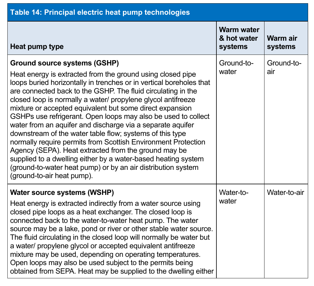
The guidance in this section applies to the types of electrically-driven heat pump in Table 14 used as the heat generator in underfloor, warm air and medium temperature radiator heating systems, etc.
Table 14: Principal electric heat pump technologies
4.2 Key terms
#Source page 38
Table 14: Principal electric heat pump technologies
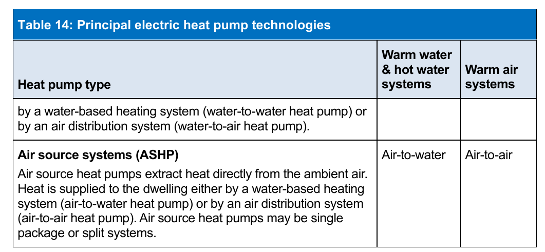
Supplementary information - All heat pump systems are at their most efficient when the source temperature is as high as possible, the heat distribution temperature is as low as possible and pressure losses in air and water systems are kept to a minimum. If installed in a new dwelling, heat pumps should use refrigerants complying with the provisions of current F-gas Regulations. Heat pumps should be CE marked in accordance with applicable EU Directives: e.g. the machinery safety, low voltage, pressure equipment and electromagnetic compatibility Directives. If summer cooling is provided by the heat pump, it is recommended that condensate drainage from the indoor units is provided.
4.2 Key terms
Coefficient of performance (COP) is a measure of the efficiency of a heat pump at specified source and sink temperatures, measured using the procedures in BS EN 14511-2:
Heating COP = heat output / power input Equation 4
% COP (COP x 100) is the heat generator efficiency.
Seasonal coefficient of performance (SCOP) is the overall coefficient of performance of the unit for the designated heating season. It makes general assumptions about the amount of auxiliary heating needed to top up the space and water heating available from the heat pump.
SCOP is measured in accordance with the procedures in BS EN 14825:2013 – ‘Air conditioners, liquid chilling packages and heat pumps with electrically driven compressors for space heating and cooling. Testing and rating at part load conditions and calculation of seasonal performance’.
The National Calculation Methodology for calculating carbon dioxide emission rates from buildings uses SCOP.
4.3 Warm water and hot water heat pumps
Heat pumps in new and existing buildings should:
Page 39
#Source page 39
a.have a COP which is not less than 3.0 for space heating and not less than 2.0 for domestic hot water; or
b.if air-to-air heat pumps with an output less than or equal to 12 kW, follow the Ecodesign Commission Regulation No. 2016/2281 for air heating products, cooling products, high temperature process chillers and fan coil units; and
c.feature as a minimum the controls package in Table 15 or Table 16.
| Table 15: Recommended minimum standards for warm water and hot water heat pumps (ground-to-water, water-to-water and air-to-water systems) | |
| Topic | Minimum standard |
| Supply water temperature | Underfloor heating - Supply water temperatures to the underfloor heating system should be in the range 30 °C to 40 °C for new buildings and 30 °C to 55 °C for existing systems. Radiators - High-efficiency radiators with high water volume should be utilised. Supply water temperature to the radiators should be in the range 40 °C to 55 °C. Fan coil units - Supply water temperature to the fan coil units should be in the range 35 °C to 45 °C. |
| Installation | The water distribution system should be arranged for reverse return operation or arranged with a low loss manifold system to maximise efficiency and ease commissioning and future maintenance. Pipework not contributing to the space heating should be insulated to prevent heat loss, following the table below. If summer cooling is provided by the heat pump, all water distribution pipework should be insulated to prevent condensation, following the guidance in the table below. External pipework between the dwelling and the ground heat exchanger should be insulated, following the guidance in the table below. The ground loop water circuit should be protected with an anti-freeze solution and inhibitor as recommended by the heat pump manufacturer. Ground loops should be cleaned with a cleaning fluid and biocide as part of the commissioning process. The internal water distribution circuit should contain an inhibitor and may be protected by an anti-freeze solution as recommended by the heat pump manufacturer. Ground loops should be filled with a heat transfer fluid. Installers should also refer to the equipment manufacturer’s installation instructions for appropriate treatment products and special requirements for individual appliance models. |
Page 40
#Source page 40
| Table 15: Recommended minimum standards for warm water and hot water heat pumps (ground-to-water, water-to-water and air-to-water systems) | |
| Topic | Minimum standard |
| Zoning | Dwellings with a total floor area > 150 m² should have at least two space heating zones, each with an independently controlled heating circuit¹. Dwellings with a total floor area ² < 150 m ² may have a single space heating zone ³ |
| System Controls | Heat pump unit controls should include: • control of water pump operation (internal and external as appropriate) • control of water temperature for the distribution system • defrost control of external airside heat exchanger for air-to-water systems • protection for water flow failure • protection for high water temperature • protection for high refrigerant pressure • protection for air flow failure on air-to-water units. External heat pump controls should include: • weather compensation or internal temperature control • timer or programmer for space heating. System controls should be wired to maximise the efficiency of the heating and hot water system and to extend the life of the heating appliance. When there is no demand for space heating or hot water and the associated buffer vessel is maintained at the correct design temperature, the heating appliance and pump are switched off |
| Control of space heating | Each space heating circuit should be provided with independent time control and either: • a room thermostat or programmable room thermostat located in a reference room⁴ served by the heating circuit, together with individual emitter controls such as thermostatic radiator valves (TRVs), on all emitters outside the reference rooms⁵; or • individual networked enitter controls in each room on the circuit. |
| Control of hot water | The domestic hot water system should have temperature control (e.g. a tank thermostat) and time control to optimise the time taken to heat the water. |
Page 41
#Source page 41
| Table 15: Recommended minimum standards for warm water and hot water heat pumps (ground-to-water, water-to-water and air-to-water systems) | |
| Topic | Minimum standard |
| Commissioning | Manufacturers’ instructions for commissioning and BS 7593: 2019 should be followed and a commissioning record should be completed to show compliance. Where relevant, the ‘Benchmark Commissioning Checklist’ can be used to show that commissioning has been carried out satisfactorily for the heating and hot water system and its heat generation source. The installer should explain fully to the user how to operate the system in an energy efficient manner, and behind any user manuals provided by manufacturers. |
Notes:
1.A heating circuit refers to a pipework run serving a number of radiators that is controlled by its own zone valve.
2.The relevant floor area is the area within the insulated envelope of the dwelling, including internal cupboards and stairwells.
3.The SAP notional dwelling assumes at least two space heating zones for all underfloor areas, unless the dwelling is single storey, open plan, with a living area >70% of the total floor area
4.A reference room is a room that will act as the main temperature control for the whole circuit and where no other form of system temperature control is present.
5.It may be justified to control a heating zone rather than individual rooms where any of the following apply.
a.In single-storey, open-plan dwellings in which the living area is greater than 70 per cent of the total floor area, sub-zoning of temperature control might not be appropriate. In such cases, the dwelling should be considered as a single heating zone.
b.Where two adjacent rooms have a similar function and heating requirements (e.g. kitchen and utility room).
Note: It is recommended that heat pumps should be designed and installed in accordance with the technical standards given in the Microgeneration Certification Scheme’s Microgeneration Installation Standard: MIS 3005, subject to the limitations on scope as outlined in this Standard.
Notes: Inhibitors should be BuildCert approved or equivalent.
Limescale can be controlled by the use of chemical limescale inhibitors, combined corrosion and limescale inhibitors, polyphosphate dosing, electrolytic scale reducers or water softeners. The relevant standard for water treatment is BS 7593:2019 – ‘Code of practice for the preparation, commissioning and maintenance of domestic central heating and cooling water systems’. Manufacturers should be consulted for advice, paying particular attention to dosage levels.
Page 42
#Source page 42
Special radiator valves are available that will seal off the radiator as well as the heating circuit to prevent loss of inhibitor when removing a radiator for service or maintenance.
A filter can also be fitted to the central heating circuit to help maintain the efficiency and reliability of the system.”
| Table 16: Recommended minimum standards for warm air heat pumps (ground-to- air, water-to-air and air-to-air systems) | |
| Minimum standard | |
| Installation and commissioning | Minimum clearances adjacent to all airflow paths, as recommended by the manufacturer, should be maintained. Pipe sizes should be in accordance with the manufacturer’s recommendations. The refrigerant pipework on split systems should be insulated in line with the manufacturer’s recommendations. If summer cooling is provided by the heat pump, provision should be made for condensate drainage from the indoor terminal units. For ground-to-air and water-to-air systems all external pipework between the dwelling and the external heat exchanger should be insulated following Table 29 in Section 9. For ground-to-air and water-to-air systems constant water flow should be maintained through the heat pump. Manufacturers’ instructions for commissioning should be followed and a commissioning record should be completed to show compliance. The installer should explain fully to the user how to operate the system in an energy efficient manner, and behind any user manuals provided by manufacturers. |
| Zoning | Dwellings with a total floor area > 150 m² should have at least two space heating zones, each with an independently controlled heating circuit¹. Dwellings with a total floor area² < 150 m² may have a single space heating zone³ |
4.4 Supplementary Guidance
#Source page 43
| Table 16: Recommended minimum standards for warm air heat pumps (ground-to- air, water-to-air and air-to-air systems) | |
| Minimum standard | |
| Controls | Heat pump unit controls should include: • control of room air temperature (if not provided externally) • control of outdoor fan operation for air-to-air units • defrost control of external airside heat exchanger for air-to-air systems • control for secondary heating (if fitted) on air-to-air systems • control of external water pump operation for ground-to-air and water-to-air systems • protection for high refrigerant pressure • protection for indoor air flow failure • protection for external air flow failure on air-to-air units • protection for water flow failure on ground-to-air and water-to-air systems. External controls should include: • weather compensation or internal temperature control • timer or programmer for space heating |
Note: It is recommended that heat pumps should be designed and installed in accordance with the technical standards given in the Microgeneration Certification Scheme’s Microgeneration Installation Standard: MIS 3005, subject to the limitations on scope as outlined in this Standard.
4.4 Supplementary Guidance
Supplementary information
Guidance
Microgeneration Certification Scheme standard MIS 3005 – ‘Requirements for contractors undertaking the supply, design, installation, set to work, commissioning and handover of microgeneration heat pump systems’.
Microgeneration Certification Scheme standard MIS 3007 – ‘Product certification scheme requirements – heat pumps’.
‘Heat emitters guide for domestic heat pumps’, available from http://www.microgenerationcertification.org/mcs-standards/installer-standards
CE 82 – ‘Energy Efficiency Best Practice in Housing: Domestic ground source heat pumps: design and installation of closed-loop systems’.
Heat Pump Association data sheet – ‘Air-to-water heat pumps’.
Page 44
#Source page 44
HVCA TR30 – ‘Guide to good practice: Heat pumps’.
British and European Standards
BS EN 15450:2007 – ‘Heating systems in buildings. Design of heat pump heating systems’.
BS EN 15316-4-2:2008 – ‘Heating systems in buildings. Method for calculation of system energy requirements and system efficiencies. Space heating generation systems, heat pump systems’.
BS EN 378-1 2008 +(A1)(A2):2012 – ‘Refrigerating systems and heat pumps. Safety and environmental requirements and system efficiencies - Basic requirements, definitions, classifications and selection criteria’
BS EN 378-2 2008 +(A1)(A2):2012 – ‘Refrigerating systems and heat pumps. Safety and environmental requirements and system efficiencies - Design, construction, testing, marking and documentation’.
BS EN 378-3 2008 +(A1)(A2):2012 – ‘Refrigerating systems and heat pumps. Safety and environmental requirements and system efficiencies - Installation site and personal protection’.
BS EN 378-4 2008 +(A1)(A2):2012 – ‘Refrigerating systems and heat pumps. Safety and environmental requirements and system efficiencies - Operation, maintenance, repair and recovery’
ISO 13256-1: 1998 – ‘Water-source heat pumps. Testing and rating for performance - Water-to-air and brine-to-air heat pumps’.
ISO 13256-1: 1998 – ‘Water-source heat pumps. Testing and rating for performance - Water-to-water and brine-to-water heat pumps’.
Section 5: Electric heating
#Source page 45
5.1 Scope of guidance
This section provides guidance on the specification of fixed electric heating systems for dwellings to meet relevant energy efficiency requirements in the building regulations. The guidance given in this section covers the following types of fixed electric heating systems:
•electric boilers serving central heating systems
•electric warm air systems
•electric panel heaters
•electric storage systems including integrated storage/direct systems.
Portable, plug-in appliances are not covered by the building regulations or by this guide.
5.2 Electric boilers serving central heating systems
Electric boilers serving wet central heating provided with new systems or as replacement components in existing systems should meet the minimum standards for:
a.system circulation, system preparation and commissioning in Table 17a/b.
b.boiler interlock, zoning, and time control and temperature control of heating and hot water circuits in Table 18
c.hot water storage systems in Table 18
d.vessel and pipework insulation as set out in Section 9.
| Table 17a: Recommended minimum standards for system circulation, preparation and commissioning for electric wet central heating systems | |
| Topic | Minimum standard |
| System circulation | Systems for space heating and domestic hot water primary circuits in new dwellings should have fully pumped circulation. |
| System preparation and water treatment | Central heating systems should be thoroughly cleaned and flushed before installing a new boiler. During final filling of the system a chemical water treatment formulation should be added to the primary circuit to control corrosion and the formation of scale and sludge. Installers should also refer to the boiler manufacturer’s installation instructions for appropriate treatment products and special requirements for individual boiler models. Where the mains total water hardness exceeds 200 parts per million, treat the feed water to water heaters and the hot water circuit of combination boilers to reduce the rate of accumulation of limescale. |
Page 46
#Source page 46
| Table 17a: Recommended minimum standards for system circulation, preparation and commissioning for electric wet central heating systems | |
| Topic | Minimum standard |
| Commission- ing | Manufacturers’ instructions for commissioning and BS 7593: 2019 should be followed and a commissioning record should be completed to show compliance. Where relevant, the ‘Benchmark Commissioning Checklist’ can be used to show that commissioning has been carried out satisfactorily for the heating and hot water system and its heat generation source. The installer should explain fully to the user how to operate the system in an energy efficient manner, and behind any user manuals provided by manufacturers. |
Notes: Inhibitors should be BuildCert approved or equivalent.
Limescale can be controlled by the use of chemical limescale inhibitors, combined corrosion and limescale inhibitors, polyphosphate dosing, electrolytic scale reducers or water softeners. The relevant standard for water treatment is BS 7593:2019 – ‘Code of practice for the preparation, commissioning and maintenance of domestic central heating and cooling water systems’. Manufacturers should be consulted for advice, paying particular attention to dosage levels.
Special radiator valves are available that will seal off the radiator as well as the heating circuit to prevent loss of inhibitor when removing a radiator for service or maintenance.
A filter can also be fitted to the central heating circuit to help maintain the efficiency and reliability of the system.
| Table 17b: Recommended minimum standards for control of electric wet central heating systems ¹ | |
| Control Type | Minimum standard |
| Boiler temperature control | The boiler should be fitted with a flow temperature control and be capable of modulating the power input to the primary water depending on space heating conditions. |
| Boiler interlock | If the boiler supplies domestic hot water, system controls should be provided so that when there is no demand for space heating or hot water, the boiler and pump are switched off. |
| Zoning | Dwellings with a total floor area > 150 m² should have at least two space heating zones, each with an independently controlled heating circuit². Dwellings with a total floor area³ ≤ 150 m² may have a single space heating zone⁴. |
| Control of space heating | Each space heating circuit should be provided with independent time control and either: |
Page 47
#Source page 47
| • a room thermostat or programmable room thermostat located in a reference room⁵ served by the heating circuit, together with individual radiator controls such as thermostatic radiator valves (TRVs) on all radiators outside the reference rooms⁶; or • individual networked radiator controls in each room on the circuit. | |
| Control of hot water | Domestic hot water circuits supplied from a boiler and hot water store should be provided with: • independent time control, and • electric temperature control. |
Notes:
1.Always also follow manufacturers’ instructions.
2.A heating circuit refers to a pipework run serving a number of radiators that is controlled by its own zone valve.
3.The relevant floor area is the area within the insulated envelope of the dwelling, including internal cupboards and stairwells.
4.The SAP notional dwelling assumes at least two space heating zones for all floor areas unless the dwelling is single storey, open plan with a living >70% of the total floor area.
5.A reference room is a room that will act as the main temperature control for the whole circuit and where no other form of system temperature control is present.
6.It may be justified to control a heating zone rather than individual rooms where any of the following apply.
•In single-storey, open-plan dwellings in which the living area is greater than 70 per cent of the total floor area, sub-zoning of temperature control might not be appropriate. In such cases, the dwelling should be considered as a single heating zone.
•Where two adjacent rooms have a similar function and heating requirements (e.g. kitchen and utility room).
Supplementary information - More details on control systems can be found in manufacturers’ literature and on The Association of Controls Manufacturers (TACMA) website at www.heatingcontrols.org.uk.Controls may be provided by any boiler management control system that meets the specified zoning, timing and temperature and boiler interlock control requirements.
Page 48
#Source page 48
| Table 18: Recommended minimum standards for hot water storage in electric wet central heating systems | |
| Minimum standard | |
| Vented systems, including cylinders heated primarily by electricity | Copper hot water storage combination units should comply with BS 3198. Vented cylinders should comply with the heat loss and heat exchanger requirements of BS 1566-1:2002 or BS EN 12897 as appropriate. The standing heat loss for all hot water storage vessels should not exceed the relevant value from Table 28 in Section 9. For vented replacements, electrically heated combination units should be insulated such that the standing heat loss does not exceed the relevant value from the table below. This applies to electrically heated combination units as well as other electrically heated cylinders. In vented new systems, electrically heated combination units should be insulated such that the standing heat loss does not exceed the relevant value from the table below. This applies to electrically heated combination units as well as other electrically heated cylinders. |
| Unvented systems, including cylinders heated primarily by electricity | Products should comply with BS EN 12897. Cylinders heated primarily by electricity should be insulated such that their standing heat loss (Q) does not exceed the following value. Q=1.15x(0.2+0.051V2/3) kWh/day, where V is the nominal cylinder volume in litres. This applies to electrically heated combination units as well as other electrically heated cylinders. |
| Vented and unvented systems, including cylinders heated primarily by electricity | Cylinders should either be factory fitted with, or have provision for, two thermostatically controlled electrical heating elements or immersion heaters. • The lower element should be capable of heating up at least 85% of the cylinder contents. • The upper element should be capable of heating at least 60 litres of water. • The lower element should be connected to utilise the ‘off peak’ electricity tariff and the upper for boost operation. The vessel should be designed such that following reheating to 60 °C from the off peak element, at least 80% of the contents can be drawn off at 45 °C or above at a flow rate of 0.25 l/s. |
| Primary stores | Primary storage systems should meet the insulation requirements of the Hot Water Association ‘Performance specification for thermal stores’. Unvented hot water storage products should comply BS EN 12897. |
5.3 Electric heating systems (other than electric boilers for central heating)
#Source page 49
| Table 18: Recommended minimum standards for hot water storage in electric wet central heating systems | |
| Minimum standard | |
| Labelling | All hot water storage vessels should carry a label with the following information: • type of vessel • nominal capacity in litres • standing heat loss in kWh/day • heat exchanger performance in kW. Vented copper hot water cylinders should carry clear labelling on the product such as a BSI Kitemark, registered firm status or reference to an equivalent quality control scheme. Vented cylinders which are not of copper construction should be labelled as complying with the heat loss and heat exchanger requirements of BS 1566. For labelling of hot water storage vessels in solar thermal systems, see Section 12 - Solar water heating. |
5.3 Electric heating systems (other than electric boilers for central heating)
This section provides guidance on the following types of fixed electric heating systems:
•electric warm air systems
•electric panel heaters
•electric storage systems including integrated storage/direct systems.
Portable, plug-in appliances are not covered by this guide.
Fixed electric heating systems (other than with electric boilers) should meet the minimum standards for time and temperature control in Table 19.
Table 19: Recommended minimum standards for control of primary and secondary electric heating systems (other than with electric boilers)
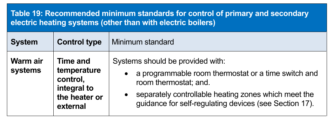
Page 50
#Source page 50
Table 19: Recommended minimum standards for control of primary and secondary electric heating systems (other than with electric boilers)
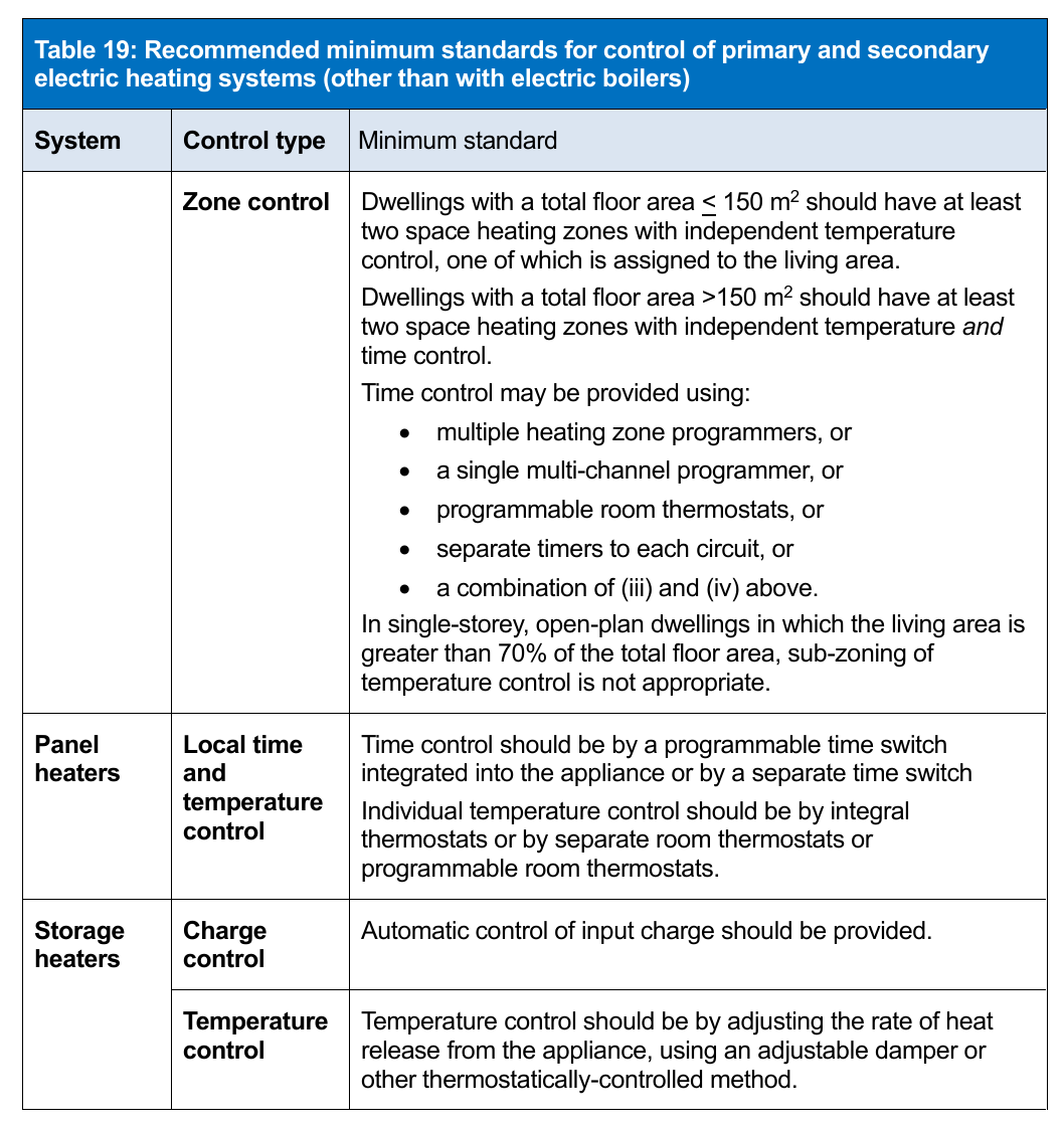
Section 6: Solid fuel heating
#Source page 51
6.1 Scope of guidance
This section provides guidance on meeting the energy efficiency standards in the building regulations for the following types of solid fuel heating appliances and systems used to deliver primary and secondary heating:
•batch-fed open fires
•batch-fed and automatic-feed dry room heaters/stoves
•batch-fed log and multi-fuel appliances
•automatic-feed pellet stoves with and without boilers
•batch-fed and automatic-feed room heaters with boilers
•batch-fed cookers with boilers not exceeding 7.5 kW
•batch-fed independent boilers and automatic-feed solid mineral, wood pellet, wood chip and wood log fired independent boilers
•central heating systems using certain types of solid fuel appliances.
The guidance covers the following types of solid fuel: coal, solid mineral fuel, dual-fuel, wood logs, wood pellets and wood chips.
Note: guidance is only given for solid mineral fuel as a component of dual fuel appliances.
6.2 Solid fuel appliances for primary heating
Solid fuel appliances provided as part of new systems or as a replacement appliance in existing systems for primary heating in dwellings should have an efficiency (gross calorific value) not less than specified in Table 20 for that category of appliance.
6.3 Central heating systems using certain types of solid fuel appliances
This section provides guidance on the following types of solid fuel appliance used to deliver primary heating as part of a central heating system:
•batch-fed open fires with high output boilers (appliance types D1 to D4 in Table 21)
•batch-fed and automatic-feed room heaters and stoves with boilers (appliance type F in Table 21)
•batch-fed cookers with boilers (appliance type G2 in Table 21)
•batch-fed independent boilers and automatic-feed anthracite, wood log, wood pellet and wood chip-fired independent boilers (appliance types J2 & J5 in Table 21).
Unless stated otherwise, the guidance applies equally to appliances that burn wood, wood pellets, house coal, manufactured smokeless fuels and anthracite.
Page 52
#Source page 52
Table 20: Solid fuel appliance categories and recommended minimum efficiencies Category1
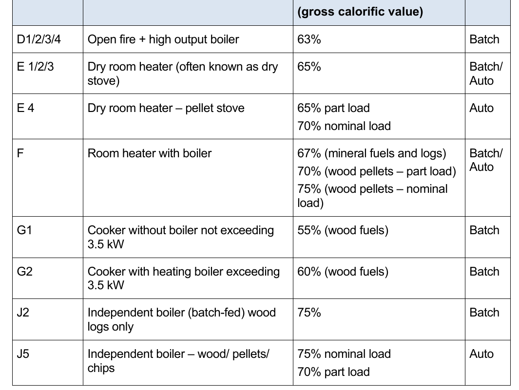
Note: Refers to the categories as set out in HETAS’ The Official Guide to HETAS Approved Products and Services, 2017.
For central heating systems with a solid fuel appliance installed as part of a new system or as a replacement component in an existing system:
a.the appliance should be from HETAS categories D, F, G and J in Table 21 and have a minimum efficiency (gross calorific value) which is not less than the value specified for its category
b.the ratio of room heat to water heat should be appropriate for the room and total property.
c.circulation, fuel storage, hot water storage, system preparation, water treatment and commissioning should be to the standards in Table 21
d.control of heating and hot water circuits should be to the standards in Table 22
e.vessel and pipework insulation as set out in Section 9.
Page 53
#Source page 53
| Table 21: Recommended minimum standards for system circulation, fuel storage, hot water storage, system preparation and commissioning for solid fuel central heating | |
| Minimum standard | |
| System circulation | The manufacturer’s instructions on the sizing and positioning of heat leak radiators should be followed. |
| Fuel storage | Provision should be made for storage of reasonable quantities of fuel in a convenient and dry location. The size of the storage will depend upon the requirement of the house. Refer also to guidance set out under standards 3.23 and 3.24 in section 3 (environment). |
| Hot water storage | Vented hot water storage vessels should comply with the heat loss and heat exchanger requirements of BS 1566-1:2002 or BS EN 12897 as appropriate. Copper hot water storage combination units should comply with BS 3198. Unvented hot water storage system products should comply with BS EN 12897:2006 or an equivalent standard. Unvented systems should not be used with gravity circulation. The standing heat loss for all hot water storage vessels should not exceed the relevant value from Table 28 in Section 9. All hot water storage vessels should carry a label with the following information: • type of vessel • nominal capacity in litres • standing heat loss in kWh/day • type of vessel • heat exchanger performance in kW. Vented copper hot water cylinders should carry clear labelling on the product such as a BSI Kitemark, registered firm status or reference to an equivalent quality control scheme. |
| System preparation and water treatment | Central heating systems should be thoroughly cleaned and flushed out before installing a new boiler. During final filling of the system a chemical water treatment formulation should be added to the primary circuit to control corrosion and the formation of scale and sludge. Reasonable provision would be to follow the guidance on how to prepare and commission systems given in BS 7593:2019 – ‘Code of practice for treatment of water in domestic hot water central heating systems’. Installers should also refer to the boiler manufacturer’s installation instructions for appropriate treatment products and special requirements for individual boiler models. Where the mains total water hardness exceeds 200 parts per million, provision should be made to treat the feed water to water heaters and the hot water circuit to reduce the rate of accumulation of limescale. |
Page 54
#Source page 54
| Table 21: Recommended minimum standards for system circulation, fuel storage, hot water storage, system preparation and commissioning for solid fuel central heating | |
| Minimum standard | |
| Commiss- sioning | On completion of the installation of a boiler or hot water storage system, together with associated equipment such as pipework, pumps and controls, the equipment should be commissioned in accordance with the manufacturer’s instructions. These instructions will be specific to the particular boiler or hot water storage system used. The installer should explain fully to the user how to operate the system in an energy efficient manner, and behind any user manuals provided by manufacturers. |
Supplementary information:
System circulation – Most solid fuel central heating systems require a heat leak radiator to dissipate heat from the smouldering fire bed. This is commonly the bathroom towel-rail and a thermosiphon system may be used for this circuit. In some cases, a fully pumped system reduces efficiency and should not be used.
System preparation and water treatment - Limescale can be controlled by the use of chemical limescale inhibitors, combined corrosion and limescale inhibitors, polyphosphate dosing, electrolytic scale reducers or water softeners. The relevant standard for water treatment is BS 7593:2019 – ‘Code of practice for the preparation, commissioning and maintenance of domestic central heating and cooling water systems’. Manufacturers should be consulted for advice, paying particular attention to dosage levels.
Special radiator valves are available that will seal off the radiator as well as the heating circuit to prevent loss of inhibitor when removing a radiator for service or maintenance.
A filter can also be fitted to the central heating circuit to help maintain the efficiency and reliability of the system.
Commissioning - Only persons who are competent should carry out the installation, e.g. installers who are registered with HETAS. Such persons will certify that they have carried out installation and commissioning in accordance with requirements in the building regulations and in the manufacturer’s instructions (which may be more stringent).
| Table 22: Recommended minimum standards for control of solid fuel central heating systems | |
| Topic | Minimum standard |
| All appliances, except open fires | |
| Burning rate | Automatic control of the burning rate. |
| Automatic-feed appliances | |
| Zoning | Dwellings with a total floor area ≤ 150 m² should have at least two space heating zones with independent temperature control, one of which is assigned to the living area. Dwellings with a total floor area > 150 m² should have at least two space heating zones with independent temperature and time control. |
Page 55
#Source page 55
| Table 22: Recommended minimum standards for control of solid fuel central heating systems | |
| Topic | Minimum standard |
| For single-storey, open-plan dwellings in which the living area is greater than 70% of the total floor area, sub-zoning of temperature control is not appropriate. | |
| Time control of space and water heating | Time control of space and water heating should be provided by: • a full programmer with separate timing to each circuit, or • two or more separate timers providing timing control to each circuit, or • programmable room thermostats to the heating circuits, with separate timing of the hot water circuit. |
| Temperature control of space heating | Separate temperature control of zones within the dwelling should be provided using: • room thermostats or programmable room thermostats in all zones, or • a room thermostat or programmable room thermostat in the main zone, and individual radiator controls such as thermostatic radiator valves (TRVs), or • a combination of i. and ii. above. |
| Temperature control of domestic hot water | A cylinder thermostat and a zone valve or three-port valve should be fitted to control the temperature of stored hot water. Non-electric hot water controllers should not be used. Where permitted by the manufacturer, the cylinder thermostat should be wired to provide a boiler interlock. |
Supplementary information
Boiler interlock, provided by a wiring arrangement to prevent the system from operating when there is no demand for heat, should only be fitted if recommended by the manufacturer.
In some simple batch-fed or automatic appliances (without heat stores or without automatic ignition), it is not possible to switch off the heat output completely, but the appliance output can be lowered to a minimum to reduce fuel consumption.
In most solid fuel systems, the room thermostat will switch off the pump, which in turn will cause the boiler to operate at minimum output.
Some automatic solid fuel systems can be fitted with weather compensation, and incorporate multi- zone control. It is important to seek guidance from the manufacturer, especially if the heating package is to include other fuels.
Controls may be provided by any boiler management control system that meets the specified zoning, timing and temperature, and boiler interlock control requirements.
The level of sophistication should generally be appropriate to and compatible with the appliance. The highest levels are only appropriate to appliances with automatic ignition.
As far as it is practicable and economic to do so when working on existing systems, controls should be upgraded to the levels defined for new systems.
Section 7: Heat networks
#Source page 56
7.1 Scope of guidance
This section provides guidance on the specification of systems within dwellings served by a heat network, to meet relevant energy efficiency requirements in the building regulations.
The Heat Networks (Scotland) Act 2021 defines a heat network as a district heating network or communal heating system distributing thermal energy from one or more sources to more than one building or one building comprising more than one building unit respectively. This section will be updated over time to reflect relevant regulatory provisions introduced under the above Act or under the Energy Securities Bill due to be introduced into UK Parliament in 2022. See section 7.3 for supplementary information on this topic.
Where heat is supplied from an external source, metering requirements for individual dwellings is required under The Heat Network (Metering and Billing) Regulations 2014.
7.2 Heat network connections
For new connections to a heat network, the design temperature difference for the network heating primary circuit should be greater than 20 ºC. Heat pump-led heat networks may, however, need to run at a lower temperature difference.
Variable volume control systems should be used to reduce the volume of water and the pressure difference required from the pumps under part load.
Provisions at the dwelling should be in accordance with the following:
a.control systems in Table 23
b.domestic hot water production in Table 24
c.Refer to Section 9 for further information on insulation of hot water storage vessels, and pipework.
| Table 23: Recommended minimum standards for control of systems within dwellings connected to a heat network | |
| Control type | Minimum standard |
| Zoning | Dwellings with a total floor area ≤ 150 m² should have at least two space heating zones with independent temperature control, one of which is assigned to the living area. Dwellings with a total floor area > 150 m² should have at least two space heating zones with independent temperature and time control. |
| Time control of space heating | Time control of space heating may be provided by: • a full programmer, or • two or more separate timers providing timing control to each zone, or • programmable room thermostats to the heating circuits. |
Page 57
#Source page 57
| Table 23: Recommended minimum standards for control of systems within dwellings connected to a heat network | |
| Control type | Minimum standard |
| For dwellings with a total floor area >150 m², time control for the separate space heating zones can be provided using: • multiple heating zone programmers, or • a single multi-channel programmer. | |
| Temperature control of space heating | Separate temperature control of zones within the dwelling should be provided using: • room thermostats or programmable room thermostats in all zones, or • a room thermostat or programmable room thermostat in the main zone, and individual radiator controls such as thermostatic radiator valves (TRVs) on all radiators in the other zones, or • a combination of (i) and (ii) above. |
| Temperature control of domestic hot water | Temperature control of the domestic hot water service should be provided using two-port control valves, either electrically operated or direct-acting. |
| Limitation of maximum flow rate into building or dwelling | The maximum design flow rate into the dwelling heating system should be limited by suitable control and balancing valves to maintain the overall balance in the network and to avoid excessive pumping energy. |
Supplementary information:
In single-storey, open-plan dwellings in which the living area is greater than 70% of the total floor area, sub-zoning of temperature control is not appropriate.
Where the hot water is produced instantaneously, such as with a plate heat exchanger, time control is only required for space heating zones.
Time control of domestic hot water heating using a cylinder is not considered essential for heat networks and could be a disadvantage with CHP-based systems, increasing the morning peak demand and hence causing more use of the boiler than necessary.
Control valves and TRVs should be two-port type to reduce flow rates under part load.
Differential pressures across control valves and TRVs should be limited to ensure that the control valves work effectively and maintain shut-off.
Where instantaneous heat exchangers are used the control valve should be selected to maintain steady temperatures (<+/- 5ºC) for a range of draw-off rates and primary differential pressures. To reduce the incidence of scalding, the control valve should shut off the primary flow when there is no domestic hot water draw off. A small intermittent flow is an advantage to maintain the temperature within the heat exchanger so as to provide more rapid heat up.
7.3 Supplementary Guidance
#Source page 58
| Table 24: Recommended minimum standards for domestic hot water production, storage and water treatment, heat meters and commissioning for dwellings connected to heat networks | |
| Minimum standard | |
| DHW production and storage | The hot water system should be controlled using variable volume control designed to maintain low return temperatures in the primary network heating circuit. |
| Heat meters | Systems should be designed to accommodate heat meters for each dwelling at the point of installation. |
| Commiss- ioning | Heat network connections should be commissioned to optimise the use of energy for pumping. The flow rates in individual heat emitters should be balanced using appropriate return temperatures or by using calibrated control valves. The systems within the dwellings should be demonstrated to the resident and suitable information provided on the operation of the controls. |
Supplementary information:
Hot water can be produced in four ways for dwellings connected to a heat network:
•in individual dwellings using indirect storage cylinders
•in individual dwellings using instantaneous plate heat exchangers
•from the network using storage calorifiers with either an indirect coil or an external plate heat exchanger
•from the network using an instantaneous plate heat exchanger.
In selecting the system, consideration should be given to:
•the impact on return temperatures in the heat network
•the impact on flow rates in the heat network
•the impact on heat demand profiles and compatibility with the heat source
•standing losses from storage cylinders/ calorifiers and the impact on energy use
•the quality of service provided in terms of flow rate and temperature control
•the advantages of having local storage in terms of security of supply.
Where the network is extensive and hot water production is centralised, a two-stage water heating system can be used to deliver low return temperatures. In this design the return water from the space heating circuit is used to pre-heat the cold feed to the domestic hot water.
7.3 Supplementary Guidance
Future regulation of heat networks.
As set out in the Heat Networks Delivery Plan, licensing and consenting will be the mainstay of the regulatory system for heat networks in Scotland which we aim to be in place by early 2024, helping to ensure a high quality and efficient service as well as
Page 59
#Source page 59
ensuring that networks are well sighted and aligned with the delivery of both national and local objectives. Licences will be required by companies wishing to develop and operate heat networks in Scotland. A single licence will be required per company operating in Scotland. Consents will be needed for each individual heat network.
It is anticipated that both licences and consents will be required by both new and existing networks, with exemptions and abeyances in place to ensure the system is proportionate.
A key benefit of the licensing regime is that it will ensure that existing networks (that were operational before the licensing regime) will move to zero emission heat sources. Details on the Heat Network Decarbonisation Plans that we propose, that licence holders who operate existing networks in Scotland will be required to prepare and then implement, are provided in the Heat Networks Delivery Plan and will be built on in a subsequent consultation relating to the heat networks regulatory regime.
The Heat Networks Delivery Plan sets out that from the time the legislative framework is in place, new heat networks, and additional plants for extensions, will need to be powered using low and zero emissions heat sources. Heat from sources such as surplus or waste heat, electric heat pumps, solar thermal or plant using green hydrogen would be considered low and zero emissions. Considering feedback from network developers that are aiming to deliver zero emissions systems, in order to ensure that networks can remain resilient and affordable, we will require that, from the point that the regulatory system is in place in 2024, the vast majority of heat for new networks is to be provided from low and zero emission sources. However, in the near term a small percentage of annual heat provided through some networks may need to be sourced from natural gas for the purposes of peaking and backup. The exact percentage will be determined on a case by case basis and the need will have to be evidenced, while showing other options have been explored. New networks will be required to have a plan as to how that percentage is expected to reduce over time, with significant progress made by a set year. This could for example be by 2035.
Additionally, UK Government has set out in Heat Networks: Building a Market Framework – Government Response that they intend to introduce a general authorisation regime that will enable Ofgem to enforce consumer protection rules. This will require that entities supplying heat through heat networks (that is, having a contractual agreement with customers to supply heat) and entities operating heat networks will have to be authorised to do so. It is expected that these measures will be introduced through the Energy Securities Bill announced in the Queen’s speech in May 2022. Scottish Government continues to work with the UK Government to ensure consumer protection and licensing can both be dealt with by Ofgem in Scotland.
Section 8: Underfloor heating
#Source page 60
8.1 Scope of guidance
This section provides guidance on the specification of underfloor heating systems in new dwellings to meet relevant energy efficiency requirements in the building regulations.
The guidance covers the use of hot water pipes or electric heating elements as the underfloor heat source.
8.2 Underfloor heating in new dwellings
Underfloor heating in new dwellings should meet the minimum standards for:
a.system control and safe operating temperatures in Table 25.
b.floor insulation and system design to minimise distribution losses in Table 26.
c.in the case of electric underfloor heating systems in new dwellings, construction and controls in Table 27.
| Table 25: Recommended minimum standards for control of wet and electric underfloor heating systems | |
| Element | Minimum standard All floor heating systems, should be fitted with controls to adjust the operating temperature. To prevent damage to floors and occupant discomfort, the temperature of the flow water from warm water systems connected to a high temperature (>60 °C) heat source should be controlled using: • multi-port mixing valves and thermo-mechanical or thermo- electric actuators • a separate high-limit thermostat. Electric floor heating systems should comply with the rules in the current edition of BS 7671 – ‘Requirements for electrical installations’, ‘Section 753, Floor and ceiling heating systems’ for protection against electric shock and thermal effects, and for selection and installation of equipment. |
| Room temperature control: Wet and electric underfloor heating systems | Each room should have its own thermostat, sensor or programmable thermostat. Electric underfloor heating systems should have a manual override feature. Where two adjacent rooms have a similar function – for example a kitchen and a utility room – it may be appropriate for both rooms to share a single temperature control. |
Page 61
#Source page 61
| Table 25: Recommended minimum standards for control of wet and electric underfloor heating systems | |
| Element | Minimum standard |
| Time control: Wet and electric underfloor heating systems | Dwellings with a total floor area > 150 m² should have at least two space heating zones with independent on/off time and temperature control. For single storey open-plan dwellings in which the living area is greater than 70% of the total floor area, sub-zoning of temperature control is not appropriate. Thick screed floor heating systems (>65 mm) should have facilities to automatically adjust the room temperature to a lower level at night or when the room is unoccupied. |
| Boiler control: Wet underfloor heating systems only | The heating system controls should be connected so that when there is no demand for heat, the heat source and pump are switched off. |
| Table 26: Recommended minimum standards for floor insulation and minimising distribution losses in wet and electric underfloor heating systems | |
| Element | Minimum standard |
| Exposed ground floors | Ground floors and those in contact with the outside should be insulated to limit heat losses to not more than 10 W/m². Floor heating systems intended for intermittent or cyclical operation or installed over unheated rooms should be separated from the structural floor by a layer of thermal insulation with a thermal resistance of at least 1.25 (m².K)/W. |
| Intermediate floors with heated rooms below: wet systems | The intermediate floor should have a separating layer of system thermal insulation with thermal resistance as in row one above, or not less than 0.75 (m².K)/W as specified in BS EN 1264-4. |
| Intermediate floors with heated rooms below: electric systems | The intermediate floor should have a separating layer of system thermal insulation with thermal resistance as in 1.0 b above, or not less than 0.5 (m².K)/W. |
| System design to minimise distribution losses | Distribution pipework which does not provide useful heat to a room should be insulated to the relevant value from the table below. |
| System commissioning and corrosion protection | Commissioning warm water floor heating systems should be carried out in accordance with BS EN 1264-4. After testing and flushing with clean water, the system circulating fluid should be treated with a suitable corrosion inhibitor |
Page 62
#Source page 62
| Table 26: Recommended minimum standards for floor insulation and minimising distribution losses in wet and electric underfloor heating systems | |
| Element | Minimum standard |
| Control of oxidation, biofilm, scale and sludge in warm water heating systems | approved by the tube manufacturer and complying with BS 7593:2019 and applied strictly in accordance with the additive manufacturer’s instructions. |
| Table 27: Recommended minimum standards for construction and control of electric underfloor heating systems | ||
| System and element | Minimum standard | |
| Electric storage systems with individual room or programmable thermostats and low tariff anticipatory controls | Construction | Electric cable underfloor heating night energy storage systems should have a 65 mm minimum thickness screed for correct operation. retain A minimum of 20% of the floor area of the dwelling should have fast response systems such as panel heaters. |
| Controls | Controls should be installed which are designed to modify the input charge in response to both of the following: • the room thermostat • floor temperature sensing Programmable room thermostats with an override feature should be provided for all direct-acting zones of the system with air and floor temperature sensing capabilities to be used individually or combined. | |
| Electric cable, direct-acting (non-storage) systems with individual room timer or thermostat control in screeded floors | Construction | Direct-acting electric underfloor heating cables should be installed within screeds of thickness not exceeding 60 mm. All heated floors should be insulated in accordance with Table 26 |
| Controls | Programmable room thermostats with a manual override feature for all heating zones with air or floor temperature sensing capabilities should be used individually or combined. |
Page 63
#Source page 63
| Table 27: Recommended minimum standards for construction and control of electric underfloor heating systems | ||
| System and element | Minimum standard | |
| Electric cable, direct-acting systems with individual room timer or thermostat control in timber floors | Construction | Direct-acting electric underfloor heating cables installed below floor boards in voids between floor joists should be insulated in accordance with Table 26. |
| Controls | Programmable room thermostats with a manual override feature should be provided to control space temperature and limit floor void temperature for safety and comfort in each area. | |
| Under-tile electric floor heating systems | Construction | Direct-acting electric underfloor heating cables should be provided with a pre-fabricated mattress, or equivalent IEC 60800:2009 approved heating cable product, of thickness less than 4 mm encapsulated in tile bedding adhesive or mortar, below a ceramic or other equivalent floor finish on a thermally resistive insulation layer as in Table 26. |
| Controls | Programmable room thermostats with a manual override feature should be provided to control space temperature and limit floor temperature for safety and comfort in each area. |
Section 9: Vessel, pipework and ductwork insulation
#Source page 64
9.1 Scope of guidance
This section gives guidance on insulating pipework and ducting serving space heating, hot water and cooling systems in new and existing buildings to meet relevant energy efficiency requirements in the building regulations.
The insulation of vessels, pipework and ducting is essential to minimise heating system heat losses and cooling system heat gains. For cooling systems, it is also important to ensure that the risk of condensation is adequately controlled.
The guidance in this section covers insulation for the following elements serving space heating, domestic hot water and cooling systems:
•domestic hot water storage vessels.
•pipework: direct hot water, low, medium and high temperature heating, and cooled
•ductwork: heated, cooled and dual-purpose heated and cooled.
9.2 Insulation of domestic hot water storage vessels
Domestic hot water storage vessels should be insulated to limit standing heat losses to the values no greater than those set out in Table 28.
Table 28: Recommended maximum heat losses from DHW storage vessels1
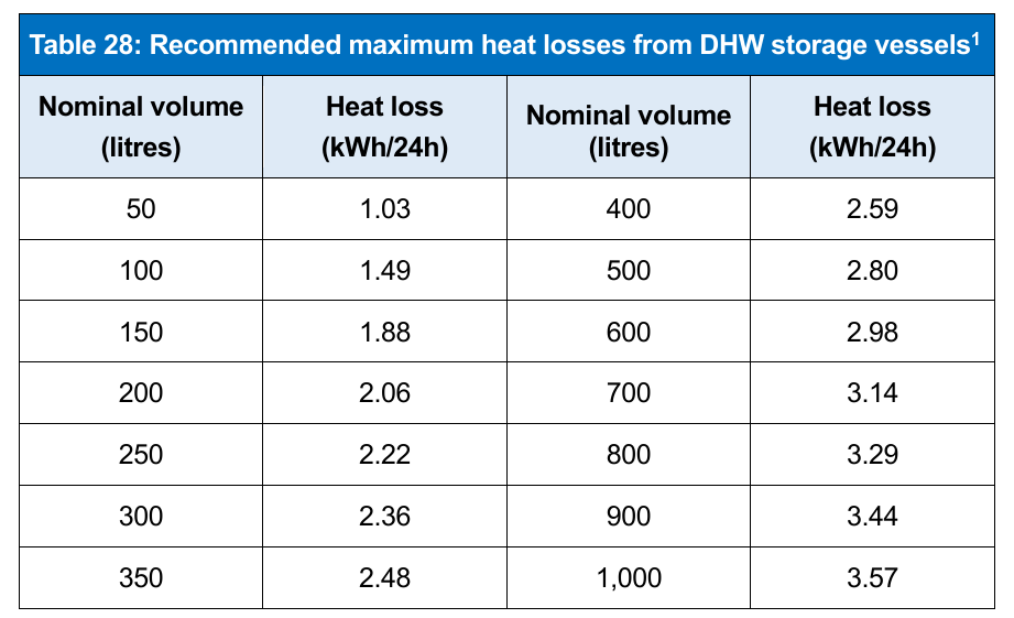
Note: The heat loss from cylinders larger than 1000 litres should not exceed (16.66 + 8.33 x V 0.4)/(1000 x 24) where V is the volume in litres.
Hot water storage vessels should comply with all of the following.
a.Copper hot water storage combination units should comply with BS 3198.
9.3 Insulation of pipes and ducts in new and existing buildings
#Source page 65
b.Vented cylinders should comply with the heat loss and heat exchanger requirements of BS 1566-1 or BS EN 12897 as appropriate.
c.Unvented hot water storage system products should comply with BS EN 12897.
d.All hot water vessels should carry a label with the following information:
•type of vessel (vented, unvented, combination unit or thermal store)
•nominal capacity in litres
•standing heat loss in kWh/day
•heat exchanger performance in kW
•reference to product compliance with relevant standard (e.g. BS 1566, BS 12897) and logos of accreditation bodies as required.
9.3 Insulation of pipes and ducts in new and existing buildings
To optimise the effectiveness of the supply of heat or cooling, hot water pipework and warm or cold air ductwork should be insulated in all areas inside and outside the building.
Insulation of pipes and ducts serving heating and cooling systems should meet the following recommended minimum standards.
Direct hot water and heating pipework
Pipework serving space heating and hot water systems should be insulated in all areas outside of the heated building envelope. In addition, pipes should be insulated in all voids within the building envelope and within spaces which will normally be heated, if there is a possibility that those spaces might be maintained at temperatures different to those maintained in other zones. The guiding principles are that control should be maximised and that heat loss from uninsulated pipes should only be permitted where the heat can be demonstrated as ‘always useful’.
In a new system, all of the following new pipework should be insulated.
a.Primary circulation pipes for heating circuits where they pass outside the heated living space, including where pipework passes into voids.
b.All primary circulation pipes for domestic hot water.
c.All pipes that are connected to hot water storage vessels, for at least 1 metre from the point at which they connect to the cylinder.
d.All secondary circulation pipework that is kept hot by that circulation.
Where a new boiler or hot water storage vessel is installed, or where existing systems are extended, new or existing pipes, ducts and vessels that are accessible or exposed as part of the work should be insulated as for new systems. Replacement hot water storage vessels should be insulated as for new systems.
It is recognised that complete insulation will sometimes not be possible, where such services pass through or around structural building components, floor joists, for example, or where
Page 66
#Source page 66
existing systems are wholly or partially retained as part of conversion works. In such cases, insulation should be fitted as for new systems as far as is reasonably practicable.
Insulation should be designed so that the permissible heat losses in BS 5422 for hot water services at 60 ºC are not exceeded as shown in Table 29 for different pipe sizes. Insulation thickness should be calculated in accordance with BS EN ISO 12241.
| Table 29: Minimum pipework insulation thicknesses for hot water services and space heating applications in low temperature hot water systems | |
| Nominal internal pipe diameter (mm) | Minimum insulation thickness¹ (mm) for low temperature hot water systems |
| ≤ 10 | 5 |
| ≤ 25 | 10 |
| ≤ 50 | 15 |
| ≤ 100 | 20 |
Notes:
1.Thicknesses apply for low-emissivity faced insulation with a thermal conductivity of 0.025 W/(m.K) or better. Otherwise consult BS 5422.
Heating and cooling ductwork
Where not designed to contribute to the heating or cooling of the space it passes through, ducting should be insulated along its whole length in order to provide the necessary means of limiting heat gains or heat losses.
The heat losses or gains per unit area should not exceed the values in Table 30. Where ducting may be used for both heating and cooling, the limits for chilled ducting should be adopted since these are more onerous (heat gains are shown as negative values).
Additional insulation may be required to provide adequate condensation control.
| Table 30: Recommended maximum heat losses and gains for ducts delivering air for heating and/or cooling | ||
| Heating duct | Cooling / dual-purpose duct | |
| Heat transfer (W/m²) | 16.34 | -6.45 |
| Indicative insulation thickness (mm) | 21 | 36 |
Note: Thicknesses apply for low-emissivity faced insulation with a thermal conductivity of 0.025 W/(m.K) or better. Otherwise consult BS 5422. Insulation thicknesses should be calculated according to BS EN ISO 12241
External pipework for district heat networks
Pipework for district heat networks within the curtilage of a building should be insulated to meet BS EN 253 for pre-insulated pipes or equivalent performance for conventionally insulated pipes.
Where pipework is above ground, the performance of the pipe insulation should be at least as high as the insulating performance of below-ground pipework.
Section 10: Mechanical ventilation
#Source page 67
10.1 Scope of guidance
This section provides guidance on the specification of mechanical ventilation systems in dwellings to meet relevant energy efficiency requirements in the building regulations.
The guidance covers the following types of mechanical ventilation:
•intermittent extract
•continuous extract
•continuous supply and extract with or without heat recovery.
10.2 Energy efficiency of mechanical ventilation systems
Mechanical ventilation systems should:
a.follow the guidance in Building Standards Division ‘Annex 3A - Domestic Ventilation Guide’; and be commissioned so that spaces are provided with ventilation to the levels required under standard 3.14.
b.meet the minimum standards for specific fan power, heat recovery efficiency and controls in Table 31; and
| Table 31: Recommended minimum standards for mechanical ventilation systems | |
| Element | Minimum standard |
| Fan power | Mechanical ventilation systems should be designed to minimise electric fan power. The specific fan power (SFP) should be no worse than: • 0.5 W/(l/s) for intermittent extract ventilation systems • 0.7 W/(l/s) for continuous extract ventilation systems • 0.5 W/(l/s) for continuous supply ventilation systems • 1.5 W/(l/s) for continuous supply and extract with heat recovery ventilation systems. |
| Heat recovery efficiency | The heat recovery efficiency of mechanical ventilation systems incorporating heat recovery should be no worse than 73%. |
| Controls | Controls may be manual (i.e. operated by the occupant) or automatic as suits the installed system. |
10.3 Packaged ventilation systems
All packaged ventilation systems providing both supply and extract ventilation should be fitted with all of the following, where this does not conflict with the intended ventilation strategy or design infiltration rate:
Page 68
#Source page 68
a.Heat recovery system with summer bypass (to bypass the heat exchanger or to control heat recovery performance).
b.Variable speed controller.
Section 11: Space and comfort cooling
#Source page 69
11.1 Scope of guidance
This section provides guidance on the specification of fixed mechanical comfort cooling systems and fans in dwellings to meet relevant energy efficiency requirements in the building regulations.
Dwellings should always be designed to avoid or minimise the need for cooling through the appropriate use of solar control, secure ventilation and thermal mass. Reference should also be made to Standard 3.28 which sets our action to assess and mitigate summertime overheating risk in new dwellings. Active cooling systems in new dwellings should only be present where all practical options for passive cooling have been applied and this demonstrated via Dynamic Thermal Assessment modelling.
11.2 Air-cooled and water-cooled air conditioners
The specification of space cooling systems should be based on an appropriate heat gain calculation for the building, based on CIBSE Design Guide A and by following the manufacturer’s guidance. Systems should not be significantly oversized.
Cooling systems in new and existing dwellings should meet the minimum standards for efficiency in Table 32.
| Table 32: Recommended minimum standards for comfort cooling | |
| Element | Minimum standard |
| System efficiency | The seasonal energy efficiency ratio of an air conditioner working in cooling mode should be a minimum of 4.0. |
| Controls | Comfort cooling/air conditioning systems should have both of the following controls. • For each control zone and for each terminal unit, it should be possible to independently control both the timing and temperature. • If both heating and cooling are provided in the same space, the controls should prevent them operating simultaneously. |
| Pipework | Exposed refrigeration pipework should be insulated and enclosed in protective trunking |
Note: for centralised cooling systems, follow the guidance in the Non-domestic Building Service Compliance Guide for Scotland.
Section 12: Solar water heating
#Source page 70
12.1 Scope of guidance
This section provides guidance on the specification of solar water heating for dwellings to meet relevant energy efficiency requirements in the building regulations.
The guidance in this section covers indirect solar systems with a collector area of less than 20 m 2 and solar heated water storage of less than 440 litres.
12.2 Indirect systems
Indirect solar heating systems installed as new systems and replacement systems should meet the minimum standards for:
•collector certification, identification and testing, collector primary loop transfer fluid, circulation pump power, heat-exchanger sizing, system control, solar pre-heated water storage, and system preparation in Table 39
•system labelling and commissioning in Table 40
•insulating pipes in a solar primary system in Table 41.
When work is carried out on an existing indirect solar hot water system, it is recommended that the system controls and insulation should be upgraded in line with the standards for new systems.
12.3Recommended minimum standards for indirect solar water heating
Allowance for collector shading
No minimum provision.
Note: solar collectors should be sited in unshaded locations wherever possible. Where this is unavoidable or in cases of significant or heavy shading or significant variance to the optimum orientation and tilt (i.e. normal pitch roofs facing between SE and SW), then an allowance for the loss of performance should be made when sizing the collector area according to the factors indicated in SAP 10 Appendix H.
Solar collector certification
Collectors should be independently certified to comply with all required tests for safety and thermal performance, and for reporting and identification according to BS EN 12975 and BS EN ISO 9806.
Primary circuit fluid
The transfer fluid in the collector primary loop should be chosen so as not to deposit limescale, sludge, ice or other solids that could either restrict circulation or impair the rate of heat transfer within the absorber.
Note: In secondary systems, measures to reduce the formation of limescale should be considered so that performance is not significantly affected.
Page 71
#Source page 71
Circulation pump power
The electrical input power of the primary pump in the solar system should be less than 50 W or 2% of peak thermal power of collector, whichever is the higher.
Heat-exchanger Sizing
The heat exchanger between a solar primary and secondary system should be sized so that not less than 0.1 m 2 or equivalent of heat exchanger area is provided per 1 m 2 of solar collector net absorber area.
Note: A heat exchanger reduces the possibility of clogging and deposition due to dirt, scale or similar impurities that could reduce the system performance.
Heat exchangers and store connections should be sized and located to promote a low return temperature to the solar collector. Solar heat exchangers are often sized larger than those usually used on gas- or oil-based primary systems owing to the lower temperature of transfer.
System controls
Solar domestic hot water (DHW) system controls should be fitted to:
•maximise the useful energy gain from the solar collectors
•minimise the accidental loss of stored energy
•ensure that hot water produced by back-up sources is not used when adequate solar pre-heated water is available
•provide a means to control the adverse effects of excessive temperatures and pressures
•where a separate DHW heating appliance is pre-heated by a solar system, the appliance should be controlled to add no extra heat if the target temperature is met from the solar pre-heated vessel
•inform the end user of the system’s correct function and performance at all times.
Solar pre-heated water storage
Vented hot water storage vessels should comply with the heat loss and back-up heating heat exchanger requirements of BS 1566-1:2002 or BS EN 12897 as appropriate.
Unvented hot water storage system products should comply with BS EN 12897:2006.
Primary storage systems should meet the insulation requirements of sections 4.3.1 or 4.3.2 of the Hot Water Association – ‘Performance specification for thermal stores’.
Note: vented copper hot water cylinders should carry clear labelling on the product such as a BSI Kitemark, registered firm status or reference to an equivalent quality control scheme.
Vented cylinders which are not of copper construction should be labelled as complying with the heat loss and heat exchanger requirements of BS 1566-1:2002.
Due to the higher than normal storage temperatures in primary stores, it is very important that they are well insulated.
Page 72
#Source page 72
Volume of solar pre-heated water
The ratio of solar heated water storage volume to collector area should be either of the following:
•the dedicated solar storage volume, Vs , should be a minimum of 25 litres per net square metre of the solar collector absorber area.
•alternatively, V s should be a volume which is equivalent to at least 80% of the daily hot water demand, V d (as defined by SAP 10).
Note: collector area is measured as effective aperture or net absorber area, whichever is smaller. A separate pre-heat storage vessel should be considered wherever possible.
System preparation and water treatment
New build
•Solar primary circuits should be thoroughly cleaned with an appropriate cleaner and flushed through with solar heat transfer fluid before filling with the solar heat transfer fluid.
•Systems should be filled with a heat transfer fluid containing a volatile inhibitor package, capable of protecting the system from frost and corrosion at all operating temperatures.
•Installers should refer to the equipment manufacturer’s installation instructions for appropriate treatment products and special requirements for individual appliance models.
•Where mains water is used to fill the solar primary circuit and the total water hardness exceeds 200 parts per million, provision should be made to reduce the limescale.
Existing installations
•Solar thermal systems should be cleaned with an appropriate cleaner formulated to remove build-up of degradation films from exhausted heat transfer fluids, then flushed through with fresh solar heat transfer fluid.
•Systems should be filled with a heat transfer fluid containing a volatile inhibitor package, capable of protecting the system from frost and corrosion at all operating temperatures.
•Installers should refer to the equipment manufacturer’s installation instructions for appropriate treatment products and special requirements for individual appliance models.
12.4Recommended minimum standards for labelling, commissioning and documentation for solar hot water systems
Labelling of solar collectors and hot water stores
All solar collectors should have a visible and durable label displaying all information required according to BS EN 12975 and including at least the following:
Page 73
#Source page 73
•name of manufacturer
•collector type
•serial number
•year of production
•gross area of collector
•aperture area of collector
•net absorber area of collector
•maximum operation pressure
•stagnation temperature at 1,000 W/m2 and 30 °C ambient
•volume of heat transfer fluid
•weight of empty solar collector.
All hot water storage vessels should carry a label with the following information:
•manufacturer’s name
•nominal overall capacity in litres
•dedicated solar capacity in litres
•standing heat loss in kWh/day
•type of vessel
•back-up heating heat exchanger performance in kW (where present)
•solar heating heat exchanger performance in kW.
Note: In addition to the minimum provision for labelling of hot water storage vessels, labelling with the following information is also recommended:
•Total net fluid content of secondary volume normally heated by each heat exchanger, where present (+/- 1.0 litre).
•The type, fluid content, maximum pressure and surface area of all heat exchangers.
Commissioning Certificate
A signed and dated commissioning certificate should be completed to confirm the equipment has been correctly installed and to record key safety and operational features.
As a minimum, the commissioning certificate should record the following details of the solar system:
•net or aperture area of solar collector
•minimum ambient temperature without freeze damage to components
•location of device and method for controlling over-pressure
•location of the electrical isolating switch
•type of circulation fluid
•circulation rate of collector circuit
•location of device for protecting against overheating of solar heated water.
Page 74
#Source page 74
Note: a separate certificate is required to cover the installation and commissioning of the hot water storage vessels and appliances within a solar DHW system.
A commissioning engineer should be a competent person who can personally testify by signature and date that the equipment has been commissioned.
Written Information
Information provided to the dwelling owner or user should include:
•user manual;
•warranty information;
•a recommended maintenance schedule;
•commissioning certificate; and
•full contact details of the installer.
12.5Recommended minimum standards for insulation of pipework in solar hot water systems
All pipes of a solar primary system should be insulated throughout the length of the circuit to limit heat losses between collector and hot water vessel.
All other pipes connected to hot water storage vessels, should be insulated for at least 1 metre from their points of connection to the cylinder, or insulated up to the point where they become concealed.
Pipe insulation should be suitably rated for the maximum foreseeable pipe temperature applicable, and where external also be resistant to vermin attack and climatic degradation.
A solar hot water system can have a pipe service temperature of 150 °C. The insulation material should be specified to accommodate the normal operating temperature, such as EPDM rubber, mineral fibre, or rigid polyurethane. Insulation of a solar primary circuit should limit heat loss to no greater than achieved by a material with a thickness of 87% of the pipe diameter with a conductivity of 0.038 W/(m.K), calculated at 50 °C mean flow temperature.
In a dwelling that already has a solar hot water system, it is recommended that the insulation should be upgraded in line with these minimum provisions where significant work, such as change of solar storage, is carried out.
Useful references:
Energy Efficiency Best Practice in Housing CE131 – ‘Solar water heating systems. Guidance for professionals, conventional indirect models’.
Microgeneration Certification Scheme standard MIS3001 - ‘Requirements for contractors undertaking the supply, design, installation, set to work, commissioning and handover of solar heating microgeneration systems’.
HVSH ‘Solar heating design and installation guide’. 2016
Section 13: Lighting
#Source page 75
13.1 Scope of guidance
This section provides guidance on the specification of fixed internal and external lighting for new and existing dwellings to meet relevant energy efficiency requirements in the building regulations.
13.2 Key terms
Fixed external lighting means lighting fixed to an external surface of the dwelling supplied from the occupier’s electrical system. It excludes lighting in common areas of blocks of flats and in other communal accessways.
Circuit-watt means the power consumed in lighting circuits by lamps and, where applicable, their associated control gear (including transformers and drivers) and power factor correction equipment.
Light fitting means a fixed light or lighting unit that can comprise one or more lamps and lampholders, control gear and an appropriate housing. The control gear may be integrated in the lamp or located elsewhere in or near to the fixed light.
13.3 Internal and external lighting
Any fixed lighting should be designed to achieve lighting levels appropriate to the activity in the space. Light fittings may be either:
•dedicated fittings which will have separate control gear and will take only low energy lamps (e.g. pin based fluorescent or compact fluorescent lamps); or
•standard fittings supplied with low energy lamps with integrated control gear (e.g. bayonet or Edison screw base compact fluorescent lamps).
In many cases, it is likely that householders will be able to choose the lamp installed in the individual space, however, where fixed lighting is provided, spaces should be within an illuminance range recommended in design guidance and should not be over-illuminated.
Fixed internal lighting
All internal light fittings to have minimum luminous efficacy of 75 lamp lumens per circuit watt.
Local controls for separate control of each space or zone. Controls may be automatic, manual or a combination of both.
Fixed external lighting
Where fixed external lighting is installed, provide light fittings with the following characteristics:
•Automatic controls to switch off the luminaires in response to daylight.
•If the lamp efficacy is 75 lamp lumens per circuit watt or less external light fittings should have automatic controls which switch luminaires off in response to occupancy, otherwise manual control is acceptable.
Section 14: Micro-combined heat and power
#Source page 76
14.1 Scope of guidance
This section provides guidance on the specification of micro-combined heat and power (micro-CHP) packages for dwellings. It covers micro-CHP systems with an electrical output less than 5 kW e which are heat-led, capable of exporting electricity to the grid (see note below) and controlled in such a way as to avoid heat dumping.
14.2 Key terms
Heating plant emission rate (HPER) is the annual CO 2 emissions from fuel and power consumed by the heating plant, offset by the emissions saved as a result of any electricity generated by the heating plant, divided by the heat output over a year. It is measured in units of kg of CO 2 per kWh. To calculate HPER it is necessary to know the plant size ratio.
Note: The HPER includes any auxiliary space and water heating that may be necessary, i.e. it represents the performance of all heating plant needed to provide space and water heating service to the building, assuming a standard demand pattern.
Plant size ratio (PSR) is defined as the nominal heat output of the heating plant divided by the design heat loss (the average heat loss of the building on a cold day with a temperature differential of 24.2 °C). Note: For a given heat demand, the PSR determines the part-load condition for the heating plant.
14.3 Micro-CHP systems
Under SAP 10, the calculation of the overall energy and emission performance of new dwellings in Scotland now makes an assessment of the export component of any means of on-site generation of power. Use of micro-CHP should be heat-led and, for new homes, specification considered in this context.
The HPER of the micro combined heat and power system (micro-CHP) should be no greater than the emission rate of a regular boiler using the same fuel as the micro-CHP.
The HPER should be calculated using all of the following.
•The method in DEFRA’s ‘Method to Evaluate the Annual Energy Performance of Micro-cogeneration Heating Systems in Dwellings’.
•The performance data for the micro-CHP packaged according to BSI PAS 67.
•A plant size ratio as noted in clause 14.2 above.
Useful documents
Appendix N of SAP 10 - ‘Micro-cogeneration (or micro-CHP) and heat pumps’.
Microgeneration Certification Scheme standard, MIS 3007-2 – ‘Requirements for MCS contractors undertaking the design, supply, installation, set to work, commissioning and handover of a heating system containing a micro-cogeneration package or add-on units’.
‘Connecting a microgeneration system to a domestic or similar electrical installation’, Best Practice Guide, the Electrical Safety Council.
Section 15: Heating system circulators
#Source page 77
Circulators
Heating system glandless circulators up to 2.5 kW, both standalone and integrated in products provided with new systems or as replacements in existing systems in dwellings, should meet minimum standards for energy efficiency in accordance with The Ecodesign for Energy-Related Products Regulations 2010:
•standalone glandless circulators, other than those specifically designed for primary circuits of thermal solar systems and of heat pumps, should have an Energy Efficiency Index (EEI) no greater than 0.27.
•Standalone glandless circulators and glandless circulators integrated in products should have an Energy Efficiency Index (EEI) no greater than 0.23.
Section 16: Building Automation and Control Systems
#Source page 78
A Building Automation and Control System is a system comprising all products, software and engineering services that can support energy efficient, economical and safe operation of technical building systems through automatic controls and by facilitating the manual management of those building systems.
Where a Building Automation and Control System is installed in a new or existing dwelling, it should have appropriate control capabilities for the dwelling, based on the type of building, its expected use and potential energy savings. The system should be appropriately sized.
The system should be specified and installed according to the manufacturer’s instructions to ensure the overall performance of the system meets a reasonable standard.
For large or complex buildings, the guidance in the Non-domestic Building Services Compliance Guide should be followed.
Section 17 – Self-Regulating Devices
#Source page 79
17.1 Scope of guidance
This section provides additional guidance on the provision of self-regulating devices, such as room and emitter thermostats, in new and existing buildings to meet relevant energy efficiency requirements in the building regulations. These are cited in relation to heating system controls in a number of the previous sections.
17.2 Key terms
Self-regulating device means a device or system that automatically controls the output of heating and/or cooling emitters to independently control the temperature in each room or, (where justified, a heating zone) where heating and/or cooling is provided by a fixed building service.
17.3 Self-regulating devices
For heating and cooling systems in new buildings, each room or, where justified in accordance with guidance given below, heating zone should be provided with self-regulating devices for the separate control of heating in the room/zone.
Provision of self-regulating devices
Provision for self-regulating devices can be achieved by providing any of the following solutions:
•An individual networked heat emitter control for each emitter; or
•A thermostat in a room that the heating circuit serves, together with an individual self- regulating device for each heat emitter, such as a thermostatic radiator valve, on all heat emitters outside the room which contains the thermostat.
Thermostatic radiator valves should not be located in the same room as the thermostat.
•An individual room/ heating zone thermostat or fan coil thermostat for each room/heating zone.
•Any other controls which provide the same function as a self-regulating device.
Existing Buildings
For work in existing buildings, when a heat generator, such as a boiler, is replaced, if not already present, self-regulating devices should be installed, where technically feasible and economically feasible, for the separate control of heating in each room served by the heating appliance.
Measures which are not technically feasible include, but are not limited to:
•Buildings with very low heat demand (e.g. <10 W/m2).
•Homes with buffer zones for heat absorption or dissipation with high thermal mass.
Page 80
#Source page 80
Note that, in normal circumstances, the installation of thermostatic radiator valves in wet central heating systems is likely to be economically feasible.
Option to provide control at zone level
Alternatively, where justified below, heating may be controlled for each heating zone rather than individual rooms where any of the following apply:
•in open-plan spaces in which heating demand and patterns of use are similar across the whole space, sub-zoning of temperature control might not be appropriate. In such cases, the space should be considered as a single heating zone
•where two adjacent rooms have a similar function and heating requirements (e.g. kitchen and utility room).
It might not be possible to equip some heating system types with self-regulating devices for the control of individual rooms. Such systems should only be used where controlling a whole heating zone can be justified.
Section 18: On-site generation of electricity
#Source page 81
Where on-site electricity generation, such as a photovoltaic panel array is installed, systems should be sized appropriately for the site, available infrastructure and the capacity on-site for direct utilisation or storage of generated power.
The system should be specified and installed according to the manufacturer’s instructions to ensure the overall performance of the system meets a reasonable standard.
On-site generation electricity generation should be provided with controls to allow effective operation and monitoring of system performance without the need for user intervention. This is particularly the case where electricity generation and storage systems are used, such as battery storage or PV diverters heating stored hot water.
Where a new installation is replacing an existing system, it should be confirmed whether the existing system formed part of the compliance specification for the dwelling on construction. Where this is the case, the installed annual generation capacity of the new system should not be less than the existing system (as verified by assessment of the original construction specification). This is to provide assurance that the replacement of the existing system does not cause the dwelling to fail to comply with the regulations applicable to its original construction.
Appendix A: Abbreviations
#Source page 82
ASHP Air Source Heat Pump
BS British Standard
BSD Building Standards Division
BSI British Standard Institute
CHP Combined Heat And Power
CO 2 Carbon Dioxide
COP Coefficient Of Performance
DEFRA Department for Environment Food & Rural Affairs
DHW Domestic Hot Water
EEI Energy Efficiency Index
EER Energy Efficiency Ratio
EN European Norm (Standard)
GSHP Ground Source Heat Pump
HPER Heating Plant Emission Rate
HVAC Heating Ventilation and Air Conditioning
LPG Liquefied Petroleum Gas
PAS Publicly Available Specification
PCDB Product Characteristic Database
PSR Plant Size Ratio
SAP Standards Assessment Procedure
SCOP Seasonal Coefficient of Performance
SEDBUK Seasonal Efficiency of Domestic Boilers in the UK
SEER Seasonal Energy Efficiency Ratio
SFP Specific Fan Power
SI Statutory Instrument
SPF Seasonal Performance Factor
TRV Thermostatic Radiator Valve
WSHP Water Source Heat Pump
Appendix B: List of referenced standards and publications
#Source page 83
British, European and International Standards
BS 1566-1:2002+A1:2011 - Copper indirect cylinders for domestic purposes. Open vented copper cylinders. Requirements and test methods.
BS 3198:2001 - Specification for copper hot water storage combination units for domestic purposes.
BS 5422:2009 - Method for specifying thermal insulating materials for pipes, tanks, vessels, ductwork and equipment operating within the temperature range -40°C to +700°C.
BS 5864:2019 - Installation and maintenance of gas-fired ducted air heaters of rated heat input not exceeding 70 kW net (2nd and 3rd family gases). Specification.
BS 7593: 2019 - Code of practice for the preparation, commissioning and maintenance of domestic central heating and cooling water systems
BS 7671 (current edition) – ‘Requirements for electrical installations’, ‘Section 753, Floor and ceiling heating systems’ for protection against electric shock and thermal effects, and for selection and installation of equipment.
BS 7977-1:2009+A1:2013 – ‘Specification for safety and rational use of energy of domestic gas appliances. Radiant/convectors’
BS 7977-2:2003 - ‘Specification for safety and rational use of energy of domestic gas appliances. Combined appliances. Gas fire/back boiler’.
BS PAS 67:2019 - Laboratory tests to determine the heating and electrical performance of heat-led micro-cogeneration packages primarily intended for heating dwellings
BS EN 253:2019 – District heating pipes. Bonded single pipe systems for directly buried hot water networks. Factory made pipe assembly of steel service pipe, polyurethane thermal insulation and a casing of polyethylene
BS EN 449:2002+A1:2007 – ‘Specification for dedicated liquefied petroleum gas appliances. Domestic flueless space heaters (including diffusive catalytic combustion heaters)’.
BS EN 509: 2000 – ‘Decorative fuel-effect gas appliances’
BS EN 613:2001 – ‘Independent gas-fired convection heaters’
BS EN 1264-4:2021 - Water based surface embedded heating and cooling systems - Installation
BS EN 1266:2002 – ‘Independent gas-fired convection heaters incorporating a fan to assist transportation of combustion air and/or flue gases’
BS EN 12831-3:2017 – Energy performance of buildings. Method for calculation of the design heat load. Domestic hot water systems heat load and characterisation of needs.
BS EN ISO 12241:2008 – Thermal insulation for building equipment and industrial Installations. Calculation rules.
Page 84
#Source page 84
BS EN 12897:2016+A1:2020 - Water supply. Specification for indirectly heated unvented (closed) storage water heaters.
BS EN 12975:2022 – Solar collectors. General requirements
BS EN 13278:2003 – ‘Open fronted gas-fired independent space heaters’
BS EN 14511-2: 2011 – ‘Air conditioners, liquid chilling packages and heat pumps with electrically driven compressors for space heating and cooling. Test conditions’
BS EN 14825:2013 – ‘Air conditioners, liquid chilling packages and heat pumps with electrically driven compressors for space heating and cooling. Testing and rating at part load conditions and calculation of seasonal performance’.
BS EN 14829:2007 – ‘Independent gas-fired flueless space heaters for nominal heat input not exceeding 6 kW’.
BS EN 15502-2:2018 – Air conditioners, liquid chilling packages and heat pumps for space heating and cooling and process chillers, with electrically driven compressors - Test conditions.
BS EN 17082:2019 – Domestic and non-domestic gas-fired forced convection air heaters for space heating not exceeding a net heat input of 300 kW.
BS EN ISO 12241:2008 - Thermal insulation for building equipment and industrial Installations. Calculation rules.
BS EN ISO 9806:2017 – Solar energy. Solar thermal collectors. Test methods.
IEC 60800:2021 – Heating cables with a rated voltage up to and including 300/500 V for comfort heating and prevention of ice formation.
Other cited guidance documents
FB59 - Design of low-temperature domestic heating systems (BRE, 2013)
Commissioning Code M (CIBSE, 2003)
CIBSE & BSRIA Commissioning Codes
‘Benchmark Commissioning Checklist’ (HHIC)
Document DW/143 ‘ductwork air Leakage testing’ (Building and Engineering Services Association, 2013)
‘Guide to the Condensing Boiler Installation Assessment Procedure for Dwelling’ (Scottish Government, 2015)
‘Performance specification for thermal stores’ (Hot Water Association, 2010)
Ecodesign Commission Regulation No. 2016/2281 for air heating products, cooling products, high temperature process chillers and fan coil units
Method to Evaluate the Annual Energy Performance of Micro-cogeneration Heating Systems in Dwellings (DEFRA/BRE, 2008)
The Official Guide to HETAS Approved Products and Services (HETAS, 2017).
Design Guide A (CIBSE)