Scotland Building services compliance guides
Non-domestic building services compliance guide 2022
Library captured 10 September 2026 · Source updated 23 February 2023
Page 1
#Source page 1

Building
Standards
Division
Non-domestic
Building Services
Compliance Guide
For Scotland
2022 Edition v1.1 - February 2023

Page 2
#Source page 2
Report Prepared by:
Building Standards Division
Directorate for Local Government and Housing
The Scottish Government
Denholm House
Almondvale Business Park
Livingston
EH54 6GA
Tel: 0300 244 4000 e-mail: buildingstandards@gov.scot web: http://www.gov.scot/bsd
Note: Whilst publication of this guide is intended to support standardisation of the specification and expected performance of fixed building services throughout the UK, this document applies to Scotland only. For other jurisdictions in the UK, it will be necessary to consult their own building regulations and guidance. Any reference to the Building regulations in this guide is to the Building (Scotland) Regulations 2004 (as amended).
This guidance comes into effect on 1 February 2023 and is applicable to:
•work that is subject to a building warrant submitted on or after 1 February 2023; or
•work which, by virtue of regulation 5 of and Schedule 3 to the Building (Scotland) Regulations 2004, does not require a building warrant, other than work that is:
•o completed before 1st February 2023; or
•o not completed before that date where the contract for the work is entered into before 1 February 2023 and the work is completed before 31st May 2023.
© Crown Copyright 2022
First published: June 2022
Version 1.1 (February 2023)
Document Version Control
Title: Non-domestic Building Standards Compliance Guide for Scotland – 2022 Edition
Purpose: To provide guidance on compliance with building regulations, namely standards 6.3 to 6.7, as set out in section 6 (energy) of the 2022 Non-domestic Technical Handbook. This guidance is applicable as described in the note provided above.
| Version | Date | Notes |
| 1.0 | June 2022 | Initial issue in support of the 2022 revision of section 6 (energy) of the Scottish building regulations. |
| 1.1 | February 2023 | Document updated to reflect revised in force date of 1 February 2023 |
Section 1: Introduction
#Source page 6
1.1 Scope
This guide provides detailed guidance for the installation of fixed building services in new and existing non-domestic buildings in support of compliance with the energy efficiency requirements set out under standards 6.3 to 6.6 of the building regulations.
This edition covers the design, installation and commissioning of:
•conventional means of providing primary space heating, domestic hot water, mechanical ventilation, comfort cooling and interior lighting; and
•low carbon generation of heat, by heat pumps and combined heat and power systems.
The guide sets out recommended minimum energy efficiency standards for components of building services systems, including the use of controls. For systems installed in new buildings, the standards are minimum design limits (or back-stop values). For new or replacement systems and components installed in existing buildings, the standards represent appropriate provision for complying with building regulations.
It is important to note that standards higher than many of these recommended minimum standards will need to be achieved where:
•new buildings are to meet the target carbon dioxide emission rate (TER) or Target Delivered Energy Rate (TDER) calculated under standard 6.1 using National Calculation Methodology (NCM) tools such as SBEM1; or
•systems are to comply with voluntary standards or incentive schemes, such as the Microgeneration Certification Scheme standards2.
The guide includes some supplementary information that identifies good practice design and installation standards that exceed the minimum standards in this guide.
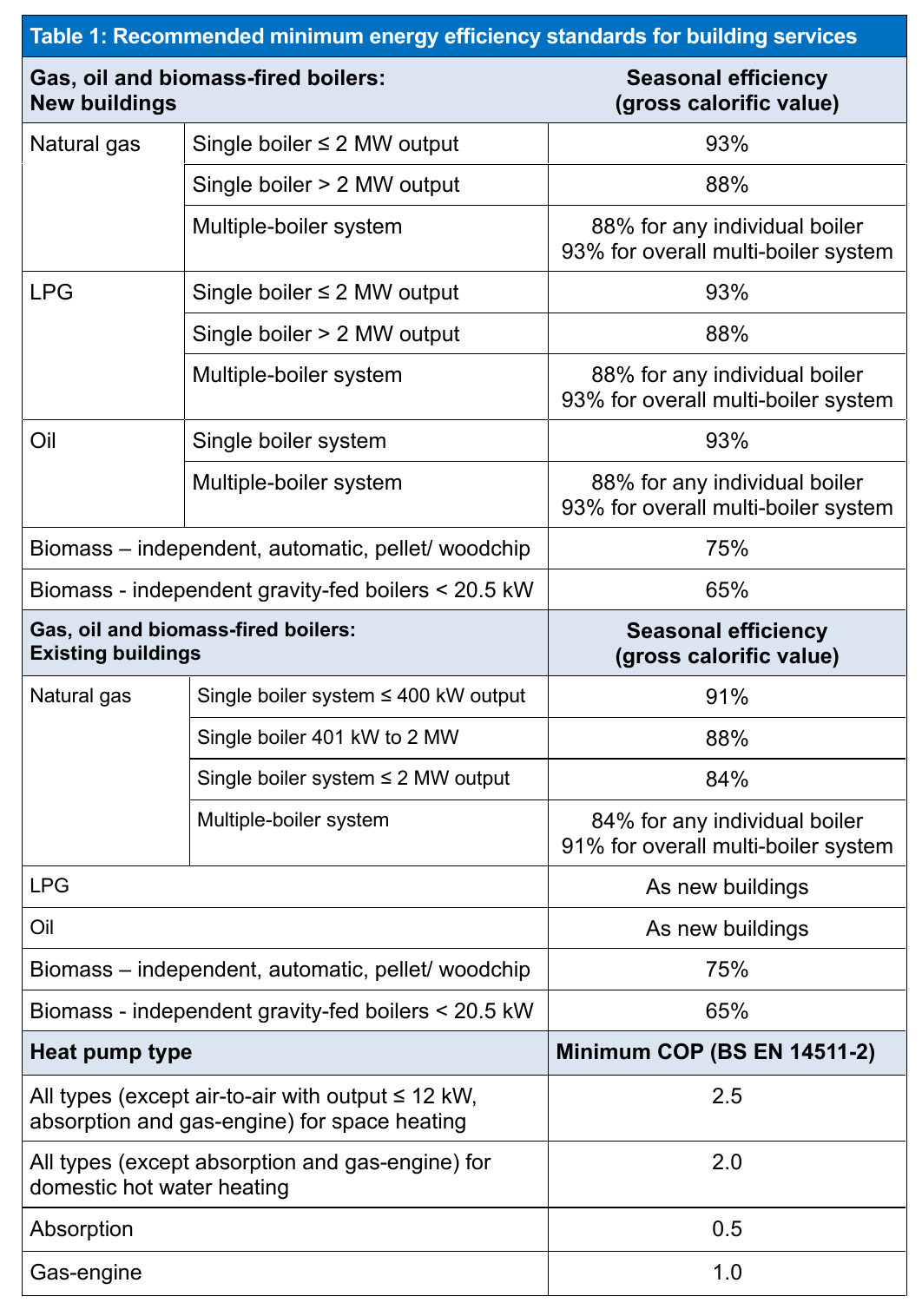
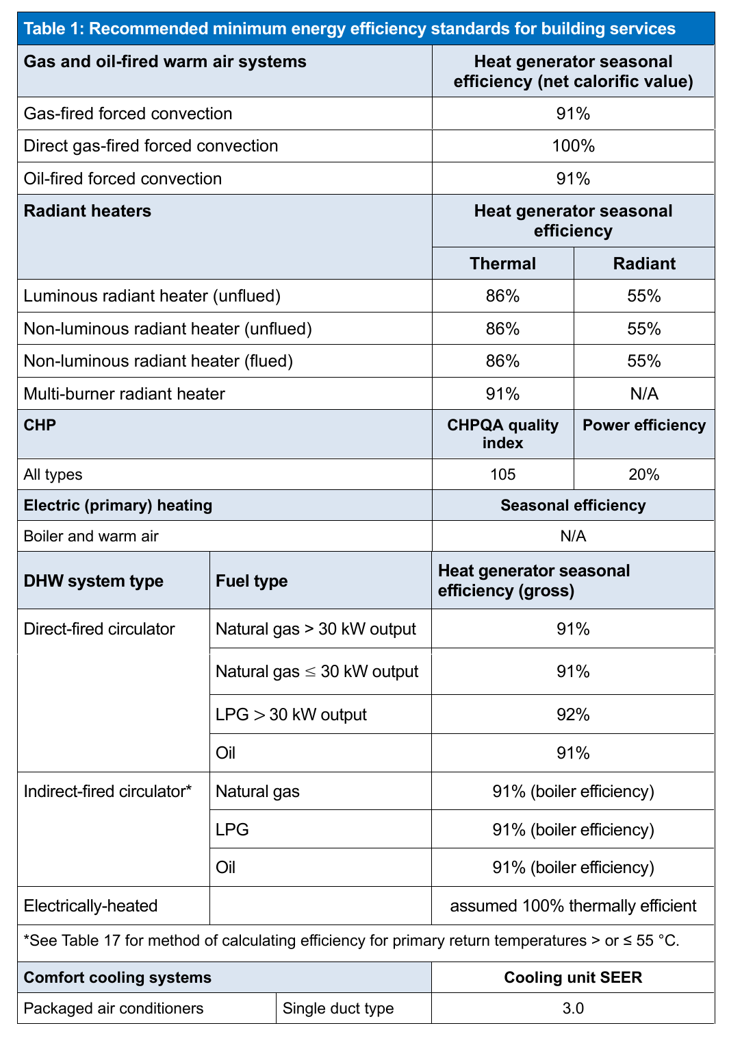
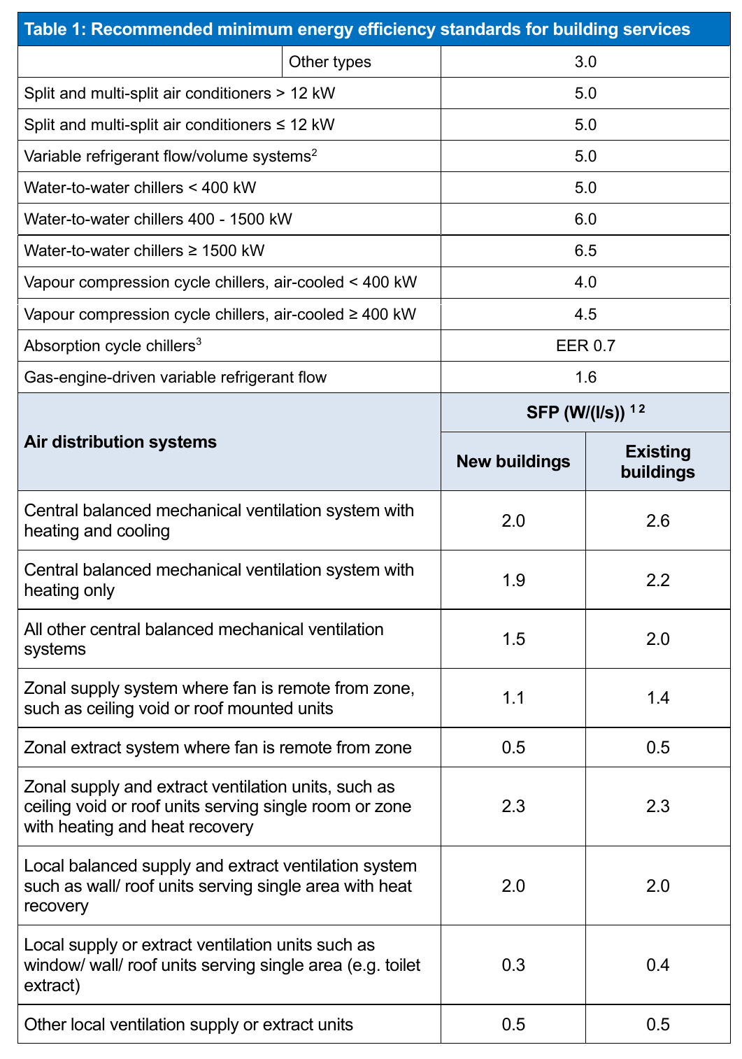
A summary of recommended minimum energy efficiency standards is presented in Table 1 at the end of this section.
1.2 Innovative systems
It is also important to note that this guide covers a range of frequently occurring situations. It deals with the most commonly used fixed building services technologies. In doing so it neither endorses these methods and technologies nor excludes other more innovative technologies that may offer an alternative means of meeting the functional requirements of the building regulations.
Where the alternative technology has been the subject of a recognised testing procedure that assesses its energy performance, this may be used to indicate that the system is adequately efficient. In the event that there is no recognised testing standard, suitable
1.3 Implemented European Directives
#Source page 7
calculations or modelling methods should be used to show the carbon performance of the system.
1.3 Implemented European Directives
The design and installation of fixed building services products, such as boilers, circulators and heat pumps, shall at the appropriate time comply with all relevant requirements of EU Directives to December 2020, as currently implemented via UK legislation. See also Regulations: ecodesign of energy-consuming products - GOV.UK (www.gov.uk)
National building regulations continue to implement elements of The Energy Performance of Buildings Directive 2010/31/EU and its most recent 2018 amendment (for example by setting standards for new buildings and new building work).
For guidance on the most recent changes affecting new and existing non domestic buildings, see Section 6 Energy of the 2022 Non-Domestic Technical Handbook.
For guidance on other requirements relating to building certification and inspection of heating and air conditioning systems, see the BSD website3.
1.4 Status of guide
The building regulations in Scotland are expressed in terms of functional standards. These standards are statements of functions the complete building must fulfil or allow. The standards are set out in building regulations and are intended to:
•secure the health, safety and welfare and convenience of persons in or about buildings;
•further the conservation of fuel and power; and
•further the achievement of sustainable development.
These functional requirements are often drafted in broad terms and so, from the standard alone, it may not always be immediately clear to a person carrying out work how to comply with the relevant requirements. Consequently, the Building Standards Division issues guidance in the form of Technical Handbooks and other published information, such as this document, which provide practical guidance on ways of complying with specific aspects of the building regulations in most common building situations.
The Technical Handbooks are intended to provide practical guidance, but they are not intended to be comprehensive. Consequently, they may contain references to other documents which will provide more detailed information and assistance on parts of the guidance. This guide is one of those documents. It provides more detailed information on the guidance contained in Section 6 Energy of the Non-domestic Technical Handbook about compliance with the energy efficiency requirements which apply when installing fixed building services in new and existing buildings.
If you follow the guidance in the Technical Handbooks and companion documents, such guidance may be relied on in any proceedings as tending to negative liability for an alleged
1.5 How to use the guide
#Source page 8
contravention of the building regulations (refer to Section 0 of the Technical Handbooks for further explanation).
However, in each every case it is for the verifier (local authority) to determine whether work complies with the requirements of the building regulations. Where there is doubt, it is appropriate to check with the verifier before starting work to establish what is necessary for compliance with building regulations. In Scotland, all new buildings and much work to existing buildings will require the issue of a building warrant prior to any works commencing on site. Information on works which must comply with building regulations but for which a building warrant is not required are set out in schedule 3 to regulation 5 (refer to Section 0 of the Technical Handbooks).
1.5 How to use the guide
The guide is divided into the following sections:
Section 1: Introduction and summary of energy efficiency standards
Section 2: Gas, oil and biomass-fired boilers
Section 3: Heat pumps
Section 4: Gas and oil-fired warm air heaters
Section 5: Gas and oil-fired radiant heaters
Section 6: Combined heat and power
Section 7: Direct electric space heating
Section 8: Domestic hot water
Section 9: Comfort cooling
Section 10: Air distribution
Section 11: Pipework and ductwork insulation
Section 12: Interior lighting
Section 13: Heating and cooling system circulators and water pumps
Section 14 – Building Automation and Control Systems
Section 15 – Self-Regulating Devices
Section 16: On-site generation of electricity
Supplementary information is shown in blue italics or as text in light blue tables. This may be further information to help in establishing the minimum energy efficiency provisions needed to comply with the building regulations or it may be guidance on best practice that goes beyond the recommended minimum standards.
Key terms are printed in italics and are defined at appropriate points throughout the guide.
Referenced British and European Standards are note by their designation number. They are presented with their full title and current version (at date of publication), alongside other cited sources of further guidance, in Appendix B. For the purpose of meeting building regulations, a more recent edition of a published standard may be referred to and applied unless there is guidance to the contrary within this document.
1.6 Key terms for space heating and domestic hot water systems
#Source page 9
The following general definitions are applicable to the sections that deal with space heating and hot water. Further definitions are included in later sections as appropriate.
Heat generator means a device for converting fuel or electricity into heat – e.g. a boiler or radiant heater.
Heat generator efficiency means the useful heat output divided by the energy input in the fuel (based on gross calorific value) or electricity delivered to the heat generator, as determined by the appropriate test methods for that type of heat generator.
Heat generator seasonal efficiency means the estimated seasonal heat output from the heat generator divided by the heat input. This will depend on the heat generator efficiency and the operating mode of the heat generator over the heating season. For example, in the case of boilers it is a ‘weighted’ average of the efficiencies of the boiler at 30% and 100% of the boiler output. For other technologies the heat generator seasonal efficiency may be the same as the heat generator efficiency.
Minimum controls package means a package of controls specific to each technology that represents the recommended minimum provision necessary to meet the building regulations energy efficiency requirements.
Additional measures means additional controls or other measures that go beyond the recommended minimum controls package.
Space heating system means the complete system that is installed to provide heating to the space. It includes the heating plant and the distribution system by which heating is delivered to zones.
Domestic hot water system means a local or central system for providing hot water for use by building occupants.
1.7 Work on existing systems
A requirement of building regulations is that work on existing buildings should be carried out in such a way that when the work is complete:
a.the work itself complies with the applicable requirements of building regulations
b.the parts of the building not affected by the work are no worse in relation to the requirements of regulations than before the work was started.
This means that when a system component like a boiler or a room thermostat is replaced, only the new component is expected to comply with the provisions in this guide (which in some cases may be lower than for new systems).
When replacing a boiler, the boiler controls are considered to be part of the boiler installation and should therefore meet the standards set out in the relevant sections of this document.
It is not a general requirement to upgrade the rest of an existing heating system, but this guide does identify conditions for upgrade of wet heating systems under section 1.9 and also include some recommendations on minor upgrades for compliance with building regulations where they would be cost-effective and may be necessary to ensure efficient or optimal operation of the new component.
1.8 Replacement of primary heating appliances
#Source page 10
When replacing an existing appliance, the seasonal efficiency of the new equipment should be as stated in the relevant fuel-based section of this guide, subject to any guidance identifying alternatives in exceptional circumstances.
If the replacement involves a change in fuels then the system should both:
a.not produce more CO 2 emissions per kWh of heat than the appliance being replaced
b.not use more energy, per kWh of heat generated, than the appliance being replaced.
For example:
Replacing a 70% efficient LPG boiler with emissions of 0.241 kg.CO2/kWh with a 90% efficient oil-fired boiler with emissions of 0.298 kgCO 2/kWh.
CO 2 emissions –
•LPG boiler: 0.241/0.70 = 0.34 kgCO 2/kWh
•Oil boiler: 0.298/0.90 = 0.33 kgCO 2/kWh
Delivered energy –
•LPG boiler: 1.0/0.70 = 1.43 kWh/kWh
•Oil boiler: 1.0/0.90 = 1.11 kWh/kWh
In this instance, the oil boiler has both lower CO 2 emissions and energy demand than the LPG boiler being replaced, and therefore complies.
1.9 Sizing heating and hot water system
The specification of space heating systems should be based on an appropriate heat loss calculation for the building, based on BS EN 12831-1 and CIBSE Guide B1. Systems should not be significantly oversized.
Where a wet heating system is being newly installed, or where replacement in an existing building includes both the heating appliance and the majority of the emitters (e.g. emitters providing more than 50% of the calculated heat demand), the system should be configured and sized to allow the space heating system to operate effectively, and in a manner which meets the heating needs of the building, based upon a mean water temperature of 50 °C or lower and a flow/return ΔT of 10 ºC or lower.
Where it is not feasible to install a space heating system which can operate at this temperature (for example, where there is insufficient space for larger radiators, or the existing distribution system is provided by higher temperature heat from a low carbon external heat network) the space heating system should be designed to the lowest design temperature possible which will still meet the heating needs of the building.
1.10 Summary of recommended minimum energy efficiency standards
Unless specified otherwise in this guide, it is recommended that, where relevant, building services are provided with controls that as a minimum correspond to Band C in BS EN 15232:2017 – ‘Energy performance of buildings – impact of building automation, controls and building management’.
Page 11
#Source page 11
Table 1: Recommended minimum energy efficiency standards for building services
Page 12
#Source page 12
Table 1: Recommended minimum energy efficiency standards for building services
Page 13
#Source page 13
Table 1: Recommended minimum energy efficiency standards for building services
Page 14
#Source page 14
| Table 1: Recommended minimum energy efficiency standards for building services | ||
| Fan assisted terminal Variable Air Volume | 0.5 | 0.5 |
| Fan coil unit (rating weighted average) 3 4 | 0.3 | 0.3 |
| Kitchen extract, fan remote from zone with grease filter | 1.0 | 1.0 |
| Heat exchanger type | Dry heat recovery efficiency | |
| Plate heat exchanger | 50% | |
| Heat pipes | 60% | |
| Thermal wheel | 65% | |
| Run around coil | 45% | |
| Internal lighting | Effective lighting efficacy | |
| General lighting (minimum efficacy) | 95 luminaire lumens per circuit-watt | |
| Display lighting (minimum efficacy) | 22 lamp lumens per circuit-watt | |
| Lighting system (LENI calculation) | ≤ lighting energy limit (kWh/m²/year) specified in Table 28 | |
| Building Automation and Control Systems | Minimum provision | |
| Installed systems | BS EN 15232 Class A Rated type system |
Section 2: Gas, oil and biomass-fired boilers
#Source page 15
2.1 Introduction
This section provides guidance on specifying gas, oil and biomass-fired space heating systems for new and existing buildings to meet relevant energy efficiency requirements in building regulations.
The guidance applies to wet central heating systems using commercial boilers fired by:
•natural gas
•liquid petroleum gas (LPG)
•oil, and
•biomass.
The guidance in this section does not cover:
•steam boilers (as these are used primarily for processes rather than provision of space heating), or
•electric boilers (for which see Section 7).
2.2 Key terms
The terminology used to describe efficiencies for boiler systems is detailed below. In this section the heat generator is a boiler.
Biomass means all material of biological origin, excluding material embedded in geological formations and transformed to fossil fuel.
Boiler efficiency means the energy delivered by the water as it leaves the boiler (or boilers in multi-boiler installations) to supply the heat emitters, divided by the energy (based on gross calorific value) in the fuel delivered to the boiler, expressed as a percentage. It is an expression of the boiler’s performance and excludes energy used by boiler auxiliary controls, pumps, boiler room ventilation fans, mechanical flue extraction fans and fan dilution systems.
Effective boiler seasonal efficiency is the boiler seasonal efficiency (as calculated by Equation 2 below for individual boilers, or by Equation 3.1 for multiple boilers).
Economiser means a device, including a secondary heat exchanger fitted on or near to a boiler, which provides additional heat transfer capacity. For the purposes of this guide, any boiler which will be supplied with an economiser should have the economiser fitted when the boiler efficiency is tested according to the standards that are used to demonstrate compliance with the Boiler Efficiency Directive. The effect of this on the boiler efficiency at 30% and 100% of the boiler output may be taken into account in the values used for the calculation of the boiler seasonal efficiency using Equations 2 or 3.1 or the three-step method and Equations 3.2 and 3.3, as appropriate.
Condensing boiler means a boiler that offers a higher energy efficiency by recovering heat from the flue gases. This is achieved by increasing the heat exchanger surface area, which recovers extra sensible heat whenever the boiler fires. The boiler becomes even more efficient when system water temperatures are low because the larger heat exchanger area
Page 16
#Source page 16
promotes condensation, allowing much of the latent heat to be recaptured. Standing losses (when the boiler is not firing) are low and part load performance is very good. In multiple- boiler systems, condensing boilers can be used as the lead boiler.
Standard boiler means, in the context of this document, a non-condensing boiler.
Zone control means independent control of rooms or areas within buildings that need to be heated to different temperatures at different times. Where several rooms or areas of a building behave in a similar manner, they can be grouped together as a ‘zone’ and put on the same circuit and controller.
Sequence control enables two or more heating boilers to be switched on or off in sequence when the heating load changes. This maximises the efficiency of the boilers, so reducing fuel consumption, and reduces wear and tear on the boilers.
Direct acting weather compensation is a type of control that enables a heat generator to work at its optimum efficiency. The control allows the boiler to vary its operating flow temperature to suit the external temperature conditions and the temperatures inside the building. Weather compensation relies on communication between an external sensor and one inside the boiler. The boiler’s water flow temperature is varied accordingly, so that energy is not wasted by the boiler turning on and off.
Weather compensation via a mixing valve is similar to direct acting weather compensation except that the outside temperature is used to control the temperature of water supplied to the heat emitters by mixing the boiler flow and return rather than by altering the boiler temperature.
Optimum start is a control system or algorithm which starts plant operation at the latest time possible to achieve specified conditions at the start of the occupancy period.
Optimiser is a control system employing an optimum start algorithm.
Optimum stop is a control system or algorithm which stops plant operation at the earliest possible time such that internal conditions will not deteriorate beyond pre-set limits by the end of the occupancy period.
Two-stage burner control is a type of control that offers two distinct boiler firing rates.
Multi-stage burner control is a type of control that offers more than two distinct firing rates, but without continuous adjustment between firing rates.
Modulating burner control is a type of control that provides a continuously variable firing rate, which is altered to match the boiler load over the whole turndown ratio.
Decentralisation means the replacement of centralised boiler plant and its associated distribution pipework with several smaller, more accurately sized boiler plants, installed within or adjacent to the buildings or systems they serve. This eliminates long pipe runs between buildings or through unheated areas, so reducing heat losses.
Building management system (BMS) means a building wide network which allows communication with and control of items of HVAC plant (and other building systems) from a single control centre, which may be local or remote. More advanced (‘full’) building management systems offer a wide range of functions, including sequential control, zone control, weather compensation, frost protection and night set-back, as well as monitoring and targeting. See also section 14 on Building Automation and Control Systems.
2.3 Determining boiler seasonal efficiency
#Source page 17
Single-boiler systems and multiple-boiler systems with identical boilers
For boilers the relevant heat generator seasonal efficiency is the boiler seasonal efficiency. The boiler seasonal efficiency is a ‘weighted’ average of the efficiencies of the boiler at 15%, 30% and 100% of the boiler output (the efficiency at 15% being taken to be the same as that at 30%). This is usually quoted by the boiler manufacturer. Note that the efficiencies based on net calorific value should be converted to efficiencies based on gross calorific value using the appropriate conversion factor in SAP 10 Table E4.
The boiler efficiencies, measured at 100% load and at 30% load, are used in Equation 2 to calculate the boiler seasonal efficiency. The weighting factors in Equation 2 reflect typical seasonal operating conditions for a boiler.
Boiler seasonal efficiency = 0.81η30% + 0.19 η100% Equation 24
where:
η30% is the gross boiler efficiency measured at 30% load η100% is the gross boiler efficiency measured at 100% load
Equation 2 applies to:
•single-boiler systems where the boiler output is ≤ 400 kW and the boiler will operate on a low temperature system
•multiple-boiler systems where all individual boilers have identical efficiencies and where the output of each boiler is ≤ 400 kW operating on low temperature systems.
For boilers with an output > 400 kW, the manufacturer’s declared efficiencies should be used.
Multiple-boiler systems with non-identical boilers replacing existing systems
Where more than one boiler is installed on the same heating system and the efficiencies of the boilers are not all identical, Equation 3.1 should be used to calculate the overall boiler seasonal efficiency. All boilers should be included in the calculation, even when some are identical. The boiler seasonal efficiency for multiple-boiler systems with non-identical boilers is:
ηOSBE = Σ(η BSE x R) Equation 3.1
ΣR where:
ηOSBE is the gross overall boiler seasonal efficiency, being an average weighted by boiler output of the individual seasonal boiler efficiencies ηBSE is the gross boiler seasonal efficiency of each individual boiler calculated using Equation 2
R is the rated output in kW of each individual boiler (at 80/60°C).
Page 18
#Source page 18
Multiple-boiler systems in new buildings
In the case of multiple boilers in new buildings, the more accurate three-step method described below should be used to calculate the overall seasonal boiler efficiency. These steps can readily be programmed into a spreadsheet to automate the calculation.
Step 1 - Determine the load on each boiler for each of the three system part-load conditions of 15%, 30% and 100%. For example, if the total system output is made up of three equally sized boilers, at 15% of system output the lead boiler will be operating at 45% of its rated output, with the other two boilers switched off.
Step 2 - Determine the efficiency of each boiler for the above operating conditions. In the above example, the efficiency of the boiler operating at 45% can be determined by linear interpolation between its efficiencies at 30% and 100% of rated output. Where it is necessary to determine the efficiency of an individual boiler at 15% of rated output, this should be taken as the same as the efficiency at 30% of rated output. (Note that the efficiency at 15% of rated output will only be needed if a single boiler meets the full design output)
Step 3 - Calculate the overall operating efficiency at each of the system part load conditions using:
ηp = Q p / Σ(q b.p/ηb,p) Equation 3.2 where:
ηp is the system efficiency at part load condition p, i.e. 15%, 30% and 100% of system rated output
Q p is the system heat output at part load condition p q b,p is the individual boiler heat output at system part load condition p ηb,p is the individual boiler efficiency at system part load condition p.
Step 4 - Calculate the overall boiler seasonal efficiency as the weighted average of the efficiencies at the three load conditions using:
ηOSBE = 0.36η15% + 0.45η30% + 0.19η100% Equation 3.3
Table 2 is a worksheet for following through these calculations (using manufacturer data for boiler efficiency at 100% and 30% output). Table 3 shows a completed example calculation using this worksheet, for the case where a system with a rated output of 625 kW is served by three boilers, each rated at 250 kW. The first two boilers are condensing boilers, while the third is a standard boiler. Because the installation is oversized (750 kW compared to 625 kW), at full system output the final boiler is only operating at 50% output (125/250).
The notes at the foot of the table illustrate how the various values are calculated.
Page 19
#Source page 19
Table 2: Worksheet for calculating the overall boiler seasonal efficiency of a multiple-boiler system using the alternative three-step method
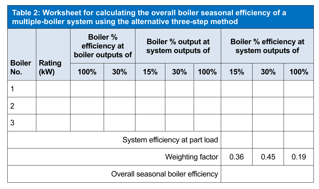
Table 3: Example calculation of the overall boiler seasonal efficiency of a multiple-boiler system in a new building
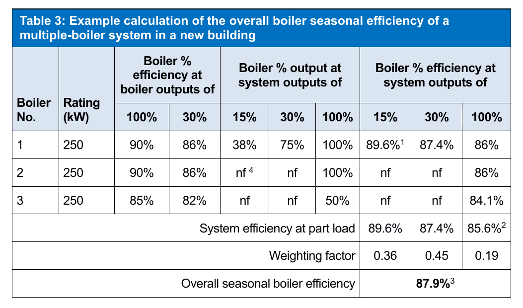
Notes:
1.Calculated by linear interpolation: ηb,p = η30% – (η30% – η100% ) x
(qb,p – 30%)
(100% – 30%)
(38% – 30%)
(100% – 30%) η1,15% = η30% – (η30% – η100% ) x
2.Calculated by dividing the thermal output of the system (625 kW) by the rate of fuel consumption, which is given by
2.4 Boilers in new buildings
#Source page 20
625
250x 100% + 250 x 100% + 250 x 50%
86.0% 86.0% 84.1%
•the sum of the boiler outputs divided by their individual operating efficiency, i.e
3.Calculated as the weighted average, i.e.
(89.6% x 0.36) + (87.4% x 0.45) + (85.6% x 0.19) = 87.9%
4.nf = not firing
2.4 Boilers in new buildings
Background
New buildings should be provided with high efficiency condensing or non-condensing boilers that meet the recommended minimum standards for heat generator seasonal efficiency in this guide.
Commercial heating systems are inherently more complicated than domestic systems with a wider range of temperatures and heat emitters. The selection of condensing or non- condensing boilers will be determined by application and physical constraints.
Note: Water quality can have a major impact on system efficiency. It is important that designers take appropriate measures to ensure that the system water is of good quality.
Condensing boilers will meet projected efficiencies only when they operate with a system return temperature between 30 °C and 40 °C for 80% of the annual operating hours. With a return temperature of 55 °C and above, condensing boilers will not produce condensate and will have similar efficiencies to non-condensing high efficiency boilers. Some systems are suitable for weather compensation, which allows return temperatures to fall into the condensing range for some periods of the heating season, and they may be best served by a mixture of condensing and non-condensing boilers.
The efficiency value that should be entered into approved NCM tools to calculate the emissions and delivered energy rates is the heat generator seasonal efficiency.
Recommended minimum standards
To meet relevant energy efficiency requirements in the building regulations when installing boiler plant in new buildings:
a.where a single boiler is used to meet the heat demand, its boiler seasonal efficiency (gross calorific value) calculated using Equation 2 should be not less than the value in Table 4
b.for multiple-boiler systems, the boiler seasonal efficiency of each boiler should be not less than 82% (gross calorific value), as calculated using Equation 2; and the overall boiler seasonal efficiency of the multiple-boiler system, as defined by the three-step method and calculated using Equations 3.2 and 3.3, should be not less than the value in Table 4
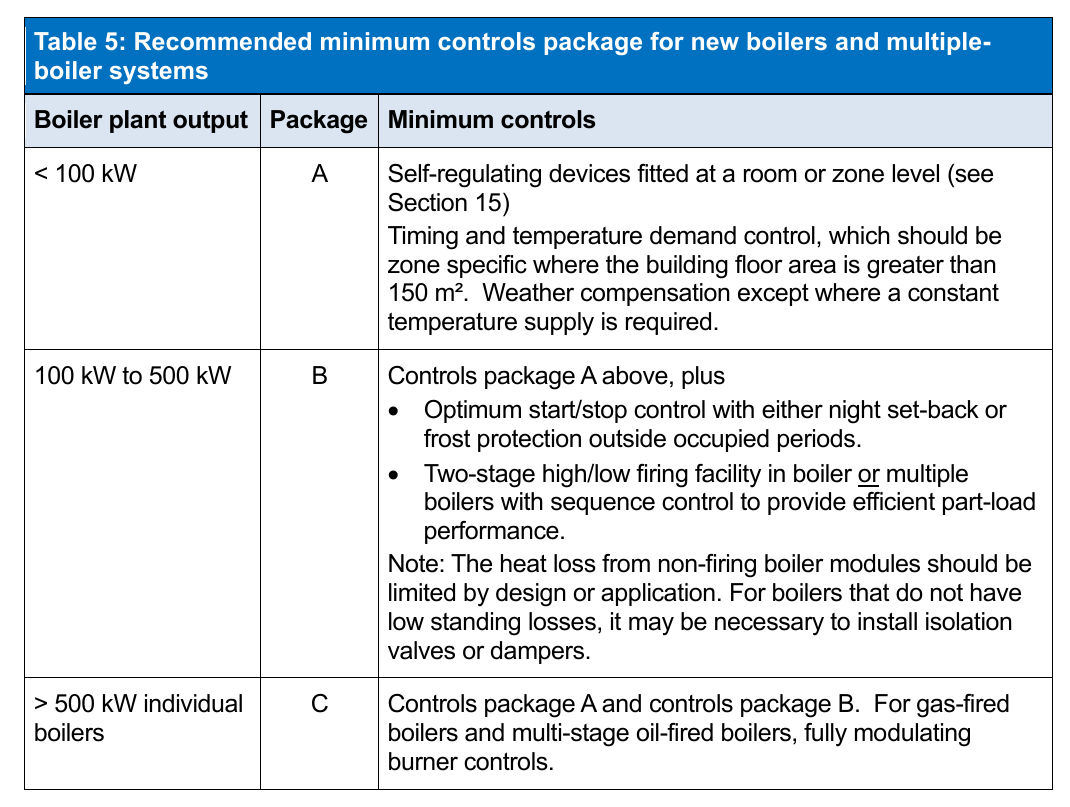
c.the relevant minimum controls package in Table 5 should be adopted.
Page 21
#Source page 21
Table 4: Recommended minimum heat generator seasonal efficiency for boiler systems in new buildings
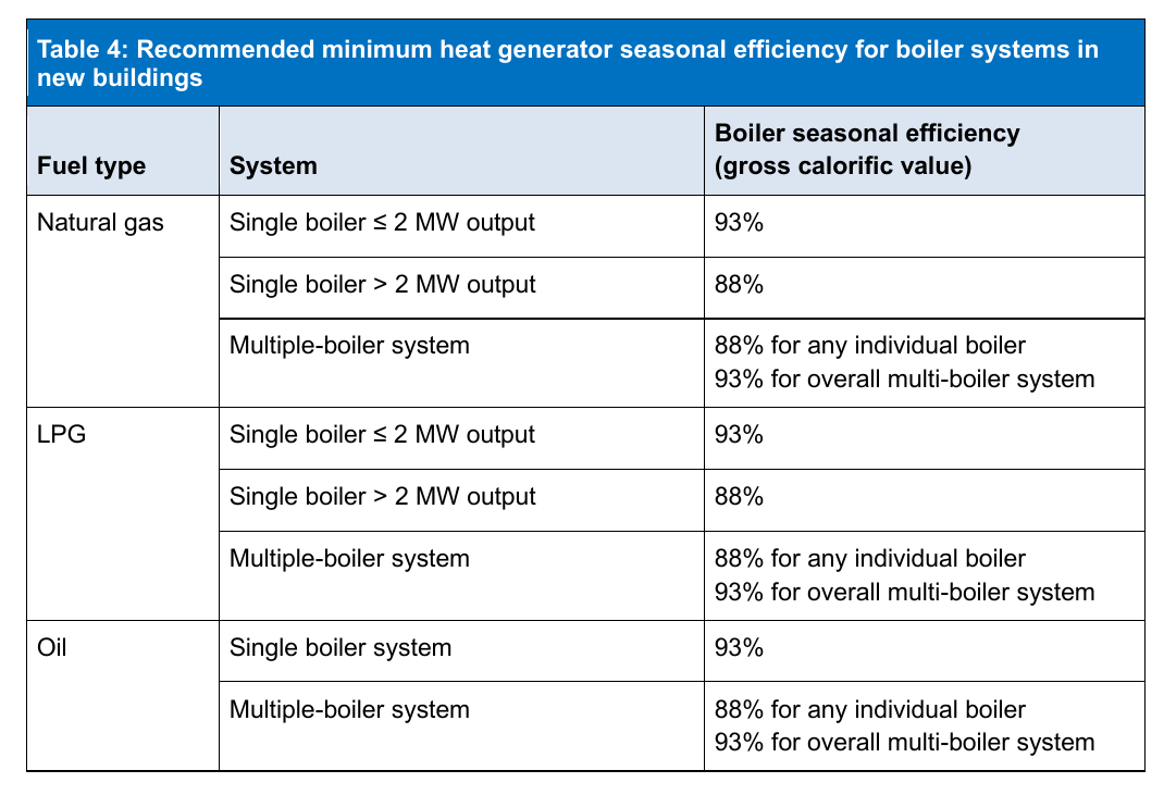
Table 5: Recommended minimum controls package for new boilers and multiple-boiler systems
2.5 Boilers in existing buildings
#Source page 22
Background
Boiler efficiencies have improved markedly over recent years. A modern boiler meeting the minimum requirements of the Boiler Efficiency Directive has a boiler seasonal efficiency of approximately 78.5% (based on gross calorific value). This guidance recognises that in many cases using condensing boiler technology in existing buildings would be either technically impractical (due to flueing constraints) or economically unviable. For this reason non-condensing boilers may be used provided that they meet the recommended minimum efficiency standards given in this section.
To meet relevant energy efficiency requirements in the building regulations when installing boiler plant in existing buildings:
a.the boiler seasonal efficiency of each boiler (in a single-boiler system or a multiple- boiler system with identical boilers) calculated using Equation 2 should be not less than the value in Table 6
b.for multiple-boiler systems using non-identical boilers, the overall boiler seasonal efficiency calculated using Equation 3.1 should be not less than the value in Table 6
c.the controls package in Table 7 should be adopted – i.e. zone control, demand control and time control
| Table 6: Recommended minimum boiler seasonal efficiency for boiler systems in existing buildings | ||
| Gas, LPG and oil-fired boilers | Seasonal efficiency (gross calorific value) | |
| Natural gas | Single boiler system ≤ 400 kW output | 91% |
| Single boiler 401 kW to 2 MW | 88% | |
| Single boiler system ≤ 2 MW output | 84% | |
| Multiple-boiler system | 84% for any individual boiler 91% for overall multi-boiler system | |
| LPG | As new buildings | |
| Oil | As new buildings |
2.6 Biomass boilers
#Source page 23
| Table 7: Recommended minimum controls package for replacement boilers in existing buildings | |
| Minimum controls package | Suitable controls |
| a. Room/Zone control | Self-regulating devices fitted at a room or zone level as far as is practicable (see Section 15) |
| b. Demand control | Room thermostat which controls through a diverter valve with constant boiler flow water temperature. This method of control is not suitable for condensing boilers. |
| c. Time control | Independent time controls. |
2.6 Biomass boilers
Background
The method in Section 2.4 for calculating the seasonal efficiency of single and multiple boilers fired by gas, LPG and oil is not appropriate for biomass boilers. For biomass boilers, requirements and test methods are covered by BS EN 12809.
Recommended minimum standards
To meet relevant energy efficiency requirements in the Building Regulations:
a.the efficiency of biomass boilers at their nominal load should be at least:
i. 65% for independent gravity-fed boilers < 20.5 kW ii. 75% for independent automatic pellet/ woodchip boilers
b.controls as for gas, LPG and oil boilers in Table 5 should be provided, where technically feasible.
Section 3: Heat pumps
#Source page 24
3.1 Introduction
This section gives guidance on specifying heat pumps to provide space heating and domestic hot water in new and existing buildings to meet relevant energy efficiency requirements in the Building Regulations. The heat pumps covered in this section take heat energy from a low temperature source and upgrade it to a higher temperature at which it can be usefully employed for heating.
For reverse cycle heat pumps that also provide cooling, see Section 9 of this guide.
3.2 Key terms
Coefficient of performance (COP) is a measure of the efficiency of a heat pump at specified source and sink temperatures, measured using the procedures in BS EN 14511-2:
Heating COP = heat output / power input Equation 4
% COP (COP x 100) is the heat generator efficiency.
Seasonal coefficient of performance (SCOP) is the overall coefficient of performance of the unit for the designated heating season. It makes general assumptions about the amount of auxiliary heating needed to top up the space and water heating available from the heat pump. SCOP is measured in accordance with the procedures in BS EN 14825. The National Calculation Methodology calculates carbon dioxide emission rates from buildings uses SCOP.
3.3 Heat pumps in new and existing buildings
Heat pumps in new and existing buildings should:
a.have a COP which is not less than the value in Table 10; or
b.if air-to-air heat pumps with an output less than or equal to 12 kW, have at least a SCOP ‘D’ rating for the median temperature range in BS EN 14825; and
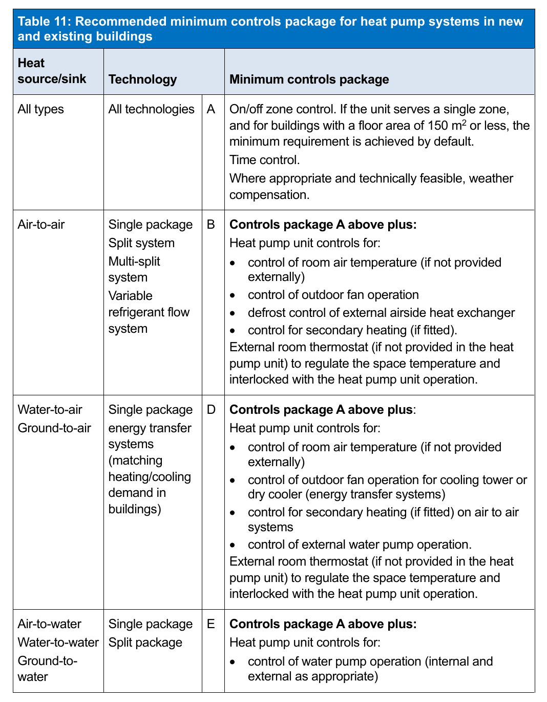
c.feature as a minimum the controls package in Table 11.
| Table 10: Minimum COP for heat pumps in new and existing buildings | |
| Heat pump type | Minimum COP (at rating conditions in BS EN 14511-2) |
| All types (except air-to-air with output ≤ 12 kW, absorption and gas-engine) for space heating | 2.5 |
| All types (except absorption and gas-engine) for domestic hot water heating | 2.0 |
| Absorption | 0.5 |
| Gas-engine | 1.0 |
Note: It is recommended that heat pumps below should be designed and installed in accordance with the technical standards given in the Microgeneration Certification Scheme’s Microgeneration Installation Standard: MIS 3005, subject to the limitations on scope as outlined in this Standard.
Page 25
#Source page 25
For non-residential buildings, the heat pump system can be sized to meet either the full heating and hot water demand or part of it. Economically viable installations provide at least 50% of the heating and hot water demand for the building.
Table 11: Recommended minimum controls package for heat pump systems in new and existing buildings
3.6 Supplementary information
#Source page 26
| Table 11: Recommended minimum controls package for heat pump systems in new and existing buildings | |||
| • control of water temperature for the distribution system • control of outdoor fan operation for air to water units • defrost control of external airside heat exchanger for air to water systems. External room thermostat (if not provided in the heat pump unit) to regulate the space temperature and interlocked with the heat pump unit operation. | |||
| Gas-engine- driven heat pumps are currently available only as variable refrigerant flow warm air systems | Multi-split Variable refrigerant flow | F | Controls package A above plus: Heat pump unit controls for: • control of room air temperature (if not provided externally) • control of outdoor fan operation • defrost control of external airside heat exchanger • control for secondary heating (if fitted). External room thermostat (if not provided in the heat pump unit) to regulate the space temperature and interlocked with the heat pump unit operation. |
In addition to the general guidance for zoning and controls in Section 5, any outdoor fans, including those in cooling towers or dry coolers, should be controlled.
3.6 Supplementary information
| Heat source/sink | Technology | Comments |
| Air-to-air | • Single package | Units may be ducted on one or other of the supply and return air sides or ducted on both sides. Ducting needs to be designed to take into account the maximum specific fan power allowable (see Section 10 of this guide) and to maintain the minimum allowable coefficient of performance. |
| • Split • Multi-split • Variable refrigerant flow • Gas engine- driven | A split system will comprise a single outdoor unit and a single indoor unit as a package. Multi-split and VRF systems will comprise a single outdoor unit and two or more indoor units as a package. Several packages may be used to satisfy the requirements of the building. In order for efficiencies to be maintained, all connecting pipework should be installed in accordance with manufacturers’ recommendations (diameter, length, insulation and riser height). Any ducting should be designed to take into account the maximum specific fan power allowable and to maintain the minimum allowable coefficient of performance. |
Page 27
#Source page 27
| Heat source/sink | Technology | Comments |
| Water-to-air Ground-to-air | • Single package • Energy transfer | Energy transfer systems generally consist of multiple water- source heat pumps connected in parallel to a common closed water loop. They are installed to offset the simultaneous heating and cooling demand in a building due to the different loads present on the aspects of the building. Water circulation pumps for the closed loop should be taken into consideration along with the fan power required for the cooling tower or dry cooler or energy for water pumps for the ground loop if this method is utilised for heat injection and rejection. Any ducting should be designed to take into account the maximum specific fan power allowable and to maintain the minimum allowable coefficient of performance. |
| Air-to-water Water-to- ground Water-to-water | • Single package • Split package | Water circulation pumps for the delivery of heated water to the building along with the energy of water pumps used for the heat source (water or ground) should be considered in the calculation. Any ducting should be designed to take into account the maximum specific fan power allowable and to maintain the minimum allowable coefficient of performance. |
| Additional guidance on design criteria for heating systems with integrated heat pumps is given in BS EN 15450:2007 – ‘Heating systems in buildings. Design of heat pump heating systems’. |
Section 4: Gas and oil-fired warm air heaters
#Source page 28
4.1 Introduction
This section gives guidance on specifying gas and oil-fired warm air heaters for space heating in new and existing buildings to meet relevant energy efficiency requirements in the Building Regulations. The guidance also covers indirect gas or oil-fired heat exchangers (as used in large ducted systems for office blocks, etc.) to provide heating and fresh or conditioned air. Warm air central heating systems are not within the scope of this section but are covered in the relevant heat generator section and Section 10 - Air distribution.
4.2 Key terms
Heat generator seasonal efficiency of air heaters, since they operate under the same conditions at all times, is equivalent to their measured steady state thermal efficiency (net calorific value), which can be obtained from the heater manufacturer’s data and converted to efficiency (gross calorific value) using the conversion factors in SAP 10 Table E4.
The calculation of the thermal efficiency (net) should:
•take account of the heater and the exhaust chimney within the building envelope
•exclude fans.
4.3 Warm air heaters in new and existing buildings
Warm air systems in new and existing buildings should have:
a.a heat generator seasonal efficiency which is no worse than in Table 16
b.a controls package featuring, as a minimum, time control, space temperature control, and, where appropriate for buildings with a floor area greater than 150 m2, zone control.
Table 12: Recommended minimum heat generator seasonal efficiency
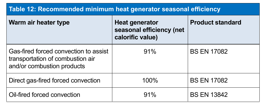
Note: For Direct gas-fired forced convection air heaters, 100% of the net heat input is delivered to the space. Specific ventilation requirements as defined in BS EN 17082 should be met.
Section 5: Gas and oil-fired radiant heaters
#Source page 29
5.1 Introduction
This section gives guidance on specifying radiant heaters for space heating in new and existing buildings to meet relevant energy efficiency requirements in the Building Regulations.
5.2 Key terms
Radiant heater seasonal efficiency (heat generator seasonal efficiency) is equivalent to thermal efficiency (net calorific value).
For flued appliances, the manufacturer of the radiant heater should declare a thermal efficiency measured to the test standards BS EN 117082 or BS EN 13842 as applicable.
The calculation of the thermal efficiency (net calorific value) should:
a.take account of the radiant heater and associated flue pipe/ tailpipe within the building envelope
b.exclude fans.
5.4 Radiant heaters
Radiant heaters in new and existing buildings should have:
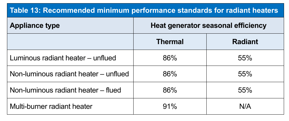
a.an effective heat generator seasonal efficiency not worse than in Table 13
b.a controls package consisting of, as a minimum, time control and space temperature control with black bulb sensors.
Table 13: Recommended minimum performance standards for radiant heaters
Section 6: Combined heat & power
#Source page 30
6.1 Introduction
This section gives guidance on specifying combined heat and power (CHP) systems for space heating, hot water and chilled water (via absorption chillers) in new and existing buildings to meet relevant energy efficiency requirements in the Building Regulations. Guidance on the design of buildings connected to a heat network can be found in Section 7 of the Domestic Building Services Compliance Guide for Scotland.
The guidance in this section covers CHP systems with a total power capacity less than 5 MWe used in commercial applications. The CHP units may or may not supply a heat network.
CHP units are normally used in conjunction with boilers. The majority of the annual heat demand is usually provided by the CHP plant, while the boilers are used to meet peak demand and in periods when the CHP unit is not operating (for example at night or when undergoing maintenance). CHP units may on a relatively small scale supply single buildings, or on a larger scale supply a number of buildings through a heat network. The most common fuel is natural gas, which can be used in spark-ignition gas engines, micro-turbines, or gas turbines in open cycle or combined cycle.
6.3 Key terms
Combined heat and power (CHP) means the simultaneous generation of heat and power in a single process. The power output is usually electricity, but may include mechanical power. Heat outputs can include steam, hot water or hot air for process heating, space heating or absorption cooling.
Combined heat and power quality assurance (CHPQA) is a scheme under which registration and certification of CHP systems is carried out according to defined quality criteria. Further information about the CHPQA programme is available at https://www.gov.uk/guidance/combined-heat-power-quality-assurance-programme.
CHPQA quality index is an indicator of the energy efficiency and environmental performance of a CHP scheme relative to generation of the same amounts of heat and power by alternative means.
Power efficiency is the total annual power output divided by the total annual fuel input of a CHP unit.
6.4 CHP in new and existing buildings
CHP plant in new and existing buildings should have:
•a minimum CHPQA Quality Index (QI) of 105 and power efficiency greater than 20%, both under annual operation
•a control system that, as a minimum, ensures that the CHP unit operates as the lead heat generator
•metering to measure hours run, electricity generated and fuel supplied to the CHP unit.
6.5 Supplementary information
#Source page 31
The CHP plant should be sized to supply not less than 45% of the annual total heating demand (i.e. space heating, domestic hot water heating and process heating) unless there are overriding practical or economic constraints.
6.5 Supplementary information
Heat networks may include other low and zero carbon sources of energy such as heat pumps and heat from waste. Emission factors for EPC reporting should be determined based on the particular details of the scheme, but should take account of the annual average performance of the whole system – that is, of the distribution circuits and all the heat generating plant, including any CHP and any waste heat recovery or heat dumping. The calculation of the carbon dioxide emission rate for the network should be carried out by a suitably qualified person, who should explain how the emission factors were derived.
The design of the heat network connection and the heating control system of the building should take account of the requirements of the network with respect to maintaining low return temperatures at part-load and limiting the maximum flow rate to be supplied by the network to the agreed level. A heat meter should be installed to measure the heat energy supplied and to monitor the maximum heat demand, the maximum heating flow rate and the return temperatures into the heat network.
Section 7: Direct electric space heating
#Source page 32
7.1 Introduction
This section gives guidance on specifying direct electric heaters for space heating in new and existing buildings. It addresses the relevant electric heater types and the minimum provision of controls.
The guidance given in this section covers the following types of electric heating systems, which may be used to provide primary or secondary space heating:
•electric boilers
•electric warm air systems
•electric panel heaters
•electric storage systems, including integrated storage/ direct systems
•electric fan heaters and fan convector heaters
•electric radiant heaters, including quartz and ceramic types.
The guidance does not cover electric heat pumps (see section 3) or portable electric heating devices (outwith the scope of building regulations).
7.2 Electric space heating in new and existing buildings
It is assumed that electric heating devices convert electricity to heat within a building with an efficiency of 100%. A minimum heat generator seasonal efficiency is therefore not specified.
Electric space heating systems in new and existing buildings should meet the minimum standards for:
a.controls for electric boilers in Table 14
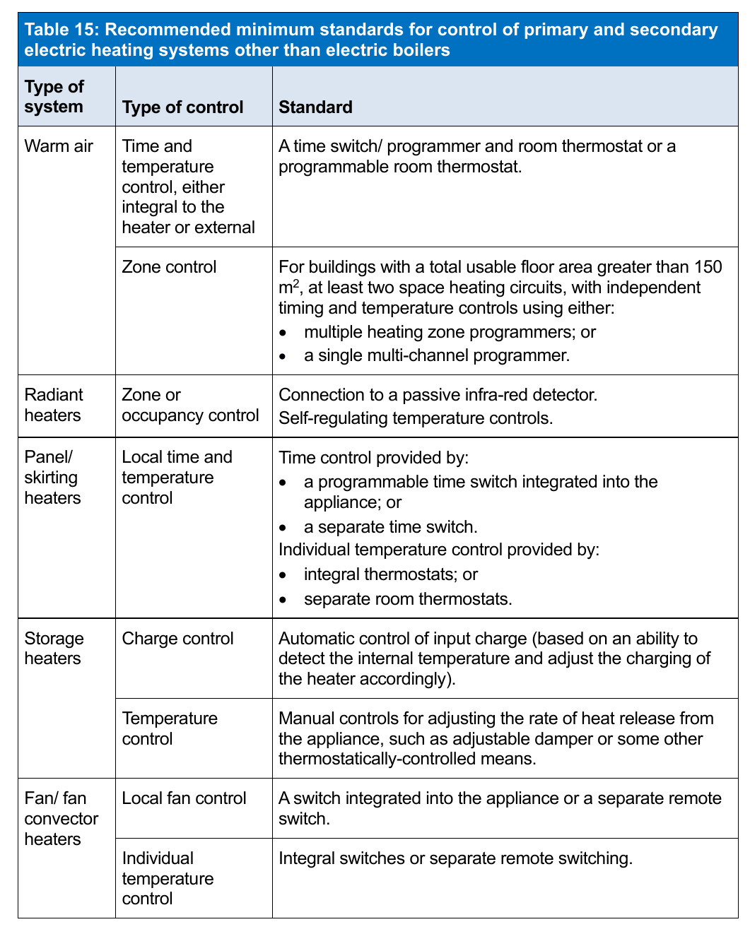
b.controls for electric heating systems other than boilers in Table 15.
| Table 14: Recommended minimum standards for control of electric boiler systems | |
| Type of control | Standard |
| Boiler temperature control | Boiler fitted with a flow temperature control and capable of modulating the power input to the primary water depending on space heating conditions. |
| Zoning | For buildings with a total usable floor area greater than 150 m², at least two space heating zones with independent time and temperature controls using either: • multiple heating zone programmers; or • a single multi-channel programmer. |
Page 33
#Source page 33
| Temperature control of space heating | Separate temperature control of zones within the building using either: • room thermostats or programmable room thermostats in all zones; or • a room thermostat or programmable room thermostat in the main zone and individual radiator controls such as thermostatic radiator valves (TRVs) on all radiators in the other zones; or • a combination of (i) and (ii) above. |
| Time control of space and water heating | Provide using: • a full programmer with separate time control for each circuit; or • separate timers for each circuit; or • programmable room thermostats for the heating circuits, with separate time control for all the circuits. |
Note: An acceptable alternative to the above controls is any boiler management control system that meets the specified zoning, timing and temperature requirements.
Page 34
#Source page 34
Table 15: Recommended minimum standards for control of primary and secondary electric heating systems other than electric boilers
Section 8: Domestic hot water
#Source page 35
8.1 Introduction
This section gives guidance on specifying domestic hot water (DHW) systems for new and existing buildings to meet relevant energy efficiency requirements in the Building Regulations. Domestic hot water systems are referred to as hot water service systems in SBEM.
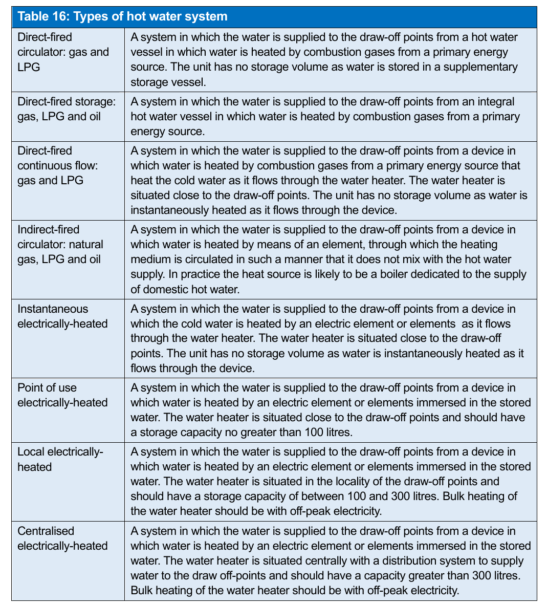
The guidance in this section covers the conventional direct and indirect gas-fired, oil-fired and electrically-heated domestic hot water systems shown in Table 16.
Table 16: Types of hot water system
The recommended minimum standards set out in this section apply only to dedicated water heaters. Central heating boilers which provide space heating and domestic hot water should
8.3 Domestic hot water systems in new and existing buildings
#Source page 36
meet the minimum standards in Section 2; and heat pumps which provide domestic hot water should meet the minim standards in Section 3.
The guidance in this section applies to back-up gas and electric systems used with solar thermal hot water systems, but not to solar thermal systems themselves. For solar systems with a cylinder capacity of less than 440 litres or collector surface area less than 20 m² metres, consult the Domestic Building Services Compliance Guide for Scotland or, for larger systems, the CIBSE Solar heating design and installation guide5.
Note: Water quality can have a major impact on system efficiency. It is important that designers take appropriate measures to ensure that the system water is of good quality.
As well as the building regulations, other regulations apply to the provision of domestic hot water. Energy-saving measures should not compromise the safety of people or the ability of the system to achieve approved regimes for the control of legionella.
8.3 Domestic hot water systems in new and existing buildings
Domestic hot water systems should be sized for the anticipated domestic hot water demand of the building, based on BS EN 12831-3. Systems should not be significantly oversized.
Primary hot water circuits for domestic hot water or heating should have fully pumped circulation where this is compatible with the heat generator.
The thermal efficiency is defined for each system type in Table 17. Thermal efficiency should include the heat generator and any integral storage vessel, but exclude the following, where present.
•Secondary pipework.
•Fans and pumps.
•Diverter valves, solenoids, actuators.
•Supplementary storage vessels.
Domestic hot water systems in new and existing buildings should meet the recommended minimum standards for:
a.heat losses from DHW storage vessels in Table 18, or maintenance consumption values in EN 89.
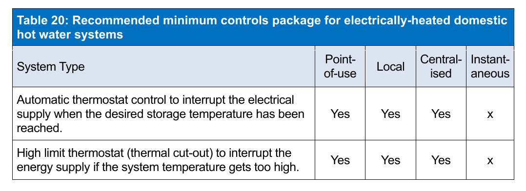
b.controls in Tables 19 and 20.
Page 37
#Source page 37
Table 17: Minimum thermal efficiencies for Domestic Hot Water systems in new and existing buildings
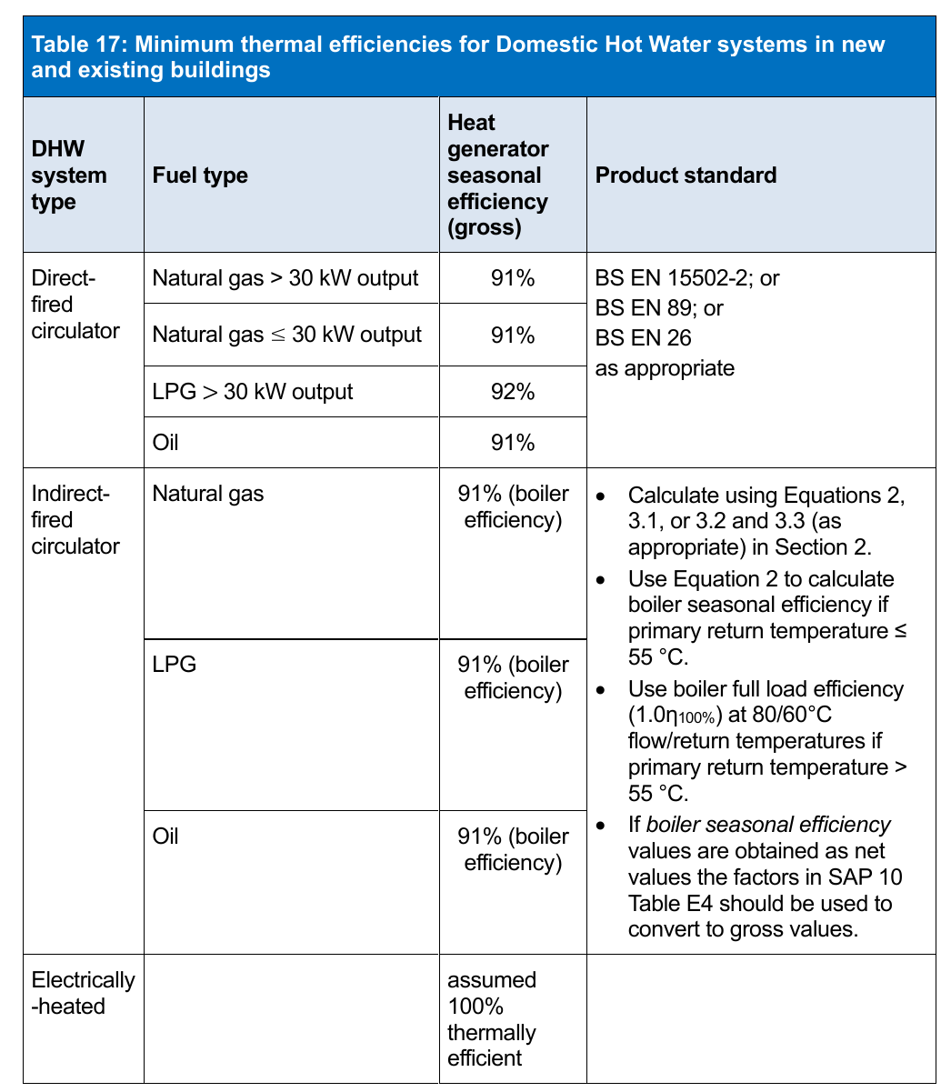
Where efficiency data is not readily available, efficiencies can be calculated using manufacturers’ recovery rates and the following equations:
Gross thermal efficiency = heater output / gross input Equation 8
Heater output = recovery rate of heater in litres/second x Equation 9 x specific heat capacity of water x temperature rise of water
Page 38
#Source page 38
Table 18: Recommended maximum heat losses from DHW storage vessels
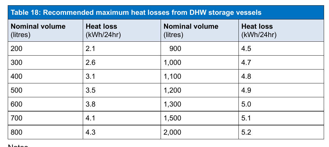
1.For guidance on maximum heat losses from DHW storage vessels with a storage volume less than 200 litres, see BS EN 15450.
2.The heat loss from electrically-heated cylinders (volume V litres) should not exceed 1.28 x (0.2+0.051V 2/3) if point-of-use or 1.28 x (0.051V 2/3) if local.
| Table 19: Recommended minimum controls package for gas and oil-fired domestic hot water systems | |
| System type | Controls package |
| Direct-fired circulator; Direct-fired storage; or Indirect-fired | • Time control independent of space heating circuits. • Electronic temperature control. • Automatic thermostat control to shut off the burner/primary heat supply when the desired temperature of the hot water has been reached. • High limit thermostat to shut off primary flow if system temperature too high. |
| Direct-fired continuous flow | Controls as above, plus: • A flow sensor to control the rate of flow through the heat exchanger. This should control outlet temperatures and, if the sensor detects insufficient flow, shut off the burner/heat input. |
Table 20: Recommended minimum controls package for electrically-heated domestic hot water systems
8.5 Supplementary information on electric water heaters
#Source page 39
| System Type | Point- of-use | Local | Central- ised | Instant- aneous |
| Manual reset in the event of an over-temperature trip. | Yes | Yes | Yes | x |
| 7-day time clock (or BMS interface) to ensure bulk heating of water using off-peak electricity. Facility to boost the temperature using on-peak electricity (ideally by means of an immersion heater fitted to heat the top 30% of the cylinder). | x | Yes | Yes | x |
| High limit thermostat (thermal cut-out) to interrupt the energy supply if the outlet temperature gets too high. (Note: Outlet temperature is controlled by rate of flow through the unit, which on basic units would be by the outlet tap or fitting). | x | x | x | Yes |
| Flow/ pressure sensor that only allows electrical input should sufficient flow through the unit be achieved. | x | x | x | Yes |
8.5 Supplementary information on electric water heaters
Point-of-use
Relevant standard is BS EN 60335-2-21.
Instantaneous
Relevant standard is BS EN 60335-2-35.
Local
For vented systems, relevant standard is BS EN 60335-2-21, for unvented systems, relevant standard is BS EN 12897.
Centralised
Relevant standard is BS 853-1.
Bulk heating of the water should utilise off-peak electricity where possible.
When using off-peak electricity a ‘boost heater’ should be fitted to allow ‘on-peak’ heating. The ‘boost heater’ should heat the top 30% of the cylinder and be rated to approximately 30% of the main off-peak heater battery. The kW load will depend on the recovery time required.
The heater battery should either be of removable core or rod element construction. Removable core construction allows elements to be changed without removing the heater from the vessel or draining the system. For removable core construction, the maximum element watts density should not exceed 3 W/cm2 for copper tubes or 2.5 W/cm2 for stainless steel tubes. For rod element construction, elements should be of nickel alloy 825 sheath, be U-bent and have a maximum watts density of 10 W/cm2. Temperature control should be by means of ‘on/off’ control of the heater battery utilising stage ramping for loadings above 30 kW. Thermostatic control is an ideal solution.
The control sensor should be mounted in the cylinder at an angle of approximately 45° to the heater and at a level just above the heating bundle. The over-temperature sensor
Page 40
#Source page 40
(high limit) should be mounted in the top 30% of the cylinder directly above the heater bundle. A manual reset should be required in the event of an over-temperature trip.
For loadings greater than 6 kW, temperature sensors should not be fitted to the heater bundle. This is to prevent thermostat and contactor cycling which will lead to premature failure of the equipment and poor temperature control.
Section 9: Comfort cooling
#Source page 41
9.1 Introduction
This section gives guidance on specifying comfort cooling for new and existing buildings to meet relevant energy efficiency requirements in the Building Regulations.
The guidance covers the specification of refrigeration plant efficiency in terms of the seasonal energy efficiency ratio (SEER), which is the value used by SBEM to calculate the carbon dioxide emission rate for a new building. In new buildings, SBEM allocates standard correction factors6 to the performance of cooling plant to account for the use of the different systems for distributing cooling to the spaces. Evaporative cooling and desiccant cooling systems are not within the scope of this guidance.
9.2 Key terms
Cooling plant means that part of a cooling system that produces the supply of cooling medium. It does not include means of distributing the cooling medium or the delivery of the cooling into the relevant zone. It may consist, for example, of a single chiller or a series of chillers.
Cooling system means the complete system that is installed to provide the comfort cooling to the space. It includes the cooling plant and the system by which the cooling medium effects cooling in the relevant zone and the associated controls. This will in some cases be a complete packaged air conditioner.
Energy efficiency ratio (EER) for chillers is the cooling energy delivered into the cooling system divided by the energy input to the chiller, as determined by BS EN 14511-2.
In the case of packaged air conditioners, the EER is the energy removed from air within the conditioned space divided by the effective energy input to the unit, as determined by BS EN 14511 or other appropriate standard procedure. The test conditions for determining EER are those specified in BS EN 14511.
Part load energy efficiency ratio is the cooling energy delivered into the cooling system divided by the energy input to the cooling plant. Part load performance for individual chillers is determined assuming chilled water provision at 7 °C out and 12 °C in (at 100% load), under the following conditions:
| Percentage part load | 25% | 50% | 75% | 100% |
| Air-cooled chillers ambient air temperature (°C) | 20 | 25 | 30 | 35 |
| Water-cooled chillers entering cooling water temperature (°C) | 18 | 22 | 26 | 30 |
Seasonal energy efficiency ratio (SEER) is the total amount of cooling energy provided divided by the total energy input to a single cooling unit, summed over the year.
European seasonal energy efficiency ratio (ESEER) is the SEER of a cooling unit as determined under the Eurovent Certification scheme.
9.3 Comfort cooling in new and existing buildings
#Source page 42
Plant seasonal energy efficiency ratio (PSEER) is the total amount of cooling energy provided divided by the total energy input to the cooling plant (which may comprise more than one cooling unit), summed over the year.
9.3 Comfort cooling in new and existing buildings
For comfort cooling systems in new and existing buildings:
a.the seasonal energy efficiency ratio (SEER) of each cooling unit of the cooling plant should be no worse than recommended in Table 21
b.controls should comply with BS EN 15232 Band C and be no worse than recommended in Table 22.
The specification of space cooling systems should be based on an appropriate heat gain calculation for the building, based on CIBSE Design Guide A. Systems should not be significantly oversized.
| Table 21: Recommended minimum seasonal energy efficiency ratio (SEER)¹ for comfort cooling | ||
| Type | Cooling unit SEER | |
| Packaged air conditioners | Single duct type | 3.0 |
| Other types | 3.0 | |
| Split and multi-split air conditioners > 12 kW | 5.0 | |
| Split and multi-split air conditioners ≤ 12 kW | 5.0 | |
| Variable refrigerant flow/volume systems ² | 5.0 | |
| Water-to-water chillers < 400 kW | 5.0 | |
| Water-to-water chillers 400 - 1500 kW | 6.0 | |
| Water-to-water chillers ≥ 1500 kW | 6.5 | |
| Vapour compression cycle chillers, air-cooled < 400 kW | 4.0 | |
| Vapour compression cycle chillers, air-cooled ≥ 400 kW | 4.5 | |
| Absorption cycle chillers ³ | EER 0.7 | |
| Gas-engine-driven variable refrigerant flow | 1.6 |
Notes:
1.Seasonal Space Cooling Energy Efficiency as defined by Ecodesign Commission Regulation No 206/2012 Annex II, at average rating conditions where applicable.
2.For VRV/VRF systems, SEER is for the full system including indoor units.
3.For absorption chillers an EER (energy efficiency ratio) has been used instead. This should be determined according to BS EN 14511-2.
9.4 Calculating the seasonal energy efficiency ratio for SBEM
#Source page 43
| Table 22: Recommended minimum controls for comfort cooling in new and existing buildings | |
| Element | Controls |
| Cooling system | • The systems should be subdivided into separate control zones for areas of the building for which solar exposure, pattern of use, or type of use are significantly different: • For each control zone and for each terminal unit, it should be possible to control both timing and temperature independent of other control zones. • If both heating and cooling are provided in the same zone, controls should prevent them operating simultaneously. |
| Cooling plant | • Multiple cooling units should be provided with controls that ensure the combined plant operates in its most efficient modes. • Central plant should operate only when the zone systems require it. The default condition should be off. |
9.4 Calculating the seasonal energy efficiency ratio for SBEM
The value of the seasonal energy efficiency ratio (SEER) and the seasonal coefficient of performance (SCOP) should be determined using BS EN 14825 with average climate data; in conjunction with the Ecodesign Commission Regulation No. 2016/2281. The SEER of the cooling unit is given by:
SEER = a(EER100% ) + b(EER75% ) + c(EER50%) + d(EER25% ) Equation 10 where:
•EERx is the EER measured at the load conditions of 100%, 75%, 50% and 25% at the operating conditions detailed under the part load energy efficiency ratio in Section 9.3
•a, b, c, and d, are the load profile weighting factors relevant to the proposed application. The load profile weighting factors can be taken from either of the following.
i.The table below, where appropriate.
ii.From detailed simulation or prediction of the load profile of the building. The calculation should include the desired indoor condition as well as the ambient loads the system will work in.
| Standard cooling load factors for office accommodation | |||
| a | b | c | d |
| 0.03 | 0.33 | 0.41 | 0.23 |
These weighting factors are the same as those used for the determination of the European Seasonal Energy Efficiency Ratio (ESEER). Most manufacturers publish ESEER figures and these can be verified by reference to the Eurovent Certification website at www.euorvent-certification.com. The ESEER value is then used as the SEER in the SBEM calculation.
Page 44
#Source page 44
Cooling units with no part load performance data
For cooling units that have no part load data, the SEER is the full load EER.
Unknown load profiles
For applications where the load profile under which the cooling plant operates is not known but there is some data on chiller part load EER, then:
a.for chillers where the full and half load (50%) EERs are known, the SEER is the average of the EERs, i.e. the 100% and 50% are equally weighted
b.for chillers with four points of part load EER, the SEER is calculated using Equation 10 with each EER weighted equally, i.e. a, b, c and d each equal to 0.25
c.if the chiller used does not have data for four steps of load, then the weights are apportioned appropriately.
Multiple-chiller systems
For plants with multiple-chillers, a plant seasonal energy efficiency ratio (PSEER) value may be calculated based on the sum of the energy consumptions of all the operating chillers. In this case care must be taken to include all the factors that can influence the combined performance of the multiple-chiller installation. These will include the:
•degree of oversizing of the total installed capacity
•sizes of individual chillers
•EERs of individual chillers at actual operating conditions
•control mode used: e.g. parallel, sequential, dedicated low-load unit
•load profile of the proposed building
•building location (as this determines ambient conditions).
When these are known it may be possible to calculate a PSEER which matches the proposed installation more closely than by applying the simplifications described earlier. This PSEER value is then used as the SEER in the SBEM calculation.
Systems with free cooling or heat recovery
Systems that have the ability to use free cooling or heat recovery can achieve a greater SEER than more conventional systems. In these cases the SEER must be derived for the specific application under consideration. For variable refrigerant flow (VRF) systems any calculations must include indoor and outdoor conditions, the power input from controls, and indoor units.
Absorption chillers and district cooling
Absorption chillers may be used in conjunction with on-site CHP or a heat network. The carbon dioxide emissions are calculated in the same way as when using CHP for heating. The control system should ensure as far as possible that heat from boilers is not used to supply the absorption chiller. The minimum full load EER of the absorption chillers should be no worse than 0.7.
9.6 Supplementary information
#Source page 45
Where a district cooling scheme exists, lower carbon dioxide emissions may result if the cooling is produced centrally from CHP/ absorption chillers, heat pumps or high efficiency vapour compression chillers. The district cooling company will provide information on the carbon dioxide content of the cooling energy supplied, and this figure can then be used to calculate the carbon dioxide emission and delivered energy rates for the building.
9.6 Supplementary information
BS EN 15243 – ‘Ventilation for buildings. Calculation of room temperatures and of load and energy for buildings with room conditioning systems’ provides additional guidance on calculating the seasonal efficiency of cold generators and chillers in air conditioning systems. The guidance does not need to be followed to meet relevant energy efficiency requirements in the building regulations.
Section 10: Air distribution
#Source page 46
10.1 Introduction
This section gives guidance on specifying air distribution systems for new and existing buildings to meet relevant energy efficiency requirements in the building regulations.
The guidance applies to the following types of air distribution system:
•central air conditioning systems
•central mechanical ventilation systems with heating, cooling or heat recovery
•all central systems not covered by the above two types
•zonal supply systems where the fan is remote from the zone, such as ceiling void or roof-mounted units
•zonal extract systems where the fan is remote from the zone
•local supply and extract ventilation units such as window, wall or roof units serving a single area (e.g. toilet extract)
•other local ventilation units, e.g. fan coil units and fan assisted terminal VAV units
•kitchen extract, fan remote from zone with grease filter.
Gas and oil-fired air heaters installed within the area to be heated are not within the scope of this section.
10.2 Key terms
Air conditioning system means a combination of components required to provide a form of air treatment in which temperature is controlled or can be lowered, possibly in combination with the control of ventilation, humidity and air cleanliness.
Ventilation system means a combination of components required to provide air treatment in which temperature, ventilation and air cleanliness are controlled.
Central system means a supply and extract system which serves the whole or major zones of the building.
Local unit means an unducted ventilation unit serving a single area.
Zonal system means a system which serves a group of rooms forming part of a building, i.e. a zone where ducting is required.
Demand control is a type of control where the ventilation rate is controlled by air quality, moisture, occupancy or some other indicator of the need for ventilation.
Specific fan power (SFP) of an air distribution system means the sum of the design circuit- watts of the system fans that supply air and exhaust it back outdoors, including losses through switchgear and controls such as inverters (i.e. the total circuit-watts for the supply and extract fans), divided by the design air flow rate through that system.
External system pressure drop means the total system pressure drop excluding the pressure drop across the air handling unit (AHU).
10.3 Air distribution systems in new and existing buildings
#Source page 47
Air distribution systems in new and existing buildings should meet the following recommended minimum standards:
a.Air handling systems should be capable of achieving a specific fan power at 25% of design flow rate no greater than that achieved at 100% design flow rate.
b.In order to aid commissioning and to provide flexibility for future changes of use, appropriate provision would be to equip with variable speed drives those fans that are rated at more than 1100 W and which form part of the environmental control systems, including smoke control fans used for control of overheating. The provision is not applicable to smoke control fans and similar ventilation systems only used in abnormal circumstances.
c.In order to limit air leakage, ventilation ductwork should be made and assembled so as to be reasonably airtight. Ways of meeting this requirement would be to comply with the specifications given in:
i. BESA DW144; or ii. British Standards such as BS EN 1507, BS EN 12237 and BS EN 13403.
d.In order to limit air leakage, air handling units should be made and assembled so as to be reasonably airtight. Ways of meeting this requirement would be to comply with Class L2 air leakage given in BS EN 1886.
e.The specific fan power of air distribution systems at the design air flow rate should be no worse than in Table 23 for new and existing buildings. Specific fan power is a function of the system resistance that the fan has to overcome to provide the required flow rate.
For balanced supply and extract systems, the maximum SFP now includes an allowance for heat recovery and return filter in relevant systems. Where an air distribution system includes further additional components listed in Table 23, the allowed specific fan powers may be increased by the amounts shown to account for additional resistance.
f.A minimum controls package should be provided in new and existing buildings as in Table 24. The systems should be subdivided into separate control zones for areas of the building for which solar exposure, pattern of use, or type of use are significantly different:
Page 48
#Source page 48
Table 23: Maximum specific fan powers in air distribution systems in new and existing buildings
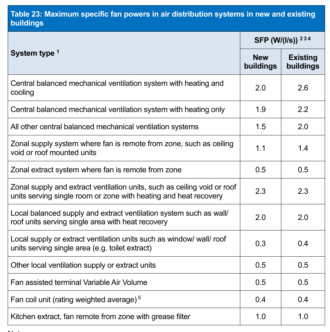
Notes:
1.A central system is one which serves the whole or major areas of the building. A zonal system is one which serves a group of rooms or areas in part of the building and requires ducting. A local system or unit is one which serves a single room or area and does not require ducting.
2.Specific fan power should be calculated in accordance with BS EN 16798-3 at the full design load. For fan coil units, use BS 8850.
3.For balanced supply and extract systems, the maximum SFP includes an allowance for heat recovery and return filter.
4.Where any of the following components are included in the installation, the maximum SFP may be increased:
•High-efficiency particulate air (HEPA) filter: add 1.0 W/(l.s).
Page 49
#Source page 49
•Humidifier/dehumidifier: add 0.1 W(l.s).
•Active chilled beams: add 0.3 W/(l.s).
•Transpired solar collector: add 0.3W/(l·s)
For example, a central balanced mechanical ventilation system with heating and cooling, HEPA filter and humidifier, installed in a new building –
SFP = 2.0 + 1.0 + 0.1 = 3.1 W/(l.s)
5.The rating weighted average is calculated by the following formula:
P mains,1 x SFP 1 + P mains,2 x SFP 2 + Pmains,3 x SFP 3 + …
Pmains ,1 + P mains,2 + P mains,3 +… where Pmains is useful power supplied from the mains in W.
| Table 24: Recommended minimum controls for air distribution systems in new and existing buildings from BS EN 15232 | ||
| System type | Controls package | |
| Central mechanical ventilation with heating, cooling or heat recovery | Air flow control at room level | Time control |
| Air flow control at air handler level | On/off time control | |
| Heat exchanger defrosting control | Defrost control so that during cold periods ice does not form on the heat exchanger | |
| Heat exchanger overheating control | Overheating control so that when the system is cooling and heat recovery is undesirable, the heat exchanger is stopped, modulated or bypassed | |
| Supply temperature control | Variable set point with outdoor temperature compensation | |
| Central mechanical ventilation with heating or heat recovery | Air flow control at room level | Time control |
| Air flow control at air handler level | On/off time control | |
| Heat exchanger defrosting control | Defrost control so that during cold periods ice does not form on the heat exchanger | |
| Heat exchanger overheating control | Overheating control so that when the system is cooling and heat recovery is undesirable, the heat exchanger is stopped, modulated or bypassed | |
| Supply temperature control | Demand control. | |
| Zonal / Local | Air flow control at room level | On/off |
10.4 Heat recovery in air distribution systems in new and existing buildings
#Source page 50
Air supply and extract ventilation systems including heating or cooling should be fitted with a heat recovery system where this is technically feasible. The application of a heat recovery system is described in 6.5 of BS EN 13053. The methods for testing air-to-air heat recovery devices are given in BS EN 308.
The minimum dry heat recovery efficiency with reference to the mass flow ratio 1:1 should be no less than that recommended in Table 38.
| Table 25: Recommended minimum dry heat recovery efficiency for heat exchangers in new and existing buildings | |
| Heat exchanger type | Dry heat recovery efficiency (%) |
| Plate heat exchanger | 50 |
| Heat pipes | 60 |
| Thermal wheel | 65 |
| Run around coil | 45 |
10.5 Calculating the specific fan power for SBEM
SBEM assumes a value of SFP for the fan coil system, so this figure should not be added to the SFP for the fan coil units when entering the data into SBEM.
HEPA filtration is recognised as an option in SBEM. The pressure drop can be specified or SBEM will assume a default value from the NCM activity database.
Section 11: Pipework and ductwork insulation
#Source page 51
11.1 Introduction
This section gives guidance on insulating pipework and ducting serving space heating, hot water and cooling systems in new and existing buildings to meet relevant energy efficiency requirements in the building regulations.
The insulation of pipework and ducting is essential to minimise heating system heat losses and cooling system heat gains. For cooling systems, it is also important to ensure that the risk of condensation is adequately controlled.
The guidance in this section covers insulation for the following types of pipework and ductwork serving space heating, domestic hot water and cooling systems:
•pipework: direct hot water, low, medium and high temperature heating, and cooled
•ductwork: heated, cooled and dual-purpose heated and cooled.
11.2 Insulation of pipes and ducts in new and existing buildings
To optimise the effectiveness of the supply of heat or cooling, hot water pipework and warm or cold air ductwork should be insulated in all areas inside and outside the building. Insulation of pipes and ducts serving heating and cooling systems should meet the following recommended minimum standards.
Direct hot water and heating pipework
Pipework serving space heating and hot water systems should be insulated in all areas outside of the heated building envelope. In addition, pipes should be insulated in all voids within the building envelope and within spaces which will normally be heated, if there is a possibility that those spaces might be maintained at temperatures different to those maintained in other zones. The guiding principles are that control should be maximised and that heat loss from uninsulated pipes should only be permitted where the heat can be demonstrated as ‘always useful’.
Insulation should be designed so that the permissible heat losses in BS 5422 for hot water services in non-domestic buildings are not exceeded. For low temperature space heating and hot water systems, the heat losses shown in Table 26a & 26b should achieve this. Insulation thickness should be calculated in accordance with BS EN ISO 12241.
Page 52
#Source page 52
Table 26a: Minimum pipework insulation thicknesses for low temperature hot water space heating systems
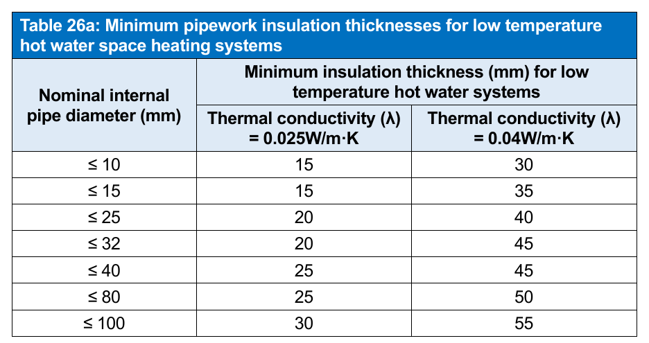
Note: Insulation thicknesses designed to achieve permissible heat losses from BS 5422 for heating systems at ≤ 95 ºC. Thicknesses are for low-emissivity faced insulation. Otherwise consult BS 5422.
Table 26b: Minimum pipework insulation thicknesses for domestic hot water services
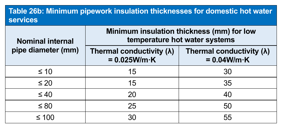
Note: Insulation thicknesses designed to achieve permissible heat losses from BS 5422 for heating systems at 60 ºC. Thicknesses are for low-emissivity faced insulation. Otherwise consult BS 5422.
Provision should also be made for control of condensation. Advice on this can be found in the Thermal Insulation Manufacturers and Suppliers Association’s ‘HVAC Guidance for Achieving Compliance with Part L of the Building Regulations’.
Heating and cooling ductwork
Ducting should be insulated along its whole length in order to provide the necessary means of limiting heat gains or heat losses. The heat losses or gains per unit area should not exceed the values in Table 27. Where ducting may be used for both heating and cooling, the limits for chilled ducting should be adopted since these are more onerous (heat gains are shown as negative values). As with pipework, additional insulation may be required to provide adequate condensation control.
Page 53
#Source page 53
| Table 27: Recommended maximum heat losses and gains for ducts delivering air for heating and/or cooling | ||
| Heating duct | Cooling / dual-purpose duct | |
| Heat transfer (W/m²) | 16.34 | -6.45 |
| Indicative insulation thickness (mm) | 21 | 36 |
Note: Insulation thicknesses should be calculated according to BS EN ISO 12241 using the following standardised assumptions:
•Horizontal duct at 35 °C, with 600 mm vertical sidewall in still air at 15 °C
•Horizontal duct at 13 °C, with 600 mm vertical sidewall in still air at 25 °C
Thicknesses apply for low-emissivity faced insulation with a thermal conductivity of 0.025 W/(m.K) or better. Otherwise consult BS 5422.
Section 12: Lighting
#Source page 54
12.1 Introduction
This section provides guidance on specifying lighting for new and existing non-domestic buildings to meet relevant energy efficiency requirements in the building regulations. There are two alternative approaches, applicable both to systems in new buildings and to replacement systems in existing buildings.
The guidance in this section applies to the following types of lighting:
•general interior lighting
•display lighting.
12.2 Key terms
Absence detection is a type of control which switches the lighting off, or dims it down, after the space becomes unoccupied, but where switching on is done manually.
Circuit-watt is the power consumed in lighting circuits by lamps and, where applicable, their associated control gear (including transformers and drivers) and power factor correction equipment.
High excitation purity light sources are colour-tuneable light sources that can be set to at least the colours listed below and which have for each of these colours, measured at the dominant wavelength, the minimum excitation purity shown. Intended for use in applications requiring high-quality coloured light.
| Colour | Dominant wavelength (nm) | Minimum excitation of purity (%) |
|---|---|---|
| Blue | 440-490 | 90 |
| Green | 520-570 | 65 |
| Red | 610-670 | 95 |
Lamp lumens means the sum of the average initial (100 hour) lumen output of all the lamps in the luminaire.
Lamp lumens per circuit-watt is the total lamp lumens summed for all luminaires in the relevant areas of the building, divided by the total circuit-watts for all the luminaires.
Light source lumens is the sum of the average initial (100 hour) lumen output of all the light sources in a luminaire. This does not include any losses or inefficiencies of the luminaire.
LOR is the light output ratio of the luminaire, which means the ratio of the total light output of the luminaire under stated practical conditions to that of the lamp or lamps contained in the luminaire under reference conditions.
Luminaire lumens per circuit-watt is the (lamp lumens x LOR) summed for all luminaires in the relevant areas of the building, divided by the total circuit-watts for all the luminaires.
LENI (Lighting Energy Numerical Indicator) is a measure of the performance of lighting in terms of energy per square metre per year (kWh/m2/year), based on BS EN 15193:2007 – ‘Energy performance of buildings. Energy requirements for lighting’.
12.3 Lighting in new and existing buildings
#Source page 55
Presence detection is a type of control which switches the lighting on when someone enters a space, and switches it off, or dims it down, after the space becomes unoccupied.
12.3 Lighting in new and existing buildings
Lighting should be designed to achieve lighting levels appropriate to the activity in the space, based on the CIBSE SLL Lighting Handbook or an equivalent design guide. Spaces should be within the recommended illuminance range and should not be over-illuminated.
In smaller spaces, where total lighting power is likely to be low (toilets, store rooms, etc.) there is no expectation that lighting calculations should be produced.
General Lighting - efficacy
General lighting should have an average luminaire efficacy of 95 luminaire lumens per circuit-watt or demonstrate an equivalent efficacy using the Lighting Energy Numeric Indicator (LENI) method (see section 12.4).
Display Lighting - efficacy
Display lighting should have either:
•an average light source efficacy of 80 light source lumens per circuit-watt
•a rated power usage no greater than 0.3 W/m² in each space
•the LENI method, following advice in section 12.4.
High excitation purity light sources should have an average light source efficacy of 65 light source lumens per circuit-watt.
Lighting controls
Lighting controls in new and existing buildings should follow the guidance in BRE Digest 498 – ‘Selecting lighting controls’.
Unoccupied spaces should have automatic controls to turn the general lighting off when the space is not in use (e.g. through presence or absence detection). Occupied spaces should have automatic controls where suitable for the use of the space.
General lighting in occupied spaces should have daylight controls (e.g. photo-switching and dimming) for parts of the space which are likely to receive high levels of natural light.
Display lighting, where provided, should be controlled on dedicated circuits that can be switched off at times when it is not needed for the purpose for which it is provided.
Lighting metering
The lighting should be metered to record its energy consumption in accordance with the minimum standards in Table 28.
12.4 Lighting Energy Numerical Indicator (LENI)
#Source page 56
| Table 28: Recommended minimum standards for metering of general and display lighting in new and existing buildings | |
| Metering solution | |
| Metering for general or display lighting | Either: • kWh meters on dedicated lighting circuits in the electrical distribution; or • local power meter coupled to or integrated in the lighting controllers of a lighting or building management system; or • a lighting management system that can calculate the consumed energy and make this information available to a building management system or in an exportable file format. (This could involve logging the hours run and the dimming level, and relating this to the installed load). |
12.4 Lighting Energy Numerical Indicator (LENI)
An alternative to complying via a minimum efficacy level in Section 12.3 is to follow the Lighting Energy Numerical Indicator (LENI) method.
The LENI method calculates the performance of lighting in terms of energy per square metre per year. The approach described below must be followed in calculating the LENI for a lighting scheme. The LENI should not exceed the lighting energy limit specified in Table 44 for a given illuminance and hours run.
Design the lighting
The first step to energy efficient lighting is to design the lighting installation in a way that meets all of the users’ needs for the space under consideration. Recommendations for appropriate illuminance values and other lighting requirements may be found in BS EN 12464-1 and in the Society of Light and Lighting (SLL) Code for Lighting. The SLL Handbook provides practical advice on how to design lighting for a number of different applications7.
Step 1 - Determine the lighting energy limit – from Table 29.
If display lighting is used, then the lighting energy limit may be increased by the value given for normal display lighting for the area of the room where display lighting is used.
Step 2 - Calculate the parasitic energy use (E p )
If the parasitic energy use is unknown, an allowance of 0.3 W/m2 should be made for any control system. If no lighting control system is used, then Ep = 0.
Step 3 - Determine the total power of lighting (P l )
This is the total power in watts consumed by the luminaires within a space.
Step 4 - Determine the occupancy factor (Fo )
Page 57
#Source page 57
If no automatic control is used, then Fo = 1. If controls turn off the lights within 20 minutes of the room being empty, then Fo = 0.8.
Step 5 - Determine the factor for daylight (Fd )
If no daylight-linked dimming system is used, then Fd = 1. If the electric lighting dims in response to daylight being available, then in areas with adequate daylight Fd = 0.8. This may be taken as all areas within 6 m of a window wall or in areas where 10% or more of the roof is translucent or made up of rooflights.
Step 6 - Determine the constant illuminance factor (Fc)
Systems that control the lighting in this way have Fc = 0.9, and those that do not have Fc = 1.
Step 7 - Determine the daytime energy use (E d )
The day time energy use is: E d = P l x Fo x Fd x Fc x Td 1000
Step 8 - Determine the night time energy use (E n )
The night time energy use is: E n = P l x Fo x Fc x Tn 1000
Step 9 - Calculate total energy (kWh) per square metre per year (LENI)
The total energy per square metre per year is the sum of the daytime, night- time and parasitic energy uses per year divided by the area (A), as set out in the formula below:
LENI = E p + E d + E n
A
Table 29: Recommended maximum LENI (kWh per square metre per year) in new and existing buildings
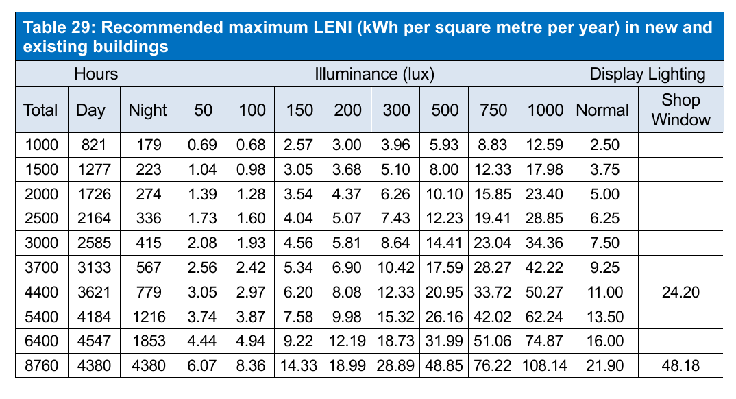
Section 13: Heating and cooling system circulators and water pumps
#Source page 58
13.1 Introduction
Heating and cooling water in HVAC systems of non-domestic buildings can circulate for extensive periods and be responsible for considerable energy use.
This section provides guidance on specifying:
•heating system glandless circulators, both standalone and integrated in products
•heating and cooling system water pumps
to limit their energy consumption and meet relevant energy efficiency requirements in the Building Regulations. The guidance covers circulators and water pumps when used in closed systems.
13.2 Key terms
Heating system glandless circulator means a pump used to circulate hot water in closed circuit heating systems. The glandless (or wet rotor) circulator is a centrifugal pump with an integral motor and no mechanical seal. It can have an integrated motor drive unit for variable speed operation.
Water pump (also known as ‘dry rotor’ or ‘direct coupled’ pump) means a centrifugal pump driven by an electric motor and generally having mechanical seals. Common pump types include in-line, end suction and vertical multi-stage. The first two are usually single-stage pumps having single-entry volute. By design they can all be used as circulators for all HVAC applications depending on configuration and duty.
13.3 Glandless circulators and water pumps in new and existing buildings
Heating system glandless circulators and heating and cooling system water pumps in new and existing buildings should meet the following recommended minimum standards
•Variable speed glandless circulators should be used on variable volume systems.
•If a water pump is used on a closed loop circuit and the motor is rated at more than 750 W, then it should be fitted with or controlled by an appropriate variable speed controller on any variable volume system. On water pump booster sets with an open loop circuit, the static head should be checked before an appropriate variable speed controller is used.
13.4 Supplementary information
Further information and guidance is available from www.bpma.org.uk where a list of approved glandless circulators and water pumps can be found.
Section 14 – Building Automation and Control Systems.
#Source page 59
14.1 Introduction
This section provides guidance on the provision of Building Automation and Control Systems (BACS) in new and existing buildings to meet relevant energy efficiency requirements in the building regulations.
14.2 Key terms
Building Automation and Control System means a system comprising all products, software and engineering services that can support energy efficient, economical and safe operation of heating, ventilation and air conditioning systems through automatic controls and by facilitating the manual management of those building systems.
14.3 Building Automation and Control Systems
If a new building has a space heating or air-conditioning system with an effective rated output of greater than to 290 kW, a Building Automation and Control System should be installed.
If an existing building has a space heating or air-conditioning system with an effective rated output greater than 290 kW, a Building Automation and Control System being replaced or installed should provide the functions set out below.
The above provisions also apply to buildings containing heating and air-conditioning systems which are combined with ventilation systems.
Note: in situations where neither of the above situations occur, consideration should be given to providing centralised switches to allow the facilities manager to switch off appliances when they are not needed. Where appropriate, these should be automated (with manual override) so that energy savings are maximised. Consideration should be given to the power requirements of essential (e.g. life safety) systems.
Determining the effective rated output
The effective rated output is the combined output of the equipment in the building which is provided for heating or cooling the internal space in normal operation, for the comfort of occupants.
For air-conditioning systems, the effective rated output should include the combined maximum output of both of the following, as specified by the manufacturer.
•Air-conditioning systems
•Air-conditioning systems combined with or as part of a ventilation system.
For heating systems, the effective rated output should include the combined maximum output of all the following, as specified by the manufacturer.
•Primary space heating systems.
•Space heating systems combined with or as part of a ventilation system.
•Secondary space heating systems.
Assessment of effective rated output does not include any of the following.
•Heating or cooling equipment only intended for emergency or occasional backup use.
Page 60
#Source page 60
•Heating equipment for frost protection.
•Heating for domestic hot water.
•Heating or cooling for industrial processes.
If the building is heated through supply of heat from a heat network, the effective rated output should be based on the capacity of the equipment installed in the building, making reasonable assumptions for the operation of the heat network, including flow temperatures.
The requirements are based on the final installed capacity of the heating or air-conditioning system. When estimating the effective rated output at design stage, designers should make allowances for the final installed capacity, including potential oversizing and equipment substitution.
Installed system - functions
Where a Building Automation and Control System is installed, it should comply with BS EN ISO 16484 and provide the following functions.
•Continuously monitor, log, analyse and allow for adjusting of energy use.
•Benchmark the building energy efficiency, detect losses in efficiency of technical building systems, and inform the person responsible for the facilities or building management about opportunities for energy efficiency improvement.
•Allow communication with connected technical building systems and other appliances inside the building and be interoperable with technical building systems across different types of proprietary technologies, devices and manufacturers.
Note: A BS EN 15232 Class A Rated type system would meet the above requirements.
Where a building automation and control system is installed, as well as meeting the requirements above, its control capabilities should be appropriate for the building, its expected usage, the expected technical knowledge of the building automation and control system user, and the building services specification. The system should be appropriately sized.
Section 15 – Self-Regulating Devices
#Source page 61
15.1 Introduction
This section provides guidance on the provision of self-regulating devices, such as room and emitter thermostats, in new and existing buildings to meet relevant energy efficiency requirements in the building regulations.
15.2 Key terms
Self-regulating device means a device or system that automatically controls the output of heating and/or cooling emitters to independently control the temperature in each room or, (where justified, a heating zone) where heating and/or cooling is provided by a fixed building service.
15.3 Self-regulating devices
For heating and cooling systems in new buildings, each room or, where justified in accordance with guidance given below, heating zone should be provided with self-regulating devices for the separate control of heating in the room/zone.
Provision of self-regulating devices
Provision for self-regulating devices can be achieved by providing any of the following solutions:
•An individual networked heat emitter control for each emitter; or
•A thermostat in a room that the heating circuit serves, together with an individual self- regulating device for each heat emitter, such as a thermostatic radiator valve, on all heat emitters outside the room which contains the thermostat.
Thermostatic radiator valves should not be located in the same room as the thermostat.
•An individual room/ heating zone thermostat or fan coil thermostat for each room/heating zone.
•Any other controls which provide the same function as a self-regulating device.
Existing Buildings
For work in existing buildings, when a heat generator, such as a boiler, is replaced, if not already present, self-regulating devices should be installed, where technically feasible and economically feasible, for the separate control of heating in each room served by the heating appliance.
Where it is not technically feasible or economically feasible to install self-regulating devices the requirement does not need to be met. Measures which are not technically feasible include, but are not limited to:
•buildings with very low heat demand (e.g. <10 W/m²).
•buildings with buffer zones for heat absorption or dissipation with high thermal mass.
Note: in normal circumstances, the installation of thermostatic radiator valves in wet central heating systems is likely to be economically feasible.
Page 62
#Source page 62
Option to provide control at zone level
Alternatively, where justified below, heating may be controlled for each heating zone rather than individual rooms where any of the following apply:
•in open-plan spaces in which heating demand and patterns of use are similar across the whole space, sub-zoning of temperature control might not be appropriate. In such cases, the space should be considered as a single heating zone
•where two adjacent rooms have a similar function and heating requirements (e.g. kitchen and utility room).
It might not be possible to equip some heating system types with self-regulating devices for the control of individual rooms. Such systems should only be used where controlling a whole heating zone can be justified.
Section 16: On-site generation of electricity
#Source page 63
Where on-site electricity generation, such as a photovoltaic panel array is installed, systems should be sized appropriately for the site, available infrastructure and the capacity on-site for direct utilisation or storage of generated power.
The system should be specified and installed according to the manufacturer’s instructions to ensure the overall performance of the system meets a reasonable standard.
On-site generation electricity generation should be provided with controls to allow effective operation and monitoring of system performance without the need for user intervention. This is particularly the case where electricity generation and storage systems are used, such as battery storage or PV diverters heating stored hot water.
Where a new installation is replacing an existing system, it should be confirmed whether the existing system formed part of the compliance specification for the building on construction. Where this is the case, the installed annual generation capacity of the new system should not be less than the existing system (as verified by assessment of the original construction specification). This is to provide assurance that the replacement of the existing system does not cause the building to fail to comply with the regulations applicable to its original construction.
Appendix A: Abbreviations
#Source page 64
BMS Building Management System
BS British Standard
BSD Building Standards Division
CHP Combined Heat And Power
CHPQA Combined Heat And Power Quality Assurance
CO 2 Carbon Dioxide
COP Coefficient Of Performance
DHW Domestic Hot Water
LPGEER Energy Efficiency Ratio
EN European Norm (Standard)
ESEER European Seasonal Energy Efficiency Ratio
HEPA High-Efficiency Particulate Absorption
HVAC Heating Ventilation And Air Conditioning
LENI Lighting Energy Numeric Indicator
LPG Liquefied Petroleum Gas
NCM National Calculation Methodology
PSEER Plant Seasonal Energy Efficiency Ratio
QI Quality Index
SAP Standards Assessment Procedure
SBEM Simplified Building Energy Model
SCOP Seasonal Coefficient Of Performance
SEER Seasonal Energy Efficiency Ratio
SFP Specific Fan Power
SI Statutory Instrument
SPF Seasonal Performance Factor
TRV Thermostatic Radiator Valve
VAV Variable Air Volume
VRF Variable Refrigerant Flow
Appendix B: List of referenced standards and publications
#Source page 65
British, European and International Standards
BS 5422:2009 – ‘Method for specifying thermal insulating materials for pipes, tanks, vessels, ductwork and equipment operating within the temperature range -40°C to +700°C’.
BS 8550:2020 – ‘Fan coil unit performance. Determination of specific fan power. Test method’.
BS EN 26: 2015 – ‘Gas fired instantaneous water heaters for the production of domestic hot water, fitted with atmospheric burners’.
BS EN 89: 2015 – ‘Gas-fired storage water heaters for the production of domestic hot water’.
BS EN 308:2022 – ‘Heat exchangers. Test procedures for establishing performance of air to air heat recovery components’.
BS EN 1507: 2006 – ‘Ventilation for buildings. Sheet metal air ducts with rectangular section. Requirements for strength and leakage’.
BS EN 1886:2007 – ‘Ventilation for buildings. Air handling units. Mechanical performance’
BS EN 12237: 2003 – ‘Ventilation for buildings. Ductwork. Strength and leakage of circular sheet metal ducts’.
BS EN 12464-1:2011 – ‘Light and lighting. Lighting of work places. Indoor work places’
BS EN 12809:2001+ A1:2004 – ‘Residential independent boilers fired by solid fuel. Nominal heat output up to 50 kW. Requirements and test methods’
BS EN 12831-1: 2017 – ‘Energy performance of buildings. Method for calculation of the design heat load - Space heating load, Module M3-3’.
BS EN 13053:2019 – ‘Ventilation for buildings. Air handling units. Rating and performance for units, components and sections’.
BS EN 13403: 2003 – ‘Ventilation for buildings. Non-metallic ducts. Ductwork made from insulation ductboards’.
BS EN 13842:2004 – ‘Oil-fired convection air heaters – stationary and transportable for space heating’.
BS EN 16798-3: 2017 – ‘Energy performance of buildings. Ventilation for buildings - For non- residential buildings. Performance requirements for ventilation and room-conditioning systems (Modules M5-1, M5-4)’.
BS EN 14511-2: 2011 – ‘Air conditioners, liquid chilling packages and heat pumps with electrically driven compressors for space heating and cooling. Test conditions’
BS EN 14825:2013 – ‘Air conditioners, liquid chilling packages and heat pumps with electrically driven compressors for space heating and cooling. Testing and rating at part load conditions and calculation of seasonal performance’
BS EN 15193:2007 – ‘Energy performance of buildings. Energy requirements for lighting’.
BS EN 15232:2017 – ‘Energy performance of buildings – impact of building automation, controls and building management’.
Page 66
#Source page 66
BS EN 15450:2007 – ‘Heating systems in buildings. Design of heat pump heating systems’.
BS EN 15502-2BS EN 17082:2019 – ‘Domestic and non-domestic gas-fired forced convection air heaters for space heating not exceeding a net heat input of 300 kW’.
BS EN 17082: 2019 – ‘Domestic and non-domestic gas-fired forced convection air heaters for space heating not exceeding a net heat input of 300 kW’.
BS EN ISO 12241:2008 – 'Thermal insulation for building equipment and industrial Installations. Calculation rules’.
BS EN ISO 16484:2017 + A1: 2020 – ‘Building automation and control systems’.
Other cited guidance documents
Guide B1 (CIBSE)
DW 144 Specification for Sheet Metal Ductwork (BESA, 2016)
Digest 498 – ‘Selecting lighting controls’ (BRE)
CIBSE SLL Lighting Handbook (CIBSE)
Solar heating design and installation guide (CIBSE)