Scotland National calculation methodology modelling guide
Non-domestic buildings: national calculation methodology modelling guide 2022 (Version 1.2 February 2023)
Library captured 10 September 2026 · Source updated 23 February 2023
Page 1
#Source page 1

Building
Standards
Division
National Calculation
Methodology (NCM)
Modelling Guide for Non-Domestic Buildings in Scotland
2022 edition v1.2 – February 2023

Page 2
#Source page 2
Report Prepared by:
Building Standards Division, with contributions from:
•Building Research Establishment (BRE) (www.bre.co.uk)
Building Standards Division
Directorate for Local Government and Housing
The Scottish Government
Denholm House
Almondvale Business Park
Livingston
EH54 6GA
Tel: 0300 244 4000 e-mail: buildingstandards@gov.scot web: http://www.gov.scot/bsd
Applications for reproduction of any part of this publication should be directed to Building Standards Division at the above address.
Note: This document applies to Scotland only. Any reference to the Building regulations in this guide is to the Building (Scotland) Regulations 2004 (as amended). In respect of building regulations, this guidance is applicable to work that is subject to a building warrant submitted on or after 1 February 2023.
© Crown Copyright 2022
Produced by the Buildings Standards Division
First published: June 2022
Version 1.2 (February 2023)
Document Version Control
Title: NCM Modelling Guide for Non-domestic Buildings in Scotland – 2022 edition
Purpose: To provide guidance on compliance with building regulations, namely the application of the calculation methodology used for non-domestic buildings under standards 6.1 and 6.9, as set out in section 6 (energy) of the February 2023 Non- domestic Technical Handbook. This guidance is applicable as described in the note provided above.
| Version | Date | Notes |
| 1.0 | June 2022 | Initial issue in support of the 2022 revision of section 6 (energy) of the Scottish building regulations. |
| 1.1 | August 2022 | Tables 7 & 8 and paragraph 72 updated to align efficiency of heating in HN notional building to match natural gas specification. |
| 1.2 | February 2023 | Differences in building regulations compliance and EPC calculations highlighted in new paragraphs 103 and 148. Confirmation of EPC calculation approach set out in paragraphs 169-172. Table 17, outer pane emissivity corrected. Table 18, all outer pane values updated. |
INTRODUCTION
#Source page 5
1.This document gives guidance on the use of SBEM and other approved software tools comprising the National Calculation Methodology (NCM) when:
a. Demonstrating compliance with the greenhouse gas emissions and energy targets set in respect of non-domestic buildings under standard 6.1 of Scottish building regulations, for building warrants submitted on or after 1 December 2022.
b. Calculating asset ratings as part of preparing Energy Performance Certificates (EPCs) for non-domestic buildings, as required under standard 6.9 of The Building (Scotland) Regulations 2004 (as amended) and regulation 5 or regulation 9 of The Energy Performance of Buildings (Scotland) Regulations 2008 (as amended).
With regards to paragraph 1(b) above, it is expected that Approved Organisations1 have produced separate guidance regarding the forward transmission of the results of these calculations for the purposes of the formal issue of the EPC and the Recommendations Report for the building to the building owners.
2.Separate guidance has been published for the application of the methodology when using approved tools to demonstrate compliance with the applicable regulations in England, Wales and Northern Ireland.
3.This document is subject to regular review and it will be updated as and when the need for additional clarification is identified. This routine updating will help improve the consistency of application of the various tools to the building regulations compliance and energy certification processes. The latest version of the NCM Modelling Guide for Scotland will be available on the website of the Scottish Government Building Standards Division2 (BSD). The guide will refer to a specific edition of the NCM and its implementation in relation to compliance with building regulations from a particular date.
Main Changes to 2022 NCM Guide for Non-Domestic Buildings in Scotland
4.The main changes in the technical requirements of software since the issue of the previous (2015) NCM Modelling Guide are as follows:
•Introduction of a new compliance metric and target based upon delivered energy.
•Removal of the emissions target calculation for new buildings where direct emission heating systems are not present.
•New specifications for the Notional building, which are used to determine the delivered energy and greenhouse gas emissions targets. The latter have been defined to deliver an aggregate emissions reduction across all new non-domestic
Page 6
#Source page 6
•build profile of more than 16% relative to the 2015 edition of Section 6 (Energy) of the Non-Domestic Technical Handbook.
•Simplification of options for the assignment of the Notional blinding specification based upon characteristics of the Actual building, including:
a.Fuel for space and water heating in the Notional building will be assigned as either natural gas, h eat network or electric (heat pump) based upon the fuel and heat solution specified for the Actual building
b.New classification of high and low hot water demand activities to determine the specifications for the Notional building’s water heating system.
c.Standardisation of fabric specification so that it is no longer assigned to each zone depending upon whether a zone is heated and naturally ventilated or heated and mechanically ventilated or cooled.
d.The air infiltration value assigned to the Notional building is no longer dependent upon building area, glazing type or the presence of metal cladding construction.
•Revised approach for accounting for the contribution to calculation of emissions and energy demand due to electricity generated on-site, excluding any exported component from the calculation of benefit for building regulations compliance purposes only. This exclusion is not applied in calculations for other purposes of assessment (EPC and Section 63 Action Plan).
•Revision of compliance calculation where space and water heating is from district heating, applying network characteristics to both Notional and Actual building.
•A new set of UK fuel emission factors and primary energy factors for buildings other than dwellings is provided, including monthly factors for electricity. These are listed in Table 19a to 19d of this document.
•Revised approach for determining the illuminance level for a zone in the Notional building using minimum and maximum lighting levels for the activity type in the NCM Activity Database.*
•Upgrade to the 2016 CIBSE TRY weather data sets.*
•Updated options for HVAC systems in the Actual building and calculation of the corresponding fan energy.*
•Revised approach for calculating the fan energy associated with demand control of ventilation.*
* global changes or improvements made to v.6.0 of the UK NCM.
Approved software tools
#Source page 7
5.Energy calculation software packages for compliance with Section 6 Energy of the Non- Domestic Technical Handbook and certification of energy performance of non-domestic buildings must be approved by the Scottish Government Building Standards Division (BSD) before they can be available for commercial use in Scotland. Information on the validation procedure and the approval scheme is available from the BSD website.
6.The BSD website lists software approved for demonstrating compliance with Section 6 Energy and for calculating asset ratings as part of the production of an Energy Performance Certificate (EPC) in Scotland3. The website also provides a list of Approved Organisations4 who can accredit persons wishing to engage in the production of EPCs for existing non-domestic buildings in Scotland and information on the use of Approved Certifiers of Design for Section 6 (Energy)5 in support of a building warrant application.
7.To be approved, the software tool must satisfy the criteria as published6 by the BSD. These requirements can be updated from time to time and cover a number of generic issues. The software tool has to demonstrate that:
a.The calculations are technically robust and that they cover a necessary minimum set of energy flows.
b.It follows the procedures for demonstrating compliance and issue of Energy Performance Certificates as defined in this document, including the use of the National Calculation Methodology (NCM) databases, the definition of Notional building, and other issues as defined from time to time.
c.It reports a minimum set of output parameters and that these parameters can be passed appropriately to standard modules for:
i. Checking compliance with Section 6 Energy ii. Producing an Energy Performance Certificate (EPC) through lodgement to the Scottish EPC Register7 iii. Deriving a set of recommendations for energy efficiency improvements.
8.In addition to ensuring that the software tools are compatible in terms of technical scope, the approval process also requires software providers to check that the procedural guidance is being followed in terms of the calculation and reporting processes.
Version policy
#Source page 8
9.Approved Dynamic Simulation Model (DSM) software must automatically generate the Notional building from information provided by the user for the Actual building.
10.DSM software must meet or exceed the classification of dynamic modelling under CIBSE AM11.
11.DSM software will be expected to be developed in accordance with ISO 90003:2014 Guidelines for the application of ISO 9001:2008 to computer software.
Version policy
12.All software tools, both the government’s Simplified Building Energy Model (SBEM) and commercial Dynamic Simulation Models (DSMs), evolve with time as improvements are made to the functionality and the quality of the underlying algorithms. This means that it is necessary to have a procedure whereby new versions can be accepted as appropriate for use within the compliance/certification process. The rules in the following paragraphs define the approved procedures.
13.For certifying compliance with Section 6, when submitting a building warrant, the latest version of a software tool should generally be used. However, the previous version of a software tool (i.e. software and NCM databases) may be used for a period not exceeding six months following introduction of a new version, provided a change in regulations does not require use of the current version (as would be the case, for example, for these proposed changes).
14.Whilst the same version of a software tool may be used for any amendment to warrant as for the original warrant, at any stage, applicants can elect to adopt a more recently approved version of the tool, but having elected to use a later version, building developers cannot subsequently revert to using a previous one.
15.For the production of Energy Performance Certificates, the Scottish EPC register will only accept lodgement of data which conforms to the current NCM schema. The approved version of the adopted software tool must be used. An up-to-date list of approved software for EPC lodgement is published by Building Standards Division8.
16.To allow the transfer and reuse of project data from an older to a newer version of the tool, part of the procedure for approving a software tool is that a new version must be backwardly compatible with all previous versions of the tool, i.e. it can either read the data files of previous versions directly, or a file conversion utility must be provided.
Choosing a software tool
17.While all calculation methods involve a degree of simplification, two classes of software tools are available for use for Section 6 compliance checking and EPC generation:
SBEM constraints
#Source page 9
a.SBEM, which is the Simplified Building Energy Model developed for the BSD. This can be applied to any building (irrespective of size) although there are some constraints, as discussed later in this guide. Such constraints are for example, where representation of certain building features require some approximation, entailing additional demands of the assessor’s input time and effort; and
b.Approved Dynamic Simulation Models (DSMs). These are applicable for any building unless approval of an individual DSM specifically excludes certain types of building or building features. They may prove more flexible than SBEM in handling certain building features and are also more suited as design support tools (SBEM is not a design tool, carrying out compliance and certification calculations only).
18.There are a number of approved software interfaces to SBEM. These interfaces must also be approved before the overall software tool can be used. Interface approval as well as software approval is necessary to ensure that procedures are followed appropriately as well as the calculations being carried out correctly.
SBEM constraints
19.All calculation processes involve some approximations and compromises, and SBEM is no exception. The most obvious limitations relate to the use of the CEN monthly heat balance method. This means that processes which vary non-linearly at shorter time- steps have to be approximated or represented by monthly parameters. The HVAC system efficiencies are an example of this.
20.It is, therefore, difficult to give absolute rules about when SBEM can and cannot be used. As broad guidance, it is more likely to be difficult to use SBEM satisfactorily if the building and its systems have features that are not already included in SBEM or have properties that vary non-linearly over periods of the order of an hour.
21.It should be noted that there are also constraints to the use of other software. Any software tool has limits to the building and system options that it can model.
22.Certain building features are not currently modelled explicitly in SBEM and so representing such features in an adequate way will require somewhat cumbersome data preparation work.
23.Examples of building features where such issues can arise include buildings with ventilated double-skin facades and light transfer between highly glazed internal spaces such as atria or light wells
24.Where these features are, found designers can expect the need to pay more attention to manipulating input data and recording any assumptions made and their justifications.
25.It is recommended that users make full use of features such as, the ‘multiplier’ function in SBEM and merging of all contiguous similar areas (see section 7.4), in order to
COMPLIANCE WITH BUILDING REGULATIONS
#Source page 10
•generally avoid creating more zones than necessary, enhance clarity of the models, and help with quality audits. The default version of the SBEM engine runs on 64-bit Windows operating systems generally avoid creating more zones than necessary, enhance clarity of the models, and help with quality audits. The default version of the SBEM engine runs on 64-bit Windows operating systems generally avoid creating more zones than necessary, enhance clarity of the models, and help with quality audits. The default version of the SBEM engine runs on 64-bit Windows operating systems generally avoid creating more zones than necessary, enhance clarity of the models, and help with quality audits. The default version of the SBEM engine runs on 64-bit Windows operating systems generally avoid creating more zones than necessary, enhance clarity of the models, and help with quality audits. The default version of the SBEM engine runs on 64-bit Windows operating systems
COMPLIANCE WITH BUILDING REGULATIONS
26.Compliance with standard 6.1 of Section 6 Energy requires that a new non-domestic building must show, by calculation, that it is designed to limit both delivered energy demand and greenhouse gas emissions. This is achieved by demonstrating that the building as designed will have:
a.energy demand no greater than a Target Delivered Energy Rate (TDER), i.e. the Building Delivered Energy Rate (BDER) is less than or equal to the TDER11, and
b.emissions no greater than a Target Emission Rate (TER), i.e. the Building Emission Rate (BER) is less than or equal to the TER.
27.The TER and TDER for the 2022 calculation which supports standard 6.1 of Section 6 Energy is derived by defining a target based on the performance of a ‘Notional building’ and the following procedure must be followed in order to establish these targets. This approach is adopted to avoid the need to define system models appropriate to different types of building. It also ensures a consistent approach to the target setting process.
28.The 2022 amendments to building regulations introduce a definition of ‘direct emission heating systems’. This is further explained in guidance to standard 6.1 in the Non- domestic Technical Handbook. As of 2022, the requirement to calculate and demonstrate compliance with a Target Emission Rate is no longer applied to new buildings which do not use direct emission heating or cooling systems. The Target Delivered Energy Rate must be met for all new buildings irrespective of their heating/cooling systems.
THE NOTIONAL BUILDING
29.As specified in the guidance under standard 6.1 of Section 6 (Energy), the Notional building has the same size, shape, and zoning arrangements as the Actual building, with the same conventions relating to the measurement of dimensions (see Table 20).
Activity glazing class
#Source page 11
30.Each space must contain the same activity (and therefore the same activity parameter values) as proposed for the equivalent space in the Actual building. The activity in each space must be selected from the list of activities defined in the NCM Activity Database.
31.The Notional building must be given the same orientation and be exposed to the same weather data as the Actual building. For DSM software, the Notional building must be subject to the same site shading from adjacent buildings and other topographical features as are applied to the model of the Actual building.
32.Whatever building services type (heating, ventilation, cooling) is specified in a zone in the Actual building must also be provided in the corresponding zone in the Notional building. Note that in some zones, heating need not be provided, even though the NCM Activity Database specifies a heating set-point. For example, the Actual building may contain an unheated stairwell or atrium space. The corresponding zones in the Notional building must also be unheated. However, if heating were provided to either of these spaces in the Actual building, then heating must correspondingly be specified in the Notional building, and then both buildings must heat those spaces to the heating set-point specified for the zone type in the NCM Activity Database.
33.The Notional building specifications are assigned based upon the main space and water heating fuel and heat solution chosen for the Actual building and are applied at a zone level within the building. There are three Notional building specifications which differ only in their treatment of space and water heating elements and allocation of on- site generation (via assignment of a photovoltaic array).
34.Any fixed building services system not covered by Section 6 (Energy) must be ignored in both the Actual and Notional buildings.
Activity glazing class
35.In the Notional building, the activity assigned to each zone determines whether it will have access to daylight through windows, roof-lights, or no glazing at all (i.e. no access to daylight), regardless of the type of glazing applied to the equivalent zone in the Actual building. The glazing type assigned to each NCM activity is determined in the “activity” table from the NCM Activity database in the “DRIVER2A” field (0 for activity with no daylight, i.e. unlit, 1 for side-lit activity, and 2 for top-lit activity).
36.The assignment of glazing type is used to apportion elements of fabric to the external envelope of the Notional building and in calculation of solar gain and overheating risk. Note that glazing type is no longer used to vary other aspects of building specifications such as fabric U-values.
Building fabric
#Source page 12
37.The U-values in the Notional building must be as specified in Table 1. Taking into account guidance in BR 44312, all U-values should be calculated in accordance with BS EN ISO 6946: 2017, where the U-values calculation methods are inclusive of repeating thermal bridges.
38.The effective thermal capacity of the construction elements, κm (kappa-m) value, in the Notional building must be as shown in Table 2. For DSMs the information in the NCM Construction Database includes the necessary technical parameters to evaluate the impact of thermal capacity. The thermal mass of windows should be ignored.
| Table 1: U-values of construction elements in the Notional building (W/m².K) | |
| Element | U-value (W/m²K) |
| Roofs | 0.11 |
| Walls ¹ | 0.15 |
| Floors | 0.13 |
| Windows / Roof Windows / Pedestrian Doors | 1.20 |
| Roof-lights 2 3 | 1.9 |
| Vehicle access and similar large doors | 1.3 |
| High usage entrance doors ⁴ | 1.9 |
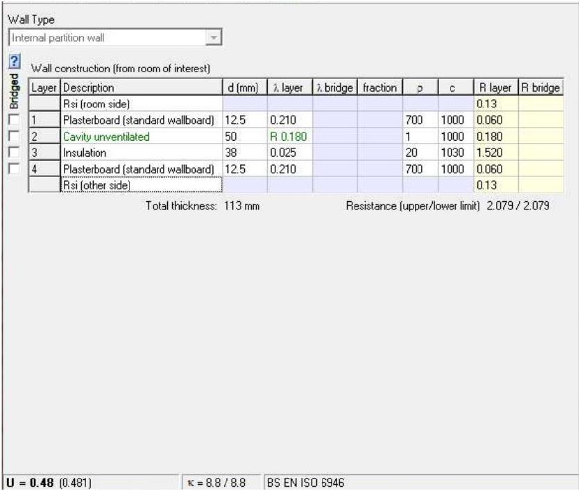
| Internal walls | 0.48 |
| Internal windows | 3.85 |
| Internal ceilings | 1.00 |
| Notes: 1. Any part of a roof having a pitch greater or equal to 70º is considered as a wall. 2. U-value of rooflights is the overall U-value including the frame and edge effects, and already includes adjustment for horizontal orientation as detailed in BR 443: 2019. 3. All the roof-lights in the Notional Building are assumed to be conical or domed, and hence, for the purposes of heat transfer calculations, their developed to projected ratio is set to 1.3, i.e., the area of the roof-light is 1.3 times the area of the opening in the roof. 4. Pedestrian entrance doors, characterised by frequent use as a main entrance, robust construction and powered operation, usually installed in a lobby configuration. |
Page 13
#Source page 13
| Table 2: Thermal capacity of construction elements in the Notional building | |
| Element | Effective thermal capacity (kJ/m²K) |
| Roofs | 88.3 (1.40 if metal-clad) |
| Walls | 21.8 (1.40 if metal-clad) |
| Floors | 77.7 |
| Vehicle access and similar large doors | 2.1 |
| Pedestrian doors and high usage entrance doors | 54.6 |
| Internal wall | 8.8 |
| Internal floor/ceiling | 71.8 from above, 66.6 from below |
| Notes: Thermal capacity calculation in EN ISO 13790:2004. Any part of a roof having a pitch greater or equal to 70º is considered as a wall. |
39.Zones in the Notional building which use activity types flagged as involving metal cladding in the NCM Activity database will use metal-clad construction elements and the associated Psi values from Table 3 for thermal bridges. Whether or not the activity involves metal cladding is determined in the “activity” table from the NCM Activity database in the “METAL_CLADDING” field (0 for activity with no metal-clad constructions, and 1 for activity with metal-clad constructions).
40.For SBEM, the thermal capacity of the construction elements must be as defined in Table 2. For DSM software, the construction details in Appendix C provide the necessary technical parameters to account for the effect of thermal capacity. The thermal mass of windows should be ignored.
41.The Notional building does not have curtain walling or display windows, even when curtain walling or display windows are present in the Actual building.
42.Smoke vents and other ventilation openings, such as intake and discharge grilles, must be disregarded in the Actual and Notional buildings, and their area substituted by the relevant (i.e. immediately surrounding) opaque fabric (roof or wall).
43.For SBEM and DSM software, the non-repeating thermal bridge heat losses for each element (including windows, etc.) must be allowed for by a method that satisfies BS EN ISO 14683 or by adding 10% to the standard area-weighted average U-values, of the Notional Building. Whichever method is applied must be applied to both Notional and Actual building calculations (see paragraph 106 for the latter). Note that the U-values as given in Table 1, and the corresponding construction elements in the database, DO NOT include this allowance so the calculation tool must make the adjustment explicitly.
44.Where an equivalent method that satisfies BS EN ISO 14683 is used to take account of non-repeating thermal bridges, the Psi values for the Notional building will use the values from Table 3.
Page 14
#Source page 14
| Table 3: Psi values for the Notional building (W/mK) | ||
|---|---|---|
| Type of junction | Involving metal cladding | Not involving metal- cladding |
| Roof to wall | 0.28 | 0.12 |
| Wall to ground floor | 1.0 | 0.16 |
| Wall to wall (corner) | 0.2 | 0.09 |
| Wall to floor (not ground floor) | 0.0 | 0.07 |
| Lintel above window or door | 1.0 | 0.30 |
| Sill below window | 0.95 | 0.04 |
| Jamb at window or door | 0.95 | 0.05 |
45.Special considerations apply to ground floors, where the U-value is a function of the perimeter/area ratio. The following adjustments must be made13:
a.If the calculated value is greater than 0.13 W/m²K, the value of 0.13 W/m²K must be used in the Notional building.
b.If the calculated value with no added insulation is less than 0.13 W/m²K, this lower value must be used in the Notional building.
46.When modelling an extension, the boundary between the existing building and the extension must be disregarded (i.e. assume no heat transfer across it).
47.Zones in the Notional building will use the air permeability value of 4 m³/h per m² of envelope area at 50 Pa. The calculation method used to estimate the infiltration rate must use the air permeability as the parameter defining the envelope leakage. For compliance and certification purposes, the same method must be used in the Actual and Notional buildings. Acceptable methods include:
a.The method specified in the SBEM Technical Manual14, which is taken from EN 1524215.
b.Other methods that use a relationship between infiltration rate and air permeability and are set out in national or international standards or recognised UK professional guidance documents which relate average infiltration rate to envelope permeability. An example of the latter would be tables 4.16 to 4.23 of CIBSE Guide A (2021).
Methods that use flow networks are not acceptable for compliance or certification purposes as there is no simple way to check that the permeability of the Notional building delivers the required permeability standard.
Areas of windows, doors, and rooflights
#Source page 15
48.The areas of windows, doors, and rooflights in the Notional building must be determined as set out in the following sub-paragraphs and must also conform to the measurement conventions set out in Annex A, paragraph 203 and Table 20.
a.Copy the areas of high usage entrance, pedestrian, and vehicle access doors that exist in the corresponding element of the Actual building.
b.In the Notional building, high usage entrance, pedestrian, and vehicle access doors must be taken as being opaque (i.e. with zero glazing) and use the U-values in Table 1.
c.If the total area of these elements is less than the appropriate allowance for glazing from Table 4, the balance must be made up of windows or rooflights as appropriate.
d.If the total area of the copied elements exceeds the allowance for glazing from Table 4, the copied areas must be retained but no windows or rooflights added.
e.For DSM software, the shape of windows in side-lit activities should be modelled as a full facade width window with sill height of 1.1 m. Where doors have been copied across from the Actual building, the window will occupy the remaining facade width, and the height adjusted such that the total area of opening areas still satisfies Table 4.
49.Display windows in the Actual building are not copied across into the Notional building and their area is substituted by the relevant (i.e. immediately surrounding) wall.
| Table 4: Glazing in the Notional building | ||||
|---|---|---|---|---|
| Activity glazing type | Glazing area (glass + frame) | g-value (EN ISO 410) | Frame factor | Visible light transmittance |
| Side-lit | Exposed facades will have windows with area that is the lesser of either: 1.5 m high x full facade width or 40% of exposed facade area | 50% | 10% | 77% |
| Top-lit | 12% of exposed roof area will be made up of rooflights* | 52% | 15% | 57% |
| Unlit | No windows or rooflights | n/a | ||
| *The number of rooflights per roof element is determined using the following equation: 𝑵𝑵𝒐𝒐𝒐𝒐𝒐𝒐 𝑵𝑵𝒓𝒓𝑵𝑵𝑵𝑵𝑵𝑵𝒆𝒆𝒓𝒓 𝒂𝒂𝑵𝑵𝑵𝑵𝒂𝒂 𝑵𝑵𝑵𝑵𝑵𝑵𝑵𝑵𝑵𝑵𝑵𝑵 𝒐𝒐𝒐𝒐 𝑵𝑵𝒐𝒐𝒐𝒐𝒐𝒐𝒓𝒓𝒓𝒓𝒓𝒓𝒓𝒓𝒓𝒓𝒓𝒓 𝒑𝒑𝑵𝑵𝑵𝑵 𝑵𝑵𝒐𝒐𝒐𝒐𝒐𝒐 𝑵𝑵𝒓𝒓𝑵𝑵𝑵𝑵𝑵𝑵𝒆𝒆𝒓𝒓 = 𝟏𝟏. 𝟔𝟔𝟔𝟔 × 𝒛𝒛𝒐𝒐𝒆𝒆𝑵𝑵 𝒓𝒓𝑵𝑵𝒓𝒓𝒓𝒓𝒓𝒓𝒓𝒓 𝟐𝟐 � � 𝐜𝐜𝐜𝐜𝐜𝐜(𝒂𝒂𝒆𝒆𝒓𝒓𝒓𝒓𝑵𝑵 𝒐𝒐𝒐𝒐 𝒓𝒓𝒓𝒓𝒐𝒐𝒑𝒑𝑵𝑵) The number of rooflights should be rounded to the nearest integer and be greater than zero. Where the roof element is sloped, the zone height should be the height to the eaves or lowest point of the roof element. |
HVAC and Hot Water systems
#Source page 16
50.DSM software are required to use the glass data provided in Table 5 & 6 to model the glazing specification required in Table 4, where Tsolar is the direct solar transmittance, Tvisible is the direct visible light transmittance, Rsolar is the solar reflectance, and Rvisible is the visible light reflectance. The subscripts 1 and 2 refer to the outer and inner surfaces of each pane of glass, respectively.
| Table 5: Glass properties for side-lit glazing in the notional building. | |||||||||
|---|---|---|---|---|---|---|---|---|---|
| Thickness | Tsolar | Rsolar1 | Rsolar2 | Tvisible | Rvisible1 | Rvisible2 | Emissivity 1 | Emissivity 2 | |
| Outer pane | 6.1 mm | 0.529 | 0.229 | 0.332 | 0.859 | 0.075 | 0.059 | 0.840 | 0.033 |
| Cavity | 16.0 mm | Argon gas fill | |||||||
| Inner pane | 5.7 mm | 0.786 | 0.071 | 0.071 | 0.891 | 0.081 | 0.081 | 0.840 | 0.840 |
| Table 6: Glass properties for top-lit glazing in the notional building. | |||||||||
| Thickness | Tsolar | Rsolar1 | Rsolar2 | Tvisible | Rvisible1 | Rvisible2 | Emissivity 1 | Emissivity 2 | |
| Outer pane | 3.9 mm | 0.704 | 0.106 | 0.118 | 0.825 | 0.111 | 0.117 | 0.837 | 0.173 |
| Cavity | 8 mm | Air | |||||||
| Inner pane | 3.9 mm | 0.704 | 0.106 | 0.118 | 0.825 | 0.111 | 0.117 | 0.837 | 0.173 |
| Cavity | 8 mm | Air | |||||||
| Inner pane | 3.9 mm | 0.704 | 0.106 | 0.118 | 0.825 | 0.111 | 0.117 | 0.837 | 0.173 |
51.No glazed area should be included in basements. In semi-basements (i.e. where the wall of the basement space is mainly below ground level but part is above ground), the opening areas in Table 4 must apply to the above ground part (note that in such situations the 1.1 m sill height rule would not need to be followed), with zero glazing for the below ground part.
52.For curtain walling systems, the translucent and transparent areas should be modelled as glazing and the opaque parts as wall and use the U-values in Table 1.
HVAC and Hot Water systems
53.Each space in the Notional building will have the same level of servicing as the equivalent space in the Actual building. In this context, “level of servicing” means the broad category of environmental control, summarised as follows:
a.unheated
b.heated only, with natural ventilation
c.heated and mechanically ventilated
Page 17
#Source page 17
d.heated and cooled (air-conditioned)
e.mixed-mode cooling, where cooling operates only in peak season to prevent space temperatures exceeding a threshold temperature higher than that normally provided by an air-conditioning system.
54.A space is only considered as having air-conditioning if the system serving that space includes refrigeration.
55.Night cooling using mechanical ventilation is not air-conditioning. If the same mechanical ventilation system that is used for night cooling is also used to provide normal ventilation, then the space should be regarded as being mechanically ventilated.
56.Any boosted supply rate required to limit overheating must be ignored in the Notional and Actual buildings. If the mechanical ventilation system only operates in peak summer conditions to control overheating, and during normal conditions ventilation is provided naturally, then the space must be regarded as naturally ventilated, and the mechanical ventilation system can be ignored in both Notional and Actual buildings.
57.If a zone is naturally ventilated, the modelling strategy must provide for enhanced natural ventilation in the Notional building to prevent overheating. If this is not done, heat will build up and artificially depress the demand for heating the next day, thereby making the energy target unrealistically harsh. For DSM software16, the following modelling strategy must be used in the Notional building. The strategy must increase the natural ventilation rate up to a maximum of 5 air changes per hour whenever the space temperature exceeds the heating set-point17 by 1 ⁰K. This enhanced ventilation must cease immediately the space temperature falls below the heating set-point. By maintaining the increased natural ventilation until internal temperatures fall to the (high) heating set-point, the temperatures at start-up next day will be neither artificially high nor low.
58.Humidity control is ignored in the Actual and Notional buildings.
59.The system performance definitions follow the practice set out in EN 1524318:
a.Auxiliary energy is the energy used by controls, pumps, and fans associated with the HVAC systems.
b.Heating Seasonal System Coefficient of Performance (SCoP) is the ratio of the sum of the heating consumption of all spaces served by a system to the energy
Page 18
#Source page 18
•content of the fuels (or electricity) supplied to the boiler or other heat generator of the system. The SCoP includes generator (e.g. boiler, heat pump) efficiency, heat losses in pipework, and duct leakage. It does not include energy used by fans and pumps (but does include the proportion of that energy which reappears as heat within the system). For DSMs, the ventilation supplied to the zone must be taken as the outdoor air temperature. For SBEM, adjusted monthly average figures should be used as specified in the SBEM Technical Manual19. Heating energy consumption is, therefore, calculated from the following expression:
Equation 1 Heating energy consumption = Zones annual heating load / SCoP
c.The Seasonal System Energy Efficiency Ratio for cooling (SSEER) is the ratio of the sum of the sensible cooling consumption of all spaces served by a system to the energy content of the electricity (or fuel) supplied to the chillers or other cold generator of the system. The SSEER includes, amongst other things, chiller efficiency, heat gains to pipework and ductwork, duct leakage, and removal of latent energy (whether intentional or not). It does not include energy used by fans and pumps (but does include the proportion of that energy which reappears as heat within the system). Electricity used by heat rejection equipment associated with chillers is accounted for in the SSEER (not as auxiliary energy). Electricity used within room air conditioners for fan operation is also included in the SSEER value since it is included in the standard measurement procedure for their EER. Electricity used by fossil-fuelled equipment and its ancillaries, including fans in unit heaters and gas boosters, is included in the auxiliary energy. For DSMs, the ventilation supplied to the zone must be taken as the outdoor air temperature. For SBEM, adjusted monthly average figures should be used as specified in the SBEM Technical Manual19. Cooling energy consumption is therefore calculated from the following expression:
Equation 2 Cooling energy consumption = Zones annual cooling load / SSEER
60.For the purposes of heating, cooling, and auxiliary energy calculations, the ventilation should operate on a flat profile that is on during the occupied period only, (i.e. each hour when the NCM daily schedule for occupancy is greater than zero). The flow rate is determined by the product of the peak occupancy density and fresh air rate per person (both from the NCM Activity database). The profile is the same for both natural and mechanical ventilation and does not modulate with the occupancy profile.
61.The Notional building has heat recovery with sensible efficiency of 76%, where appropriate (i.e. zones with mechanical ventilation providing supply and extract), which is bypassed/ switched off in cooling mode (i.e. variable efficiency).
62.The cooling and auxiliary energy in the Notional building must be taken to be powered by grid-supplied electricity.
Page 19
#Source page 19
63.In air-conditioning mode, the Notional building will have a cooling SSEER of 5.1, which already takes account of 20% distribution losses and fan energy associated with heat rejection (i.e. SEER of 6.4).
64.In mixed-mode operation, the Notional building will have a cooling SSEER of 2.7 with cooling set-point of 27 ⁰C. Note that mixed-mode cooling is assumed to be provided by DX unit where the SSEER includes indoor and outdoor units, fans, pumps, and losses.
65.The fuel and associated Seasonal System Coefficient of Performance (SCoP) for space heating in each zone of the Notional building is linked to the type of fuel used for space heating in the equivalent zone in the Actual building, based on the values provided in Table 7. Note that the SCoP values already take account of distribution losses of 10% (where applicable).
66.The fuel and associated seasonal generator efficiency for hot water generation in each zone of the Notional building is linked to the type of fuel used for hot water in the equivalent zone in the Actual building, based on the values provided in Table 8.
67.Space heating and hot water generation are considered independently. For example, if a zone in the Actual building uses electric heat pumps for space heating and natural gas for hot water generation, then the equivalent zone in the Notional building will use electric heat pumps for space heating and natural gas for hot water generation. Emissions and primary energy factors for fuels are listed in Table 19a to 19c.
| Table 7: Notional building space heating fuel and heat generator efficiency | ||
|---|---|---|
| Actual building space heating fuel | Notional building space heating fuel | Efficiency (SCoP) |
| Bio-fuel | Natural gas | 93% (boiler) 92%* (radiant) |
| Dual fuel (mineral + wood) | ||
| Waste Heat | ||
| Natural gas | ||
| LPG | ||
| Fuel oil | ||
| Non-electric heat pump | ||
| Electricity (direct) | ||
| Electricity (heat pump) | Electric (heat pump) | 300% |
| Heat Network | Natural gas | 93%, see paragraph 72 |
Page 20
#Source page 20
* Where a top-lit zone in the Actual building only receives heating (i.e., if there is mechanical ventilation, it does not provide heating and/or cooling), then the equivalent zone in the Notional building will be modelled with direct-fired multi-burner radiant heating, where the thermal efficiency is 92%, and 65% of the thermal output is radiant (i.e. radiant component of 0.65). Zones with top-lit activities tend to be large/tall spaces where direct radiant heating allows a lower air temperature for a given level of thermal comfort, and this reduces ventilation losses. The SBEM Technical Manual provides the method used by SBEM to account for the benefit of radiant heating, and DSM software should model the radiant effect of this type of heating system to at least an equivalent level of detail as SBEM. Note that direct-fired radiant heating systems do not incur auxiliary energy for pumps or fans.
68.The fuel and associated seasonal generator efficiency for space heating and hot water generation in each zone of the Notional building is linked to the type of fuel used for space heating and hot water in the equivalent zone in the Actual building, based on the values provided in Table 7 and Table 8.
69.The fuel and associated seasonal generator efficiency for hot water generation in each zone of the Notional building is also linked to whether the activity in the space has ‘high’ or ‘low’ hot water demand. A space with ‘high’ hot water demand is taken as one whose activity in the NCM Activity Database has an annual HW demand (i.e. the sum of the “HWS_#” fields from the “activity_sbem_D_ACU” table in the NCM Activity Database) higher than 200 litres/m² per year. Otherwise, a space is considered to have ‘low’ hot water demand.
| Table 8: Notional building water heating fuel, system type & heat generator efficiency | |||
|---|---|---|---|
| Actual building DHW fuel | Notional building DHW fuel & efficiency for centralised systems | DHW system type | |
| High DHW demand | Low DHW demand | ||
| Bio-fuel | Natural gas (boiler) 93% | Centralised | Point-of- use (electric) 100% |
| Dual fuel (mineral + wood) | |||
| Waste Heat | |||
| Natural gas | |||
| LPG | |||
| Fuel oil | |||
| Non-electric heat pump | |||
| Electricity (direct) | |||
| Heat Network | Natural gas 93% (see para 72) | ||
| Electric (heat pump) | Electric (heat pump) 270% |
Auxiliary energy
#Source page 21
70.Where ‘high hot water demand’ is reported for an activity, the centralised solution applies, as noted in Table 8, and hot water generation in the Notional building will have the following nominal storage and secondary circulation system:
a.Storage vessel size (litres) is the product of 0.8 and the floor area served by the HW system (m²). Vessel will have 50 mm of factory insulation.
b.Secondary circulation loop length (m) is the product of 4.0 and the square-root of the floor area served by the HW system.
c.Secondary circulation loss is 8 W/m of loop length.
d.Secondary circulation has no time switch, and its pump power (kW) is determined using the following equation:
Equation 3 Pump power = ((0.25 x loop length) + 42) / 500
71.For hot water, the energy demand must be taken as that required to raise the water temperature from 10 ⁰C to 60 ⁰C based on the demands specified in the NCM Activity database. The Activity database defines a daily total figure in l/m² per day for each activity type. If users of DSMs wish to distribute this demand over the day, then the daily total should be distributed according to the occupancy profile.
72.Where supply from a Heat Network is proposed for space and/or water heating in the Actual building, to maintain parity with other non-heat pump solutions the Notional building will apply natural gas for space heating and a natural gas/direct electric solution for high/low demand water heating. For hot water, assignment of nominal storage and secondary circulation within the Notional building will follow the provisions in paragraphs 69 & 70. Primary Energy and Emissions characteristics for the Heat Network (see paragraph 194) are not required to demonstrate compliance with the delivered energy target.
73.For bivalent heating systems (i.e. where more than one fuel is used in the Actual building via separate heat generators to provide space and/or water heating), as most fuel solutions are assigned against a natural gas Notional building, a demand-weighted conversion factor will only be calculated for the Notional building where one of the systems is an electric heat pump or district heating. This calculation is determined at zone level, where for each fuel type, the proportion of space heating demand and water heating demand (assessed separately) is multiplied by the appropriate fuel emission factor and then divided by the associated SCoP, from Table 7 or Table 8.
Auxiliary energy
74.The auxiliary energy is the product of the auxiliary power density and annual hours of operation of the heating system as taken from the NCM Activity database (i.e. the hours when the heating set-point is above the set-back temperature based on the daily/
Page 22
#Source page 22
•weekly/ annual schedules or the “SYS_HEAT_T_HOURS_#”weekly/ annual schedules or the “SYS_HEAT_T_HOURS_#”weekly/ annual schedules or the “SYS_HEAT_T_HOURS_#”
75.The auxiliary power density is the sum of the pump and fan power density.
76.The pump power density for the Notional building will depend on the configuration of the HVAC system in the Actual building so that:
•If the HVAC system in the Actual building is a wet system, the pump power density for the Notional building is 0.30 W/m² where the HVAC system only provides heating, and 0.90 W/m² if it provides mechanical ventilation and/ or air-conditioning (i.e., equivalent to the Notional building benefitting from variable speed pumping with multiple pressure sensors in the system – see Table 12);
•If the HVAC system in the Actual building is based on a dry system (e.g. split system), then the Notional building will have zero pump power.
77.For zones where the ventilation system also provides heating and/ or cooling, the fan power density in the Notional building is determined for each zone using the following equations:
Equation 4 Fan power density = Lesser of (FPS 1, FPS 2)
Equation 5 FPS 1 = (FARmax × SFPcentral ) + (SCR × SFP terminal )
Equation 6 FPS 2 = Greater of (FARmax , SCR) × SFP central
Where SFPcentral = 1.80 W per l/s and SFP terminal = 0.30 W per l/s
“FARmax ” is the peak fresh air supply rate (l/s/m²) that is set by the activity type in the NCM Activity database, while “SCR” is the space conditioning supply rate (i.e. the air flow rate needed to condition the space, in l/s/m²), and is calculated as follows:
Equation 7 SCR = Greater of (PSH, PSC) / (ρ×Cp×ΔT)
Where ρ =1.2 kg/m³, Cp =1.018 kJ/kgK, and ΔT =8 ºK
“PSH” is the peak space heating load, and “PSC” is the peak space cooling load (i.e. in W/m² of floor area for each zone). For both parameters, the effects of thermal mass will be ignored. The peak space heating load is the sum of the steady state peak fabric losses and infiltration load based on an external ambient of 0 ⁰C. The peak space cooling load is the sum of the individual peaks for occupancy, equipment, general lighting, display lighting, and solar. For SBEM, the peak solar gain is calculated using the solar data for September from Table 2.30 of CIBSE Guide A (using the beam and diffuse solar for each hour between 06:30 and 18:30). The total solar gain for each room is calculated, and the peak hour is used. DSM software will use the peak solar calculated during simulation.
78.As noted in paragraph 76, the Notional building benefits from variable speed pumping with multiple pressure sensors in the system.
Lighting power density
#Source page 23
79.For zones where the ventilation system does not provide heating or cooling (but can include heat recovery), the fan power density for the Notional building is the product of the fresh air supply rate for the activity type from the NCM Activity database and a specific fan power of 0.90 W per l/s. If the activity in the space requires the use of higher levels of filtration, e.g. high efficiency particulate air (HEPA) filters, then the specific fan power is increased by 1.0 W per l/s to account for the increased pressure drop.
80.For zones with local mechanical exhaust where the fan is within the zone, the fan power density is the product of the user-defined (for the Actual building) exhaust rate and a specific fan power of 0.40 W per l/s. For zones where the mechanical exhaust is remote from the zone, the fan power density is the product of the user-defined (for the Actual building) exhaust rate and a specific fan power of 0.60 W per l/s. The exhaust fan energy will be an addition to the fan energy for supply ventilation. Note that the user-defined exhaust rate is not considered in the air load calculations.
81.In zones with mechanical ventilation, the Notional building benefits from demand control of ventilation through variable fan speed control based on CO 2 sensors.
82.Energy for other ancillary services in the building, such as secondary hot water circulation pump, where relevant, will be an addition to the fan and pump energy of the Notional building.
83.The Notional building has a power factor above 0.95 and automatic monitoring and targeting with alarms for out-of-range values (i.e. the adjustment factors in clause 6.1.7 Adjustment of BER of the 2022 Non-Domestic Technical Handbook apply).
Lighting power density
84.The general lighting in the Notional building is based on lighting with efficacy of 95 luminaire lumens per circuit-watt and the resulting power density (W/m²) will vary as a function of the geometry of each zone modelled, which will be determined using the following equation:
Equation 8 Power density per 100 lux = (1.22 + (0.005×R) + (0.04×R²)) / MF
Where R is the ratio of the total wall area21 to the total floor area, where the maximum value for R is 8, and MF is the maintenance factor which, for the Notional building, is taken as 0.8. The power density per 100 lux is then multiplied by the illuminance level for the activity type, which is determined in the next paragraph, and divided by 100. This equation was derived using regression analysis of parametric results produced using lighting design software for a range of space geometries and lighting systems.
Page 24
#Source page 24
85.The illuminance level used for the general lighting in the Notional building is determined by the illuminance values for the activity type in the NCM Activity Database and the design illuminance for the Actual building (if input by the user) so that:
•The Notional building will use the same design illuminance input by the user for the zone in the Actual building provided the design illuminance is equal to or greater than the activity’s NCM minimum lighting level (specified in the “LIGHTING_LUX_MIN” field of the “activity” table in the database) and does not exceed the activity’s NCM maximum lighting level (specified in the “LIGHTING_LUX_MAX” field of the “activity” table in the database).
•Where the user does not define the design illuminance for the zone in the Actual building, or the design illuminance input for the zone in the Actual building is less than the activity’s NCM minimum lighting level, the Notional building will use the activity’s NCM minimum lighting level.
•Where the design illuminance defined for the zone in the Actual building is greater than the activity’s NCM maximum lighting level, the Notional building will use the activity’s NCM maximum lighting level.
86.All zones in the Notional building which receive natural daylight directly (i.e. through glazing in the external walls of the zone) will be modelled with photo-electric dimming (as defined in the SBEM Technical Manual22), without back-sensor control.
87.Zones in the Notional building which do not receive natural daylight directly (i.e. through glazing in the external walls of the zone), but are flagged in the NCM Activity database as appropriate to receive local manual switching, will be modelled with local manual switching (as defined in the SBEM Technical Manual 22) provided the floor area of the zone is less than 30 m². Otherwise, the general lighting is switched centrally based on the occupancy hours for the activity in the NCM Activity database. Whether or not the activity is appropriate to have local manual control is determined in the “activity” table from the NCM Activity Database in the “BR_CHECK02” field (1 for activity that is not appropriate to have local manual control, and 0 otherwise).
88.Zones in the Notional building do not benefit from constant illuminance control.
89.All zones in the Notional building will be modelled with occupancy sensing (as defined in the SBEM Technical Manual) in the form of a “Manual-on-Auto-off” system (i.e. lights are manually switched on and automatically switched off when no movement has been detected for a set time, e.g. 5-15 minutes). Whether or not the activity is appropriate to have local manual control is determined in the “activity” table from the NCM Activity Database using the “BR_CHECK02” field, as described in paragraph 86.
On-site generation of electricity
#Source page 25
90.All zones in the Notional building with either photoelectric dimming or occupancy sensing light controls, or both, will have a continuous (i.e. always on) parasitic power density of 0.1 W/m².
91.The display lighting, where applicable, in the Notional building is based on the display lighting with luminous efficacy of 95 lamp lumens per circuit-watt so the display lighting power density in the Notional zone will be from the NCM Activity Database multiplied by 0.158 (i.e. adjustment between lamp efficacy of 95 and 1523 lumens per circuit- watt). Daylight harvesting and local manual switching do not apply to display lighting in the Notional building (i.e. only affects general lighting).
92.The display lighting in the Notional building does not benefit from automatic time switch control.
93.Both general lighting and display lighting (where appropriate) will use the same operating profile as defined in the NCM Activity database for each activity.
On-site generation of electricity
94.The Notional Building includes an assignment of on-site generation of power for low and zero carbon technologies represented, as a proxy, by the inclusion of a roof mounted photovoltaic array. The contribution of on-site electrical generation is equal to the lesser of Equation 9 or Equation 10 below:
Equation 9 Notional onsite electrical generation = 15% x GIA x 0.2 kWp/m²
Equation 10 Notional onsite electrical generation = 30% x foundation area x 0.2 kWp/m²
95.Equation 9 models an area of photovoltaic panels equivalent to 15% of the Actual building’s gross (conditioned) internal area. Equation 10 ensures that the area of photovoltaic assigned in the Notional building is not larger than 30% of the a notional roof area for the building. In calculating generation output from the total kWp value for the building, the Notional Building array will have a south orientation, 30° pitch from the horizontal, ‘no or very little over-shading’, and ‘strongly ventilated or forced ventilated modules’.
96.The Gross Internal Area should be determined on the basis of the sum of conditioned areas of the building only (zones within the building insulation envelope which are conditioned directly or by adjacency).
97.The ‘foundation area’ is a proxy value for roof area, regardless of th actual roof form, calculated by dividing the building Gross Internal Area (conditioned) by the number of storeys. Where a building has different parts with a different number of storeys, these parts should be calculated separately and the sum of their foundation areas combined.
Target Emission Rate (TER) and Target Delivered Energy Rate (TDER)
#Source page 26
98.If any HVAC system in the Actual building provides space heating using a heat pump, then the total output of the photovoltaic (PV) array in the Notional building calculated via Equation 9 / 10 is reduced pro-rata by the proportion of the building’s space heating demand which is met by a heat pump in relation to the building’s total space heating demand.
For example, if a heat pump meets 30% of the space heating demand in the Actual building, then the area of the PV array in the Notional building will be reduced by 30% from the value calculated in Equation 9 / 10. Therefore, if a heat pump meets 100% of the space heating demand of the Actual building, then the Notional building will have no assigned PV output.
99.A further limiter is applied to the assignment of energy generated on-site within the Notional and Actual building calculation to exclude any export component – see the process described in paragraphs 102 & 146.
Target Emission Rate (TER) and Target Delivered Energy Rate (TDER)
100.The TER is the CO 2 emission rate of the 2022 Notional building reported in kg.CO 2e per square metre of the building’s total floor area. Similarly, the TDER is the delivered energy rate of the Notional building reported in kWh/m². Standard 6.1 only requires the calculation of an emission target where a new building is heated or cooled, in whole or in part, by a direct emissions heating system. Where such a system is not present, only the delivered energy target must be met. Calculated emissions are still reported for the Actual building.
101.The following approach is applied to demonstrate compliance with building regulations when calculating the two target rates for the Notional building. Noting that this has the effect of excluding any predicted export component of on-site generation from both the emissions and the delivered energy calculation.
a.Calculate the total monthly demands for energy from all regulated sources within the calculation which consume electricity.
b.The calculated monthly total for ‘equipment load’ within SBEM is assigned to represent ‘plug-in’ electrical load.
c.Calculate the monthly totals for on-site generation from assignment of PV to the Notional building.
d.Determine total ‘useful generation’, which is the lesser of (a+b) or c.
e.Calculate monthly emissions for electrical demand (a) only, applying the factors from Table 19b.
f.Calculate monthly emissions for useful electrical generation only (d), applying the relevant factors for PV (Table 19c). Noting that where generation includes other than by PV, this should be counted before PV (e.g. prioritise the ‘same’ factors).
THE ACTUAL BUILDING
#Source page 27
g.Calculate the monthly emissions for energy totals from all other fuels consumed using, applying the factors from Table 19a.
h.Calculate the net monthly totals for emissions as, in both cases, e-f+g.
i.Repeat the above process, without the application of emission factors, to calculate the net monthly totals for energy demand.
102.The annual sum of the net monthly totals for emissions and delivered energy, once divided by the total floor area of the building are presented as the Target Emission Rate and the Target Delivered Energy Rate. If, for either Rate, this is calculated to be less than zero, the value shall be set to zero.
103.A separate calculation, using the notional building specification, is undertaken for Energy Performance Certificate (EPC) purposes to produce a Newbuild Benchmark rating which illustrates what the Building Energy Performance Rating of a building would be if constructed to current building regulations. This process differs from the building regulations compliance calculation as it does not exclude the export component of any on-site generation present. This is described in paragraphs 169- 172.
THE ACTUAL BUILDING
104.The following paragraphs outline specific requirements for how the Actual building is modelled that apply to both SBEM and DSM software.
Building fabric
105.Smoke vents and other ventilation openings such as intake and discharge grilles must be disregarded in the Actual and Notional buildings and their area substituted by the relevant (i.e. immediately surrounding) opaque fabric (roof or wall).
106.For SBEM and DSM software, the non-repeating thermal bridge heat losses for each element (including windows, etc.) must be allowed for by a method that satisfies BS EN ISO 14683 or by adding 25% to the standard area-weighted average U-values, of the Notional Building. Whichever method is applied must be applied to both Notional and Actual building calculations (see paragraph 43 for the former).
107.Where an equivalent method that satisfies BS EN ISO 14683 is used to take account of nonrepeating thermal bridges in the Actual building, the user will have the option of either directly entering the relevant Psi values or use defaults as specified in Table 9 (based on BRE IP 1/0616 values degraded by the greater of 0.04 W/mK or 50%). Where the user directly enters the Psi values, these values must be from a recognised source, such as published construction detail sets and/or have been
Lighting
#Source page 28
•calculated by a person with suitable expertise and experiencecalculated by a person with suitable expertise and experiencecalculated by a person with suitable expertise and experiencecalculated by a person with suitable expertise and experiencecalculated by a person with suitable expertise and experience
| Table 9: Default Psi values for the Actual building (W/mK) | ||
|---|---|---|
| Type of junction | Involving metal cladding | Not involving metal cladding |
| Roof to wall | 0.42 | 0.18 |
| Wall to ground floor | 1.73 | 0.24 |
| Wall to wall (corner) | 0.38 | 0.14 |
| Wall to floor (not ground floor) | 0.04 | 0.11 |
| Lintel above window or door | 1.91 | 0.45 |
| Sill below window | 1.91 | 0.08 |
| Jamb at window or door | 1.91 | 0.09 |
108.U-values for elements of fabric in the Actual building should be entered to represent the element in its proposed location and orientation. The U-value typically quoted for a window, roof window, or roof-light is the overall U-value of the complete unit, including the frame and edge effects, and it should relate to the performance of the unit in the vertical plane for windows and roof windows, and in the horizontal plane for roof-lights. For roof lights, if not already confirmed by manufacturer’s literature, the U- value must be adjusted for the slope of the roof as set out in section 11.4 of BR 44326 (2019).
Lighting
109.Lighting is defined at zone level. The user sets the required general power density (W/m 2) to achieve the design illuminance in each zone provided that the design illuminance is equal to or greater than the minimum NCM lighting level for the activity in the Activity database.
110.Where the design illuminance is less than the minimum NCM activity lighting level, the general power density will be automatically pro-rated to the minimum NCM activity lighting level. For example, an office with installed lighting load density of 6 W/m² that delivers 200 lux illuminance (i.e. 3 W/m² per 100 lux) would be adjusted to 9 W/m² for the purpose of compliance because the NCM activity assumes 300 lux illuminance. If the user does not set the design illuminance for the zone, the activity’s NCM minimum lighting level will be used to calculate the general power density in the Actual building.
Page 29
#Source page 29
111.For building regulations compliance, the general lighting can be defined explicitly, by calculating and inputting the design/installed circuit power 111. For building regulations compliance, the general lighting can be defined explicitly, by calculating and inputting the design/installed circuit power 111. For building regulations compliance, the general lighting can be defined explicitly, by calculating and inputting the design/installed circuit power
| Table 10: Lamp inference data | ||
|---|---|---|
| Lamp type | Luminaire lumens per circuit-watt | |
| Side-lit and unlit activities | Top-lit activity | |
| LED | 50.0 | 50.0 |
| Tungsten and Halogen | 7.5 | 9.0 |
| Fluorescent - compact | 22.5 | 27.0 |
| T12 Fluorescent - halophosphate - low frequency ballast | 25.0 | 30.0 |
| T8 Fluorescent - halophosphate - low frequency ballast | 27.5 | 33.0 |
| T8 Fluorescent - halophosphate - high frequency ballast | 32.5 | 39.0 |
| T8 Fluorescent - triphosphor - high frequency ballast | 36.3 | 43.5 |
| Metal Halide | 25.0 | 39.0 |
| High Pressure Mercury | 22.5 | 27.0 |
| High Pressure Sodium | 35.0 | 42.0 |
| T5 Fluorescent - triphosphor-coated - high frequency ballast | 37.5 | 45.0 |
| Fluorescent (no details) | 22.5 | 27.0 |
112.For general lighting, the following inference methods can be used in addition to the explicit method to demonstrate compliance with Section 6 in terms of general lighting:
•Inference method 1 - User sets the lamp efficacy in lumens per circuit-watt and the light output ratio of the luminaire, to determine the efficacy of the lighting system in terms of luminaire lumens per circuit-watt, which can be pro-rated against the notional lighting curve (which is based on 95 luminaire lumens per circuit-watt) defined by Equation 8 to infer a power density for the general lighting in the Actual building. The user can also input the design illuminance in the zone, if known, and the power density will then be subject to be pro-rated following paragraph 110 above, if applicable.
•Inference method 2 - User assigns a lamp type to each zone based on Table 10, where the luminaire efficacy can be pro-rated against the notional lighting curve (which is based on 95 luminaire lumens per circuit-watt) defined by Equation 8 to
Auxiliary energy
#Source page 30
•infer a power density for the general lighting in the Actual building. The user can also input the design illuminance in the zone, if known, and the power density will then be subject to be pro-rated following paragraph 110 above, if applicable.
113.The general lighting in the Actual building will include the capability of modelling daylight harvesting, local manual switching (where appropriate), and occupancy sensor control (as defined in the SBEM Technical Manual). It will also include the capability of modelling constant illuminance control (as defined in BS EN 15193:200728) by reducing the general lighting power density by 10%, if applicable.
114.The daylight contribution from display windows should be included in the consideration of daylight harvesting.
115.Display lighting will be defined in terms of the average display lighting lamp efficacy for each zone, which will be pro-rated against an efficacy of 15 lamp lumens per circuit-watt to adjust the NCM display lighting value associated with the activity.
116.There will be an option for assigning automatic time-switching control at zone level for display lighting in the Actual building that will result in the annual display lighting energy being reduced by 20%.
117.Both general lighting and display lighting (where appropriate) will use the same operating profile as defined in the NCM Activity database for each activity.
Auxiliary energy
118.The following paragraphs outline how auxiliary energy should be calculated in both SBEM and DSM software.
119.DSM software should not allow the user to directly set the auxiliary power density. The users of DSM software should only be allowed to define the HVAC systems type, specific fan powers, and associated controls (i.e. demand control of ventilation, variable speed pumping, etc.).
120.The auxiliary energy is the product of the auxiliary power density and annual hours of operation of the heating system from the NCM Activity database (i.e. the hours when the heating set-point is above the set-back temperature based on the daily/weekly/annual schedules or the “SYS_HEAT_T_HOURS_#” from the “activity_sbem_D1_ACU” table in the NCM Activity database).
121.The auxiliary power density is the sum of the pump and fan power density.
122.The pump power density for the Actual building will depend on the type of HVAC system and whether the pump has variable speed control. Table 11 determines which HVAC system types need to account for pump power and whether the option of
Page 31
#Source page 31
•specifying variable speed pumping is made available to the user. Table 12 gives the pump power densities for constant speed pumping as well as variable speed pumping.
| Table 11: Assigning pump power to HVAC systems | ||
|---|---|---|
| HVAC system type | Pump power | Variable speed pumping allowed |
| Central heating using water: radiators | LTHW only | Yes |
| Central heating using water: convectors | LTHW only | Yes |
| Central heating using water: floor heating | LTHW only | Yes |
| Central heating with air distribution | None | No |
| Other local room heater - fanned | None | No |
| Other local room heater - unfanned | None | No |
| Unflued radiant heater | None | No |
| Flued radiant heater | None | No |
| Multiburner radiant heaters | None | No |
| Flued forced-convection air heaters | None | No |
| Unflued forced-convection air heaters | None | No |
| Single-duct VAV | Both LTHW and CHW | No |
| Dual-duct VAV | Both LTHW and CHW | No |
| Indoor packaged cabinet (VAV) | Both LTHW and CHW | Yes |
| Fan coil systems | Both LTHW and CHW | Yes |
| Induction system | Both LTHW and CHW | Yes |
| Constant volume system (fixed fresh air rate) | Both LTHW and CHW | No |
| Constant volume system (variable fresh air rate) | Both LTHW and CHW | No |
| Multizone (hot deck/cold deck) | Both LTHW and CHW | No |
| Terminal reheat (constant volume) | Both LTHW and CHW | No |
| Dual duct (constant volume) | Both LTHW and CHW | No |
| Active chilled beams | Both LTHW and CHW | Yes |
| Water loop heat pump | Both LTHW and CHW | No |
| Split or multi-split system | None | No |
Page 32
#Source page 32
| Table 11: Assigning pump power to HVAC systems | ||
|---|---|---|
| HVAC system type | Pump power | Variable speed pumping allowed |
| Single room cooling system | None | No |
| Variable refrigerant flow | None | No |
| Chilled ceilings or passive chilled beams and displacement ventilation | Both LTHW and CHW | Yes |
| Chilled ceilings or passive chilled beams and mixing ventilation | Both LTHW and CHW | Yes |
| Table 12: Pump power density for Actual building (W/m²) | ||
|---|---|---|
| Pump configuration | LTHW only | Both LTHW & CHW |
| Constant speed pumping | 0.6 | 1.8 |
| Variable speed pumping with differential sensor across pump | 0.5 | 1.5 |
| Variable speed pumping with differential sensor in the system | 0.4 | 1.1 |
| Variable speed pumping with multiple pressure sensors in the system | 0.3 | 0.9 |
123.For zones where the ventilation system also provides heating and/or cooling, the fan power density is determined for each zone using one of the following equations as determined by Table 13:
Equation 11 FPS 1 = (FARmax × SFPcentral ) + (SCR × SFP terminal )
Equation 12 FPS 2 = Greater of (FARmax , SCR) × SFP central
Equation 13 FPS 3 = Greater of (SCR/5, FARmax ) × SFPcentral
Equation 14 FPS 4 = FARmax × SFPcentral
Equation 15 FPS 5 = 0.85 x FARmax × SFP central
“FARmax ” is the peak fresh air supply rate (l/s/m²) that is set by the activity type in the NCM Activity database, while “SCR” is the space conditioning supply rate (i.e. the air flow rate needed to condition the space, in l/s/m²), and is calculated as follows:
Equation 16 SCR = Greater of (PSH, PSC) / (ρ × Cp × ΔT)
Where:
ρ =1.2 kg/m³, Cp =1.018 kJ/kgK, and ΔT =8K
“PSH” is the peak space heating load, and “PSC” is the peak space cooling load (i.e. in W/m² of floor area for each zone). For both parameters, the effects of thermal mass
Page 33
#Source page 33
will be ignored. The peak space heating load is the sum of the peak steady state fabric losses and infiltration load based on an external ambient of 0⁰C.
For SBEM, the peak space cooling load is the sum of peak internal gains, which will include occupancy, equipment, general lighting, display lighting, and peak solar gains. The peak solar gain is calculated using the solar data for September from Table 2.30 of CIBSE Guide A (using the beam and diffuse solar for each hour between 06:30 and 18:30). The total solar gain for each zone is calculated and peak hour is used. DSM software are allowed to use the peak solar calculated during simulation.
124.The fan power density equations are assigned to HVAC systems based on Table 13.
| Table 13: Assigning fan power equations to HVAC systems | ||
|---|---|---|
| HVAC system type | SBEM ID | Fan power density |
| Fan coil systems | 4 | Equation 11 |
| Indoor packaged cabinet (VAV) | 32 | |
| Central heating using air distribution | 2 | Equation 12 |
| Constant volume system (fixed fresh air rate) | 5 | |
| Constant volume system (variable fresh air rate) | 6 | |
| Single-duct VAV | 7 | |
| Water loop heat pump | 13 | |
| Dual duct (constant volume) | 15 | |
| Multi-zone (hot deck/cold deck) | 16 | |
| Terminal reheat (constant volume) | 17 | |
| Dual-duct VAV | 31 | |
| Active chilled beams | 12 | Equation 13 |
| Induction system | 14 | |
| Variable refrigerant flow | 10 | Equation 14 |
| Chilled ceilings or passive chilled beams and mixing ventilation | 35 | |
| Chilled ceilings or passive chilled beams and displacement ventilation²⁹ | 11 | Equation 15 |
125.For zones where the ventilation system does not provide heating or cooling (but can include heat recovery), the fan power density is the product of the fresh air supply rate for the activity type from the NCM Activity database and the specific fan power defined by the user at zone level.
Demand control of ventilation
#Source page 34
126.For zones with mechanical exhaust, the fan power density is the product of the user- defined exhaust rate and the specific fan power defined by the user. The exhaust fan energy will be an addition to the fan energy for supply ventilation. Note that the user defined exhaust rate is not considered in the air load calculations.
127.For zones served by the HVAC systems listed in Table 14, additional fan energy is included to account for integral fans using the ratio (to be input by the user) of associated fan power, in W per kW of heat output (delivered) by the heating system.
| Table 14: Additional fan power for specific HVAC systems | |
|---|---|
| HVAC system type | SBEM ID |
| Central heating using water; convectors (but only in cases where the system utilises fanned convectors) | 24 |
| Other local room heaters (fanned) | 3 |
128.Energy for other ancillary services in the building, such as secondary hot water circulation pump, de-stratification fans, forced circulation for solar water heating systems, etc. will be an addition to the fan and pump energy.
Demand control of ventilation
129.The Actual building will include the ability to model demand control of ventilation for zones with mechanical ventilation (but excluding exhaust-only systems) while for naturally ventilated zones, there will be the option of enhanced ventilation control (this refers to natural ventilation with BMS control, i.e. modifying the ventilation flow rate provided by natural means in the space based on some form of control). The details for implementing demand-controlled ventilation (as defined in the SBEM Technical Manual) are outlined below.
130.For zones with mechanical ventilation (but excluding exhaust-only ventilation), the following options will be available to the user:
a.No demand-controlled ventilation (default option)
b.Demand control based on occupancy density
c.Demand control based on gas sensors
If the option selected is either (b) or (c) from above, then the parameter “air flow regulation type” will become active with the following options available to the user:
a.Damper control (default option)
b.Speed control
131.For zones with natural ventilation, the following options will be available to the user:
a.No demand-controlled ventilation (default option)
b.Enhanced ventilation
Page 35
#Source page 35
132.Depending on user inputs, a modified demand control fresh air rate (FARdc) is determined from the NCM fresh air rate (FARmax) for the activity.
Equation 17 FARdc = Cdc × FARlower + (1 - Cdc ) × FARmax where:
FARmax is the ventilation rate per person from the NCM Activity database multiplied by the peak occupancy density during the occupied period (i.e. l/s/m²). Cdc = is a demand control coefficient and is determined based on the data in Table 15 and FARlower is the greater of either: FARmin or 0.6 × FARmax .
Equation 18 FARlower = Greater of (FARmin (0.6 × FARmax )) where:
FARmin is the ventilation rate per person from the NCM Activity database multiplied by the minimum occupancy density during the occupied period (i.e. this can be zero for some activities).
| Table 15: Values for demand control coefficient | |
|---|---|
| Type of demand control | Demand control coefficient (Cdc) |
| None | 0 |
| Control based on occupancy density | 0.85 |
| Control based on gas sensor | 0.95 |
| Enhanced natural ventilation | 0.50 |
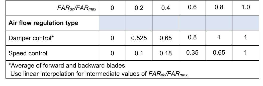
133.In addition to affecting the fresh air load (i.e. energy to heat and cool the fresh air), demand control of ventilation can also affect the auxiliary energy. Where there is demand control of ventilation, the auxiliary energy calculation will use FARmax pro- rated by a value obtained from Table 15a, depending on the type of control for air regulation and the ratio of modified fresh air rate to maximum fresh air rate (i.e. FARdc /FARmax).
Table 15a: Proportion of maximum fan power in case of demand control of ventilation
Shell buildings
#Source page 36
134.In the context of application for building warrant, a shell building is defined as a building where elements of the fixed building services are absent and further installation work will be required before the building can be occupied and used. A staged building warrant, covering both shell and subsequent fit-out work, is not subject to the following process.
135.Shell buildings are subject to the compliance check against the TER & TDER under the conditions specified in clause 6.1.10 of Section 6.
136.Assessment under standard 6.1 is required both for the shell building warrant and also for the subsequent fit-out works, via the imposition of a continuing requirement in this respect on the shell warrant. Regardless of whether or not a building warrant is required for fit-out work, this continuing requirement must be discharged before the building can be occupied (refer to clause 5.6 of the BSD Procedural Handbook30). Assessment of the fit-out work should be made using the category ‘other buildings’ under ‘S6 type of building’.
137.Assessment of the shell building should show that the building, as completed, could meet standard 6.1. This is done by providing a completed service specification for each zone, identifying which services are to be installed as part to shell works and which are assumed to form part of a subsequent fit-out. Assumed (uninstalled) services should be defined at zone level by identifying whether the zone is a fit-out area (approved software tools must allow for this identification). iSBEM enables this by providing a tick-box within the Geometry/ Zones tab if ‘shell building’ is selected under ‘S6 type of building’.
138.Energy associated to HVAC, lighting and HW systems serving 'fit-out' zones will be accounted for as normal in the calculation, which will assume that fit-out services are fully operational, designated temperatures are maintained, lighting and hot water provided in all zones. That means the boundary conditions between zones are unaffected. The calculation for the Notional building is unaffected by this process.
139.Where these procedures apply to compliance with standard 6.1, EPC generation required under standard 6.9 should be deferred until the fit-out stage of such a building by inclusion of that provision in the continuing requirement. This deferral is on the basis that a shell building is incomplete and cannot be occupied and will ensure that the lodged EPC represents the building as fitted out.
Modular and portable buildings
#Source page 37
140.For modular and portable buildings with an intended life on site of less than five years, the TER & TPER must be adjusted as described in Annex 6.B of Section 6.
141.Annex 6.B also specifies the fabric limiting standards for these types of buildings. Approved tools must allow users to specify the necessary information to apply such adjustments. Users are expected to follow guidance in Section 6 to correctly populate these fields.
Extensions to the insulation envelope
142.Large extensions (extensions to non-domestic buildings where the extension will have an area which is both greater than 100 square metres and greater than 25% of the area of the existing building) must demonstrate compliance with the carbon dioxide emissions standard 6.1.
143.For all other extensions to the insulation envelope, the new building fabric should be designed to achieve the elemental performance set out in guidance clause 6.2.11 of Section 6. Alternatively, as noted in that clause, it is possible to assess the extension in isolation from the existing building or, alternatively, assess the entire building as extended using SBEM. Both these approaches are compatible with iSBEM.
Building Emission Rate (BER) and Building Delivered Energy Rate (BDER)
144.The BER is the CO 2 emission rate of the Actual building reported in kg.CO 2e per square metre of the building’s total floor area. Similarly, the BDER is the delivered energy rate of the Actual building reported in kWh/m². Standard 6.1 only require the calculation of an emission target where a new building is heated or cooled, in whole or in part, by a direct emissions heating system. Where such a system is not present, only the delivered energy target must be met. Calculated emissions are still reported for the Actual building. Primary energy (PE) totals should be calculated but are reported as EPC output, not for compliance with Standard 6.1.
145.The following approach is applied when calculating the two building rates for the Actual building for building regulations compliance purposes only. Noting that this has the effect of excluding any predicted export component of on-site generation from both the emissions and the delivered energy calculation.
a.Calculate the total monthly demand for energy from all regulated sources within the building which consume electricity.
b.The calculated monthly total for equipment load within SBEM is assigned to represent ‘plug-in’ electrical load.
c.Calculate the monthly total for on-site generation, for PV and separately for any other source. Determine the sum of all sources.
CHECKING SOLAR GAINS
#Source page 38
d.Determine total ‘useful generation’, which is the lesser of (a+b) or c. Note: If c is greater than (a+b), the software tool should notify this to the user so that they are aware that the calculated useful generation capacity is exceeded.
e.Calculate monthly emissions and PE for electrical demand (a) only, applying the factors from Table 19b.
f.Calculate monthly emissions and PE for useful electrical generation only (d), applying the relevant factors for PV or another source (Tables 19b & 19c). Noting that where generation includes other than by PV, this should be counted before PV (e.g. prioritise the ‘same’ factors).
g.Calculate the monthly emissions and PE for energy totals from all other fuels consumed using, applying the factors from Table 19a.
h.Calculate the net monthly total for emissions and PE as, in both cases, e–f+g.
i.Repeat the above process, without the application of emission factors, to calculate the net monthly totals for the Actual Building Delivered Energy Rate.
146.Noting that, as with the Notional Building, for building regulations compliance, this has the effect of excluding any predicted export component of on-site generation from both the emissions and the PE calculation. The intent of this is to avoid over- specification of generation as part of building solutions where this does not contribute to the reduction of the delivered energy total for the building.
147.The annual sum of the net monthly totals for emissions and delivered energy, once divided by the total floor area of the building are presented as the Building Emission Rate and the Building Delivered Energy Rate. Compliance is achieved where neither the Building Emission Rate nor the Building Delivered Energy Rate exceed their respective Target rating, the Target Emission Rate and the Target Delivered Energy Rate.
148.A separate calculation, using the Actual building specification, is undertaken for EPC purposes to produce a Building Energy Performance Rating (emissions, Current and Potential), Primary Energy Indicator and to report Approximate Energy Use. This process differs from the building regulations compliance calculation as it does not exclude the export component of any on-site generation present. The EPC outputs calculation approach is described in paragraphs 169-172.
CHECKING SOLAR GAINS
149.This section describes how solar gains should be checked in the Actual building.
150.The solar gain check will include any zone in the Actual building that is either receiving cooling or has an activity that is flagged in the NCM Activity database as being an occupied space for which the solar gain check is applicable. Whether or not the solar gain check is applicable to the activity is determined in the “activity” table
Page 39
#Source page 39
•from the NCM Activity database in the “SOLAR_GAIN_CHECK” field (0 for activity with no solar gain check, and 1 for activity with solar gain check).
151.The solar gain in the Actual building is calculated at the point of absorption into the internal surfaces of each zone and includes the solar gain absorbed in the glazing and/or blinds, which subsequently enters the space via conduction/ radiation/ convection.
152.The contribution of solar gain from display windows will be checked for zones where the solar gain check applies.
153.The solar gain check is based on the solar gains through the benchmark glazing types described in Table 16, and selected according to paragraph 157, aggregated over the period from April to September, and using the same CIBSE TRY weather data used for the emissions and energy calculations (standard 6.1).
| Table 16: General description of benchmark glazing for setting solar gain limit | ||
|---|---|---|
| Benchmark glazing type | Description | Glazing dimensions/ area |
| 1 | Vertical glazing facing east with 10% frame factor and g-value of 0.48 | Height of 1m and width equal to the total exposed facade* width of the zone being checked |
| 2 | Horizontal glazing with 25% frame factor and g-value of 0.48 | Area equal to 10% of either the projected floor area or the exposed roof area** (whichever is greater) |
| 3 | Horizontal glazing with 15% frame factor and g-value of 0.42 | Area equal to 10% of either the projected floor area or the exposed roof area** (whichever is greater) |
| * The exposed facade width should take into account opaque/ translucent wall elements, as well as external doors, external windows, and curtain walling systems. ** The exposed roof area is determined from inside the space looking out. |
154.The treatment of solar gains entering a space will vary between DSM software so for DSM software, it is necessary to define a standard test-space for each benchmark glazing type (refer to Figures 1 and 2) that meets the requirements of Table 16. This allows the pre-calculation of the benchmark aggregated solar gain as a function of facade length and exposed roof area (i.e. kWh/m and kWh/m² respectively). This means that each DSM will have 3 values for benchmark aggregated solar flux for each CIBSE TRY weather data set.
155.The standard test spaces will have solar absorptance of 0.5 for all internal surfaces. The external ground reflectance should be 0.2. The glazing should use the appropriate glass data provided in Table 17 and Table 18 (where Tsolar is the direct solar transmittance, Tvisible is the direct visible light transmittance, Rsolar is the solar reflectance, and Rvisible is the visible light reflectance. The subscripts 1 and 2 refer to the outer and inner surfaces of each pane of glass respectively).
Page 40
#Source page 40
156.As part of validation, DSM software must to declare the benchmark aggregated solar flux values. Once approved, the declared benchmark aggregated solar flux values cannot be changed unless re-validation is carried out.
157.The solar gain limit is calculated and checked on a zone-by-zone basis in the Actual building, using the following methods:
a.For zones with side-lit or unlit activities:
•For each zone with exposed facade area greater than zero, the limiting solar gain will be the aggregated solar flux for benchmark glazing type 1 multiplied by the exposed facade length.
•For each zone with zero exposed facade area (i.e. an internal zone that receives second hand solar gains), the limiting solar gain will be the aggregated solar flux for benchmark glazing type 2 multiplied by either the projected floor area or the exposed roof area (whichever is greater).
b. For zones with top-lit activities:
•For each zone where the height31 is less than 6 m, the solar gain limit will be the aggregated solar flux for benchmark glazing type 2 multiplied by either the projected floor area or the exposed roof area (whichever is greater).
•For each zone where the height31 is greater than or equal to 6 m, the solar gain limit will be the aggregated solar flux for benchmark glazing type 3 multiplied by either the projected floor area or the exposed roof area (whichever is greater).
158.The total solar gain aggregated over the period from April to September for each zone in the Actual building where the solar gain check applies, will have to be less than or equal to the limiting solar gain calculated based on the benchmark glazing types. For DSM software, the total solar gain should include external solar gain from all orientations and inclinations as well as any “second hand” solar gain from adjacent zones (i.e. via internal glazing/ holes/ virtual partitions).
159.The aggregated solar gain should not include the conduction gains via window frames or solar gains through opaque envelopment elements (e.g. sol-air temperature gains through the roof/ walls).
| Table 17: Glass properties to achieve g-value of 0.48 | |||||||||
|---|---|---|---|---|---|---|---|---|---|
| Thickness | Tsolar | Rsolar1 | Rsolar2 | Tvisible | Rvisible1 | Rvisible2 | Emissivity 1 | Emissivity 2 | |
| Outer pane | 6 mm | 0.489 | 0.319 | 0.217 | 0.791 | 0.045 | 0.071 | 0.045 | 0.302 |
| Cavity | 16 mm | Argon gas fill | |||||||
| Inner pane | 6 mm | 0.895 | 0.079 | 0.079 | 0.908 | 0.082 | 0.082 | 0.840 | 0.840 |
Figure 1 Isometric view of standard test-space for benchmark glazing type 1
#Source page 41
| Table 18: Glass properties to achieve g-value of 0.42 | |||||||||
|---|---|---|---|---|---|---|---|---|---|
| Thickness | Tsolar | Rsolar1 | Rsolar2 | Tvisible | Rvisible1 | Rvisible2 | Emissivity 1 | Emissivity 2 | |
| Outer pane | 6 mm | 0.430 | 0.269 | 0.298 | 0.664 | 0.169 | 0.070 | 0.840 | 0.072 |
| Cavity | 16 mm | Argon gas fill | |||||||
| Inner pane | 6 mm | 0.895 | 0.079 | 0.079 | 0.908 | 0.082 | 0.082 | 0.840 | 0.840 |
Figure 1 Isometric view of standard test-space for benchmark glazing type 1
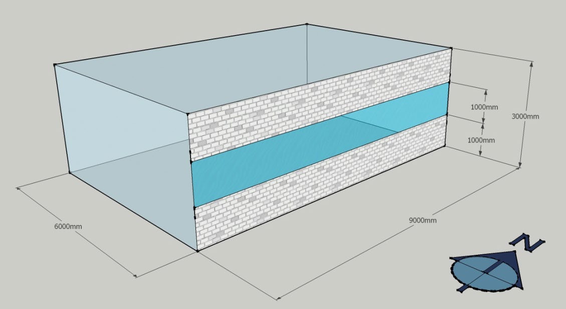
Figure 2 Isometric view of standard test-space for benchmark glazing type 2 & 3
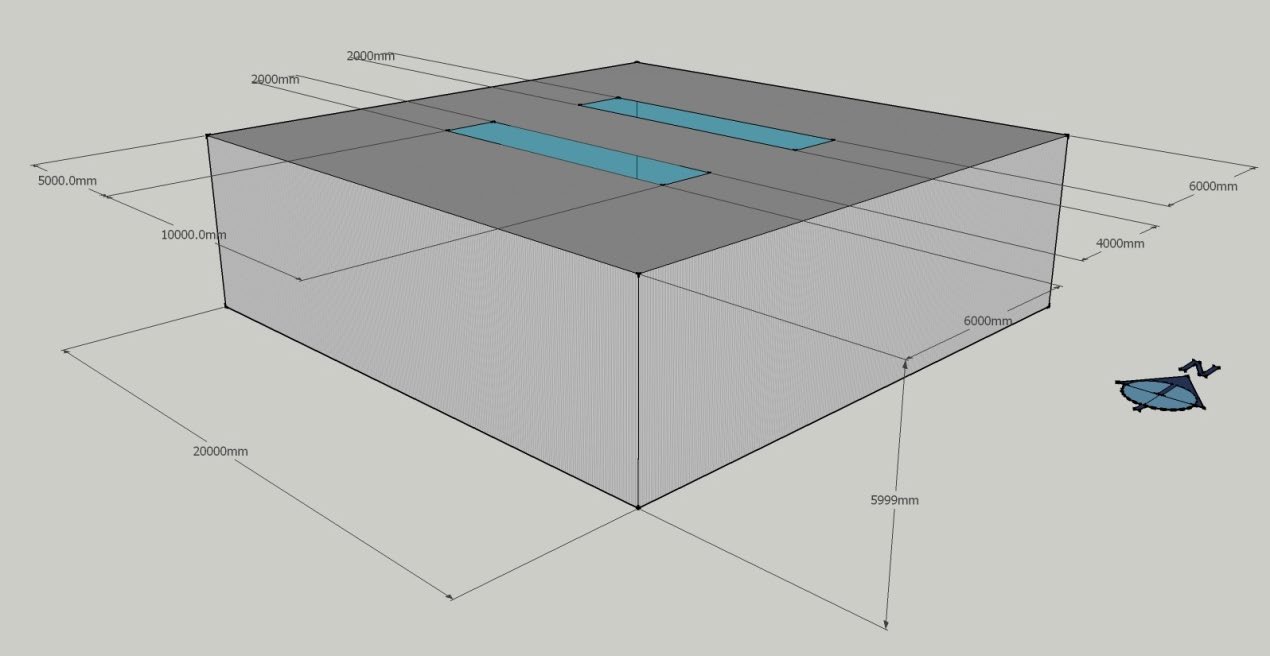
ENERGY PERFORMANCE CERTIFICATES (EPCS)
160.Further review of EPC practice during 2022/23, in support of our Heat in Buildings Strategy, will determine whether and when aspects of the proposed changes implemented for building regulations compliance purposes are implemented in EPC calculations. The following guidance is unchanged from 2015, with the exception that,
Page 42
#Source page 42
•following changes to the building regulations compliance calculation, the difference in calculation process for EPC purposes is set out in paragraphs 169-172.
161.Energy Performance Certificates (EPCs) provide prospective buyers/ tenants with information about the energy performance of a building and practical advice on improving performance. Cost effective recommendations for improving the energy performance of the building detailed on the certificate must meet the Scottish building regulations, be specific to the individual building and be technically feasible. The EPC displays the “rating” of a building in the form of the approximate annual Building CO 2 Emission Rate (BER) in kg per m² of floor area per year, rated on a seven band scale (see guidance to standard 6.9 in Section 6).
162.While an EPC is not required for permanently unconditioned buildings (i.e. buildings which do not use energy to condition the indoor climate and are expected to remain this way), it is possible to voluntarily produce EPCs for unconditioned buildings. Permanently unconditioned buildings are different to those which are currently unconditioned but are intended to be conditioned prior to occupation, and which should be modelled as per the guidance on shell and fit out buildings in Section 6. Further guidance on EPCs is provided in the BSD website32.
163.The EPC ‘A to G’ scale and energy labels present the calculated value of the BER are displayed on a seven band graphical scale where a letter band corresponding to a range of emissions ratings, with “A+ (net zero carbon or better)” being the most efficient (followed by “A”) and “G” being the least efficient.
The EPC Rating Scale
BER ≤ 0.0 → A+ (net zero carbon or better)
0.0< BER ≤ 15.0 → A
15.0< BER ≤ 30.0 → B
30.0< BER ≤ 45.0 → C
45.0< BER ≤ 60.0 → D
60.0< BER ≤ 80.0 → E
80.0< BER ≤ 100.0 → F
100.0< BER → G
Other reference values
#Source page 43
164.The EPC is accompanied by a “Recommendations Report”, which contains a list of NCM recommendations, edited and added to by the assessor, for the improvement of the energy performance of the building and their respective potential impact on the CO 2 emission rate of the building. The recommendations are grouped into the following sub-sections in the report: short payback (up to 15 recommendations), medium payback (up to 10 recommendations), long payback (up to 5 recommendations), and other recommendations created by the assessor (up to 10 recommendations).
165.The EPC itself displays up to six recommendations, beginning with the short payback (i.e. three years or less) NCM recommendations. If there are user-defined or user- edited recommendations, then the EPC displays the top 3 NCM cost effective recommendations with a payback period of three years or less and up to 3 user recommendations with the shortest payback.
166.The impact of the recommendations on the CO 2 emission rate of the building and their estimated payback33 is assessed based on the energy performance of the Actual and Notional buildings.
Other reference values
167.In addition to the building rating, the EPC displays two reference values as follows:
a. The potential rating of the Actual building had it been built to building regulations standards current at the date of issue of the EPC.
b. The potential rating of the Actual building if recommended cost-effective improvements were applied. Assessors can use the software tool to determine that improved rating by creating a scenario within the building model, in which to implement their selected cost-effective recommendations and running the calculation again. The value of the improved rating can then be inserted into the software tool and will be recorded as part of the XML output used to lodge data to the EPC register.
168.The EPC also displays other information such as, the approximate annual energy use of the building, in kWh/m² of floor area, the main heating fuel, the electricity source, the ventilation strategy and the main renewable energy source in the building (if applicable) and the calculation tool used to produce the assessment.
Calculation of energy and emissions outputs for Energy Performance Certificates.
169.The calculation of energy totals for EPCs and uses other than compliance with building regulations differs in that the export component of on-site generation is still
Page 44
#Source page 44
•included in totals. The following paragraphs set out the difference in calculation approach for the EPC outputs.
170.The following approach is applied when calculating totals for the Actual building other than for building regulations compliance purposes. This calculates outputs which continue to report the full component of any on-site generation present. The example shown is for building emissions.
a.Calculate the monthly electrical energy used by the Actual building irrespective of source of supply. Multiply that energy use by the monthly CO 2 emission factors for grid-supplied electricity from Table 19b.
b.Calculate the annual energy associated with any other fuels used in the Actual building and multiply the energy use by the respective CO 2 emission factors for the fuels from Table 19a (or from the process set out in paragraphs 194 -196 for district heating networks).
c.Calculate the monthly electricity generated by any on-site PV systems, multiply that by the monthly CO2 emission factors for grid-displaced electricity by PV from Table 19c (irrespective of the proportion of electricity that is used on site and how much is exported).
d.Calculate the monthly electricity generated by any on-site systems other than PV, e.g.for wind or CHP generators, multiply that by the monthly electricity CO 2 emission factors from Table 19b (irrespective of the proportion of electricity that is used on site and how much is exported).
e.The net figure of ‘a plus b minus c minus d’ above is the monthly CO 2 emissions for the Actual Building Energy Performance Rating. This is calculated for both the current and potential Rating.
f.Repeat the above process, with the application of PE factors, to calculate the net monthly totals for the Actual building Primary Energy Indicator.
g.Repeat the above process, without the application of emission factors, to calculate the net monthly totals for the Actual building Approximate Energy Use.
171.The annual sum of the net monthly totals for each of the calculations once divided by the total floor area of the building are presented on the EPC as:
•the Building Energy Performance Rating (emissions, Current and Potential),
•the Primary Energy Indicator and
•the Approximate Energy Use.
172.The approach set out in paragraph 170 steps (a) to (e) is also applied using the notional building specification instead of the actual building specification to illustrate what the Building Energy Performance Rating would be if an existing building was constructed to the current notional building specification. This is presented as the Newbuild Benchmark rating on the EPC.
APPENDIX A - INPUT DATA TO APPROVED TOOLS
#Source page 45
173.This section of the guide describes generally applicable approaches to data input and modelling strategies, and it applies equally to Section 6 compliance and EPCs and also to the modelling of the Actual and Notional buildings.
Defining internal gains and environmental conditions
174.In order to facilitate estimating energy performance on a consistent basis, a key part of the NCM is an Activity database that defines the activities in various types of space in different classes of building34. One of these standard activities must be assigned to each space in the building35.
175.A 2021 version of the NCM Activity database has been updated from 2013/15 to accompany the 2022 version of the NCM Modelling Guide.
176.The NCM Activity Database provides standard occupancy, temperature set-points, outdoor air rates and heat gain profiles for each type of space in the building so that buildings in Scotland with the same mix of activities will differ only in terms of their geometry, construction, and building services. Thus, it is possible for the Section 6 compliance checks and EPCs to compare buildings on the basis of their intrinsic potential performance, regardless of how they may actually be used in practice.
177.The fields of information in the database are as follows:
a.Occupancy times and density; total metabolic rate and percentage which is latent (water vapour);
b.Set-point temperature and humidity in heating and cooling modes; DSM software will use air temperature as the basis for temperature set-points for the Actual and Notional buildings;
c.Set-back conditions for unoccupied periods;
d.Sensible and latent heat gain from other sources;
e.Outside air requirement;
f.Level of illuminance for general lighting and the power density for display lighting;
g.Hot water demand;
h.Type of space for glazing, lighting, and ventilation classification within Section 6 compliance;
i.A marker indicating whether the activity requires high efficiency filtration, thereby justifying an increased SFP allowance for that space to account for the increased pressure drop.
Constructions
#Source page 46
178.If there is not an activity in the Activity Database that reasonably matches the intended use of a space, then this could be raised with the database managers (see NCM website36 for details), and an appropriate new activity may be proposed. This will be subject to peer review prior to formal acceptance into the database. Note that it is NOT acceptable for users to define and use their own activities. Consistent and auditable activity schedules are an important element of the compliance and certification processes, and so only approved activity definitions can be used for these purposes37. If a special use space is present in the Actual building, and no appropriate activity is available in the database, it is accepted that time pressures may preclude waiting for the specific activity definition to be developed, peer reviewed, and approved. In such situations, the assessor must use their technical expertise or seek guidance from appropriate sources in order to select the closest match from the approved database. Because compliance and certification are both based on the performance of the Actual building in comparison to that of a Notional building, the impact of this approximation should be minimised.
Constructions
179.The thermal performance of construction elements must take account of thermal bridges:
a.Repeating thermal bridges must be included in the calculated plane element U- value as detailed in BR44338. Simulation tools that use layer by layer definitions will need to adjust thicknesses of insulation layers to achieve the U-value that accounts for the repeating thermal bridges.
b.Non-repeating thermal bridge heat losses must be allowed for by a method that satisfies BS EN ISO 14683 or by adding a specified percentage increase to the standard area-weighted average U-values (see paragraphs 43 & 106). Whichever method is applied must be applied to both Notional and Actual building calculations
180.Available on the NCM website are databases of calculated U-values, etc. (NCM Construction database and NCM Glazing database), and for consistency, all implementations of the NCM should preferably use these databases. It is accepted that a required construction may not always exist in the NCM database. In such cases, alternative sources of data may be used, but the person submitting for Section 6 compliance must declare this and demonstrate how the values were derived.
181.When using the software tool to generate an EPC for an existing building, the performance parameters for some constructions may not be known. In such
Weather location
#Source page 47
•situations, the parameters must be inferred based on the data provided in the NCM Construction database. This is an important aspect of ensuring consistency in energy rating calculations, and so all software tools must adopt these procedures. This will be checked as part of the approval process.
Weather location
182.In order to calculate the reaction of the building and systems to the variable loads imposed by the external environment, the NCM needs an input of weather data. A standard weather set has been adopted for Scotland which must be used39.
Zoning rules
183.The way a building is sub-divided into zones will influence the predictions of energy performance. Therefore, this guide defines zoning rules that must be applied when assessing a building for the purposes of Section 6 compliance or producing the Energy Performance Certificate. The following procedure defines the approach to zoning for HVAC and lighting that must be followed.
184.The zoning arrangement must mimic the control strategy in the Actual building, and the same zoning arrangement must then be applied in the Notional building. In the Actual building, zoning is defined by the extent of the control systems that modulate the output of the HVAC and lighting systems. Mapping the physical control zones into modelling zones should be the starting point for the zoning procedure. Any further adjustment to the zoning should only be:
a.As specified in the following general guidance (see paragraphs 185 to 190); or
b.Where specific limitations are imposed by the modelling tool that is being used (e.g. where a tool only permits each modelled zone to comprise one thermal zone and one lighting zone).
Zone types
185.A thermal zone is an area that:
a.Has the same heating and cooling set-points; and
b.The same ventilation provisions; and
c.Has the same plant operating times; and
d.Has the same set-back conditions; and
e.Is served by the same type(s) of terminal device; and
Combining adjoining thermal zones
#Source page 48
f.Is served by the same primary plant; and
g.Where the output of each type of terminal device is controlled in a similar manner.
186.A lighting zone is an area that:
a.Has the same lighting requirement (levels and duration); and
b.Is served by the same type(s) of lamp/ luminaire combination; and
c.Where the output of the lighting system is controlled in a similar manner; and
d.Has similar access to daylight, i.e. the zone is bounded with fenestration having similar glazing ratio, light transmittance, and orientation. This means that where benefit is being taken of daylight-linked controls (manual or automatic), a given lighting zone must not extend beyond ~6m from the perimeter.
187.For the purposes of modelling, a thermal zone can contain multiple lighting zones (e.g. daylight control at the perimeter with manual switching in the interior), but a lighting zone cannot extend across the boundary of a thermal zone. If this does occur in the Actual building, the relevant lighting zone must be subdivided into multiple smaller zones. The boundaries of these smaller zones are defined by the boundaries of the thermal zones.
Combining adjoining thermal zones
188.Adjoining thermal zones (horizontally or vertically40) may be combined into a single larger zone provided that:
a.The zones are all the same in terms of the characteristics defined in paragraph 185 above; and
b.The zones all have the same combination of activities inside them; and
c.The zones all have the same combination of lighting zones within them; and
d.The zones all have the same exposure to the external environment in terms of glazing percentages, glazing types, and orientation.
189.Where adjoining thermal zones are combined, then the partitions that separate the physical spaces must be included in the thermal zone in order to properly represent the thermal storage impact.
190.It is recommended that users make full use of features such as, the ‘multiplier’ function and merging of all contiguous similar areas, in order to generally avoid creating more than 100-150 zones in SBEM.
Fuel emission and primary energy factors
#Source page 49
191.Emissions factors and Primary Energy factors41 for fuels are defined below.
| Table 19a: Factors for non-domestic buildings | ||||||||||||
|---|---|---|---|---|---|---|---|---|---|---|---|---|
| Fuel type | Emission Factor kgCO 2/ kWh | Primary Energy Factor kWh/ kWh | ||||||||||
| Natural gas | 0.210 | 1.126 | ||||||||||
| LPG | 0.241 | 1.141 | ||||||||||
| Biogas | 0.024 | 1.286 | ||||||||||
| Fuel oil | 0.319 | 1.18 | ||||||||||
| Coal | 0.375 | 1.064 | ||||||||||
| Anthracite | 0.395 | 1.064 | ||||||||||
| Manufactured smokeless fuel (inc. Coke) | 0.366 | 1.261 | ||||||||||
| Dual fuel (mineral + wood) | 0.087 | 1.049 | ||||||||||
| Biomass | 0.029 | 1.037 | ||||||||||
| Grid supplied electricity | See below | See below | ||||||||||
| Grid displaced electricity | See below | See below | ||||||||||
| Waste heat⁴² | 0.015 | 1.063 | ||||||||||
| District heat networks | See below | See below | ||||||||||
| Table 19b: Factors for grid-supplied electricity and grid-displaced electricity except that generated by PV systems | ||||||||||||
| Month | Jan | Feb | Mar | Apr | May | Jun | Jul | Aug | Sep | Oct | Nov | Dec |
| Kg.CO 2/kWh | 0.163 | 0.160 | 0.153 | 0.143 | 0.132 | 0.120 | 0.111 | 0.112 | 0.122 | 0.136 | 0.151 | 0.163 |
| kWhpe/kWh | 1.602 | 1.593 | 1.568 | 1.530 | 1.487 | 1.441 | 1.410 | 1.413 | 1.449 | 1.504 | 1.558 | 1.604 |
| Table 19c: Factors for grid-displaced electricity from PV systems | ||||||||||||
| Month | Jan | Feb | Mar | Apr | May | Jun | Jul | Aug | Sep | Oct | Nov | Dec |
| Kg.CO 2/kWh | 0.196 | 0.190 | 0.175 | 0.153 | 0.129 | 0.106 | 0.092 | 0.093 | 0.110 | 0.138 | 0.169 | 0.197 |
| kWhpe/kWh | 1.715 | 1.697 | 1.645 | 1.567 | 1.478 | 1.389 | 1.330 | 1.336 | 1.405 | 1.513 | 1.623 | 1.718 |
192.Emissions and primary energy conversion factors for heat networks should be calculated to take account of the annual average performance of the whole system, including all distribution and heat generating characteristics and should be provided for the connecting network, from an assured source, by the network provider. For network
Page 50
#Source page 50
•heat generation sources, the values in Table 19d should be used and apportioned according for the sources contributing to the network.
193.Whilst these factors are used to calculate emissions and primary energy totals for the Actual building, they are no longer applied as part of the process of demonstrating compliance with standard 6.1 for new buildings where all heating demand is met from district heating.
| Table 19d: Factors for heat supplied from district heat networks | ||
| Fuel type | kgCO 2/kWh | kWh PE/kWh |
| Heat from boilers that use mains gas | 0.21 | 1.13 |
| Heat from boilers that use LPG | 0.241 | 1.141 |
| Heat from boilers that use oil (assumes gas oil) | 0.335 | 1.18 |
| Heat from boilers that can use mineral oil or biodiesel | 0.335 | 1.18 |
| Heat from boilers that use HVO from used cooking oil | 0.036 | 1.18 |
| Heat from boilers that use FAME from animal/vegetable oils ¹ | 0.018 | 1.18 |
| Heat from boilers that use B30D ² | 0.269 | 1.09 |
| Heat from boilers that use coal | 0.375 | 1.064 |
| Heat from electric heat pump | 0.136 | 1.501 |
| Heat recovered from waste combustion | 0.015 ³ | 0.063 ³ |
| Heat from boilers that use biomass | 0.029 | 1.037 |
| Heat from boilers that use biogas (landfill or sewage gas) | 0.024 | 1.286 |
| Heat recovered from power stations | 0.015 ³ | 0.063 ³ |
| High grade heat recovered from process | 0.011 | 0.051 |
| Low grade heat recovered from process | 0.136 ⁴ | 1.501 ⁴ |
| Heat recovered from geothermal or other natural processes | 0.011 | 0.051 |
| Heat from CHP | as above according to fuel used | as above according to fuel used |
| Electricity for pumping in distribution network | 0.136 | 1.501 |
| Electricity generated by new CHP, export only | 0.394 | 2.345 |
| Electricity generated by new CHP, flexible operation | 0.42 | 2.369 |
| Electricity generated by new CHP, standard | 0.311 | 2.107 |
| Electricity generated by existing CHP (2015+), export only ⁵ | 0.394 | 2.345 |
| Electricity generated by existing CHP (2015+), flexible operation ⁶ | 0.42 | 2.369 |
| Electricity generated by existing CHP (2015+), standard ⁷ | 0.348 | 2.149 |
| Electricity generated by existing CHP (pre-2015), export only ⁵ | 0.394 | 2.345 |
| Electricity generated by existing CHP (pre-2015), flexible operation ⁶ | 0.42 | 2.369 |
| Electricity generated by existing CHP (pre-2015), standard ⁷ | 0.374 | 2.23 |
Notes:
1.For appliances that specifically use bio-liquid FAME to BS EN 14214 certified as wholly derived from waste animal fats/used cooking oil.
2.For appliances that specifically use a blend of 30% bio-liquid FAME, and 70% kerosene (B30K) or 70% gas oil (B30D).
Calculating emission and primary energy conversion factors for heat networks
#Source page 51
3.Takes account of the reduction in electricity generation that occurs where heat is produced at a high enough temperature to supply a heat network.
4.Figure assigned to energy used by heat pump to boost temperature.
5.‘Export only’ fuel factors should be used where a gas CHP exports all of its power to the grid (except for energy centre parasitic loads).
6.‘Flexible operation’ fuel factors should be used when a gas CHP unit runs only when the marginal generating plant on the grid is high carbon (i.e. gas CCGT).
7.‘Standard’ fuel factors should be used for all other operating regimes of gas CHP plants.
Calculating emission and primary energy conversion factors for heat networks
194.Both building emissions and building primary energy totals are reported on the non- Domestic Energy Performance Certificate. Where thermal energy is supplied from a heat network, the required emission and primary energy conversion factors for that network should be determined by considering the details of the scheme, as follows:
•The emission factor and primary energy factor for heat sources connected to the network should be taken from the ‘heat network’ specific factors for heat source types from Table 19d.
•Calculations should take account of the annual average performance of the whole system, including the distribution circuits, all heat generating plants, combined heat and power (CHP), and any waste heat recovery or heat dumping.
•The electricity generated by any combined heat and power (CHP) or tri- generation scheme should always be credited using the appropriate emission and primary energy ‘heat network’ specific factors from Table 19d.
•Emissions and primary energy associated with the thermal energy streams of a tri-generation scheme should be attributed in proportion to the output energy streams.
•To enable application of the correct emission and primary energy conversion factors to the building, the person undertaking the calculation should be provided with a report, signed by a suitably qualified person, detailing how the emission factors and primary energy factors for the network have been derived.
195.The primary energy conversion factor for the heat output should be taken as:
1/H x (F x PEF – E x PE E ) where:
H is the useful heat (excluding heat rejected) in kWh
F is the fuel input in kWh
PE F is the primary energy factor for the input fuel in kWhPE/kWh
E is the electricity production from the scheme in kWh
HVAC
#Source page 52
PE E is the primary energy factor for district heat CHP generated electricity in kWhPE /kWh.
196.The emission conversion factor for the heat output should be taken as:
1/H x (F x CO 2F – E x CO 2E ) where:
H is the useful heat (excluding heat rejected) in kWh
F is the fuel input in kWh
CO 2F is the emission factor for the input fuel in kgCO 2/kWh
E is the electricity production from the scheme in kWh
CO 2E is the emission factor for district heat CHP generated electricity in kgCO 2/kWh.
HVAC
197.For the Actual building, DSMs may represent HVAC systems explicitly but will be required to report system seasonal performance parameters as an aid to checking, see paragraph 7(c).
198.For DSM software that model HVAC with temperature control bands, the activity cooling/ heating set-points from the NCM Activity database should be used as the mid-band point, and the control band should be ±0.5 K or less.
Lighting
199.Lighting calculations for ‘as designed’ compliance checks should assume a space maintenance factor of 0.8, which corresponds to a clean space that is maintained every 3 years (EN 12464).
200.For Section 6 compliance, the lighting power density for activities such as storage warehouses and retail spaces, which have racking/ shelving, should be adjusted to ignore these elements (as the Notional building does not take these into account).
201.For Section 6 compliance, the lighting power density for activities which require special light fittings (e.g. intrinsically safe/ anti-ligature luminaires), or where full spectrum daylight lamps are required (e.g. for medical purposes), should be adjusted to compensate for the de-rated output so that there is a fair comparison against the Notional building. Such adjustments need to be clearly documented and justified to the local authority verifier.
Adjustment factors
202.In order to eliminate discrepancies between approved calculation tools with regards to the stage at which to apply adjustment factors for enhanced management and control
Measurement and other conventions
#Source page 53
•features from Section 6, clause 6.1.7, the following approach should be followed if adjustments are applicable:
a.Apply the adjustment factor due to power factor correction on the CO2 emissions and energy consumption which are attributed to grid-supplied electricity in the building.
b.Apply the adjustment factor due to automatic monitoring and targeting (M&T) with alarms for out-of-range values to the energy consumption attributed to the lighting or HVAC system with the M&T feature.
Measurement and other conventions
203.In order to provide consistency of application, standard measurement conventions must be used. These apply to both DSMs and third party software interfaces to SBEM, although some parameters may only relate to the latter. These conventions are specified in Table 20 below:
| Table 20: Measurement and other conventions | |
|---|---|
| Parameter | Definition |
| Zone Area | Floor area of zone calculated using the internal horizontal dimensions between the internal surfaces of the external zone walls and half-way through the thickness of the internal zone walls. Used to multiply area- related parameters in databases. NB: If the zone has any virtual boundaries, e.g. no walls in certain orientations, the area of the zone is that delimited by the ‘line’ defining the virtual boundary. |
| Envelope Area | Area of vertical envelopes (walls) = h × w, where: h = floor to floor height, i.e. including floor void, ceiling void, and floor slab. For top floors, h is the height from the floor to the average height of the structural ceiling. w = horizontal dimension of wall. Limits for that horizontal dimension are defined by type of adjacent walls. If the adjacent wall is external, the limit will be the internal side of the adjacent wall. If the adjacent wall is internal, the limit will be half-way through its thickness. NB: Areas of floors, ceilings, and flat roofs are calculated in the same manner as the zone area. Area for an exposed pitched roof (i.e. without an internal horizontal ceiling) will be the inner pitched surface area of the roof. |
| Window Area | Area of the structural opening in the wall/roof; the area, therefore, includes the area of glass + frame. |
| HWS Dead-leg Length | Length of the draw-off pipe to the outlet in the space (only used for zones where the water is drawn off). Used to determine the additional volume of water to be heated because the cold water in the dead-leg has to be drawn off before hot water is obtained. Assumes that HWS |
APPENDIX B – EPBD RECAST AND 2018 AMENDMENT
#Source page 54
Table 20: Measurement and other conventions
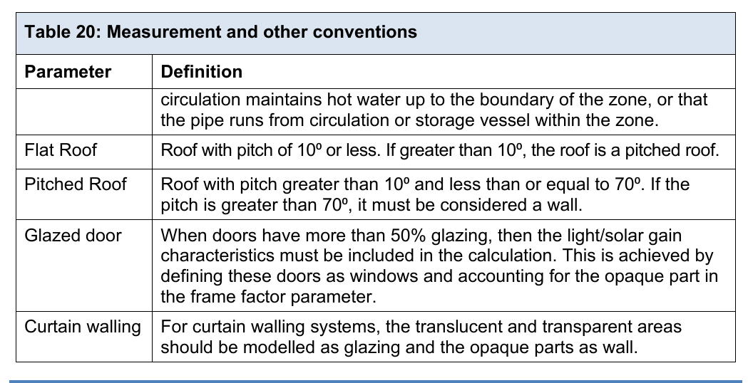
APPENDIX B – EPBD RECAST AND 2018 AMENDMENT
204.This section describes the added requirements of the amended Energy Performance of Buildings Directive (2018) retained and presented in the calculation methodology and output reports.
Primary energy consumption
205.An Actual building primary energy indicator is calculated and reported, based on the energy consumption for each fuel and the corresponding primary energy factors, as defined in Tables 19a to 19c and those calculated for a district heating network as set out in paragraphs 194 -196. This will be reported in the SBEM Specification Information summary.
High-efficiency alternative energy systems
206.Software tools will include additional questions for the user to confirm that the designers have considered in the new building design, the technical, environmental and economic feasibility of ‘high-efficiency alternative systems’, as noted in the introduction to standard 6.1 and in Annex 6.C of the Non-domestic Technical Handbook and to confirm that there is documentary evidence of the feasibility assessment. Software tools should also ask if designers have included any such systems in the proposed design solution. The answers to these questions will be reported in the SBEM Specification Information summary.
APPENDIX C – CONSTRUCTION FOR 2022 NOTIONAL BUILDING
#Source page 55
207.This section includes screen grabs from the BRE U-value calculator that show the construction details used as the basis for the data for thermal capacity values in Table 2. These construction details are for use by DSM software to account for the effect of thermal capacity.
208.DSM software generally use less sophisticated methods for calculating the U-value of constructions (i.e., they do not take account of repeating thermal bridges due to fixings, etc.). Therefore, where appropriate, the thickness of the insulation layer should be adjusted to achieve the same U-value as specified in Table 1.
209.Roof construction details - 2022 Notional building (not involving metal cladding)
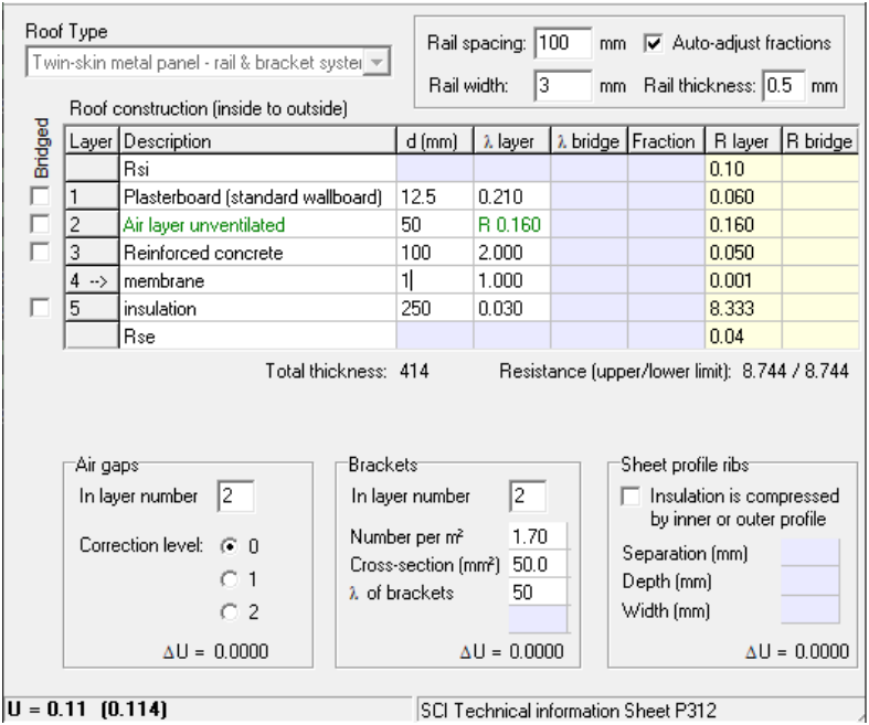
Page 56
#Source page 56
210.Roof construction details - 2022 Notional building (involving metal cladding)
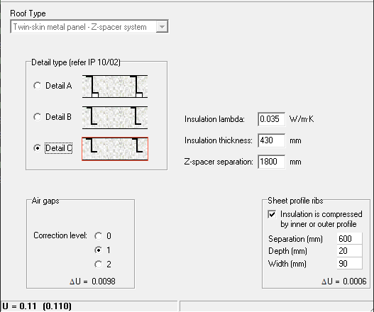
211.External wall construction details - 2022 Notional building (not involving metal cladding)
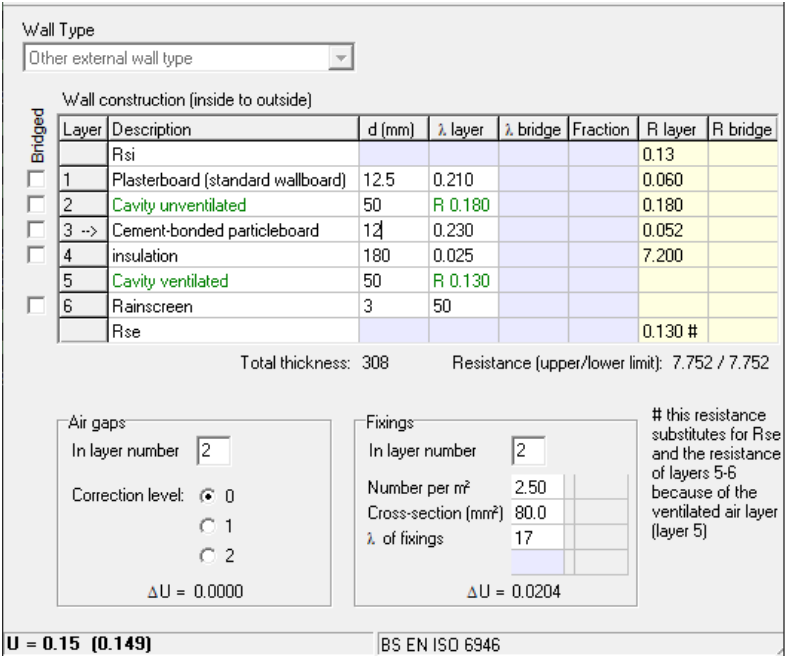
Page 57
#Source page 57
212.External wall construction details - 2022 Notional building (involving metal cladding) –
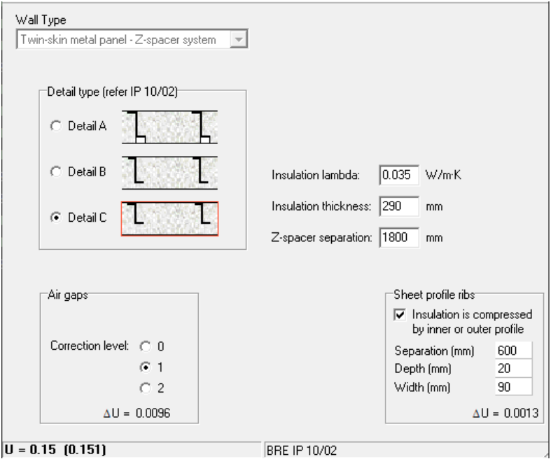
213.Exposed floor construction details - 2022 Notional building
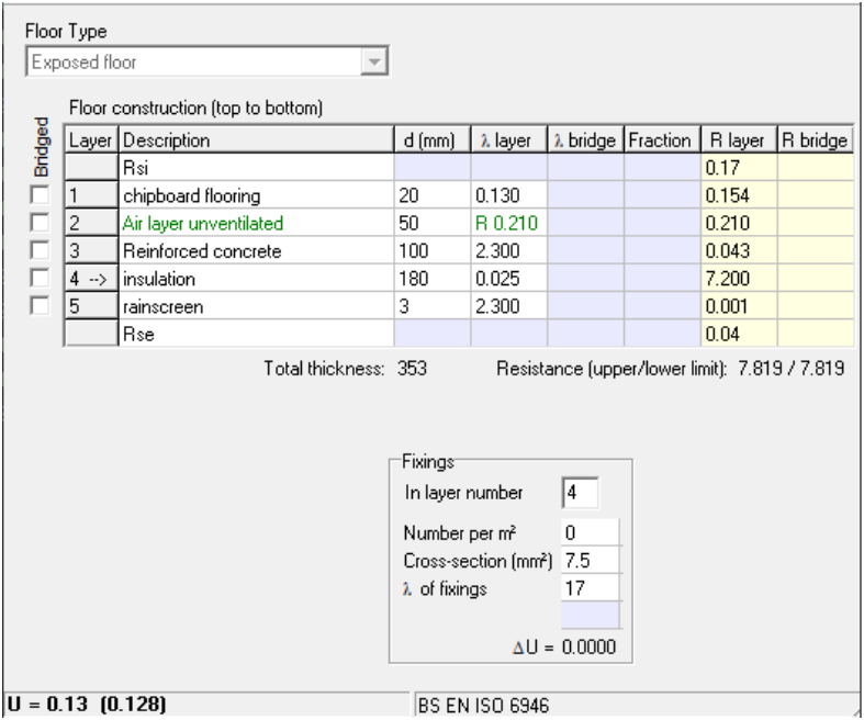
Page 58
#Source page 58
214.Ground floor construction details - 2022 Notional building
(note that the aspect ratio and edge insulation parameters have not been set as these details are intended only for determining the thermal capacity as viewed from inside) –
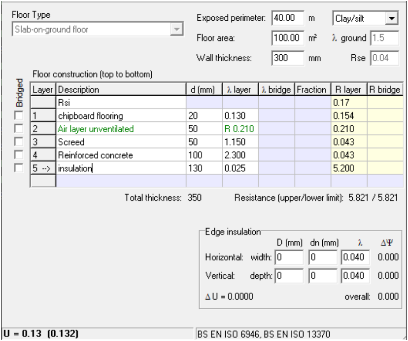
215.Vehicle access and similar large door construction details - 2022 Notional building
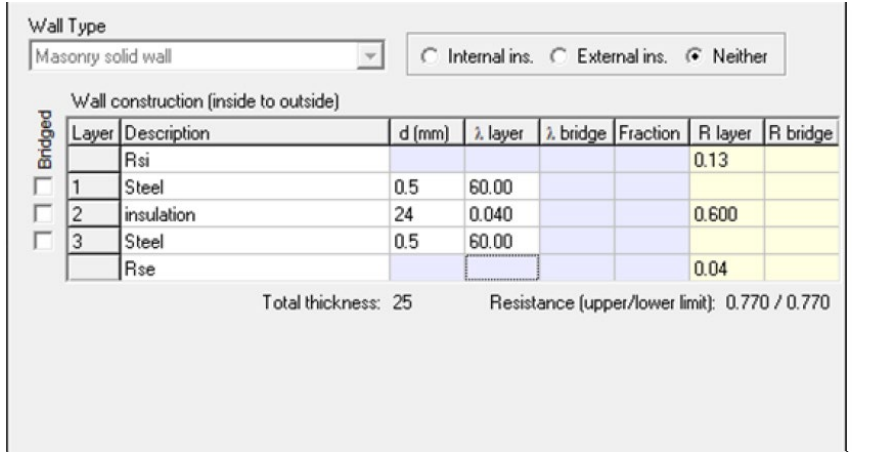

Page 59
#Source page 59
216.Pedestrian & high usage entrance doors construction details - 2022 Notional building –
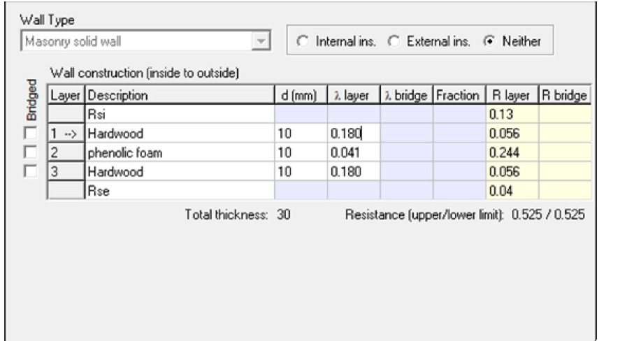

217.Internal floor/ceiling construction details - 2022 Notional building –
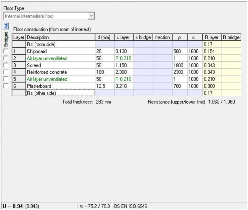
Page 60
#Source page 60
218.Internal partition construction details – 2022 Notional building –