Wales Approved Document F
Approved Document F: volume 1 (dwellings) (takes effect on 4 March 2027)
Library captured 10 September 2026 · Source updated 29 August 2026
Page 1
#Source page 1

2026 version - For use in Wales*
2026 edition
#Source page 2
This Approved Document supports Part F of Schedule 1 to the Building Regulations 2010.
This Approved Document takes effect on 4 March 2027 for use in Wales. It does not apply to work on a particular building where a building notice, full plans application or initial notice have been submitted before that date, provided the work for each building is started before 4 March 2028 Full detail of the transitional arrangements can be found in Circular Letter 003/2026 published on Building regulations | Sub-topic | GOV.WALES
This approved document gives guidance for compliance with the Building Regulations for building work carried out in Wales.
© Crown copyright 2026, Welsh Government,
WG54476, Digital ISBN 978-1-83745-486-0
The approved documents
#Source page 4
Contents > The approved documents > Section 0 | 1 | 2 | 3 | 4 > Appendix A | B | C | D | E | F
The approved documents
The approved documents
What is an approved document?
This Approved Document, which takes effect on 4 March 2027, has been approved and issued by the Welsh Ministers to provide practical guidance on ways of complying with the ventilation requirements of the Building Regulations 2010 for Wales, as amended, which are referred to throughout the remainder of this document as ‘the Building Regulations’. Approved documents give guidance on each of the technical parts of the regulations and on Regulation 7.
Approved documents set out what, in ordinary circumstances, may be accepted as reasonable provision for compliance with the relevant requirements of the Building Regulations to which they refer. If you follow the guidance in an approved document, there will be a presumption of compliance with the requirements covered by the guidance. However, compliance is not guaranteed; for example, ‘normal’ guidance may not apply if the particular case is unusual in some way.
Note that there may be other ways to comply with the requirements – there is no obligation to adopt any particular solution contained in an approved document. If you prefer to meet a requirement in some other way than described in an approved document, you should discuss this with the relevant building control body.
Some approved documents include extracts from the Building Regulations 2010. The Building Regulations must be followed exactly.
Each approved document relates only to the particular requirements of the Building Regulations that the document addresses. However, building work must also comply with any other applicable requirements of the Building Regulations.
How to use this approved document
This document uses the following conventions.
a. Text against a blue background is an extract from the Building Regulations 2010 or The Building (Registered Building Control Approvers etc.) (Wales) Regulations 2024 (both as amended). These extracts set out the legal requirements of the regulations.
b. Key terms, printed in blue, are defined in Appendix A c. When this approved document refers to a named standard or other document, the relevant version is listed in Appendix E (standards) or Appendix F (other documents)
However, if the issuing body has revised or updated the listed version of the standard or document, you may use the new version as guidance if it continues to address the relevant requirements of the Building Regulations.
d. Additional commentary in italic text appears after some numbered paragraphs
Where you can get further help
#Source page 5
Contents > The approved documents > Section 0 | 1 | 2 | 3 | 4 > Appendix A | B | C | D | E | F
The approved documents
This commentary is intended to assist understanding of the immediately preceding paragraph or sub-paragraph, or to direct readers to sources of additional information, but is not part of the technical guidance itself.
Note: Standards and technical approvals may also address aspects of performance or matters that are not covered by the Building Regulations, or they may recommend higher standards than required by the Building Regulations.
Where you can get further help
If you do not understand the technical guidance or other information in this approved document or the additional detailed technical references to which it directs you, you can seek further help through a number of routes, some of which are listed below.
a. The Welsh Government website: https://gov.wales/building-regulations b. If you are the person undertaking the building work: either from your local authority building control service or from a registered building control approver c. If you are registered with a competent person scheme: from the scheme operator d. If your query is highly technical: from a specialist or an industry technical body for the relevant subject
The Building Regulations
The following is a high level summary of the Building Regulations relevant to most types of building work. Where there is any doubt you should consult the full text of the regulations, available at www.legislation.gov.uk .
Building work
Regulation 3 of the Building Regulations defines ‘building work’. Building work includes among other things:
a. the erection or extension of a building b. the provision or extension of a controlled service or fitting in or in connection with a building c. the material alteration of a building or a controlled service or fitting
Regulation 4 of the Building Regulations states that building work should be carried out in such a way that, when work is complete:
a. For new buildings or work on a building that complied with the applicable requirements of the Building Regulations: the building complies with the applicable requirements of the Building Regulations b. For work on an existing building that did not comply with the applicable requirements of the Building Regulations:
Material change of use
#Source page 6
Contents > The approved documents > Section 0 | 1 | 2 | 3 | 4 > Appendix A | B | C | D | E | F
The approved documents
(i) the work itself must comply with the applicable requirements of the Building Regulations
(ii) the building must be no more unsatisfactory in relation to the requirements than before the work was carried out
Material change of use
Regulation 5 of the Building Regulations defines a ‘material change of use’ in which a building or part of a building that was previously used for one purpose will be used for another.
The Building Regulations set out requirements that must be met before a building can be used for a new purpose. To meet the requirements, the building may need to be upgraded in some way.
Materials and workmanship
In accordance with Regulation 7 of the Building Regulations, building work must be carried out in a workmanlike manner using adequate and proper materials. Guidance on materials and workmanship is given in Approved Document 7.
Energy efficiency requirements
Part 6 of the Building Regulations imposes additional specific requirements for energy efficiency.
If a building is extended or renovated, the energy efficiency of the existing building or part of it may need to be upgraded.
Notification of work
Most building work and material changes of use must be notified to a building control body unless one of the following applies.
a. It is work that will be self-certified by a registered competent person b. It is work exempted from the need to notify by regulation 12(6A) of, or Schedule 4 to, the Building Regulations
Responsibility for compliance
People who are responsible for building work (e.g. agent, designer, builder or installer) must ensure that the work complies with all applicable requirements of the Building Regulations. The building owner may also be responsible for ensuring that work complies with the Building Regulations. If building work does not comply with the Building Regulations, the building owner may be served with an enforcement notice.
Section 0
#Source page 7
Contents > The approved documents > Section 0 | 1 | 2 | 3 | 4 > Appendix A | B | C | D | E | F
Section 0
Section 0
Introduction
0.1This approved document gives guidance on how to comply with Part F of schedule 1 to the Building Regulations. For guidance relating to non- domestic buildings, use Approved Document F, Volume 2: Buildings other than dwellings. It contains the following sections:
| Approved Document Section | Related Building Regulations requirements |
|---|---|
| Section 0: Introduction | N/A |
| Section 1: Ventilation provision | Requirement F1(1) |
| Section 2: Minimising the ingress of external pollutants | Requirement F1(1) |
| Section 3: Work on existing dwellings | Requirement F1(1) |
| Section 4: Commissioning and providing information | Requirement F1(2) and regulations 39, 42 and 44 |
| Appendix A: Key terms | N/A |
| Appendix B: Performance-based ventilation | N/A |
| Appendix C: Completion checklist and commissioning sheet | N/A |
| Appendix D: Checklist for ventilation provision in existing dwellings | N/A |
| Appendix E: Standards referred to | N/A |
| Appendix F: Documents referred to | N/A |
Application
0.2The recommendations of this volume of this approved document apply to work in dwellings only. For blocks of flats with shared communal rooms, Approved Document F, Volume 2: Buildings other than dwellings should be consulted.
•Note: Dwellings are self-contained units. Rooms for residential purposes and buildings that contain only rooms for residential purposes are not dwellings and are covered by Approved Document F, Volume 2: Buildings other than dwellings.
Exemptions
#Source page 8
Contents > The approved documents > Section 0 | 1 | 2 | 3 | 4 > Appendix A | B | C | D | E | F
Section 0
Exemptions
0.3The following classes of buildings are exempt from the Part F requirements:
a.special buildings – any of the following:
i.buildings controlled under the Manufacture and Storage of Explosives Regulations 2014
ii.buildings controlled under the Nuclear Installations Act 1965
iii.buildings included in the schedule of monuments maintained under section 3 of the Historic Environment (Wales) Act 2023
b. unoccupied buildings – either of the following:
i.detached buildings into which people do not normally go
ii.detached buildings into which people go only occasionally to inspect or maintain fixed plant, provided that the buildings are a specified distance from buildings into which people normally go, as defined in the Building Regulations 2010 Schedule II
c. greenhouses - provided that the main purpose of the building is not retailing, packing or exhibiting d. agricultural buildings (as defined in the Building Regulations 2010 Schedule II) - provided that all of the following apply:
i.no part of the building is used as a dwelling
ii.the building is at least one and one-half times its height from a building containing sleeping accommodation
iii.there is a fire exit not more than 30 metres distant from any point in the building
Agricultural buildings used mainly for retailing, packing or exhibiting are not exempt;
e. temporary buildings – buildings that are not intended to remain for more than 28 days f. ancillary buildings – any of the following:
i.buildings used for the disposal of buildings or building plots on site
ii.buildings on the site of construction or civil engineering works that both:
a.are for use only during the course of those works
b.contain no sleeping accommodation
iii.buildings on the site of mines and quarries that both:
a.do not contain dwellings
b.are not used as offices or showrooms
g. small buildings – detached single-storey buildings with a maximum floor area of 30 m 2 , that contain no sleeping accommodation, and that are either:
Historic and traditional buildings
#Source page 9
Contents > The approved documents > Section 0 | 1 | 2 | 3 | 4 > Appendix A | B | C | D | E | F
Section 0
i.constructed substantially of non-combustible material
ii.at least 1 metre from the boundary of their curtilage
h. very small buildings – detached buildings with a maximum floor area of 15 m 2 floor area that contain no sleeping accommodation i. bomb shelters – detached buildings with a maximum floor area of 30 m 2 that are designed and intended to be used as shelters from nuclear, chemical or conventional weapons, and for no other purpose, provided the site of the excavation for the building is a minimum of 1 metre plus the depth of excavation from any other exposed structure, and j. conservatories and porches – extensions of buildings at ground level, with a maximum floor area of 30 m 2, for a:
i.conservatory
ii.porch
iii.covered yard
iv.covered way
v.carport open on at least two sides
Historic and traditional buildings
0.4As mentioned above in paragraph 0.3a, buildings included in the schedule of monuments maintained under section 3 of the Historic Environment (Wales) Act 2023 are exempt from compliance with the requirements of the Building Regulations. There are other classes of buildings where special considerations may apply in deciding what is adequate provision for ventilation:
a. listed buildings b. buildings in conservation areas c. buildings which are of architectural and historical interest and which are referred to as a material consideration in a local authority’s development plan or local development framework d. buildings which are of architectural and historical interest within national parks, areas of outstanding natural beauty, registered historic parks and gardens, registered battlefields, the curtilages of scheduled monuments, and world heritage sites; and e. buildings of traditional construction with permeable fabric that both absorbs and readily allows the evaporation of moisture
0.5When undertaking work on or in connection with a building that falls within one of the classes listed above, the aim should be to provide adequate ventilation as far as is reasonable and practically possible. The work should not prejudice the character of the host building or increase the risk of long-term deterioration of the building fabric or fittings.
Selected Key Interactions with other parts of the Building Regulations
#Source page 10
Contents > The approved documents > Section 0 | 1 | 2 | 3 | 4 > Appendix A | B | C | D | E | F
Section 0
0.6The guidance given in BS 7913 Principles of the conservation of historic buildings should be taken into account in determining appropriate ventilation strategies for building work in historic buildings.
0.7In general, new extensions to historic or traditional dwellings should comply with the standards of ventilation as set out in this Approved Document. The only exception would be where there is a particular need to match the external appearance or character of the extension to that of the host building.
0.8Particular issues relating to work in historic buildings that warrant sympathetic treatment and where specialist professional advice from others could therefore be beneficial include:
a. restoring the historic character of a building that has been subject to previous inappropriate alteration, e.g. replacement windows, doors and rooflights b. rebuilding a former historic building (e.g. following a fire or filling a gap site in a terrace) c. making provision for the fabric of historic buildings to control moisture (as originally intended) and avoid potential long-term deterioration
0.9In determining what is adequate ventilation in the circumstances, it is important that the building control body takes into account the advice of the local authority’s conservation officer. The views of the conservation officer are particularly important where building work requires planning permission and/or listed building consent.
Selected Key Interactions with other parts of the Building Regulations
0.10The approved documents set out what, in ordinary circumstances, may be accepted as one way to comply with the Building Regulations. Those designing or undertaking building work remain responsible for assessing, on a case-by- case basis, whether specific circumstances require additional or alternative measures to comply with the regulatory requirements. There are interactions between many of the requirements of the Building Regulations. Guidance on some key interactions is given below.
0.11The adoption of any particular ventilation measure should not involve unacceptable technical risk with another technical requirement within the Building Regulations. Some examples of interaction with other technical requirements are given below.
Interaction with Part B
#Source page 11
Contents > The approved documents > Section 0 | 1 | 2 | 3 | 4 > Appendix A | B | C | D | E | F
Section 0
Interaction with Part B
0.12The requirements of Part B apply if ducts pass through any of the following:
i.a fire-resisting structure
ii.a fire compartment
iii.a protected stairway
0.13This document gives guidance on window openings for ventilation. In addition, Approved Document B gives guidance on the size of escape windows. The larger of the window openings in Approved Document B or F should be applied in all cases.
Interaction with Part J
0.14Ventilation fans might cause combustion gases to spill from open-flued appliances. These combustion gases might fill the room instead of going up the flue or chimney, even if the combustion appliance and fan are in separate rooms.
0.15The guidance in Approved Document J should be followed when installing and testing ventilation appliances. Combustion appliances must operate safely whether or not fans are running.
Interaction with Part L
0.16Energy efficiency should be considered when specifying ventilation systems. Energy efficiency, including the control of infiltration, is dealt with under Part L of the Building Regulations.
Interaction with Parts K and M
0.17Where manual controls are provided for a ventilation device, they should be within reasonable reach of the occupants. Guidance is provided within Approved Documents K and M.
Interaction with Parts O
0.18This document sets minimum standards for purge ventilation for rapidly diluting indoor air pollutants and extracting water vapour where necessary in habitable rooms in dwellings. For domestic-type buildings, Part O may require a higher standard than the guidance given in this document for purge ventilation to remove excess heat. In this case, the higher of the two standards should be followed.
Interaction with Parts Q
0.19Where windows and doors are in easily accessible locations the impact of purge ventilation openings should be considered in relation to property security against unauthorised access. Guidance is provided within Approved Document Q.
Notification of work covered by the ventilation requirements
#Source page 12
Contents > The approved documents > Section 0 | 1 | 2 | 3 | 4 > Appendix A | B | C | D | E | F
Section 0
Notification of work covered by the ventilation requirements
0.20Notifiable ventilation work on a building should usually be notified to a building control body before the work starts. However, work may be notified after it starts in any of the following situations:
i.Where work will be carried out by a person registered with a competent person self-certification scheme (paragraphs 0.21 to 0.23)
ii.When the work is emergency repairs (paragraph 0.24)
iii.When the work is minor works (paragraph 0.25)
Competent person self-certification schemes
0.21Where work is to be carried out by a person registered with a competent person scheme, it is not necessary to notify a building control body in advance.
0.22If work is carried out by a person registered with a competent person scheme, both:
i.The occupier of the building must be given a certificate to confirm that the work complies fully with all relevant requirements of the Building Regulations. This certificate must be provided within 30 days of the work being completed
ii.The building control body must be given a notice of the work carried out, within 30 days of the work being completed
0.23Building control bodies may accept notices and certificates from a person registered with a competent person scheme as evidence of compliance with the requirements of the Building Regulations. The local authority still retains inspection and enforcement powers in these circumstances.
Note: A list of competent person schemes and the types of work for which they are authorised is available at https://www.gov.wales/building-work-competent-person- schemes#120483
Emergency repairs
0.24For emergency repairs, if it is not practicable to notify the building control body in advance, the building control body should be notified at the earliest opportunity. If the installer is registered in a competent person scheme, the normal requirements in paragraphs 0.21 to 0.23 would apply.
Minor works
#Source page 13
Contents > The approved documents > Section 0 | 1 | 2 | 3 | 4 > Appendix A | B | C | D | E | F
Section 0
Minor works
0.25Where the work is of a minor nature as described in the schedule of non- notifiable work (Schedule 4 to the Building Regulations), the work must still comply with the relevant requirements but need not be notified to the building control body.
0.26For mechanical ventilation and air-conditioning systems, minor works include any of the following:
a. Replacing parts b. Adding an output or control device if testing and adjusting the system would not affect its energy efficiency or would not be possible c. Providing a self-contained mechanical ventilation or air-conditioning appliance when all the following apply:
i. Any electrical work is exempt from a requirement to give advance notice to a building control body ii. Testing and adjusting the system would not affect its energy efficiency or would not be possible
iii.The appliance is not installed in a room that contains an open-flued combustion appliance
Live-work units
0.27A unit that contains both living accommodation and space for commercial purposes (e.g. for a workshop or office) should be treated as a dwelling if the commercial part can be reverted to domestic use. The commercial part of the building can be reverted to domestic use if all of the following apply:
a. There is direct access between the commercial space and the living accommodation b. The commercial space and living accommodation are within the same thermal envelope c. The living accommodation comprises a substantial proportion of the total area of the unit. What constitutes a ‘substantial proportion’ should be assessed on a case-by-case basis by the building control body
Mixed use developments
0.28When constructing a dwelling as part of a larger building that contains other types of accommodation, sometimes called a mixed-use development, refer to the two volumes of Approved Document F as follows:
a. For guidance on each individual dwelling, use this approved document: Approved Document F, Volume 1: Dwellings b. For guidance on the non-dwelling parts of the building, such as shared communal rooms and commercial or retail space, use Approved Document F, Volume 2: Buildings other than dwellings
Requirement F1(1): Means of ventilation
#Source page 14
Contents > The approved documents > Section 0 | 1 | 2 | 3 | 4 > Appendix A | B | C | D | E | F
Section 0
Requirement F1(1): Means of ventilation
This Approved Document deals with the Requirements of Part F1(1) of Schedule 1 to the Building Regulations 2010.
| Requirement | |
| Requirement | Limits on application |
| Means of ventilation F1(1). There shall be adequate means of ventilation provided for people in the building. | Requirement F1 does not apply to a building or space within a building: a. into which people do not normally go; or b. which is used solely for storage; or c. which is a garage used solely in connection with a single dwelling. |
Intention
In the Welsh Minister’s view, Requirement F1(1) will be met if the dwelling has a means of ventilation that achieves all of the following:
a.extracts water vapour and indoor air pollutants from areas where they are produced in significant quantities (e.g. kitchens, utility rooms and bathrooms) before they spread through the building, following guidance for extract ventilation in paragraphs 1.21 to 1.27
b.supplies a minimum level of outdoor air for occupants’ health, following the guidance for the whole dwelling ventilation in paragraphs 1.28 to 1.30
c.rapidly dilutes indoor air pollutants and disperses water vapour when necessary in habitable rooms, following the guidance for purge ventilation in paragraphs 1.31 to 1.36
d.minimises the entry of external air pollutants, following the guidance in Section 2
e.achieves all of the following as far as reasonably practicable:
•produces low levels of noise, following the guidance in paragraphs 1.50 to 1.52
•offers easy access for maintenance, following the guidance in paragraph 1.53
•provides protection from cold draughts
In the Welsh Minister’s view, Requirement F1(1) is met for work on an existing dwelling by following guidance in Section 3.
Section 1
#Source page 15
Contents > The approved documents > Section 0 | 1 | 2 | 3 | 4 > Appendix A | B | C | D | E | F
Section 1
Section 1
Ventilation provision
General
1.1The aim of Requirement F1(1) is to protect the health of occupants of the building by providing adequate ventilation. Without adequate ventilation, mould and internal air pollution might become hazardous to health.
Note: The guidance in this Approved Document is not designed to deal with the products of tobacco smoking or vaping.
1.2The building should provide the ventilation rates given in this section.
1.3Other ventilation solutions may be used, provided it can be demonstrated to the building control body that they meet Requirement F1(1).
1.4The ventilation rates set out in this Approved Document have been designed to meet the pollutant levels in Appendix B where the outside air is of reasonable quality. In areas where the outside air is not of reasonable quality, Section 2 provides guidance on limiting the entry of external air pollutants.
Installation, certification, inspection and testing of mechanical ventilation systems
1.5When installing mechanical ventilation systems, particularly centralised systems, extra care should be taken to make sure that both of the following are met:
a. The person carrying out the work is suitably competent (for example, they are a registered competent person) b. The work meets the requirements of the Building Regulations
1.6For ventilation installation work, one of the following two procedures must be used to certify that the work complies with the requirements set out in the Building Regulations:
a. Self-certification by a registered competent person b. Certification by a building control body
1.7To verify that the design, installation and commissioning of the mechanical ventilation system meets the requirements of the Building Regulations, the installation work should be inspected and tested to show that it meets all of the relevant requirements, which are set out in this Approved Document.
Self-certification by a registered competent person
#Source page 16
Contents > The approved documents > Section 0 | 1 | 2 | 3 | 4 > Appendix A | B | C | D | E | F
Section 1
Self-certification by a registered competent person
1.8Mechanical ventilation installers who are registered competent persons should do both of the following:
a. Install and commission the system to the standards set out in this Approved Document b. Give notice to the building control body that commissioning has been carried out in accordance with this Approved Document
Note: The checklist provided in Appendix C may help to make sure that the relevant standards have been met.
1.9The mechanical ventilation installer or the installer’s registration body must within 30 days of the work being completed do both of the following:
a. Give a copy of the Building Regulations compliance certificate to the occupier b. Give the certificate, or a copy of the information on the certificate, to the building control body
Certification by a building control body
1.10If a mechanical ventilation installer is not a registered competent person, then before work begins the installer must either notify the local authority or arrange for a registered building control approver to oversee the work.
1.11The building control body will determine the extent of inspection and testing needed for it to establish that the work is compliant with the Building Regulations requirements, based on the nature of the installation work and the competence of the installer. The building control body should be given notice of when the work has reached relevant stages. The building control body will set out the notification procedure.
1.12Once the building control body has decided that, as far as can be ascertained, the work meets all the Building Regulations requirements, it will issue a Building Regulations completion certificate (if a local authority) or a final certificate (if a registered building control approver).
Note: The checklist provided in Appendix C may help to make sure that the relevant standards have been met.
The ventilation strategy in this Approved Document
#Source page 17
Contents > The approved documents > Section 0 | 1 | 2 | 3 | 4 > Appendix A | B | C | D | E | F
Section 1
The ventilation strategy in this Approved Document
1.13The ventilation strategy in this Approved Document relies on a combination of all of the following:
• Extract ventilation from rooms where water vapour or pollutants are likely to be released, e.g. bathrooms and kitchens, to minimise their spread to the rest of the building
• Ventilation fans may be either intermittent operation or continuous operation
• Whole building ventilation to provide fresh air to the building and to dilute, disperse and remove water vapour and pollutants not removed by extract ventilation
• Purge ventilation to remove high concentrations of pollutants and water vapour. Purge ventilation is used intermittently and required only for pollutants produced by occasional activities (e.g. fumes from painting)
1.14Ventilation may be delivered through natural ventilation, mechanical ventilation or a combination of both.
1.15The ventilation systems in this Approved Document are examples of systems that comply with Part F of the Building Regulations. Other ventilation systems may be acceptable if they can be shown to meet an equal level of performance.
Performance-based guidance
1.16Performance criteria for acceptable levels of moisture and pollutants are given in Appendix B. Ventilation rates designed to meet the performance criteria are given in Tables 1.1 to 1.3.
1.17Ventilator sizes for the whole dwelling are also provided in Table 1.7 to help designers comply with Part F of the Building Regulations in common situations.
1.18Some ventilation system designs can, in some circumstances, result in lower ventilation rates than stated in Tables 1.1 and 1.2 (e.g. systems with automatic controls). Where lower ventilation rates are proposed, expert advice should be obtained to demonstrate that the solution meets the performance standards in Appendix B.
Equivalent area of ventilators
#Source page 18
Contents > The approved documents > Section 0 | 1 | 2 | 3 | 4 > Appendix A | B | C | D | E | F
Section 1
Equivalent area of ventilators
1.19The size of background ventilators (including trickle ventilators) is given in this Approved Document as an equivalent area in mm 2, not as a free area. BS EN 13141-1 includes a method of measuring the equivalent area of background ventilator openings.
1.20Background ventilators should have the equivalent area marked where it will be easily visible from inside the dwelling when installed, to aid verification by Building Control Bodies.
Extract ventilation
1.21Extract ventilation to outside should be provided in all of the following spaces:
•kitchens
•utility rooms
•bathrooms
•sanitary accommodation
1.22Extract ventilation can be intermittent or continuous.
1.23Minimum extract ventilation rates in litres per second (l/s) for intermittent operation extract systems are specified in Table 1.1. Minimum extract ventilation rates for continuous operation extract systems are specified in Table 1.2.
1.24Extract ventilation terminals and fans, not including cooker extract hoods, should be installed to comply with both of the following conditions:
•as high as is practicable in the room
•not more than 400 mm below the ceiling
1.25Where a cooker hood is used to extract to the outside, the height of the extract hood above the hob surface should be either as specified in the manufacturer’s instructions, or if no specification is available, between 650 mm and 750 mm.
Table 1.1 Minimum extract ventilation rates for intermittent extract systems
#Source page 19
Contents > The approved documents > Section 0 | 1 | 2 | 3 | 4 > Appendix A | B | C | D | E | F
Section 1
Table 1.1 Minimum extract ventilation rates for intermittent extract systems
| Room | Intermittent extract rate |
| Kitchen (cooker hood extracting to outside)¹ | 30 litres per second |
| Kitchen (no cooker hood or cooker hood does not extract to outside) ² | 60 litres per second |
| Utility room | 30 litres per second |
| Bathroom | 15 litres per second |
| Sanitary accommodation ³ | 6 litres per second |
| Notes: 1. See Diagram 1.1 2. See Diagram 1.2. 3. As an alternative for sanitary accommodation, the purge ventilation guidance may be used. |
Diagram 1.1 – Minimum ventilation rate for kitchen extract where cooker hood extracts to outside 1
#Source page 20
Contents > The approved documents > Section 0 | 1 | 2 | 3 | 4 > Appendix A | B | C | D | E | F
Section 1
Diagram 1.1 – Minimum ventilation rate for kitchen extract where cooker hood extracts to outside 1
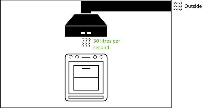
| Notes: 1. The cooker hood should span at least the full width of the cooker. |
Diagram 1.2 – Minimum ventilation rate for kitchen extract where cooker hood does not extract to outside1
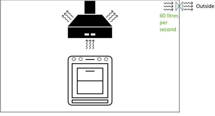
| Notes: 1. This diagram includes a recirculating cooker hood for illustration. A recirculating cooker hood on its own does not provide a means of ventilation that complies with Part F of the Building regulations. |
Table 1.2 Minimum extract ventilation rates for continuous extract systems (1)
#Source page 21
Contents > The approved documents > Section 0 | 1 | 2 | 3 | 4 > Appendix A | B | C | D | E | F
Section 1
1.26Minimum extract ventilation rates for continuous extract systems are specified in Table 1.2. A ‘continuous’ rate is given for the general operation of the fan, and a ‘high’ rate for use during periods when additional extraction is required.
Table 1.2 Minimum extract ventilation rates for continuous extract systems (1)
| Room | High rate | Continuous rate |
| Kitchen | 13 litres per second | The sum of all extract ventilation in the dwelling on its continuous rate should be at least the whole dwelling ventilation rate given in Table 1.3 |
| Utility room | 8 litres per second | |
| Bathroom | 8 litres per second | |
| Sanitary accommodation | 6 litres per second | |
| Note: 1. If the continuous rate of ventilation provided in a room is equal to or higher than the minimum high rate specified in the table, no extra ventilation is needed. |
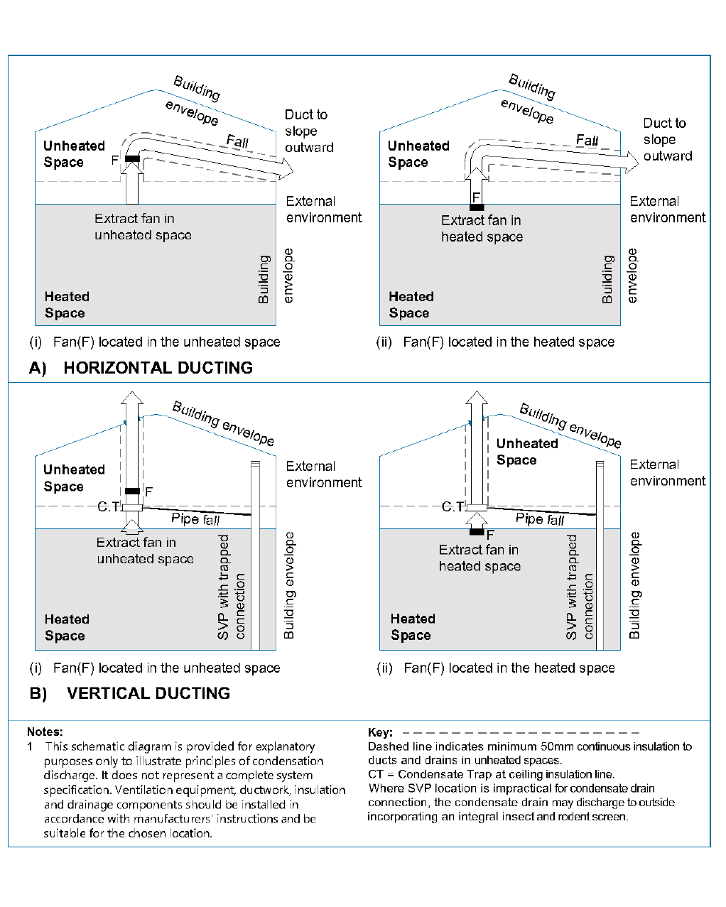
1.27Ducts passing through unheated spaces leading to external air terminals should be insulated following paragraph 1.93. To minimise the risk of damage from internal duct condensation, the following provisions apply:
a.Horizontal ducts should incorporate a continuous fall towards the external air terminal to allow condensation to discharge via the terminal or to a main drain, as shown in diagram 1.3
b.Vertical ducts that discharge to an external roof terminal should incorporate a condensate trap located at the base of the vertical duct section. The trap should discharge to the outside or to a main drain, as shown in diagram 1.3
Note: Where a condensate trap or pipe connect to foul water drainage systems, a waterless trap should be installed to prevent the ingress of foul air.
Diagram 1.3 - Provisions to discharge condensation within ductwork leading to external air terminals
#Source page 22
Contents > The approved documents > Section 0 | 1 | 2 | 3 | 4 > Appendix A | B | C | D | E | F
Section 1
Diagram 1.3 - Provisions to discharge condensation within ductwork leading to external air terminals
Whole dwelling ventilation
#Source page 23
Contents > The approved documents > Section 0 | 1 | 2 | 3 | 4 > Appendix A | B | C | D | E | F
Section 1
Whole dwelling ventilation
1.28Supply air for the dwelling should be delivered through one of the following means:
•Continuous supply fans
•Background ventilators
1.29The minimum whole dwelling ventilation rate for the supply of air to the habitable rooms in a dwelling should meet both of the following conditions:
a. A minimum rate of 0.3 litres per second per m2 of internal floor area (this includes all floors, e.g. for a two-storey building, add the ground-floor and first-floor areas) b. A minimum rate determined by the number of bedrooms, as specified in Table 1.3
Table 1.3 Minimum whole dwelling ventilation rates 1,2
| Number of bedrooms | 1 | 2 | 3 | 4 | 5 |
| Minimum ventilation rate by number of bedrooms (l/s) | 19 | 25 | 31 | 37 | 43 |
| Notes: 1. If the dwelling has only one habitable room, a minimum ventilation rate of 13 l/s should be used. 2. For each additional bedroom, add 6 litres per second to the values in Table 1.3. |
1.30Internal doors should allow air to flow through the dwelling by providing a minimum free area equivalent to a 10mm undercut in a 760mm wide door. Doors should be undercut to achieve one of the following:
•If the floor finish is fitted: 10mm above the floor finish
•If the finish is not fitted: 20mm above the floor surface
Purge ventilation
1.31A system for purge ventilation should be provided in each habitable room.
1.32Purge ventilation should be capable of extracting at least four air changes per hour per room directly to the outside.
Table 1.4 Purge ventilation openings
#Source page 24
Contents > The approved documents > Section 0 | 1 | 2 | 3 | 4 > Appendix A | B | C | D | E | F
Section 1
Note: In order to demonstrate compliance with Part O of the Building Regulations it is likely that higher ventilation rates will be required in certain types of dwelling (e.g. flats).
1.33Purge ventilation should be delivered through one of the following means:
•openings (e.g. windows or doors)
•a mechanical extract ventilation system
1.34Where purge ventilation is delivered through openings in a habitable room, the minimum opening areas in Table 1.4 should be achieved. The values in Table 1.4 are based on BS 5925, which assumes all of the following:
•single-sided ventilation
•an urban environment
•a wind speed of 2.1 metres per second (m/s)
•a temperature difference of 3°C between the air inside and outside of the building
1.35Depending on the dwelling design or the external climate, it may be possible in other circumstances to achieve four air changes per hour with smaller openings. If smaller openings than Table 1.4 are specified, expert advice should be sought to ensure the design complies with requirement F1(1).
Table 1.4 Purge ventilation openings
| Opening type | Minimum total area of openings |
| Hinged or pivot windows with an opening angle of 15 to 30 degrees | 1/10 of floor area of room |
| Hinged or pivot windows with an opening angle of greater than or equal to 30 degrees Opening sash windows External doors | 1/20 of floor area of room |
1.36Hinged or pivot windows with an opening angle of less than 15 degrees are not suitable for purge ventilation.
Performance testing
#Source page 25
Contents > The approved documents > Section 0 | 1 | 2 | 3 | 4 > Appendix A | B | C | D | E | F
Section 1
Performance testing
1.37The air flow resistance of all components should be considered when specifying ventilation systems. The complete assembly, as installed, should be designed to meet the performance requirements of this Approved Document. The performance of the separate components should be measured according to the relevant parts of BS EN 13141 and other relevant standards. The relevant test standards for common equipment types are given in Table 1.5.
Table 1.5 Performance testing standards
| Equipment type | Test standard |
| Intermittent extract fans | BS EN 13141-4 |
| Cooker hoods | BS EN 13141-3 |
| Background ventilators without humidity control | BS EN 13141-1 clauses 5.1 and 5.2 Background ventilators should meet the performance standards for both of the following: a. Air flow from outside to inside the dwelling b. Air flow from inside the dwelling to outside |
| Continuous mechanical extract systems | BS EN 13141-6 |
| Mechanical ventilation with heat recovery | BS EN 13141-7 |
| BS EN 13141-8. For internal and external leakage and for mixing, the unit should meet at least Class U4 of the standard. |
Control of ventilation
1.38Ventilation should be controllable. Controls may be either manual (i.e. operated by the occupant) or automatic.
1.39Background ventilators should be a minimum of 1.7m above floor level, to reduce cold draughts, but still be within easy reach of the occupant.
Note: Background ventilators are intended to normally be left open.
1.40Continuously running fans should be set up to operate without occupant intervention, but may have manual or automatic controls to select the high rate of operation. Any manual high rate controls should be provided locally to the spaces being served, e.g. bathrooms and kitchens. Automatic controls might include sensors for humidity, occupancy/usage and pollutant release.
Ventilation systems for dwellings with basements
#Source page 26
Contents > The approved documents > Section 0 | 1 | 2 | 3 | 4 > Appendix A | B | C | D | E | F
Section 1
1.41Controls based on humidity sensors may be installed in moisture-generating rooms (e.g. kitchen or bathroom) but should not be used for sanitary accommodation, where odour is the main pollutant.
1.42Other types of automatic control might be suitable. Where present, automatic controls should operate according to the need for ventilation in the space. Background ventilators with automatic controls should also have manual override.
Note: Where a combustion appliance is installed, any automatic controls must also ensure that the ventilation provided meets the requirements of Part J of the Building regulations.
Ventilation systems for dwellings with basements
1.43In addition to paragraphs 1.16 to 1.42, the performance required for ventilation systems for dwellings with basements would be achieved by following the guidance in paragraphs 1.44 to 1.46.
1.44A dwelling that includes a basement connected to the rest of the dwelling by a large permanent opening (e.g. an open stairway) may be treated as a multi- storey dwelling when following the guidance in this Approved Document for dwellings without basements.
Note: If a basement has only one exposed façade, the guidance for natural ventilation given in this Approved Document would not be appropriate. In such cases, expert advice should be sought.
1.45A dwelling with a basement that is not connected to the rest of the dwelling above ground by a large permanent opening should be considered as follows:
a. The part of the dwelling above ground should be considered separately b. The basement should be treated separately as a single-storey dwelling above ground level c. If the basement has no bedrooms, it should be treated as having one bedroom when calculating the ventilation required for the purposes of meeting the ventilation standards
1.46A dwelling that is only a basement should be treated as a single-storey dwelling above ground level. In such circumstances, the guidance for dwellings without basements should be followed. The guidance on natural ventilation, however, is not appropriate for a dwelling that comprises only a basement.
Ventilation of a habitable room through another room
#Source page 27
Contents > The approved documents > Section 0 | 1 | 2 | 3 | 4 > Appendix A | B | C | D | E | F
Section 1
Ventilation of a habitable room through another room
1.47If a habitable room does not contain openable windows (i.e. an internal room), the requirement for adequate ventilation can be met using paragraphs 1.48 and 1.49 if the room is ventilated through either of the following:
•another habitable room
•a conservatory
1.48The habitable room or conservatory should have openings to outside to provide both of the following:
i. purge ventilation with a minimum total area given in paragraph 1.34 based on the combined floor area of the habitable rooms (or the habitable room and the conservatory) ii. background ventilation of at least 10,000mm 2 equivalent area
1.49Between the two rooms there should be a permanent opening with a minimum area of 1/20 of the combined floor area of the two rooms. See Diagram 1.4.
Note: Conservatories that are exempt from the Building Regulations should be thermally separated from the rest of the dwelling. Paragraph 1.49 does not apply to exempt conservatories.
Section 1
#Source page 28
> > | | | > | |
Section 1
Diagram 1.4. Two habitable rooms treated as one room for ventilation purposes
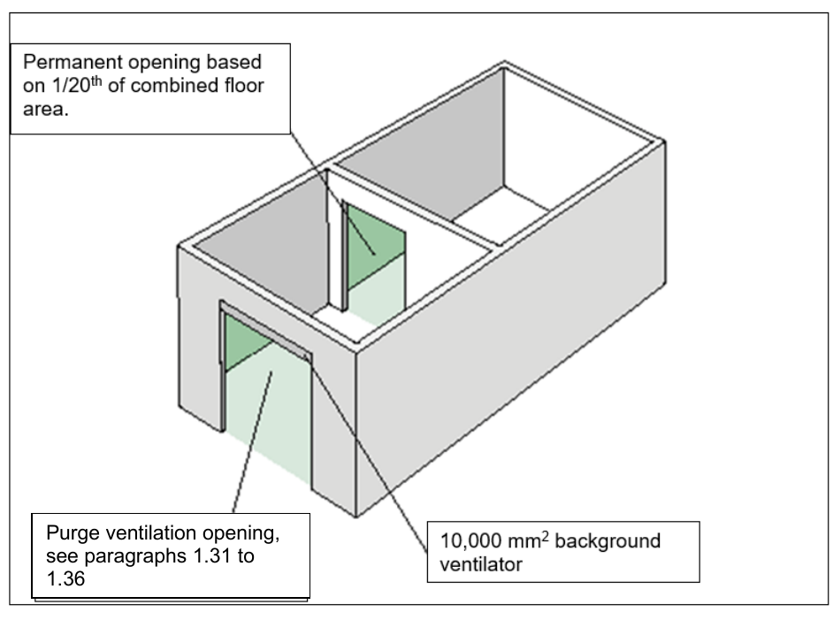
Purge ventilation opening, see paragraphs 1.31 to 1.36
Noise
#Source page 29
Contents > The approved documents > Section 0 | 1 | 2 | 3 | 4 > Appendix A | B | C | D | E | F
Section 1
Noise
1.50Mechanical ventilation systems, including both continuous and intermittent mechanical ventilation, should be designed and installed to minimise noise. This includes doing all of the following.
•Correctly sizing and jointing ducts
•ensuring that equipment is appropriately and securely fixed, such as using resilient mountings where noise carried by the structure of the building could be a problem
•Selecting appropriate equipment, including following paragraph 1.51
1.51For mechanical ventilation systems, fan units should be appropriately sized so that fans operating in normal background ventilation mode are not overly noisy. This might require fans to be sized so that they do not operate near the maximum capacity of the fan when operating in normal background ventilation mode.
1.52Account should be taken of outside noise when considering whether opening windows are suitable for purge ventilation.
Note: When designing the locations and proximities of opening windows relative to other buildings or potential sources of external noise, the designer should also consider the impact of other noise-related guidance and requirements and how they interact with this Approved Document.
•Note: Although there is no requirement to undertake noise testing, achieving the levels in the following guidance would ensure good acoustic conditions. The average A- weighted sound pressure level for a ventilator operating under normal conditions and not at boost rates should not exceed both of the following:
a. 30dB LA eq,T * for noise-sensitive rooms (e.g. bedrooms and living rooms) when a continuous mechanical ventilation system is running on its minimum low rate b. 45dB LAeq,T * in less noise-sensitive rooms (e.g. kitchens and bathrooms) when a continuous operation system is running at the minimum high rate or an intermittent operation system is running
* The noise index L Aeq,T is used in BS 8233, where T is the duration of the measurement. If the noise from the sound source is steady (i.e. fluctuating by up to 3dB), a measuring time of 1 minute will be adequate and the LAeq, 1 min level will be similar to the dB(A) level used elsewhere. lf the noise from the sound source fluctuates more than this, a longer measuring time (T) may be required, but the higher portion of the fluctuating level should be considered, and the sound may attract more attention due to the changes in level.
Access for maintenance
#Source page 30
Contents > The approved documents > Section 0 | 1 | 2 | 3 | 4 > Appendix A | B | C | D | E | F
Section 1
•Methods for measuring the sound power level produced by the fan unit of decentralised extract ventilation, centralised extract ventilation and balanced mechanical ventilation with heat recovery systems are described in BS EN 13141.
Access for maintenance
1.53Reasonable access should be provided for maintaining ventilation systems, including both of the following:
a. providing access to replace filters, fans and coils b. providing access for the general maintenance of the plant and ductwork
System specific guidance
1.54Paragraphs 1.55 to 1.83 give guidance for the following types of ventilation system listed in Table 1.6:
Table 1.6 Types of ventilation system
| System type | Dwellings covered by the guidance |
|---|---|
| Natural ventilation (paragraphs 1.56 to 1.68) | Less airtight dwellings |
| Continuous mechanical extract ventilation (paragraphs 1.69 to 1.75) | All dwellings (both less airtight dwellings and highly airtight dwellings) |
| Mechanical ventilation with heat recovery (paragraphs 1.76 to 1.83) | All dwellings (both less airtight dwellings and highly airtight dwellings) |
Note: For situations outside the scope of Table 1.6, expert advice should be sought for the design,sizing and position of ventilators to provide effective ventilation.
1.55Where a dwelling has natural ventilation and a measured air permeability that differs from the design air permeability, so that it is defined as a highly airtight dwelling, one of the following applies:
a.Expert advice should be sought
b.A continuous mechanical extract ventilation system should be installed by following theguidance in paragraphs 1.69 to 1.75
Natural ventilation with background ventilators and intermittent extract fans (guidance only suitable for less airtight dwellings)
#Source page 31
Contents > The approved documents > Section 0 | 1 | 2 | 3 | 4 > Appendix A | B | C | D | E | F
Section 1
Natural ventilation with background ventilators and intermittent extract fans (guidance only suitable for less airtight dwellings)
Intermittent extract
1.56Intermittent extract fans should be fitted in all wet rooms. For kitchens, utility rooms, bathrooms and sanitary accommodation, the extract rates given in Table 1.1 can be met using an intermittent extract fan.
1.57If a wet room has no external walls, the intermittent extract fan should extract at four air changes per hour to meet the purge ventilation standards in paragraphs 1.31 and 1.36.
1.58For sanitary accommodation, extract rates can be met using windows by following the purge ventilation guidance in paragraphs 1.31 and 1.36.
1.59Any automatic controls (e.g. humidity control) for intermittent extract should have a manual override to allow the occupant to turn the extract ventilation on or off.
1.60In a room with no openable window, an intermittent extract fan should be provided with controls which continue to operate the fan for a minimum of 15 minutes after the room is vacated.
Background ventilators
1.61All rooms with external walls should have background ventilators. If a habitable room has no external walls, paragraphs 1.47 to 1.49 should be followed.
Note: A window with a night latch position is not adequate for background ventilation, due to the following:
•the risk of draughts
•security issues
•the difficulty of measuring the equivalent area
1.62If the dwelling has more than one exposed façade, the area of background ventilators on each façade should be similar, to allow cross-ventilation.
Page 32
#Source page 32
Contents > The approved documents > Section 0 | 1 | 2 | 3 | 4 > Appendix A | B | C | D | E | F
Section 1
1.63If an exposed façade is close to an area of sustained and loud noise (e.g. a main road), then a noise attenuating background ventilator should be fitted.
1.64If fans and background ventilators are fitted in the same room, they should be a minimum of 0.5m apart.
1.65The minimum total area of background ventilators in each room follow the guidance in Table 1.7.
1.66The total number of ventilators installed in the dwelling’s habitable rooms and kitchens should be at least the following:
a.Four ventilators if the dwelling has one bedroom
b.Five ventilators if the dwelling has more than one bedroom
1.67If the dwelling has a kitchen and living room which are not separate rooms, at least three ventilators of the same area as for other habitable rooms in Table 1.7 should be provided in the open-plan space.
Table 1.7 Minimum equivalent area of background ventilators for natural ventilation1
#Source page 33
Contents > The approved documents > Section 0 | 1 | 2 | 3 | 4 > Appendix A | B | C | D | E | F
Section 1
Table 1.7 Minimum equivalent area of background ventilators for natural ventilation1
| Room | Minimum equivalent area of background ventilators for dwellings with multiple floors | Minimum equivalent area of background ventilators for single- storey dwellings |
| Habitable rooms(2)(3) | 8,000mm ² | 10,000mm² |
| Kitchen(2)(3) | 8,000mm ² | 10,000mm² |
| Utility room | No minimum | No minimum |
| Bathroom(4) | 4,000mm ² | 4,000mm ² |
| Sanitary accommodation | No minimum | No minimum |
| Notes: 1) The use of this table is not appropriate in any of the following situations and expert advice should be sought. • If the dwelling has only one exposed façade. • If the dwelling has at least 70% of its openings on the same façade. • If a kitchen has no windows or external façade through which a ventilator can be installed. 2) Where a kitchen and living room accommodation are not separate rooms (i.e. open plan), no fewer than three ventilators of the same equivalent area as for other habitable rooms should be provided within the open-plan space. 3) The total number of ventilators installed in a dwelling’s habitable rooms and kitchens should be no fewer than five, except in one-bedroom properties, where there should be no fewer than four. 4) If a bathroom has no window or external façade through which a ventilator can be installed, the minimum equivalent area specified should be added to the ventilator sizes specified in other rooms. |
Purge ventilation
1.68For purge ventilation follow paragraphs 1.31 to 1.36.
Continuous mechanical extract ventilation
1.69A continuous mechanical extract ventilation system could consist of one of the following:
a.a central extract system (centralised)
b.individual room extract fans (decentralised)
c.a combination of both a central extract system and individual room extract fans
Ventilation rates
#Source page 34
Contents > The approved documents > Section 0 | 1 | 2 | 3 | 4 > Appendix A | B | C | D | E | F
Section 1
1.70If an exhaust air terminal is on the façade exposed to the prevailing wind, measures should be taken to minimise likely wind effects. Solutions could include the following:
a.ducting to another façade
b.use of constant volume flow rate units
c.seeking expert advice
Ventilation rates
1.71The total combined rate of continuous mechanical extract ventilation in the dwelling should be at least the whole dwelling ventilation rate in Table 1.3.
1.72Each wet room should have a minimum continuous mechanical extract ventilation high rate as given in Table 1.2.
Background ventilators for continuous mechanical extract ventilation
1.73Where continuous mechanical extract ventilation is used, background ventilators should satisfy all of the following conditions:
a. not be in wet rooms b. provide minimum equivalent area of 4,000 mm 2 for each habitable room in the dwelling c. Provide a minimum total number of ventilators that is the same as the number of bedrooms plustwo ventilators (i.e. a one-bedroom dwelling should have three background ventilators, a two- bedroom dwelling should have four background ventilators, etc.)
1.74If a habitable room has no external walls, paragraphs 1.47 to 1.49 should be followed.
Purge ventilation
1.75For purge ventilation follow paragraphs 1.31 to 1.36.
Note: The guidance for mechanical extract ventilation is suitable for any level of airtightness.
Mechanical ventilation with heat recovery
Ventilation rates
1.76For dwellings using mechanical ventilation with heat recovery, each habitable room should have mechanical supply ventilation. The total supply air flow should be distributed proportionately to the volume of each habitable room.
Background ventilators
#Source page 35
Contents > The approved documents > Section 0 | 1 | 2 | 3 | 4 > Appendix A | B | C | D | E | F
Section 1
1.77Mechanical supply terminals should be located and directed to avoid draughts.
1.78The minimum total continuous rate of mechanical ventilation with heat recovery is the whole dwelling ventilation rate in Table 1.3.
1.79For dwellings using mechanical ventilation with heat recovery, each wet room should have a minimum continuous mechanical extract ventilation high rate as given in Table 1.2.
1.80Mechanical ventilation with heat recovery systems should be designed to avoid the moist air from the wet rooms recirculating to the habitable rooms.
Background ventilators
1.81To avoid unintended air pathways, background ventilators should not be installed with mechanical ventilation with heat recovery.
Purge ventilation
1.82For purge ventilation follow paragraphs 1.31 to 1.36.
Note: The efficiency of mechanical ventilation with heat recovery systems should improve as the dwelling becomes more airtight.
Condensate drainage
1.83Mechanical ventilation with heat recovery units should be provided with a condensate drain to prevent moisture accumulation within the unit. The following provisions apply:
a.The condensate drain should be connected to a main drain with a minimum fall of 5° from the unit
b.Where the condensate drain passes through an unheated space it should be insulated to prevent freezing during cold weather conditions
•A waterless trap should be installed between the condensate drain and the main drain to prevent the ingress of foul air.
Note: The guidance for mechanical ventilation with heat recovery is suitable for any level of airtightness.
Installation of ventilation systems
#Source page 36
Contents > The approved documents > Section 0 | 1 | 2 | 3 | 4 > Appendix A | B | C | D | E | F
Section 1
Installation of ventilation systems
1.84Ventilation systems should be installed to meet both of the following conditions:
a. Comply with the guidance in this Approved Document b. Meet specific design requirements for the total dwelling air flow rates and the distributed air flow rates for each room in the dwelling
1.85Adequate space should be available for access to maintain ventilation equipment. For continuous mechanical ventilation with heat recovery, access to filters should not necessitate the use of tools or the removal of the main front cover of the unit.
Ducting
1.86Rigid or smooth semi-rigid ducts should be used when installing centralised continuous mechanical extract ventilation and mechanical ventilation with heat recovery systems.
1.87Rigid ducting should be used when installing an intermittent extract fan or decentralised continuous mechanical extract ventilation and the maximum length of duct should be 2.0m where practical.
1.88For all systems with a duct length greater than 2.0m, design calculations and drawings should be provided to the building control body to demonstrate that the fans, along with the connected ducting and external air terminal, can achieve the desired flow rates and that the principles of paragraphs 1.91 and 1.92 have been met. This evidence should be provided by a suitably competent person.
1.89Flexible ductwork should be limited to 200mm in length and used only for final connections to fan unit spigots for centralised continuous mechanical extract ventilation or mechanical ventilation with heat recovery systems.
1.90Any flexible ducts should be installed so that the full internal diameter is maintained and flow resistance is minimised.
Note: For ventilation systems where automatic control of the fan(s) rely on constant pressure within the ductwork, flexible ducting is not permitted in any part of the system.
Table 1.8 Maximum static pressure limit for ductwork installations
#Source page 37
Contents > The approved documents > Section 0 | 1 | 2 | 3 | 4 > Appendix A | B | C | D | E | F
Section 1
1.91Ductwork installations for intermittent extract ,centralised continuous mechanical extract ventilation and mechanical ventilation with heat recovery systems should be designed and installed to minimise the system static pressure within the system through all the following:
a. Minimising the overall length of duct b. Minimising the number of bends and offsets required c. Installing appropriately sized ducts for the air flow rate
1.92The designed system static pressure for centralised continuous mechanical extract ventilation and mechanical ventilation with heat recovery should not exceed the limits in Table 1.8.
Table 1.8 Maximum static pressure limit for ductwork installations
| Total air flow rate range | Continuous mechanical extract ventilation (multiple extract spigots) | Mechanical ventilation with heat recovery and mechanical extract ventilation (single extract spigot) |
| Up to and including 37l/s | 30 Pa | 60 Pa |
| 38 l/s up to and including 53 l/s | 50 Pa | 110 Pa |
| 54l/s and above | 80 Pa | 160 Pa |
1.93Ductwork installations should be insulated as follows:
a. All intake and exhaust air ductwork where it passes through conditioned areas (e.g. the heated part of a dwelling) should be insulated with the equivalent of at least 50mm of a material having a thermal conductivity of ≤0.04 W(m.K). Insulation for intake and exhaust ducts should be fully vapour sealed to minimise the risk of condensation forming b. All supply and extract air ductwork where it passes through unheated areas (e.g. loft spaces and sub-floor voids) should be insulated with the equivalent of at least 25mm of a material having a thermal conductivity of ≤0.04 W(m.K)
1.94Each external air terminal should have a free area of at least 90% of the free area of its associated duct.
1.95Duct connections should be both mechanically secured and adequately sealed to prevent leaks. Mechanical fastenings should be used for flexible ducting to ensure a good seal (e.g. rigid connectors or jubilee clips).
Inspection and testing
#Source page 38
Contents > The approved documents > Section 0 | 1 | 2 | 3 | 4 > Appendix A | B | C | D | E | F
Section 1
Inspection and testing
1.96The installer should make a visual inspection to confirm both of the following:
•There are no obvious defects
•All packaging has been removed
1.97Mechanical ventilation systems must be commissioned in accordance with an approved procedure. Appendix C of this Approved Document includes a completion checklist and commissioning sheet, which the system installer should complete to demonstrate compliance. See Section 4 of this approved document.
Section 2
#Source page 39
Contents > The approved documents > Section 0 | 1 | 2 | 3 | 4 > Appendix A | B | C | D | E | F
Section 2
Section 2
Minimising the ingress of external pollutants
2.1Ventilation systems should be designed to minimise the intake of external air pollutants following paragraphs 2.2 to 2.9 if either of the following applies:
a.The pollutant values in the location of the dwelling exceed any of the limits in Table 2.1. This may have been determined through an air quality assessment. Where modelling or monitoring data is required, expert advice should be sought
b.The dwelling is located near to any of the following sources of significant local pollution:
i.Road traffic, including traffic junctions and underground car parks
ii.Combustion plant (such as heating appliances) running on conventional fuels, mostcommonly natural gas
iii.Other combustion processes (for example, waste incineration, thermal oxidation abatementsystems)
iv.Discharges from industrial processes
v.Fugitive (i.e. not effectively controlled) discharges from industrial processes and othersources
vi.Exhaust discharges from building ventilation systems
vii.Construction and demolition sites, which are a source of particles and vaporous discharges
viii.Other significant sources of local air pollution which may be detrimental to health
Table 2.1 Limit values from Schedule 2 to the Air Quality Standards Regulations 2010
| Pollutant | Exposure limit | Exposure time |
|---|---|---|
| Carbon monoxide | 3 10mg/m | 8-hour average |
| Sulphur dioxide | 3 350μg/m | 1-hour average |
| 3 125μg/m | 1-day average | |
| Nitrogen dioxide | 3 200μg/m | 1-hour average |
| 3 40μg/m | 1-year average | |
| Benzene | 3 5μg/m | 1-year average |
| Lead | 3 0.5μg/m | 1-year average |
| PM 2.5 | 3 25μg/m | 1-year average |
| PM 10 | 3 50μg/m | 1-day average |
| 3 40μg/m | 1-year average |
Control of ventilation intakes
#Source page 40
Contents > The approved documents > Section 0 | 1 | 2 | 3 | 4 > Appendix A | B | C | D | E | F
Section 2
Note: This section only gives guidance for typical situations. Expert advice may also be able to provide additional guidance on the suitability of other technologies to minimise the intake of external air pollutants, including filtration.
Control of ventilation intakes
2.2Ventilation intakes should be located away from the direct impact of the sources of local pollution. Note: CIBSE’s TM64 and TM40 give further guidance.
2.3Where urban traffic is a source of pollution, the air intakes for buildings next to busy urban roads should be both:
•as high as possible
•located on the less polluted side of the building
Mechanical ventilation may be the most practical means of achieving this requirement.
2.4If practicable, ventilation intakes should not be located in courtyards and enclosed urban spaces where air pollutants are discharged. If this is unavoidable, intakes should be both:
•as far as possible from the source of pollutants
•in an open or well-ventilated area
2.5In areas where wind often comes from opposing directions (e.g. a valley), the air intakes in the opposite direction to the exhaust outlets.
2.6Where sources of pollution vary with the time of day, such as urban road traffic, it may be acceptable, for time limited periods to either:
•reduce the flow of external air into ventilation intakes
•close ventilation intakes when the concentrations of external pollutants are highest
Note: In these circumstances, expert advice should be sought.
Location of exhaust outlets
2.7Exhaust outlets should be located so that both:
•Re-entry of exhaust into a building, or entry into other nearby buildings, is minimised
•There is no adverse effect on the surrounding area
2.8Where there is a prevailing wind direction, exhaust outlets should be downwind of intakes.
Page 41
#Source page 41
Contents > The approved documents > Section 0 | 1 | 2 | 3 | 4 > Appendix A | B | C | D | E | F
Section 2
2.9Exhaust outlets should not discharge into any of the following:
•courtyards
•enclosures
•architectural screens
Note: Chapter 13 of the McGraw Hill Indoor Air Quality Handbook provides further guidance.
Section 3
#Source page 42
Contents > The approved documents > Section 0 | 1 | 2 | 3 | 4 > Appendix A | B | C | D | E | F
Section 3
Section 3
Work on existing dwellings
General
3.1When building work is carried out on an existing dwelling includes work on ventilation, for example:
a.adding a habitable room
b.adding a wet room
c.replacing part of the ventilation system, including extract fans
the work should meet the relevant standards in this Approved Document.
3.2When other building work is carried out that will affect the ventilation of the existing dwelling, for example:
a.replacing a window or door
b.doing energy efficiency work
the ventilation of the dwelling should either:
a.meet the standards in the relevant approved document
b.not be less satisfactory than before the work was carried out
Note: Ventilation through infiltration should be considered to be part of the ventilation provision of a dwelling. Reducing infiltration might reduce the indoor air quality of the building below the standards given in Appendix B.
3.3For common types of work, the requirements of paragraph 3.1 and 3.2 may be demonstrated by following the guidance detailed below.
a.For installing energy efficiency measures excluding window replacement, paragraphs 3.6 to 3.13
b.For installing energy efficiency measures including window replacement, paragraphs 3.6 to 3.13 and 3.14 to 3.16
c.For replacing windows only, paragraphs 3.14 to 3.16
d.For the addition of a habitable room, paragraphs 3.17 to 3.20
e.For the addition of a conservatory, paragraphs 3.21 to 3.24
f.For the addition of a wet room, paragraphs 3.25 to 3.29
Installing energy efficiency measures
#Source page 43
Contents > The approved documents > Section 0 | 1 | 2 | 3 | 4 > Appendix A | B | C | D | E | F
Section 3
g.For refurbishing a kitchen or bathroom, paragraphs 3.30 to 3.32
h.For work done to improve the ventilation of the dwelling that was not triggered by the buildingwork in (a) to (g), Section 1 should be followed
3.4Other ventilation solutions than those detailed here may be used, as long as it can be demonstrated to a building control body that they comply with the requirements of paragraphs 3.1 and 3.2.
3.5When a building undergoes a material change of use, Part F of schedule 1 to the Building Regulations applies to the building or part of the building that has changed use. Guidance in Section 1 should be followed.
Note: Ventilation equipment is considered to be a “controlled service or fitting” and the provision or extension of such equipment in or in connection with a building is building work.
Note: Some building work does not need to be notified to the local authority. This is set out in Schedule 4 of the Building Regulations 2010.
Installing energy efficiency measures
3.6Many existing dwellings are ventilated through infiltration rather than purposeful ventilation. Energy efficiency measures carried out on existing dwellings might reduce infiltration and cause the dwelling to become under-ventilated.
Building work should not reduce the ventilation provision of the dwelling, unless it can be demonstrated that the ventilation provision in the dwelling after the work is carried out is equal to the minimum standards of F1(1).
3.7When carrying out energy efficiency measures to an existing dwelling, an assessment should determine what, if any, additional ventilation provision is needed, based on the estimated impact of the work. The assessment should be carried out by one of the following means:
a.Applying the simplified method in paragraphs 3.8 to 3.13
b. Seeking expert advice, which may include carrying out an air permeability test that follows the procedures given in Approved Document L, Volume 1: Dwellings
•Note: Following BSI PAS 2035 is considered to be an adequate means of demonstrating compliance with paragraph 3.6.
Simplified Method
#Source page 44
Contents > The approved documents > Section 0 | 1 | 2 | 3 | 4 > Appendix A | B | C | D | E | F
Section 3
Simplified Method
Note: The simplified method set out in paragraphs 3.8 to 3.13 is designed to apply to an existing dwelling, that is assumed to have adequate means of ventilation through a combination of purpose provided ventilation and infiltration. If the property is significantly different from this, the requirements of paragraph 3.6 must still be met, which should be demonstrated through seeking expert advice or another suitable method.
3.8When carrying out energy efficiency measures on an existing dwelling, Table 3.1 should be used to calculate the number of major and minor energy efficiency measures involved. This calculation should include all of the following:
a.energy efficiency measures fitted since the original dwelling was constructed, to consider accumulation of measures
b.energy efficiency measures planned
Note: Where specific energy efficiency measures are not included in Table 3.1, the most similar category in Table 3.1 should be chosen instead.
3.9Diagram 3.1 should be used to determine the Category that the works result in.
Table 3.1. Energy Efficiency Measures
#Source page 45
Contents > The approved documents > Section 0 | 1 | 2 | 3 | 4 > Appendix A | B | C | D | E | F
Section 3
Table 3.1. Energy Efficiency Measures
| Energy Efficiency Measures | Category of measure |
|---|---|
| Roof Insulation | |
| a. Renewing loft insulation, including effective edge sealing at junctions and penetrations | Minor |
| b. Loft conversions or works that include changing a cold loft (insulation at ceiling level) to a warm loft (insulation at roof level) | Minor |
| Wall Insulation | |
| c. Cavity wall insulation to any external wall | Minor |
| d. Installing external or Internal wall insulation to less than or equal to 50% of the external wall area | Minor |
| e. Installing external or Internal wall insulation to greater than 50% of the external area | Major |
| Replacement of windows and doors ¹ | |
| f. Replacement of less than or equal to 30% of the total existing windows or door units | Minor |
| g. Replacement of greater than 30% of the total existing windows or door units (when carried out with any other minor or major measure) | Major |
| Draught-proofing (other than openings) ² | |
| h. Replacement of loft hatch with a sealed/insulated unit | Minor |
| i. Sealing around structural or service penetration through walls, floors or ceiling/roof | Minor |
| j. Sealing and/or insulating a suspended ground floor | Major |
| k. Removal of chimney or other means of sealing over chimney, internally or externally | Major |
| Notes: 1 If the energy efficiency works involve replacing one or more windows, then the guidance in paragraphs 3.14 to 3.16 should additionally be followed. 2 Draught-proofing measures might not, on their own, constitute building work. Such work may be controllable under the Building Regulations if carried out as part of other building work. |
Diagram 3.1 – Chart for ventilation when carrying out works in existing dwellings
#Source page 46
Contents > The approved documents > Section 0 | 1 | 2 | 3 | 4 > Appendix A | B | C | D | E | F
Section 3
Diagram 3.1 – Chart for ventilation when carrying out works in existing dwellings
| Number of minor measures | |||||||
|---|---|---|---|---|---|---|---|
| 0 | 1 | 2 | 3 | 4 | 5 | 6 | |
| Number of major measures | 0 | ||||||
| 1 | |||||||
| 2 | |||||||
| 3 | |||||||
| 4 |
3.10If the method in Diagram 3.1 results in the work being categorised as a Category A, it is likely that the energy efficiency measures have not reduced ventilation provision of the dwelling below the requirements of F1(1) and no further ventilation provision is required.
3.11If using the method in Diagram 3.1 results in the work being categorised as a Category B, it is likely that the ventilation provision of the dwelling has been reduced below the requirements of F1(1). Further ventilation provision should be provided by one of the following means:
a.For natural ventilation, by following the system specific guidance in paragraphs 1.56 to 1.68. It is assumed any existing purpose-built ventilators are in working order and the equivalent area has not been compromised
b.For continuous mechanical extract ventilation, by following the system specific guidance in paragraphs 1.69 to 1.75
c.For mechanical ventilation with heat recovery, by following the system specific guidance in paragraphs 1.76 to 1.83. To avoid unintended air pathways, existing background ventilators should be covered or sealed shut
3.12If using the method in Diagram 3.1 results in the work being categorised in a Category C, it is likely that the ventilation provision of the dwelling has been reduced significantly below the requirements of F1(1). Further ventilation provision is necessary through one of the following means:
a.For natural ventilation, by following expert advice for the design, sizing and positioning of ventilators to ensure adequate ventilation provision
b.For continuous mechanical extract ventilation, by following the system specific guidance in paragraphs 1.69 to 1.75
Replacing windows
#Source page 47
Contents > The approved documents > Section 0 | 1 | 2 | 3 | 4 > Appendix A | B | C | D | E | F
Section 3
c.For mechanical ventilation with heat recovery, by following system specific guidance in paragraphs 1.76 to 1.83. To avoid unintended air pathways, existing background ventilators should be covered or sealed shut
Note: If the applied energy efficiency measures in Categories A, B or C include replacing one or more windows, then paragraphs 3.14 to 3.16 should be followed.
3.13Appendix D provides a checklist for determining ventilation provision in an existing dwelling. It may be used before energy efficiency measures are carried out to establish whether an existing dwelling complies with the requirement for adequate means of ventilation.
Replacing windows
Existing windows with background ventilators
3.14If an existing window has one or more background ventilators, the replacement window should include background ventilators (except where the dwelling has or will have continuous mechanical supply and extract ventilation). The new background ventilators should comply with both of the following conditions:
a.not be smaller than the background ventilators in the original window
b.be controllable either automatically or by the occupant
If the size of the background ventilators in the existing window is not known, the ventilator sizes in paragraph 3.15 may be applied.
Existing windows without background ventilators
3.15If an existing window has no background ventilators, a replacement window is likely to increase the airtightness of the dwelling. In these circumstances, it should be ensured that the ventilation provision in the dwelling is no worse than it was before it was carried out. This may be demonstrated in any of the following ways:
a.If the dwelling has a natural ventilation system, incorporating the following background ventilators in the replacement window equivalent to the following:
•habitable rooms – minimum 8,000 mm2 equivalent area
•kitchen – minimum 8,000 mm2 equivalent area
•bathroom (with or without a toilet) – minimum 4000 mm2 equivalent area
Addition of a habitable room (not including a conservatory) to an existing dwelling
#Source page 48
Contents > The approved documents > Section 0 | 1 | 2 | 3 | 4 > Appendix A | B | C | D | E | F
Section 3
b.If the dwelling has or will have continuous mechanical extract ventilation, installing background ventilators for any replacement windows which are not in wet rooms, with a minimum equivalent area of 4,000 mm 2 in each habitable room
c.If the dwelling has or will have continuous mechanical supply and extract ventilation, background ventilators should not be installed
d.Other ventilation provisions, provided it can be demonstrated to a building control body that they comply with the requirements of paragraph 3.2
Note: If it is not technically feasible to adopt the minimum equivalent areas set out in paragraph 3.15, the background ventilators should have equivalent areas as close to the minimum value as is feasible.
3.16When windows are replaced as part of the work connected with a material change of use, Section 1 of this Approved Document should be followed in addition to paragraphs 3.14 to 3.15.
Addition of a habitable room (not including a conservatory) to an existing dwelling
3.17The requirement for adequate ventilation can be met if background ventilators are used as follows:
a.if the additional room is connected to an existing habitable room which now has no windows opening to outside, paragraphs 1.47 to 1.49 should be followed
b.if the additional room is connected to an existing habitable room that still has windows opening to outside, the following conditions apply:
i.if the existing habitable room has a total background ventilator equivalent area of less than 5000 mm 2 , paragraphs 1.47 to 1.49 should be followed
ii.if the existing habitable room has a total background ventilator equivalent area of at least 5000 mm 2 , both of the following should be provided:
•background ventilators of at least 10,000 mm 2 equivalent area between the two rooms and
•background ventilators of at least 10,000 mm 2 equivalent area between the additional room and outside
Addition of a conservatory to an existing building
#Source page 49
Contents > The approved documents > Section 0 | 1 | 2 | 3 | 4 > Appendix A | B | C | D | E | F
Section 3
3.18As an alternative to paragraph 3.17, to ventilate the additional habitable room, one of the following methods could be used:
a. A single-room heat recovery ventilator could be used. The supply rate to that room should be determined as follows:
i. First, determine the whole building ventilation rate from Table 1.3 ii. Second, calculate the room supply rate required from
(Whole building ventilation rate x Room volume)
(Total volume of all habitable rooms) b. If the dwelling already has mechanical ventilation, the centralised system could be extended into the additional room
3.19For purge ventilation in a new habitable room in a dwelling, paragraphs 1.31 to 1.36 should be followed.
3.20For a new habitable room in a dwelling, ventilation location should follow paragraphs 1.13 to 1.36, performance testing should follow paragraph 1.37 and controls should follow paragraphs 1.38 to 1.42.
Addition of a conservatory to an existing building
3.21The guidance in this section applies to conservatories with a floor area that exceeds 30 m2 .
Note: Conservatories with a floor area that does not exceed 30m2 may be exempt from the Part F requirements (see schedule 2 of the Building Regulations for exempt buildings and work).
3.22The general ventilation rate for a new conservatory and, if necessary, adjoining rooms could be achieved using background ventilators. Follow paragraphs 1.47 to 1.49 whatever the ventilation provisions are in the existing room adjacent to the conservatory.
3.23For purge ventilation in a new conservatory, follow paragraphs 1.31 to 1.36.
3.24For a new conservatory, performance testing should follow paragraph 1.37 and controls should follow paragraphs 1.38 to 1.42.
Addition of a wet room to an existing dwelling
#Source page 50
Contents > The approved documents > Section 0 | 1 | 2 | 3 | 4 > Appendix A | B | C | D | E | F
Section 3
Addition of a wet room to an existing dwelling
3.25When a wet room is added to an existing dwelling, whole building ventilation should be extended, and extract ventilation should be provided through one of the following means:
a.Intermittent extract, as given in Table 1.1, and a background ventilator of at least 4000 mm 2 equivalent area
b.Continuous extract fan, as given in Table 1.2
c.Single-room heat recovery ventilator, as given in paragraph 3.26
3.26If a continuously running single room heat recovery ventilator is used in a wet room, it should use the minimum high rate given in Table 1.2 and 50% of this value as the continuous rate. A background ventilator is not required in the
same room as the single room heat recovery ventilator.
3.27Internal doors should allow air to move within the dwelling by providing a free area equivalent to a 10mm undercut in a 760mm wide door. Doors should be undercut to achieve one of the following:
a.If the floor finish is fitted: 10 mm above the floor finish
b.If the finish is not fitted: 20 mm above the floor surface
3.28For purge ventilation in a new wet room, follow paragraphs 1.31 to 1.36.
3.29For a new wet room, ventilation location should follow paragraphs 1.13 to 1.36, performance testing should follow paragraph 1.37 and controls should follow paragraphs 1.38 to 1.42.
Refurbishing a kitchen or bathroom in an existing dwelling
Note: If a combustion appliance is installed in a kitchen or bathroom where building work is carried out, Part J of the Building Regulations must be considered.
Note: Paragraphs 3.30 to 3.33 apply where ‘building work’ is carried out (notifiable or non-notifiable building work – see schedule 4 of the Building Regulations), in refurbishing a kitchen or bathroom. However, it could also be considered good ventilation practice where ‘building work’ is not carried out.
Page 51
#Source page 51
Contents > The approved documents > Section 0 | 1 | 2 | 3 | 4 > Appendix A | B | C | D | E | F
Section 3
3.30Where building work is carried out in a kitchen or bathroom, any existing fans (including cooker hoods, where they extract to outside) or passive stack ventilators should be retained or replaced. Appropriate checks should be made to determine whether any retained ventilation devices are working correctly.
3.31If there is no ventilation system in the original room, it is not necessary to provide one in the refurbished room. However, additional ventilation may be necessary if refurbishment work is likely to make the building less compliant with the ventilation requirements of the Building Regulations than it was before the work was carried out. The guidance in paragraphs 3.6 to 3.13 should be followed if the refurbishment includes energy efficiency measures and paragraphs 3.14 to 3.16 should be followed for window replacements.
3.32If an extract fan or cooker hood is replaced and it uses the existing cabling, this does not need to be notified to a building control body (see section 1(a) of Schedule 4 to the Building Regulations).
Requirement F1(2) and Regulations 39, 42 and 44
#Source page 52
Contents > The approved documents > Section 0 | 1 | 2 | 3 | 4 > Appendix A | B | C | D | E | F
Section 3
Requirement F1(2) and Regulations 39, 42 and 44
| Requirement | |
|---|---|
| Requirement | Limits on application |
| F1(2). Fixed systems for mechanical ventilation and any associated controls must be commissioned by testing and adjusting as necessary to secure that the objective referred to in sub-paragraph (1) is met. | Requirement F1 does not apply to a building or space within a building: a. into which people do not normally go; or b. which is used solely for storage; or c. which is a garage used solely in connection with a single dwelling. |
| Requirements in the Building Regulations 2010 Information about ventilation 39.—(1) This regulation applies where Part F1(1) of Schedule 1 imposes a requirement in relation to building work. (2) The person carrying out the work shall not later than five days after the work has been completed give sufficient information to the owner about the building’s ventilation system and its maintenance requirements so that the ventilation system can be operated in such a manner as to provide adequate means of ventilation. Mechanical ventilation air flow rate testing 42.—(1) This regulation applies where paragraph F1(1) of Schedule 1 imposes a requirement in relation to— (a) the creation of a new dwelling by building work, or (b) an existing dwelling which undergoes building work for the provision or extension of any fixed building system for mechanical ventilation. (1A) Paragraph (1)(b) excludes building work to which Schedule 4 applies. (2) The person carrying out the work shall, for the purpose of ensuring compliance with paragraph F1(1) of Schedule 1— (a) ensure that testing of the mechanical ventilation air flow rate is carried out in accordance with a procedure approved by the Secretary of State; and (b) give notice of the results of the testing to the local authority, other than where schedule 3 or 4 apply. (3) The notice referred to in paragraph (2)(b) shall— (a) record the results and the data upon which they are based in a manner approved by the Secretary of State; and (b) be given to the local authority not later than five days after the final test is carried out. Commissioning 44.—(1) This regulation applies to building work in relation to which paragraph F1(2) of Schedule 1 imposes a requirement, but does not apply to the provision or extension of any fixed system for mechanical ventilation or any associated controls where testing and adjustment is not possible. (2) This regulation also applies to building work in relation to which paragraph L1(b) of Schedule 1 imposes a requirement, but does not apply to the provision or extension of any fixed building service |
Intention
#Source page 53
where testing and adjustment is not possible or would not affect the energy efficiency of that fixed building service.
(3) Where this regulation applies the person carrying out the work shall, for the purpose of ensuring compliance with paragraph F1(2) or L1(b) of Schedule 1, give to the local authority a notice confirming that the fixed building services have been commissioned in accordance with a procedure approved by the Secretary of State.
(4) The notice shall be given to the local authority –
(a) not later than the date on which the notice required by regulation 16(4) is required to be given; or
(b) where that regulation does not apply, not more than 30 days after the completion of the work.
Note: Where the building control body is a registered building control approver, see regulation 20 of The Building (Registered Building Control Approvers etc.) (Wales) Regulations 2024 (as amended).
Intention
In the Welsh Minister’s view, requirement F1(2) and Regulation 44 are met if building work (on new or existing dwellings) that involves installing a mechanical ventilation system follows the guidance in paragraphs 4.1 to 4.13 to achieve all of the following:
a.All fixed mechanical ventilation systems for which testing and adjustment is possible are tested and commissioned
b.Commissioning results show that systems are operating as required to achieve adequate ventilation, including achieving the flow rates specified in this Approved Document
c.Commissioning results show that controls are operating as required to achieve adequate ventilation
d.The person carrying out the work gives notice to the building control body and that commissioning has been carried out in accordance with the procedure given in this document
In the Welsh Minister’s view, when building work is carried out that affects ventilation, the requirements of regulations 39 are met if the installer provides clear and simple written guidance for the building owner on how to operate and maintain the ventilation system. The written guidance should be as described in the following paragraphs:
a.For new dwellings, paragraphs 4.21 to 4.27
b.In existing dwellings, paragraphs 4.21 to 4.25 and 4.28
Page 54
#Source page 54
Contents > The approved documents > Section 0 | 1 | 2 | 3 | 4 > Appendix A | B | C | D | E | F
Section 3
In the Welsh Minister’s view, when building work is carried out to a new dwelling or notifiable building work is carried out on an existing dwelling, the requirements of Regulation 42 are met if the installer complies with all of the following:
a.Mechanical ventilation flow rates are measured and recorded by following the procedure in paragraphs 4.15 and 4.16
b.Notice of ventilation flow rates is given to the building control body not later than five days after the final test, in the format given in Appendix C
Section 4
#Source page 55
Contents > The approved documents > Section 0 | 1 | 2 | 3 | 4 > Appendix A | B | C | D | E | F
Section 4
Section 4
Commissioning and providing information
Air flow rate testing and commissioning of ventilation systems
4.1Mechanical ventilation systems must be commissioned to provide adequate ventilation. To meet Regulation 44, a commissioning notice must be given to the building control body. For continuous mechanical ventilation, this commissioning notice should include the measurements of system performance in paragraphs 4.16 to 4.18.
4.2Those carrying out commissioning and testing must be competent to do so. This competence should be demonstrated in one of the following ways:
a.For commissioning and testing a single intermittent extract fan in an existing dwelling, the person carrying out commissioning should have had appropriate training
b.For all commissioning and testing all other types of mechanical ventilation, the person carrying out commissioning should be a member of an organisation which regularly and independently verifies their competence, training and performance (for example, a member of a relevant competent person scheme)
4.3In new dwellings and notifiable ventilation work in existing dwellings, air flow rates for mechanical ventilation systems must be measured. A notice of the measured air flow rates must be given to the building control body.
•Note: Paragraphs 4.1 to 4.3 apply to intermittent extract as well as continuous mechanical ventilation systems.
•Note: Non-notifiable building work is described in Schedule 4 to the Building Regulations. Where notifiable building work to an existing dwelling is being carried out by an appropriate competent person scheme, a notice of the measured air flow rates is not required to be given to the building control body.
4.4The person responsible for commissioning should complete air flow measurement test and commissioning sheets including, as a minimum, all information in Parts 3a to 3c of the example sheet in Appendix C.
Inspection standards
#Source page 56
Contents > The approved documents > Section 0 | 1 | 2 | 3 | 4 > Appendix A | B | C | D | E | F
Section 4
Note: When mechanical ventilation is commissioned, the use of fuel and power should also be considered in accordance with Part L of the Building Regulations (L1(b) of Schedule 1). Installers may provide notice of commissioning to cover Part F (F1(2) of Schedule 1) and Part L in the same document.
Inspection standards
4.5Ventilation systems should be inspected and prepared for operation in accordance with paragraphs 4.6 to 4.13.
Natural ventilation with background ventilators and intermittent extract fans
4.6For background ventilators, all of the following measures should be undertaken and the results recorded using the checklist in Appendix C:
a.The minimum equivalent area for background ventilators for each room from Table 1.7 should be identified and recorded
b.The actual equivalent area and room location for each installed background ventilator should be recorded
c.Checks should be made to determine that the background ventilator controls operate according to the manufacturer’s instructions
d.The quality of the installation of the ventilator product should be checked to ensure it is correctly mounted within the wall or window aperture and that air paths are not obstructed
4.7For intermittent extract fans, the installer should carry out checks to establish the following:
a.That the installation complies with the manufacturer’s installation instructions
b.That the correct number of extract points are installed to satisfy the standards in Table 1.1
c.That the fan operates correctly and there are no abnormal noises during operation
d.That the fans respond correctly to the controls provided with the installation
e.That any run-on timers are set to at least 15 minutes
Continuous mechanical extract ventilation
4.8For background ventilators, all of the following measures should be undertaken and the results recorded using the checklist in Appendix C:
Continuous mechanical ventilation systems – centralised ducted systems
#Source page 57
Contents > The approved documents > Section 0 | 1 | 2 | 3 | 4 > Appendix A | B | C | D | E | F
Section 4
a.The minimum equivalent area for background ventilators for each habitable room in accordance with paragraph 1.73 should be identified and recorded
b.The actual equivalent area and habitable room location for each installed background ventilator should be recorded
c.Checks should be made to confirm that there are no background ventilators installed in wet rooms
d.Checks should be made to determine that the background ventilator controls operate according to the manufacturer’s instructions
e.The quality of the installation of the ventilator product should be checked to ensure it is correctly mounted within the wall or window aperture and that air paths are not obstructed
4.9For decentralised continuous mechanical extract fans, the installer should carry out checks to establish the following:
a.That the installation complies with the manufacturer’s installation requirements
b.That the minimum number of extract points are installed to satisfy the standards in Table 1.2
c.That the fans operate correctly and there are no abnormal noises from the ventilation system, including all of the following:
i.On start-up
ii.When running in background ventilation mode
iii.When running at the high rate
d.That the fans respond correctly to the controls provided with the installation
e.All fans within the dwelling should be balanced to achieve design air flow rates at each fan both when operating in background ventilation mode and high rate setting following the procedure given in paragraphs 4.12 and 4.13
4.10For centralised continuous mechanical extract fans, the installer should carry out checks in accordance with paragraphs 4.11 to 4.13.
Continuous mechanical ventilation systems – centralised ducted systems
4.11For centralised continuous mechanical ventilation systems, such as continuous mechanical extract ventilation or mechanical ventilation with heat recovery, all ductwork and terminals, should be checked in accordance with sub-paragraphs (a) to (g) below and the results recorded in the checklist in Appendix C.
a.That the system has been installed to achieve both the following:
Page 58
#Source page 58
Contents > The approved documents > Section 0 | 1 | 2 | 3 | 4 > Appendix A | B | C | D | E | F
Section 4
i.The design criteria
ii.A standard that will not adversely affect its performance
b.That the number, size and location of the air terminals provide effective air distribution in the space and that the minimum number of extract points are installed to satisfy the standards in Table 1.2
c.That all ductwork and terminals are in good condition with no defects that will affect the performance of the system
d.That the air flow direction is correct at each room terminal
e.That the fans operate correctly and there are no abnormal noises from the ventilation system, including all of the following:
i.On start-up
ii.When running in background ventilation mode
iii.When running at the high rate
iv.When running at any other setting available in the local controls
f.That the fan(s) respond correctly to the controls provided with the installation
g.That all ductwork is insulated following the guidance in paragraph 1.93
4.12Continuous mechanical extract ventilation or mechanical ventilation with heat recovery systems should be balanced to achieve design air flow rates at each room terminal. The fan manufacturer’s instructions should be followed when balancing the system. If specific details are not available from the manufacturer, the relevant set of instructions from sub-paragraphs (a) to (d) below should be followed.
a.For adjustable terminals connected to a controllable fan with commissioned speed settings, the following apply:
i.Any automatic sensors should be disabled during the commissioning process
ii.The fan speed(s) should be set approximately to achieve the design continuous air flow rate for background ventilation
iii.The index terminal air flow rate should be set with the terminal fully open and all other terminals should be adjusted to achieve the required air flow rates at each terminal
iv.If the index terminal has to be set to a significantly closed position to achieve the required air flow rate, then the fan(s) speed should be reduced and the terminals rebalanced
v.Final adjustments should be made to the fan(s) speed and the final commissioned setting made available for selection in the local controls. Air flow rates should be tested and recorded following paragraphs 4.15 to 4.18
vi.Adjustable terminals should be tightened or locked to prevent unauthorised adjustment
Measurement of air flow rates and system performance
#Source page 59
Contents > The approved documents > Section 0 | 1 | 2 | 3 | 4 > Appendix A | B | C | D | E | F
Section 4
b.For fixed terminals connected to a controllable fan with commissioned speed settings with flow adjustment via a duct damper, a manifold or similar device at or remote to the fan unit, the guidance in sub-paragraph (a) above should be followed, with air flow rate adjustments made at the terminal devices
c.For adjustable terminals connected to a fixed (constant) volume flow fan, the following apply:
i.The fan speed(s) should be set to achieve the design continuous air flow rate for background ventilation
ii.The index terminal flow rate should be set with the terminal fully open and all other terminals should be adjusted to achieve the required air flows rates at each terminal
Note: Adjusting the terminals or duct dampers balances the air flow rates. The total air flow rate is governed by the fan control setting. Care should be taken not to close the terminals too far, because the fan unit will always maintain a constant air flow rate. Closing the terminals will require the fan to operate at an excessive speed to achieve the required air flow rate.
iii.Final adjustments should be made to the fan(s) speed and the setting made available in the local controls. Air flow rates should be tested and recorded following paragraphs 4.15 to 4.18
iv.Adjustable terminals should be tightened or locked to prevent unauthorised adjustment
d.For fixed terminals connected to a fixed (constant) volume flow fan with automatic flow adjustment at the fan unit, the fan speed should be set to achieve the design continuous air flow rate for background ventilation flow rate. The flows are balanced by automatic devices within the fan unit, so cannot be adjusted
4.13For mechanical ventilation with heat recovery, the total system balance between supply and extract air flow rates should be within 10% when operating in background ventilation mode.
Measurement of air flow rates and system performance
4.14Ventilation systems should be tested in accordance with paragraphs 4.15 to 4.18.
Air flowrate testing
4.15The air flow rate of mechanical ventilation fans must be tested. This includes any of the following:
•Intermittent extract fans
•Cooker hoods
•Continuous extract fans and/or terminals
•Fans and terminals for mechanical ventilation with heat recovery
Page 60
#Source page 60
Contents > The approved documents > Section 0 | 1 | 2 | 3 | 4 > Appendix A | B | C | D | E | F
Section 4
4.16A calibrated air flow measurement device with a propriety hood should be used to measure the air flow rates at each room terminal following the procedure detailed in sub-paragraphs (a) to (g) below.
a.The design airflow rates should be determined in accordance with Table 1.1 or Table 1.2 as appropriate
b.Air flow rates should be measured and recorded when the fan(s) is set to operate in the following mode
i.In background ventilation mode
ii.In high rate mode
c.Both of the following should be confirmed:
i.All intended background ventilators or other air transfer devices are open
ii.All internal and external doors and windows are closed
d.Air flow measurements for continuous extract fans and continuous supply fans should be performed using a powered flow hood air flow measurement device. A vane anemometer may be used as an alternative air flow measurement device for intermittent extract fans
e.The air flow measurement device should comply with all of the following:
i.Has a proprietary hood attachment
ii.has an accuracy of ± 5%
iii.Both the air flow measurement device and associated hood attachment have been calibrated together for volume air flow measurements within the last 12 months at a calibration centre accredited by the United Kingdom Accreditation Service (UKAS). The device should be calibrated across a range of flow rates from at least 4 l/s through to the maximum design air flow rate for the ventilation system being measured
f.The air flow measurement device hood should be centred over the fan or terminal when air flow measurements are made
g.The airflow for each extract fan or extract/supply terminal should be recorded in litres per second (l/s) on the commissioning sheet (see Part 3a, 3b and 3c of Appendix C). The value recorded for the air flow rate should be the average value obtained over a minimum 10-second period
Note: In exceptional circumstances, the configuration of some fan units may prevent air flow rates being measured. If so, evidence should be provided to assure the building control body that the flow rate can be determined by following the manufacturer’s guidance.
4.17For new dwellings, the results of air flow rate testing must be provided to the local authority no longer than five days after the final test.
4.18For work to existing dwellings, air flow rate testing should be carried out, following paragraphs 4.15 and 4.16, on all of the following:
Testing of controls
#Source page 61
Contents > The approved documents > Section 0 | 1 | 2 | 3 | 4 > Appendix A | B | C | D | E | F
Section 4
a.New centralised mechanical ventilation systems or major changes to existing systems
b.New mechanical ventilation fans with ductwork lengths greater than 2m
c.New mechanical ventilation fans connected to ductwork with more than one 90 degree offset
Testing of controls
4.19The correct operation of each control function should be tested as far as practical. Ventilation controls should be inspected to ensure the following have been achieved:
a.All local controls have been installed in accordance with the manufacturer’s instructions
b.All local controls are adequately labelled to clearly indicate their function
c.If sensors have been installed separately from the fan unit, that the manufacturer’s installation instructions were followed
d.Where control of the fan is automated, the controls are configured to ensure that automatic controls do not disturb occupants, for example, by sudden changes in fan speed
e.The automatic control of summer bypass functions correctly according to the manufacturer’s specifications
4.20If manual controls are provided, clear and detailed instructions should be given to the occupier as part of the information package described in paragraphs 4.21 to 4.25.
Operating and maintenance instructions
4.21Sufficient information about the ventilation system and its maintenance requirements must be given to owners so that the system can be operated effectively. This should include both design flow rates, and maintenance requirements. The information should be provided in a clear manner, for a non- technical audience.
4.22A copy of the completed commissioning sheet in Appendix C should be provided to the owner of the dwelling.
4.23The operation and maintenance information should contain specific instructions for the end user on how and when to use the ventilation system, including information on the intended uses for the available fan settings. Information should also be provided to suggest when, and how, the system components should be cleaned and maintained.
Home Energy Guide for new dwellings
#Source page 62
Contents > The approved documents > Section 0 | 1 | 2 | 3 | 4 > Appendix A | B | C | D | E | F
Section 4
4.24The following information should be provided where relevant:
a.manufacturer’s contact details
b.that background ventilators allow fresh air into the home and should be left open
c.location of automatic controls and how to set them
d.location of manual controls for the on/off and high rate settings for a mechanical ventilation system and how to use them
e.how cleaning and maintenance of the system and components should be carried out. This includes the location and specification of filters and how to assess when to replace filters
f.how to access ducts for cleaning, how to undertake cleaning of plant and ducts and the intervals at which cleaning should be undertaken
g.the location of sensors and how to recalibrate them
h.design flow rates
4.25The operation and maintenance manual should also contain relevant manufacturers' literature, including the following, where relevant:
a.components specifications
b.installation guidance
c.operating instructions
d.maintenance schedules
e.guarantees
f.registration card
g.spare part lists
h.Instructions for obtaining spare parts
Home Energy Guide for new dwellings
4.26A Home Energy Guide should be provided for a new dwelling as described in Section 9 of Approved Document L, Volume 1: Dwellings. It should contain a section on ‘Ventilation’ that provides non-technical advice on the ventilation systems provided within the new dwelling.
4.27The Home Energy Guide is in addition to the operating and maintenance instructions. It is intended to be a non-technical overview for the occupiers, and should include some basic details on the operation and maintenance of the system. The operating and maintenance instructions provide further details as required.
Additional information for work in existing dwellings
#Source page 63
Contents > The approved documents > Section 0 | 1 | 2 | 3 | 4 > Appendix A | B | C | D | E | F
Section 4
Note: Information about overheating and the conservation of fuel and power are required under different regulations; guidance is given in Approved Documents O (Overheating) and L (Conservation of fuel and power and minimisation of greenhouse gas emissions). Where the system provides more than one function, the owner should be informed of each separate function.
Additional information for work in existing dwellings
4.28When new ventilation is installed in an existing dwelling, information about it should be provided to the building owner in accordance with paragraphs 4.21 to 4.25.
Note: Example text on the purpose of ventilation and the standards for existing dwellings can be viewed at https://www.gov.wales/approved-document-l-conservation-fuel-and-power
However, there is no requirement to follow the layout, format or text used in the example.
Appendix A
#Source page 64
Contents > The approved documents > Section 0 | 1 | 2 | 3 | 4 > Appendix A | B | C | D | E | F
Appendix A
Appendix A
Key Terms
The definitions below are for this document only, and are not intended to be applied in other circumstances. Fuller definitions of the various terms are given in the relevant British Standards listed in Appendix E.
Except for the items marked * (which are from the Building Regulations 2010), these definitions apply only to Approved Document F, Volume 1: Dwellings.
Air permeability The measure of airtightness of the building fabric. It is defined as the air leakage rate per hour per m2 of envelope area at the test reference pressure differential of 50Pa or 4Pa.
Airtightness The resistance of the building envelope to infiltration when ventilators are closed. The greater the airtightness at a given pressure difference across the envelope, the lower the infiltration.
Automatic controls A system whereby a ventilation device is adjusted by a mechanical or electronic controller that responds to a relevant stimulus. That stimulus usually relates to the humidity of the air in a room, pollutant levels, occupancy of the space or pressure difference across the device.
Background ventilator A small ventilation opening designed to provide controllable whole dwelling ventilation.
Basement (in relation to a dwelling) A dwelling or a usable part of a dwelling (i.e. a habitable room) that is partly or entirely below ground level. Note that a cellar is distinct from a basement, in that a cellar is used only for storage, heating plant or purposes other than habitation.
Bathroom A room that contains a bath or shower and which can also include sanitary accommodation.
Building control body A local authority or a registered building control approver.
Building Regulations compliance certificate A certificate issued by an installer registered with an authorised competent person self-certification scheme, or by a certifier registered with an authorised third-party certification scheme stating that the work described in the certificate complies with regulations 4 and 7 of the Building Regulations 2010 (that is, the work complies with all applicable requirements of the Building Regulations).
Continuous mechanical extract ventilation Mechanically driven ventilation that continuously extracts indoor air and discharges it to the outside.
Continuous operation Uninterrupted running of a mechanical ventilation device, such as continuous mechanical extract ventilation or mechanical ventilation with heat recovery. The air flow rate provided by mechanical ventilation need not be constant but may be varied, under either manual or automatic control, in response to the demand for the removal of pollutants or water vapour.
Page 65
#Source page 65
Contents > The approved documents > Section 0 | 1 | 2 | 3 | 4 > Appendix A | B | C | D | E | F
Appendix A
Dwelling A self-contained unit designed to accommodate a single household.
Equivalent area A measure of the aerodynamic performance of a ventilator. It is the area of a sharp-edged circular orifice through which air would pass at the same volume flow rate, under an identical applied pressure difference, as through the opening under consideration. The equivalent area of a background ventilator is determined at 1Pa pressure difference in accordance with Table 1.7.
Expert advice Advice from a suitably qualified competent person. Examples from the ventilation industry of a person competent to give expert advice include a chartered or professional engineer, a building services specialist, a specialist ventilation manufacturer or members of professional trade bodies.
Extract ventilation The removal of air directly from an internal space or spaces to the outside. Extract ventilation may be by natural means or by mechanical means (e.g. by an extract fan or a central system).
Free area The geometric open area of a ventilator.
Habitable room A room used for dwelling purposes but which is not solely a kitchen, utility room, bathroom, cellar or sanitary accommodation.
Heat recovery Applied to mechanical supply and extract systems or a single room ventilator, extract air is passed over a heat exchanger and the recovered heat is put into the supply air.
Highly airtight dwellings Dwellings that achieve one or both of the following:
a. A design air permeability lower than 5m3/(h·m2) at 50Pa b. An as-built air permeability lower than 3m3/ (h·m2) at 50Pa
Infiltration The uncontrolled exchange of air between the inside and outside of a building, through gaps and cracks.
Intermittent operation When a mechanical ventilator does not run all the time, usually running only when there is a particular need to remove pollutants or water vapour (e.g. during cooking or bathing). Intermittent operation may be under either manual or automatic control.
Less airtight dwellings Those dwellings that are not highly airtight dwellings.
Manual controls A system whereby a ventilation device is opened and closed, or switched on and off, or its performance is adjusted by the occupants of a room or building (see automatic controls).
*Material change of use Defined in regulation 5 as a change in the purposes for which or the circumstances in which a building is used, so that after that change:
a. the building is used as a dwelling, where previously it was not b. the building contains a flat, where previously it did not c. the building is used as an hotel or a boarding house, where previously it was not
Page 66
#Source page 66
Contents > The approved documents > Section 0 | 1 | 2 | 3 | 4 > Appendix A | B | C | D | E | F
Appendix A d. the building is used as an institution, where previously it was not e. the building is used as a public building, where previously it was not f. the building is not a building described in classes 1 to 6 in Schedule 2, where previously it was g. the building, which contains at least one dwelling, contains a greater or lesser number of dwellings than it did previously h. the building contains a room for residential purposes, where previously it did not i. the building, which contains at least one room for residential purposes, contains a greater or lesser number of such rooms than it did previously j. the building is used as a shop, where it previously was not; or k. the building is a building described in regulation 7(4)(a), where previously it was not
Mechanical ventilation with heat recovery A mechanically driven ventilation system that both continuously supplies outdoor air to the inside of the dwelling and continuously extracts indoor air and discharges it to the outside. For the purposes of this approved document, the guidance for mechanical ventilation with heat recovery applies to centralised or decentralised supply and extract systems, with or without heat recovery.
Natural ventilation Ventilation provided by thermal, wind or diffusion effects through doors, windows or other intentional openings without the use of mechanically driven equipment. For the purposes of this approved document, natural ventilation refers to a ventilation strategy using background ventilators and intermittent extract ventilation.
Permanent opening An opening between rooms or floors that has no means of closing it, e.g. an open stairwell or two rooms that have been joined by removing part of a wall.
Purge ventilation Manually controlled ventilation of rooms or spaces at a relatively high rate to rapidly dilute pollutants and/or disperse water vapour. Purge ventilation may be provided by natural means (e.g. an openable window) or mechanical means (e.g. a fan).
Purpose-provided ventilation That part of the ventilation of a building provided by ventilation devices designed into the building (e.g. background ventilators, extract fans, mechanical ventilation or air-conditioning systems).
Registered Competent Person A competent person registered with a competent person self-certification scheme, who meets the technical competencies for the work that they are carrying out.
*Room for residential purposes Defined in regulation 2(1) as a room, or a suite of rooms, which is not a dwelling-house or a flat and which is used by one or more persons to live and sleep and includes a room in a hostel, an hotel, a boarding house, a hall of residence or a residential home, but does not include a room in a hospital, or other similar establishment, used for patient accommodation.
Sanitary accommodation A space containing one or more flush toilets (WCs) or urinals. Sanitary accommodation containing one or more cubicles counts as one space if there is free circulation of air throughout the space.
Page 67
#Source page 67
Contents > The approved documents > Section 0 | 1 | 2 | 3 | 4 > Appendix A | B | C | D | E | F
Appendix A
Shared communal rooms Rooms in buildings containing dwellings, which provide facilities for the residents. For example, a laundry room, occupied lobby or gym. This does not include areas used solely or principally for circulation in buildings containing dwellings, including corridors or lift lobbies.
Surface water activity A measure of the availability of water to micro-organisms. Surface water activity is determined from the ratio of the vapour pressure of the water in the substrate to the vapour pressure of pure water at the same temperature and pressure. This ratio, in steady-state conditions, is numerically equal to the equilibrium relative humidity of the air, except that the latter is commonly expressed as a percentage.
Thermal envelope The combination of thermal elements of a building which enclose a particular conditioned indoor space or group of indoor spaces.
Utility room A room containing a sink or other feature or equipment that may reasonably be expected to produce significant quantities of water vapour.
Ventilation The supply and removal of air (by natural and/or mechanical means) to and from a space or spaces in a building. It normally comprises a combination of purpose- provided ventilation and infiltration.
Wet room A room used for domestic activities (such as cooking, clothes washing and bathing) that produce significant amounts of airborne moisture, e.g. a kitchen, utility room or bathroom. For the purposes of Part F of the Building Regulations, sanitary accommodation is also regarded as a wet room.
Whole dwelling ventilation (general ventilation) Nominally continuous ventilation of rooms or spaces at a relatively low rate to dilute and remove pollutants and water vapour not removed by extract ventilation, purge ventilation or infiltration, as well as to supply outdoor air into the dwelling.
Appendix B
#Source page 68
Contents > The approved documents > Section 0 | 1 | 2 | 3 | 4 > Appendix A | B | C | D | E | F
Appendix B
Appendix B
Performance-based ventilation
Introduction
B.1 This Appendix sets out the levels of moisture and other pollutants that the provisions in this Approved Document are designed to control. The provisions are designed to control all of the following:
•Moisture levels as described in paragraph B.2
•Indoor air pollutants as described in paragraph B.4
•Bio-effluents as described in paragraph B.6
Note: the guidance in this Approved Document may not be adequate to address pollutants from flueless combustion space heaters. This Approved Document does not address the airborne spread of infection, and does not directly address contamination from outdoor sources.
Note: A strategy for achieving good indoor air quality includes reducing the release of water vapour and air pollutants. This Approved Document does not provide guidance on such strategy.
Performance criteria for dwellings
B.2 The performance criterion for moisture is that there should be no visible mould on the inner surfaces of external walls in a properly heated dwelling with typical moisture generation.
B.3 Mould can grow whether the dwelling is occupied or unoccupied, so the performance criterion for humidity (as in Table B.3) should be met at all times, regardless of whether there are occupants. The other pollutants listed in Table B.1 are only of concern when the dwelling is occupied.
Note: The moisture criteria to meet to avoid house dust mite allergens are more complex and demanding than that to meet to avoid mould. This document does not give guidance on the control of house dust mite allergens.
B.4 The performance criteria for indoor air pollutants are given in Table B.1. These are based on World Health Organization’s Guidelines for Indoor Air Quality: Selected Pollutants (2010) and Public Health England’s Indoor Air Quality Guidelines for Selected Volatile Organic Compounds (VOCs) in the UK (2019).
Table B.1 Indoor air pollutants guidance values (1)(2)
#Source page 69
Contents > The approved documents > Section 0 | 1 | 2 | 3 | 4 > Appendix A | B | C | D | E | F
Appendix B
Table B.1 Indoor air pollutants guidance values (1)(2)
| Pollutant | Exposure limit | Exposure time |
|---|---|---|
| Carbon monoxide(CO) | 100 mg/m³ | 15 minute average |
| 30 mg/m³ | 1 hour average | |
| 10mg/m³ | 8 hour average | |
| Nitrogen dioxide (NO 2) | 200 μg/m³ | 1 hour average |
| 40 μg/m³ | 1 year average | |
| Formaldehyde | 100 μg/m³ | 30 minute average |
| 10 μg/m³ | 1 year average | |
| TVOC (3) | 300 μg/m³ | 8 hour average |
| Notes: 1. No safe levels can be recommended for benzene or trichloroethylene so they have not been considered in the definition of ventilation rates in dwellings. The best strategy for reducing their concentration indoors may be to control them at source. 2. Even if the designer and builder choose to reduce volatile organic compound (VOC) levels in dwellings by controlling them at source, the ventilation requirements must still be met. 3. The total volatile organic compound (TVOC) metric is representative of all airborne indoor air VOC concentrations and should not be used as a direct indicator of health. The simplified metric is used as an indicator for the purpose of ventilation control strategies. As an alternative to the TVOC limit, individual VOC limits may be used where justified in accordance with the guidance in paragraph B5. |
B.5 As an alternative to using TVOC, the individual VOCs may be used, where supported by robust independent evidence. Public Health England’s Indoor Air Quality Guidelines for Selected Volatile Organic Compounds (VOCs) in the UK should be used. Testing against these metrics is likely to be more complex than testing against TVOC.
B.6 Control of bio-effluents (body odours) for people who have been exposed to the environment for a period of time will be achieved by an air supply rate of 4 litres per second per person (BS EN 16798-1).
Assumptions used in applying performance criteria for dwellings in Section 1
General
B.7 Where the guidance for less airtight buildings is followed, dwellings are assumed to have an infiltration rate of 0.15 air changes per hour.
B.8 Where the guidance for highly airtight dwellings is followed, dwellings are assumed to have an infiltration rate of 0 air changes per hour.
Table B.2 Surface water activity
#Source page 70
Contents > The approved documents > Section 0 | 1 | 2 | 3 | 4 > Appendix A | B | C | D | E | F
Appendix B
B.9 Ventilation effectiveness is assumed to be 1.0 – that is, it is assumed that supply air is fully mixed with room air.
B.10 CIBSE Guide A Environmental Design provides further information on ventilation effectiveness.
B.11 For the purpose of this Approved Document, for all dwellings (both new and existing, where Part F applies), the moisture criterion is likely to be met if, during the colder months of the year, the moving average surface water activity of the internal surfaces of external walls is always less than the value in Table B.2, evaluated over each moving average period.
Table B.2 Surface water activity
| Moving average period | Surface water activity |
|---|---|
| 1 month | 0.75 |
| 1 week | 0.85 |
| 1 day | 0.95 |
B.12 For new dwellings, for the purpose of this Approved Document, the moisture criteria in Table B.2 are likely to be met if, during the colder months of the year the moving average relative humidity in a room is always less than the value given in Table B.3, evaluated over each moving average period.
Table B.3 Indoor air relative humidity water activity
| Moving average period | Indoor air relative humidity |
|---|---|
| 1 month | 65% |
| 1 week | 75% |
| 1 day | 85% |
Appendix C
#Source page 71
Contents > The approved documents > Section 0 | 1 | 2 | 3 | 4 > Appendix A | B | C | D | E | F
Appendix C
Appendix C
Completion checklist and commissioning sheets
C.1 This installation and commissioning checklist is divided into three parts:
•Part 1 contains the particulars of the system, installation address and installer’s details
•Part 2a functions as an installation checklist
•Part 2b is a visual inspection, or pre-commissioning, checklist
•Part 3a is for recording intermittent extract fan testing details
•Part 3b is for recording decentralised continuous extract fan commissioning details
•Part 3c is for recording centralised continuous fan commissioning details
Checking design air flow rates against measured air flow rates
C.2 Measured air flow rates for all fans should be recorded on Part 3: Testing and commissioning details, as part of the commissioning procedures given in Section 3 of this Approved Document.
The measured values should be compared with their respective design values to determine the following:
•If the measured rate for each fan is equal to or greater than the design value, then the system meets the design standard
•If any measured value is less than the design value, an adjustment should be made to correct the system. All air flows should then be re-measured. If necessary, further adjustments should be made until all air flows match their design values
Demonstrating compliance
C.3 All three parts of the installation and commissioning checklist should be completed.
The relevant sections of Parts 2 and 3 should be signed by persons who are competent both to install the system and to commission the system.
C.4 The three-part form should be completed for each installation address. A copy should be submitted to the building control body as evidence that the system has been correctly installed, inspected and commissioned.
Part 1 – System details and declarations
#Source page 72
Contents > The approved documents > Section 0 | 1 | 2 | 3 | 4 > Appendix A | B | C | D | E | F
Appendix C
Part 1 – System details and declarations
The installer should complete this section and include details of the commissioning engineer.
| 1.1 | Installation Address Details | |||
|---|---|---|---|---|
| Dwelling name/number | ||||
| Street | ||||
| Town | ||||
| County | ||||
| Post Code | ||||
| 1.2 | System Details | |||
| System classification* | ||||
| Enter natural ventilation, continuous mechanical extract ventilation or mechanical ventilation with heat recovery ventilation as defined by Approved Document F | ||||
| Fans installed | Location | Manufacturer | Model | Serial number |
| 1. | ||||
| 2. | ||||
| 3. | ||||
| 4. | ||||
| 1.3 | Installation Engineer’s Details | |||
| Engineer’s Name | ||||
| Company | ||||
| Address Line 1 | ||||
| Address Line 2 | ||||
| Post Code | ||||
| Telephone Number | ||||
| 1.4 | Commissioning Engineer’s Details | |||
| Engineer’s Name | ||||
| Company | ||||
| Competent Person Scheme | ||||
| Address Line 1 | ||||
| Address Line 2 | ||||
| Post Code | ||||
| Telephone Number | ||||
| Email address |
*Note. If a system has been installed that is not defined in Approved Document F, further installation checks and commissioning procedures may be required. Seek guidance from the manufacturer for these systems.
Part 2a – Installation details
#Source page 73
Contents > The approved documents > Section 0 | 1 | 2 | 3 | 4 > Appendix A | B | C | D | E | F
Appendix C
Part 2a – Installation details
The installer should complete this section before commissioning is carried out.
| 2a.1 Has the system been installed in accordance with manufacturer’s requirements? | Installation Checklist – General (all Systems) | Tick as appropriate |
|---|---|---|
| Have paragraphs 1.20 to 1.96(1) been followed (if relevant)? | Yes | No |
| If there are any deviations from paragraphs 1.20 to 1.96, give details here. | ||
| Description of installed controls (e.g. timer, central control, humidistat, occupancy sensor, summer bypass, if applicable, etc) | ||
| Location of manual / override controls | ||
| 2a.2 | Installation Engineer’s Declaration | |
| Engineer’s Signature | ||
| Registration Number (if applicable) | ||
| Date of Inspection |
Note: 1. All references to tables and paragraphs are to Approved Document F, Volume 1: Dwellings.
Part 2b – Inspection of installation The commissioning engineer should complete this section before completing Part 3.
#Source page 74
Contents > The approved documents > Section 0 | 1 | 2 | 3 | 4 > Appendix A | B | C | D | E | F
Appendix C
Part 2b – Inspection of installation The commissioning engineer should complete this section before completing Part 3.
| 2b.1 | Visual Inspections – General (all Systems) | |
|---|---|---|
| Does the amount and equivalent area size of background ventilators installed satisfy either of the following For natural ventilation, Table 1.7 or paragraph 1.65(1) , appropriate For continuous mechanical extract ventilation, paragraphs 1.71 to 1.74? | Yes | No |
| Have all background ventilators been left in the open position? | Yes | No |
| Have the correct number and location of extract fans/terminals been installed that satisfy Table 1.1 or Table 1.2 as appropriate in ADF? | Yes | No |
| Is the installation complete, with no obvious defects? | Yes | No |
| Do all internal doors have sufficient undercut to allow air transfer between rooms as detailed in paragraph 1.34 (i.e.10 mm over and above final floor finish)? | Yes | No |
| Has all protection/packaging been removed (including from background ventilators), so that system is fully functional? | Yes | No |
| For ducted systems, has the ductwork installation followed paragraphs 1.92 to 1.89? | Yes | No |
| Are systems clean internally and externally? | Yes | No |
| Has the entire system been installed so that there is sufficient access for routine maintenance and to repair/replace components? | Yes | No |
| 2b.2 | Visual Inspections – General (continuous mechanical extract ventilation and mechanical ventilation with heat recovery systems only) | |
| Have appropriate air terminal devices been installed to allow system balance? | Yes | No |
| Has all ductwork been effectively insulated following paragraph 1.92 and mechanically fixed following paragraph 1.94”. | Yes | No |
| Is the condensate connection complete and does the condensate drain to an appropriate location (mechanical ventilation with heat recovery only)? | Yes | No |
| Are filters installed? | Yes | No |
| For ducted systems, has the ductwork been installed so that air resistance and leakage is kept to a minimum? | Yes | No |
| 2b.3 | Other Inspections – General (all systems) | |
| At initial start-up, was there any abnormal sound or vibration, or unusual smell? | Yes | No |
| During continuous operation, was there any excessive noise? | Yes | No |
Note: 1. All references to tables and paragraphs are to Approved Document F, Volume 1: Dwellings.
Part 3a – Intermittent extract fan testing details
#Source page 75
Contents > The approved documents > Section 0 | 1 | 2 | 3 | 4 > Appendix A | B | C | D | E | F
Appendix C
Part 3a – Intermittent extract fan testing details
The commissioning engineer should complete this section after completing Part 2b.
| 3a.1 | Commissioning Equipment | ||
|---|---|---|---|
| Schedule of air flow measurement device used (model and serial number) | Date of last UKAS calibration | Certificate number | |
| 1. | |||
| 2. | |||
| 3a.2 | Air Flow Measurements – Intermittent extract fans only | ||
| Room reference (location of fans) | Measured Extract Rate (l/s) | Design Extract Rate (l/s) Refer to Table 1.1 in ADF (1) | |
| Cooker hood | |||
| Kitchen (if separate to cooker hood) | |||
| Bathroom | |||
| En Suite | |||
| Utility | |||
| Other | |||
| Other | |||
| For cooker hoods, only the highest setting needs to be recorded. |
Note: 1. All references to tables and paragraphs are to Approved Document F, Volume 1: Dwellings.
Part 3b – Decentralised continuous extract fan commissioning details
#Source page 76
Contents > The approved documents > Section 0 | 1 | 2 | 3 | 4 > Appendix A | B | C | D | E | F
Appendix C
Part 3b – Decentralised continuous extract fan commissioning details
The commissioning engineer should complete this section after completing Part 2b.
| 3b.1 | Commissioning Equipment | |||
|---|---|---|---|---|
| Schedule of air flow measurement device used (model and serial number) | Date of last UKAS calibration | Certificate number | ||
| 1. | ||||
| 2. | ||||
| 3b.2 | Air Flow Measurements (Extract) | |||
| Room reference (location of fans or terminals) | Measured Air Flow - High Rate (l/s) | Design Air Flow - High Rate (l/s) Refer to Table 1.2 (1) | Measured Air Flow - Continuous rate (l/s) | Design Air Flow - Continuous Rate (l/s) Refer to paragraph 1.33 and Table 1.3 |
| Kitchen | ||||
| Bathroom | ||||
| En Suite | ||||
| Utility | ||||
| Other... | ||||
| Other... | ||||
| Other... | ||||
| 3b.3 | Commissioning engineer’s declaration | |||
| Engineer’s signature | ||||
| Registration number (if applicable) | ||||
| Date of commissioning |
Note: 1. All references to tables and paragraphs are to Approved Document F, Volume 1: Dwellings.
Part 3c – Centralised continuous fan commissioning details
#Source page 77
Contents > The approved documents > Section 0 | 1 | 2 | 3 | 4 > Appendix A | B | C | D | E | F
Appendix C
Part 3c – Centralised continuous fan commissioning details
The commissioning engineer should complete this section after completing Part 2b.
| 3c.1 | Commissioning Equipment | |||
|---|---|---|---|---|
| Schedule of air flow measurement device used (model and serial number) | Date of last UKAS calibration | Certificate number | ||
| 1. | ||||
| 2. | ||||
| 3c.2 | Air Flow Measurements (Extract) – continuous mechanical extract ventilation and mechanical ventilation with heat recovery | |||
| Room reference (location of fans or terminals) | Measured Air Flow - High Rate (l/s) | Design Air Flow - High Rate (l/s) Refer to Table 1.2 (1) | Measured Air Flow - Continuous rate (l/s) | Design Air Flow - Continuous Rate (l/s) Refer to Table 1.3 |
| Kitchen | ||||
| Bathroom | ||||
| En Suite | ||||
| Utility | ||||
| Other... | ||||
| Other... | ||||
| Total air flow rate (extract) | ||||
| 3c.3 | Air Flow Measurements (Supply) – Mechanical ventilation with heat | |||
| Room reference (location of terminals) | Measured Air Flow High Rate (l/s) | Design Air Flow High Rate (l/s) Refer to Table 1.2 in ADF | Measured Air Flow Continuous Rate (l/s) | Design Air Flow Continuous Rate (l/s) Refer to Table 1.3 in ADF |
| Living Room 1 | ||||
| Living Room 2 | ||||
| Dining Room | ||||
| Bedroom 1 | ||||
| Bedroom 2 | ||||
| Bedroom 3 | ||||
| Bedroom 4 | ||||
| Bedroom 5 | ||||
| Study | ||||
| Other... | ||||
| Total air flow rate (supply) |
Page 78
#Source page 78
| 3c.4 | Commissioning Engineer’s Declaration |
| Engineer’s Signature | |
| Registration Number (if applicable) | |
| Date of Commissioning |
Note: 1. All references to tables and paragraphs are to Approved Document F, Volume 1: Dwellings.
Appendix D
#Source page 79
Contents > The approved documents > Section 0 | 1 | 2 | 3 | 4 > Appendix A | B | C | D | E | F
Appendix D
Appendix D
Checklist for ventilation provision in existing dwellings
D.1 The checklist in Table D1 may be used when installing energy efficiency measures in an existing dwelling, following paragraphs 3.6 to 3.13.
D.2 The checklist provides an aid to determining the ventilation provision in an existing dwelling. It may be used before energy efficiency measures are implemented to help establish compliance with the minimum standards of requirement F1(1) as described in paragraph 3.6. The relevant section of this checklist should be selected depending on the ventilation strategy selected. If the answer to any question is ‘No’, further ventilation provisions may need to be installed, as described in paragraphs 3.11 and 3.12.
•Note: Although it may go beyond the standards of paragraph 3.6, following the checklist in Table D1 is considered to be an adequate means of demonstrating compliance with the minimum standards of requirement F1(1) as described in paragraph 3.6.
Table D1 Checklist for ventilation provision in existing dwellings
| Natural ventilation (1) | ||
|---|---|---|
| What is the total equivalent area of background ventilators currently in dwelling? | mm ² | |
| Does each habitable room satisfy the minimum equivalent area standards in Table 1.7 (2)? | Yes | No |
| Have all background ventilators been left in the open position? | Yes | No |
| Are fans and background ventilators in the same room at least 0.5m apart? | Yes | No |
| Are there working intermittent extract fans in all wet rooms? | Yes | No |
| Is there the correct number of intermittent extract fans to satisfy the standards in Table 1.1? | Yes | No |
| Does the location of fans satisfy the standards in paragraphs 1.28 and 1.29? | Yes | No |
| Do all automatic controls have a manual override? | Yes | No |
| Does each room have a system for purge ventilation (e.g. windows)? | Yes | No |
| Do the openings in the rooms satisfy the minimum opening area standards in Table 1.4? | Yes | No |
| Do all internal doors have sufficient undercut to allow air transfer between rooms as detailedin paragraph 1.34 (i.e. 10mm above the floor finish or 20mm above the floor surface)? | Yes | No |
| Continuous mechanical extract ventilation (1) |
Page 80
#Source page 80
| Does the system have a central extract fan, individual room extract fans, or both? | Yes | No |
|---|---|---|
| Does the total combined continuous rate of mechanical extract ventilation satisfy thestandards in Table 1.3? | Yes | No |
| Does each minimum mechanical extract ventilation high rate satisfy the standards in Table 1.2? | Yes | No |
| Is it certain that there are no background ventilators in wet rooms? | Yes | No |
| Do all habitable rooms have a minimum equivalent area of 5000mm ²? | Yes | No |
| Does each room have a system for purge ventilation (e.g. windows)? | Yes | No |
| Do the openings in the rooms satisfy the minimum opening area standards in Table 1.4? | Yes | No |
| Do all internal doors have sufficient undercut to allow air transfer between rooms as detailedin paragraph 1.34 (i.e. 10mm above the floor finish or 20mm above the floor surface)? | Yes | No |
| Mechanical ventilation with heat recovery (1) | ||
| Does each habitable room have mechanical supply ventilation? | Yes | No |
| Does the total continuous rate of mechanical ventilation with heat recovery satisfy thestandards in Table 1.3? | Yes | No |
| Does each minimum mechanical extract ventilation high rate satisfy the standards in Table 1.2? | Yes | No |
| Have all background ventilators been removed or sealed shut? | Yes | No |
| Does each room have a system for purge ventilation (e.g. windows)? | Yes | No |
| Do the openings in the rooms satisfy the minimum opening area standards in Table 1.4? | Yes | No |
| Do all internal doors have sufficient undercut to allow air transfer between rooms as detailedin paragraph 1.34 (i.e. 10mm above the floor finish or 20mm above the floor surface)? | Yes | No |
| Notes: 1. Make a visual check for mould or condensation. If either are present, install additional ventilation provisions orseek specialist advice. 2. All references to tables and paragraphs are to Approved Document F, Volume 1: Dwellings. |
Appendix E
#Source page 81
Contents > The approved documents > Section 0 | 1 | 2 | 3 | 4 > Appendix A | B | C | D | E | F
Appendix E
Appendix E
Standards referred to
BS 5925
Code of practice for ventilation principles and designing for natural ventilation [1991]
BS 8233
Guidance on sound insulation and noise reduction for buildings [2014]
BS EN 13141
Ventilation for buildings. Performance testing of components/products for residential ventilation
BS EN 13141-1
Externally and internally mounted air transfer devices [2019]
BS EN 13141-3
Range hoods for residential use without fan [2017]
BS EN 13141-4
Aerodynamic, electrical power and acoustic performance of unidirectional ventilation units [2021]
BS EN 13141-6
Exhaust ventilation system packages used in a single dwelling [2014]
BS EN 13141-7
Performance testing of ducted mechanical supply and exhaust ventilation units (including heat recovery) [2021]
BS EN 13141-8
Performance testing of un-ducted mechanical supply and exhaust ventilation units (including heat recovery) for mechanical ventilation systems intended for a single room [2014]
BS EN 16798-1
Energy performance of buildings. Ventilation for buildings. Indoor environmental input parameters for design and assessment of energy performance of buildings addressing indoor air quality, thermal environment, lighting and acoustics. Module M1-6 [2019]
BSI PAS 2035
Retrofitting dwellings for improved energy efficiency: specification and guidance [2023]
Appendix F
#Source page 82
Contents > The approved documents > Section 0 | 1 | 2 | 3 | 4 > Appendix A | B | C | D | E | F
Appendix F
Appendix F
Documents referred to
Legislation
(available via www.legislation.gov.uk)
Air Quality Standards Regulations 2010, SI 2010/1001
Explosives Regulations 2014, SI 2014/1638
Historic Environment (Wales) Act 2023
Nuclear Installations Act 1965, c. 57
The Building (Registered Building Control Approvers etc.) (Wales) Regulations 2024, SI 2024/1268
Other documents
BSRIA
(www.bsria.com)
BG 43 Flexible Ductwork: A Guide to Specification, Procurement, Installation and Maintenance [2013]
Chartered Institution of Building Services Engineers (CIBSE)
(www.cibse.org)
Guide A Environmental Design [2015]
TM40 Health and Wellbeing in Building Services [2020]
TM64 Operational Performance: Indoor Air Quality – Emissions Sources and Mitigation Measures [2020]
McGraw-Hill Education
(www.mheducation.com)
John Spengler, John McCarthy and Jonathan Samet, Indoor Air Quality Handbook [2001]
Public Health England (PHE)
(www.gov.uk/phe)
Indoor Air Quality Guidelines for Selected Volatile Organic Compounds (VOCs) in the UK [2019]
Page 83
#Source page 83
Contents > The approved documents > Section 0 | 1 | 2 | 3 | 4 > Appendix A | B | C | D | E | F
Appendix F
World Health Organization (WHO)
(www.who.int) WHO Guidelines for Indoor Air Quality: Selected Pollutants [2010]
Approved Documents
#Source page 84
Contents > The approved documents > Section 0 | 1 | 2 | 3 | 4 > Appendix A | B | C | D | E | F
Appendix F
Approved Documents
This Approved Document is one of a suite of Approved Documents that have been published to give guidance on how to meet the Building Regulations. You can find the date of the edition approved by Welsh Ministers at https://gov.wales/building-regulations- approved-documents