England Approved Document B
June 2022 amendments to Approved Document B, volume 1 and volume 2
Library captured 10 September 2026 · Source updated 11 March 2025
The Building Regulations 2010
#Source page 1
Amendments to the Approved Documents
This document contains amendments to the following Approved Document:
Approved Document B: Fire safety
Volume 1 – Dwellings
Volume 2 – Buildings other than dwellings
2019 edition incorporating the 2020 amendments
June 2022
For use in England
Introduction
#Source page 2
This document sets out amendments to guidance previously published in Approved Document B: Fire safety, Volume 1 – Dwellings and Volume 2 – Buildings other than dwellings, 2019 edition incorporating the 2020 amendments. These amendments will be incorporated in the online available Approved Document B Volume 1 and Volume 2 as from 1 December 2022. Hard copy versions from before that date will need to be read alongside the amendments listed in this document. You should always check the online version to know that you are looking at the most up to date version.
The changes highlighted in this amendment booklet take effect on 1 December 2022 for use in England. The 2019 edition incorporating the 2020 amendments will continue to apply where a building notice or an initial notice has been given to, or full plans deposited with, a local authority before 1 December 2022 and either the building work to which it relates:
a.has started before that day; or
b.is started within the period of six months beginning on that day.
Please note that ‘building notice’, ‘initial notice’ and ‘full plans’ have the meanings given in the Building Regulations 2010.
The changes focus on the following fire safety provisions:
a.Ban of combustible materials in and on the external walls of buildings:
Consequential amendments following the laying of the Building (Amendment) (England) Regulations 2022.
Updated provisions in Section 10 and 12 of Volume 1 and 2 respectively for residential buildings (purpose groups 1 and 2) with a storey 11m or more in height.
a.Secure information boxes:
A new recommendation for secure information boxes in blocks of flats with storeys over 11m.
b.Evacuation alert systems:
A new recommendation for evacuation alert systems in blocks of flats with storeys over 18m.
c.Clarifications and corrections:
Clarification of further diagrams, further text clarifications and corrections.
Full details of the changes are provided below.
The Building Regulations 2010
#Source page 3
Approved Document B: Fire safety Volume 1 – Dwellings
2019 edition incorporating the 2020 amendments
List of amendments
June 2022
The Building Regulations
Notification of work
Page ivReplace sub-paragraph (b) with the following.
b.It is work exempted from the need to notify by regulation 12(6)(a) of, or Schedule 4 to, the Building Regulations.
Section 0: Approved Document B: Fire safety – dwellings
Page 5In Table 0.1 Classification of purpose groups, replace the ‘Residential (institutional) 2(a)’ row with the following.
| Residential (institutional) | 2(a) | Hospital, home, school or other similar establishment, where people sleep on the premises. The building may be either of the following: • Living accommodation for, or accommodation for the treatment, care or maintenance of, either: – disabled people with a range of impairments including physical, sensory and cognitive impairments, or mental health conditions – people under the age of 5 years. • A place of lawful detention. |
Section 1: Fire detection and alarm systems
#Source page 4
Page 9Replace paragraph 1.8 with the following.
1.8A fire detection and alarm system should be installed where either of the following applies.
a.A new habitable room is provided above or below the ground storey.
b.A new habitable room is provided at the ground storey, without a final exit.
Replace paragraph 1.9 with the following.
1.9Smoke alarms should be provided in the circulation spaces of the dwelling in accordance with paragraphs 1.1 to 1.4.
Section 2: Means of escape – dwellinghouses
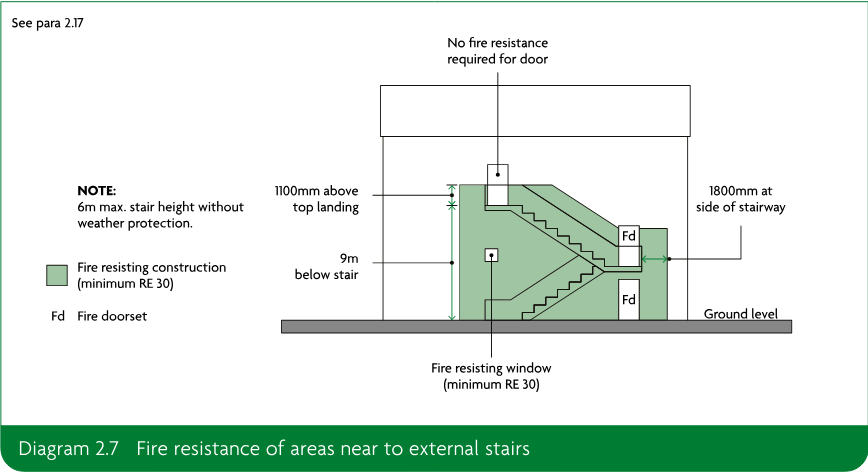
Page 17Replace Diagram 2.7 with the following.
Section 3: Means of escape – flats
#Source page 5
Page 21Replace paragraph 3.14 with the following.
3.14The internal arrangement of single storey or multi-storey flats should comply with paragraphs 3.15 to 3.17. Alternatively, the guidance in paragraphs 3.18 to 3.22 may be followed.
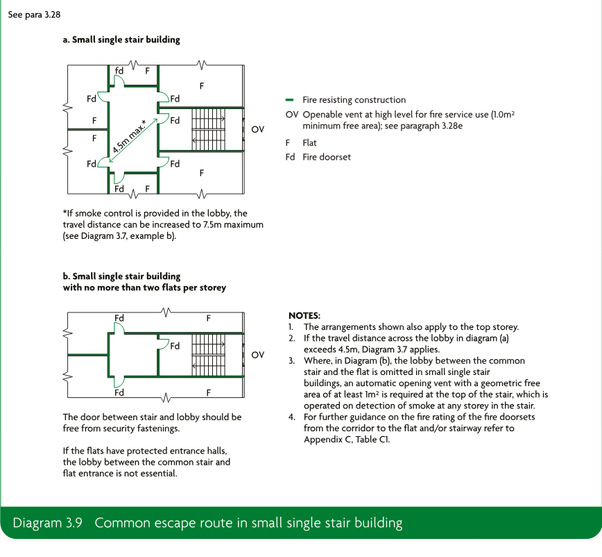
Where a flat is accessed via the common parts of a block of flats it may be necessary to provide a protected entrance hall to meet the provisions of paragraph 3.28 and Diagram 3.9.
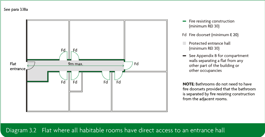
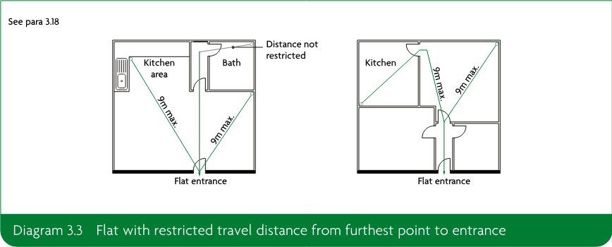
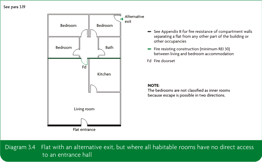
Page 22Paragraph 3.18, replace sub-paragraph (c) with the following.
c.Provide an alternative exit from the flat complying with paragraph 3.19.
Replace Diagram 3.2 with the following.
Page 6
#Source page 6
Replace Diagram 3.3 with the following.
Page 23Replace Diagram 3.4 with the following.
Paragraph 3.21, replace sub-paragraph (c) with the following.
c.Approach 3 – provide a protected stairway plus a sprinkler system in accordance with Appendix E (smoke alarms should also be provided in accordance with Section 1).
Page 7
#Source page 7
Page 24Replace Diagram 3.5 with the following.
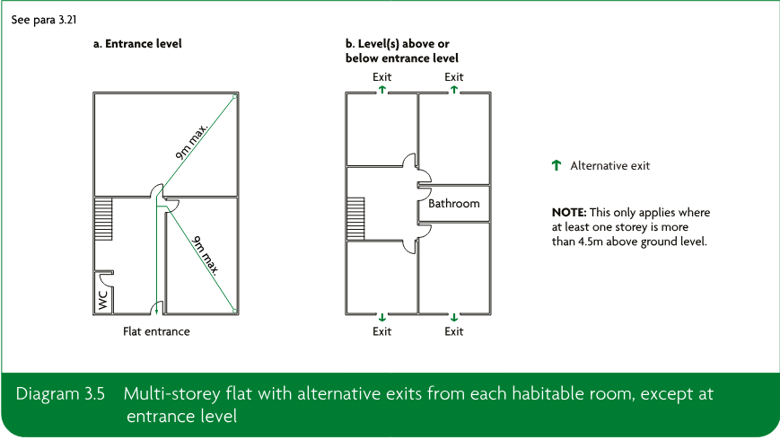
Replace Diagram 3.6 with the following.
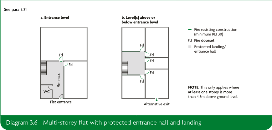
Page 26
#Source page 8
Replace paragraph 3.25 with the following.
3.25The following paragraphs deal with means of escape from the entrance doors of flats to a final exit. They do not apply to flats with a top storey that is a maximum of 4.5m above ground level (designed in accordance with paragraphs 3.15 to 3.17).
Reference should also be made to the following.
a.Requirement B3 regarding compartment walls and protected shafts.
b.Requirement B5 regarding access for the fire and rescue service.
Page 27
Replace Diagram 3.7 with the following.
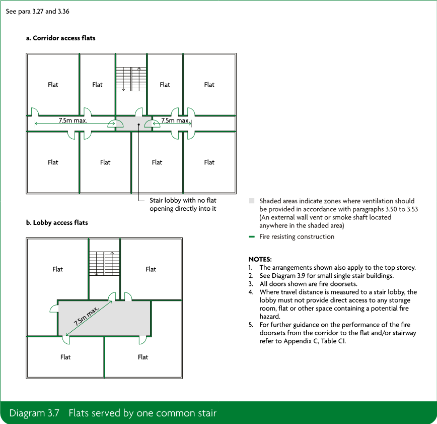
Page 28
#Source page 9
Replace Diagram 3.8 with the following.
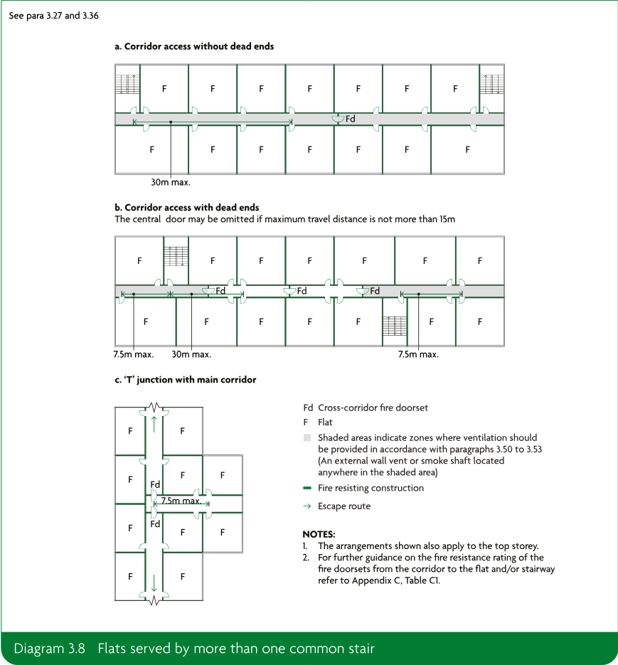
Page 29
#Source page 10
Replace Diagram 3.9 with the following.
Page 30
Replace paragraph 3.41 with the following.
3.41Except for two storey blocks of flats, all escape routes should have adequate artificial lighting. If the mains electricity power supply fails, escape lighting should illuminate the route (including external escape routes).
Page 32
Paragraph 3.51, replace sub-paragraph (b)(iii) with the following.
iii.The smoke shaft should be constructed from a class A1 material. All vents should either be a smoke leakage (Sₐ) rated fire doorset (see Appendix C, Table C1, item 2.e for minimum fire resistance) or fitted with a smoke control damper achieving the same period of fire resistance and designed to operate as described below. The shaft should be vertical from base to head, with a maximum of 4m at a maximum inclined angle of 30 degrees.
Page 33
#Source page 11
Replace paragraph 3.62 with the following.
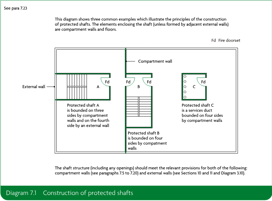
3.62Every common stair should be a protected stairway. Where the protected stairway passes from one compartment to another, it should be within a protected shaft.
Page 34
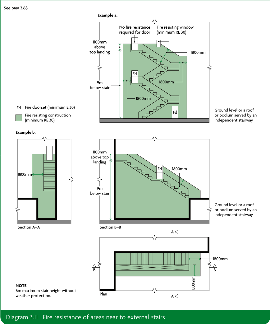
Paragraph 3.66, replace sub-paragraph (b) with the following.
b.The stair meets the provisions in paragraph 3.68.
Page 35
Replace Diagram 3.11 with the following.
Section 4: Wall and ceiling linings
#Source page 12
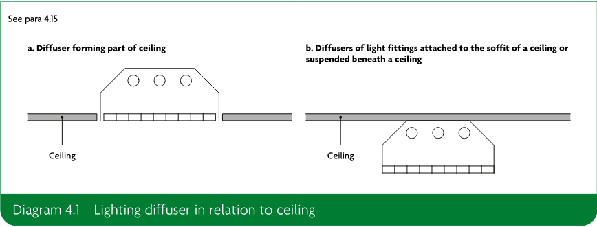
Page 45Replace Diagram 4.1 with the following.
Section 5: Internal fire spread – dwellinghouses
Page 50Replace paragraph 5.1 with the following.
5.1Elements of structure such as structural frames, beams, columns, loadbearing walls (internal and external), floor structures and gallery structures should have, as a minimum, the fire resistance given in Appendix B, Table B3.
Section 6: Loadbearing elements of structures – flats
Page 57Replace the section title with the following.
Section 6: Loadbearing elements of structure – flats
Replace paragraph 6.1 with the following.
6.1Elements of structure such as structural frames, beams, columns, loadbearing walls (internal and external), floor structures and gallery structures should have, as a minimum, the fire resistance given in Appendix B, Table B3.
Section 7: Compartmentation/sprinklers – flats
#Source page 13
Page 59Replace paragraph 7.1 with the following.
7.1All of the following should be provided as compartment walls and compartment floors and should have, as a minimum, the fire resistance given in Appendix B, Table B3.
a.Any floor (unless it is within a flat, i.e. between one storey and another within one individual dwelling).
b.Any wall separating a flat from another part of the building.
c.Any wall enclosing a refuse storage chamber.
d.Any wall common to two or more buildings.
Page 62Replace Diagram 7.1 with the following.
Section 8: Cavities – flats
#Source page 14
Page 63Replace Diagram 7.2 with the following.
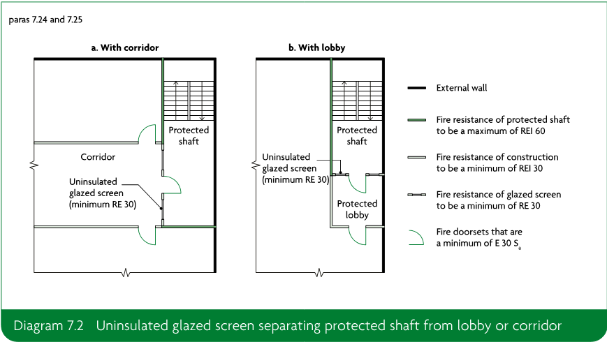
Section 8: Cavities – flats
Page 65Replace subheading before paragraph 8.3 with the following.
Junctions and edges of cavities
Page 67Replace Diagram 8.3 with the following.
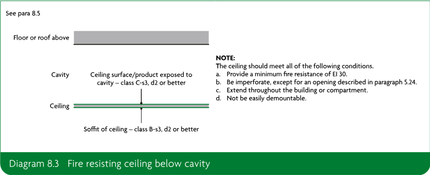
Page 68Replace paragraph 8.9 with the following.
8.9Cavity barriers should meet the requirements set out in paragraphs 5.21 to 5.24.
Section 9: Protection of openings and fire-stopping
#Source page 15
Page 69Replace paragraph 9.1 with the following.
9.1Every joint, imperfect fit and opening for services through a fire-separating element should be sealed with fire-stopping to ensure that the fire resistance of the element is not impaired. Fire-stopping delays the spread of fire and, generally, the spread of smoke as well.
Page 70Replace Diagram 9.2 with the following.
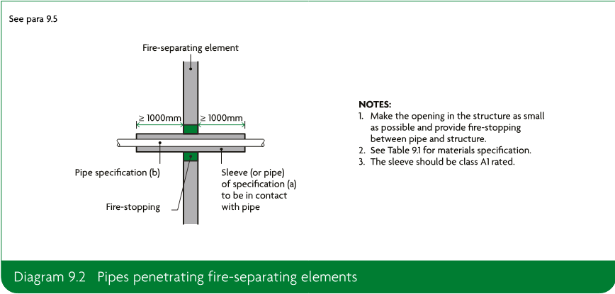
Page 71In Table 9.1 Maximum nominal internal diameter of pipes passing through a compartment wall/floor, replace the table title with the following.
Table 9.1 Maximum nominal internal diameter of pipes passing through a fire-separating element
Page 72Replace paragraph 9.12 with the following.
9.12If air handling ducts pass through fire-separating elements, the fire performance of the elements should be maintained using one or more of the following four methods. In most ductwork systems, a combination of the four methods is best.
a.Method 1 – thermally activated fire dampers.
b.Method 2 – fire resisting enclosures.
c.Method 3 – protection using fire resisting ductwork.
d.Method 4 – automatically activated fire and smoke dampers triggered by smoke detectors.
Requirement B4: External fire spread
#Source page 16
Page 76 Replace the requirement text with the following.
| Requirement | Limits on application |
|---|---|
| External fire spread B4. (1) The external walls of the building shall adequately resist the spread of fire over the walls and from one building to another having regard to the height, use and position of the building. (2) The roof of the building shall adequately resist the spread of fire over the roof and from one building to another, having regard to the use and position of the building. | |
| Regulation 7 – Materials and workmanship (1) Building work shall be carried out— (a) with adequate and proper materials which— (i) are appropriate for the circumstances in which they are used, (ii) are adequately mixed or prepared, and (iii) are applied, used or fixed so as adequately to perform the functions for which they are designed; and (b) in a workmanlike manner. (1A) Building work shall be carried out so that relevant metal composite material does not become part of an external wall, or specified attachment, of any building. (2) Subject to paragraph (3), building work shall be carried out so that materials which become part of an external wall, or specified attachment, of a relevant building are of European Classification A2-s1, d0 or A1 (classified in accordance with the reaction to fire classification). |
Page 17
#Source page 17
Section 10: Resisting fire spread over external walls
#Source page 18
Replace Section 10 with the following.
Section 10: Resisting fire spread over external walls
Introduction
10.1The external wall of a building should not provide a medium for fire spread if that is likely to be a risk to health and safety. Combustible materials and cavities in external walls and attachments to them can present such a risk, particularly in tall buildings. The guidance in this section is designed to reduce the risk of fire spread as well as the risk of ignition from flames coming from adjacent buildings.
Fire resistance
10.2This section provides guidance on resisting fire spread over external walls; however, it does not deal with fire resistance of external walls. An external wall may need fire resistance to meet the provisions of Section 3 (Means of escape – flats), Section 6 (Loadbearing elements of structure – flats), Section 11 (Resisting fire spread from one building to another) or Section 15 (Access to buildings for firefighting personnel – flats).
Combustibility of external walls
10.3The external walls of buildings other than those described in regulation 7(4) of the Building Regulations should achieve either of the following.
a.Follow the provisions given in paragraphs 10.5 to 10.9, which provide guidance on all of the following.
i.External surfaces.
ii.Materials and products.
iii.Cavities and cavity barriers.
b.Meet the performance criteria given in BRE report BR 135 for external walls using full-scale test data from BS 8414-1 or BS 8414-2.
10.4In relation to buildings of any height or use, consideration should be given to the choice of materials (including their extent and arrangement) used for the external wall, or attachments to the wall (e.g. balconies, etc.), to reduce the risk of fire spread over the wall.
External surfaces
#Source page 19
10.5The external surfaces (i.e. outermost external material) of external walls should comply with the provisions in Table 10.1. The provisions in Table 10.1 apply to each wall individually in relation to its proximity to the relevant boundary.
| Building type | Building height | Less than 1000mm from the relevant boundary | 1000mm or more from the relevant boundary |
|---|---|---|---|
| ‘Relevant buildings’ as defined in regulation 7(4) (see paragraph 10.14) | Class A2-s1, d0(1) or better | Class A2-s1, d0(1) or better | |
| All ‘residential’ purpose groups (purpose groups 1 and 2) | More than 11m | Class A2-s1, d0(2) or better | Class A2-s1, d0(2) or better |
| 11m or less | Class B-s3, d2(2) or better | No provisions | |
| Assembly and recreation | More than 18m | Class B-s3, d2(2) or better | From ground level to 18m: class C-s3, d2(3) or better From 18m in height and above: class B-s3, d2(2) or better |
| 18m or less | Class B-s3, d2(2) or better | Up to 10m above ground level: class C-s3, d2(3) or better Up to 10m above a roof or any part of the building to which the public have access: class C-s3, d2(3) or better(4) From 10m in height and above: no minimum performance | |
| Any other building | More than 18m | Class B-s3, d2(2) or better | From ground level to 18m: class C-s3, d2(3) or better From 18m in height and above: class B-s3, d2(2) or better |
| 18m or less | Class B-s3, d2(2) or better | No provisions |
NOTES:
In all cases all the following provisions apply.
• Regulation 7(1A) prohibits the use of relevant metal composite materials in the external walls of all buildings of any height (see paragraphs 10.11 and 10.12).
• The advice in paragraph 10.4 should always be followed.
In addition to the provisions within this table, buildings with a storey 18m or more above ground level should also meet the provisions of paragraph 10.6.
In addition to the provisions within this table, buildings with a storey 11m or more above ground level should also meet the provisions of paragraph 10.7.
1. The restrictions for these buildings apply to all the materials used in the external wall and specified attachments (see paragraphs 10.13 to 10.16 for further guidance).
2. Profiled or flat steel sheet at least 0.5mm thick with an organic coating of no more than 0.2mm thickness is also acceptable.
3. Timber cladding at least 9mm thick is also acceptable.
4. 10m is measured from the top surface of the roof.
Materials and products
#Source page 20
10.6In a building with a storey 18m or more in height (see Diagram D6 in Appendix D) any insulation product, filler material (such as the core materials of metal composite panels, sandwich panels and window spandrel panels but not including gaskets, sealants and similar) etc. used in the construction of an external wall should be class A2-s3, d2 or better (see Appendix B). This restriction does not apply to masonry cavity wall construction which complies with Diagram 8.2 in Section 8. Where regulation 7(2) applies, that regulation prevails over all the provisions in this paragraph.
10.7In buildings that include a ‘residential’ purpose (purpose groups 1 and 2) with a storey 11m or more in height (see Diagram D6 in Appendix D) any insulation product, filler material (such as the core materials of metal composite panels, sandwich panels and window spandrel panels but not including gaskets, sealants and similar) etc. used in the construction of an external wall should be class A2-s1, d0 or better (see Appendix B). This restriction does not apply to masonry cavity wall construction which complies with Diagram 8.2 in Section 8. Where regulation 7(2) applies, that regulation prevails over all the provisions in this paragraph.
10.8Best practice guidance for green walls (also called living walls) can be found in Fire Performance of Green Roofs and Walls, published by the Department for Communities and Local Government. Where regulation 7(2) applies, that regulation prevails over all the provisions in this paragraph.
Cavities and cavity barriers
10.9Cavity barriers should be provided in accordance with Section 5 in dwellinghouses and Section 8 in flats.
Balconies
10.10In buildings that include a ‘residential’ purpose (purpose groups 1 and 2) with a storey 11m or more in height (see Diagram D6 in Appendix D) balconies should meet either of the following conditions.
a.Only contain materials achieving class A1 or A2-s1, d0, except for any of the following.
i.Cavity trays when used between two leaves of masonry.
ii.Intumescent and fire-stopping materials where the inclusion of the materials is necessary to meet the requirements of Part B of Schedule 1 to the Building Regulations 2010.
iii.Membranes.
iv.Seals, gaskets, fixings, sealants and backer rods.
v.Thermal break materials where the inclusion of the materials is necessary to meet the thermal bridging requirements of Part L of Schedule 1 to the Building Regulations 2010.
vi.Any material achieving class A1fl or A2fl-s1 when it forms the top horizontal floor layer of a balcony and is provided with an imperforate substrate under it which extends to the full size of the class A1fl or A2fl-s1 material.
vii.Electrical installations.
viii.Fibre optic cables.
Metal composite materials
#Source page 21
b.Achieve both of the following conditions.
i.Have an imperforate soffit which extends to the full area of the balcony, achieves a minimum REI 30 rating and is constructed of materials achieving class A2-s1, d0 or better.
ii.Materials achieving class B-s1, d0 or worse extending beyond the boundary of a single compartment should include a band of material rated class A2-s1, d0 or better, a minimum of 300mm in width centred on that boundary line.
Where regulation 7(2) applies, that regulation prevails over all the provisions in this paragraph.
Metal composite materials
10.11Regulation 7(1A) prohibits the use of relevant metal composite materials in the external walls of all buildings of any height.
10.12Relevant metal composite materials are defined (in regulation 2(6)(c)) as any panel or sheet, having a thickness of no more than 10mm which is composed of a number of layers two or more of which are made of metal, alloy or metal compound and one or more of which is a substantial layer made of a material having a gross calorific value of more than 35MJ/kg when tested in accordance with BS EN ISO 1716. A substantial layer is defined as a layer which is at least 1mm thick or has a mass per unit area of at least 1kg/m².
Regulation 7(2) and requirement B4
Materials
10.13Regulation 7(1)(a) requires that materials used in building work are appropriate for the circumstances in which they are used. Regulation 7(2) sets requirements in respect of external walls and specified attachments in relevant buildings.
10.14Regulation 7(2) applies to any building with a storey at least 18m above ground level (as measured in accordance with Diagram D6 in Appendix D) and which contains one or more dwellings; an institution; or a room for residential purposes. It requires that all materials which become part of an external wall or specified attachment achieve class A2-s1, d0 or class A1 in accordance with BS EN 13501-1, other than those exempted by regulation 7(3).
10.15External walls and specified attachments are defined in regulation 2(6) and these definitions include any parts of the external wall as well as balconies, solar panels and solar shading.
10.16Regulation 7(3) provides an exemption for certain components found in external walls and specified attachments.
Material change of use
#Source page 22
10.17Regulations 5(k) and 6(3) provide that, where the use of a building is changed such that the building becomes a building described in regulation 7(4), the construction of the external walls, and specified attachments, must be investigated and, where necessary, work must be carried out to ensure they only contain materials achieving class A2-s1, d0 or class A1, other than those exempted by regulation 7(3).
Solar shading devices
10.18Regulation 7(2) requires that the curtain and or slats of solar shading devices in a relevant building (as defined in regulation 7(4)) achieve class A1 or A2-s1, d0. The curtain of solar shading devices cannot be classified as a membrane in accordance with regulation 7(3).
10.19Solar shading devices installed up to 4.5m above ground level are not required to meet the requirements of regulation 7(2).
Additional considerations
10.20The provisions of regulation 7 apply in addition to requirement B4. Therefore, for buildings described in regulation 7(4), the potential impact of any products incorporated into or onto the external walls and specified attachments should be carefully considered with regard to their number, size, orientation and position.
10.21Particular attention is drawn to the following points.
a.Membranes used as part of the external wall construction above ground level should achieve a minimum of class B-s3, d0. Roofing membranes do not need to achieve a minimum of class A2-s1, d0 when used as part of a roof connecting to an external wall.
b.Internal linings should comply with the guidance provided in Section 4.
c.Any part of a roof should achieve the minimum performance as detailed in Section 12.
d.As per regulation 7(3), window frames and glass (including laminated glass) are exempted from regulation 7(2). Window spandrel panels and infill panels must comply with regulation 7(2).
e.Thermal breaks are small elements used as part of the external wall construction to restrict thermal bridging. There is no minimum performance for these materials. However, they should not span two compartments and should be limited in size to the minimum required to restrict the thermal bridging (the principal insulation layer is not to be regarded as a thermal break).
f.Regulation 7(2) only applies to specified attachments. Shop front signs and similar attachments are not covered by the requirements of regulation 7(2), although attention is drawn to paragraph 10.21g.
g.While regulation 7(2) applies to materials which become part of an external wall or specified attachment, consideration should be given to other attachments to the wall which could impact on the risk of fire spread over the wall.
h.Any material achieving class A1fl or A2fl-s1 in accordance with BS EN 13501-1 is exempted when it meets both of the following conditions.
i.It forms the top horizontal floor layer of a balcony.
ii.It is provided with an imperforate substrate under it which extends to the full size of the class A1fl or A2fl-s1 material.
Section 11: Resisting fire spread from one building to another
#Source page 23
Page 86Replace paragraph 11.7 with the following.
11.7Where a fire resisting external wall has an external surface material that is worse than class B-s3, d2 and is more than 1mm thick, that part of the wall should be classified as an unprotected area equating to half its area (Diagram 11.4).
Replace paragraph 11.10 with the following.
11.10Exclude external walls of stairways in a protected shaft when assessing unprotected areas (see Diagram 11.5).
Page 89Replace paragraph 11.16 with the following.
11.16Two simple methods are given for calculating the acceptable amount of unprotected area in an external wall that is a minimum of 1000mm from any point on the relevant boundary. More precise methods are described in BRE report BR 187 and may be used instead. When using BR 187 the following radiation intensity at each unprotected area should be assumed.
a.84kW/m² if the purpose group of the building is ‘residential’ (purpose groups 1 or 2), ‘office’ (purpose group 3) or ‘assembly and recreation’ (purpose group 5) or if the building is an open-sided multi-storey car park (purpose group 7(b)).
b.168kW/m² if the purpose group of the building is ‘shop and commercial’ (purpose group 4), ‘industrial’ (purpose group 6) or ‘storage and other non-residential’ (purpose group 7(a)).
Section 12: Resisting fire spread over roof coverings
Page 93In Table 12.1 Limitations on roof coverings, replace note 3 with the following.
3.Acceptable on buildings not listed in (2) if both of the following apply.
a.Part of the roof has a maximum area of 3m² and is a minimum of 1500mm from any similar part.
b.The roof between the parts is covered with a material rated class A2-s3, d2 or better.
Requirement B5: Access and facilities for the fire service
#Source page 24
Intention
Page 96Insert new sub-paragraph (e).
e.A facility to store building information for firefighters to complete their tasks.
Section 13: Vehicle access
Page 97Replace paragraph 13.1 with the following.
13.1For dwellinghouses, access for a pumping appliance should be provided to within 45m of all points inside the dwellinghouse.
Every elevation to which vehicle access is provided should have a suitable door(s), not less than 750mm wide, giving access to the interior of the building.
Replace paragraph 13.2 with the following.
13.2For flats, either of the following provisions should be made.
a.Provide access for a pumping appliance to within 45m of all points inside each flat of a block, measured along the route of the hose. Every elevation to which vehicle access is provided should have a suitable door(s), not less than 750mm wide, giving access to the interior of the building. Door(s) should be provided such that there is no more than 60m between each door and/or the end of that elevation (e.g. a 150m elevation would need at least two doors).
b.Provide fire mains in accordance with paragraphs 13.5 and 13.6.
Page 98Paragraph 13.5, replace sub-paragraph (b) with the following.
b.The fire main inlet connection point should be visible from the parking position of the appliance, and meet the provisions in Section 8 of BS 9990.
Section 15: Access to buildings for firefighting personnel – flats
#Source page 25
Page 104Replace paragraph 15.5 with the following.
15.5In buildings where a firefighting shaft is required, a minimum of two firefighting shafts should be provided in either of the following situations.
a.A building that has both of the following.
i.A storey with a floor area of 900m² or more.
ii.A storey 18m or more above the fire and rescue service vehicle access level.
b.A building with a basement storey which is more than 900m².
Page 106Insert new headings and paragraphs after paragraph 15.16 as follows.
Evacuation alert systems
15.17In blocks of flats (purpose group 1(a)) with a top storey over 18m above ground level (see Diagram D6 in Appendix D) an evacuation alert system should be provided in accordance with BS 8629.
Secure information boxes
15.18A secure information box provides a secure facility to store information about a building for use by the fire service during an incident.
15.19Blocks of flats (purpose group 1(a)) with a top storey more than 11m above ground level (see Diagram D6 in Appendix D) should be provided with a secure information box.
15.20The box should meet all of the following conditions.
a.Sized to accommodate all necessary information.
b.Easily located and identified by firefighters.
c.Secured to resist unauthorised access but readily accessible by firefighters.
d.Protected from the weather.
15.21Best practice guidance can be found in Sections 2 to 4 of the Code of Practice for the Provision of Premises Information Boxes in Residential Buildings published by the Fire Industry Association (FIA).
Section 16: Venting of heat and smoke from basements – flats
#Source page 26
Page 108 Replace Diagram 16.1 with the following.
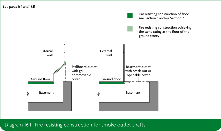
Appendix A: Key terms
Page 115 Insert the following entry between the definitions of Corridor access and Dead end.
Curtain Part of a solar shading device which is set in motion by the operating system and fulfils the purpose of a blind, awning or shutter.
Page 118 Insert the following entry between the definitions of Site and ***Specified attachment**.
Solar shading device A device attached to an external wall for reducing heat gain or controlling visible light within a building by shading or deflecting sunlight.
Appendix B: Performance of materials, products and structures
#Source page 27
Page 120Replace paragraph B4 with the following.
B4Where it is proposed to assess the classification of a product or system in lieu of carrying out a specific test (as in paragraph B1c), this should be done in accordance with the relevant standard for extended application for the test in question and should include details of the test evidence that has been used to support the assessment.
For performance classifications where there is no specific standard for extended application, assessment reports should be produced in accordance with the principles of BS EN 15725 and should include details of the test evidence that has been used to support the assessment. Further information on best practice is provided in the Passive Fire Protection Forum’s Guide to Undertaking Technical Assessments of the Fire Performance of Construction Products Based on Fire Test Evidence.
Pages 125 to 128Replace paragraph B25 with the following.
B25This document uses the European classification system for fire resistance set out in BS EN 13501-2 to 4; however, there may be some products lawfully on the market using the classification system set out in previous editions. In those situations the alternative classifications given in Table B3 can be used.
In Table B3 Specific provisions of the test for fire resistance of elements of structure, etc., replace rows as follows.
1.Replace row 2 with the following.
| 2. Loadbearing wall (for a wall which is also described in any of the following items, the more onerous guidance should be applied). | R see Table B4 | See Table B4 | Not applicable | Not applicable | Each side separately |
2.Replace row 3b with the following.
| b. in upper storey of two storey dwellinghouse (but not over garage or basement) | R 30 and EI 15 | 30 min | 15 min | 15 min | From underside⁽⁵⁾ |
Appendix D: Methods of measurement
#Source page 28
3.Replace row 5b with the following.
| b. any part a minimum of 1000mm from the relevant boundary(6) | RE see Table B4 and I 15 | See Table B4 | See Table B4 | 15 min | From inside the building |
4.Replace row 8 with the following.
| 8. Protected shafts Excluding any firefighting shaft: a. any glazing described in Section 7 diagram 7.2 | E 30 | Not applicable | 30 min | No provision(8) | Each side separately |
| b. any other part between the shaft and a protected lobby/corridor described in Section 7 diagram 7.2 | REI 30 | 30 min | 30 min | 30 min | Each side separately |
| c. any part not described in (a) or (b) above. | REI see Table B4 | See Table B4 | See Table B4 | See Table B4 | Each side separately |
5.Replace row 17 with the following.
| 17. Cavity barrier | E 30 and I 15 | Not applicable | 30 min | 15 min | Each side separately |
Appendix D: Methods of measurement
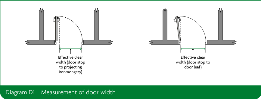
Page 141 Replace Diagram D1 with the following.
The Building Regulations
#Source page 29
Notification of work
Page ivReplace sub-paragraph (b) with the following.
b.It is work exempted from the need to notify by regulation 12(6)(a) of, or Schedule 4 to, the Building Regulations.
Section 0: Approved Document B: Fire safety – buildings other than dwellings
Page 5In Table 0.1 Classification of purpose groups, replace the ‘Residential (institutional) 2(a)’ row with the following.
| Purpose group | Sub-group | Description |
|---|---|---|
| Residential (institutional) | 2(a) | Hospital, home, school or other similar establishment, where people sleep on the premises. The building may be either of the following: • Living accommodation for, or accommodation for the treatment, care or maintenance of, either: – disabled people with a range of impairments including physical, sensory and cognitive impairments, or mental health conditions – people under the age of 5 years. • A place of lawful detention. |
Section 1: Fire detection and alarm systems
#Source page 30
Page 11 Insert new heading and paragraph after paragraph 1.17 as follows.
Student accommodation
1.18In student residences that are designed and occupied as a block of flats, separate automatic detection should be provided in each self-contained flat where all of the following apply.
a.A group of up to six students shares the flat.
b.Each flat has its own entrance door.
c.The compartmentation principles for flats in Section 7 of Approved Document B Volume 1 have been followed.
Where a total evacuation strategy is adopted, the alarm system should follow the guidance elsewhere in this section.
Section 2: Design for horizontal escape
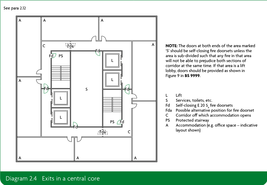
Page 17 Replace Diagram 2.4 with the following.
Page 31
#Source page 31
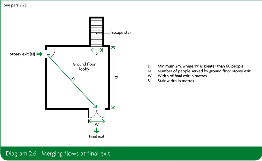
Page 20 Replace Diagram 2.6 with the following.
Page 32
#Source page 32
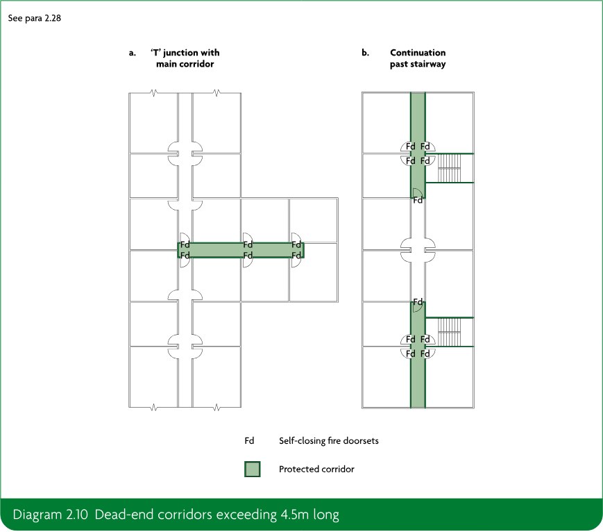
Page 24 Replace Diagram 2.10 with the following.
Page 33
#Source page 33
Page 26 Replace Diagram 2.11 with the following.
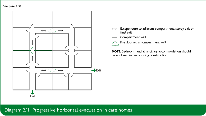
Section 3: Design for vertical escape
#Source page 34
Page 30 Replace Diagram 3.1 with the following.
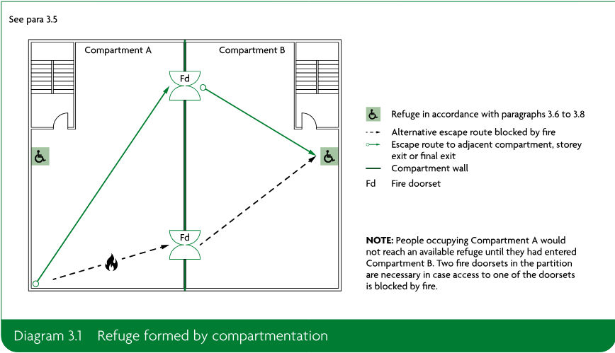
Page 35 Replace paragraph 3.20 with the following.
3.20Phased evacuation in buildings with a storey over 30m in height introduces the potential for escaping people to impede firefighters entering and operating within the building. This can be addressed by consulting with the fire and rescue service about special management procedures.
In very tall buildings, typically with a storey over 45m in height, physical measures may need to be incorporated, such as by discounting a stair.
Paragraph 3.21, replace sub-paragraph (d) with the following.
d.If there is a storey over 30m above ground level, the building should be protected throughout by an automatic sprinkler system in accordance with Appendix E.
Page 36 Replace paragraph 3.23 with the following.
3.23Every internal escape stair should be a protected stairway (within a fire resisting enclosure). If it is also a protected shaft (i.e. it passes from one compartment to another) or firefighting shaft, additional guidance in Sections 8 and 17 applies.
There is one exception: an unprotected stair (e.g. an accommodation stair) may form part of an internal route to a storey exit or final exit, provided that the distance of travel and the number of people involved are very limited. For example, small premises (Section 4) and raised storage areas (see paragraphs 7.6 and 7.7).
Page 35
#Source page 35
Page 39 Replace Diagram 3.4 with the following.
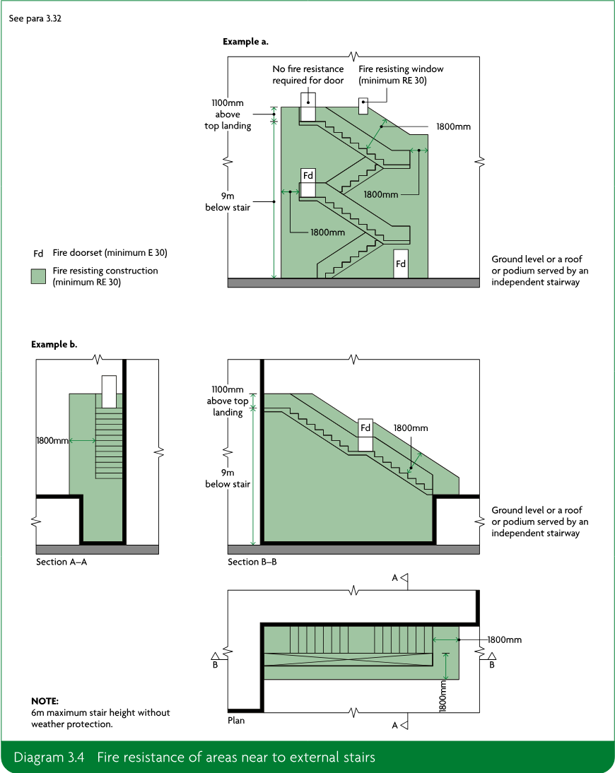
Section 5: General provisions
#Source page 36
In Table 5.1 Provisions for escape lighting, replace the ‘Residential’ row with the following.
| Residential | All common escape routes(1), except in two storey blocks of flats |
Section 6: Wall and ceiling linings
Replace Diagram 6.1 with the following.
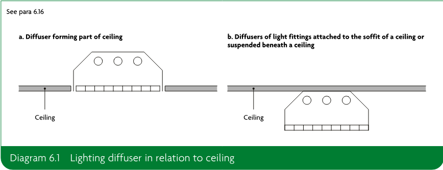
Section 7: Loadbearing elements of structures
Replace the section title with the following.
Section 7: Loadbearing elements of structure
Replace paragraph 7.1 with the following.
7.1Elements of structure such as structural frames, beams, columns, loadbearing walls (internal and external), floor structures and gallery structures should have, as a minimum, the fire resistance given in Appendix B, Table B3.
Section 8: Compartmentation/sprinklers
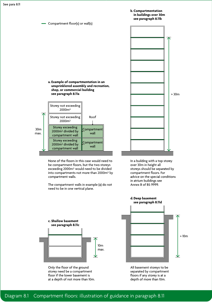
Replace Diagram 8.1 with the following.
Page 37
#Source page 37
Page 38
#Source page 38
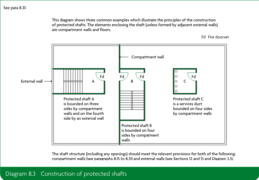
Page 73Replace Diagram 8.3 with the following.
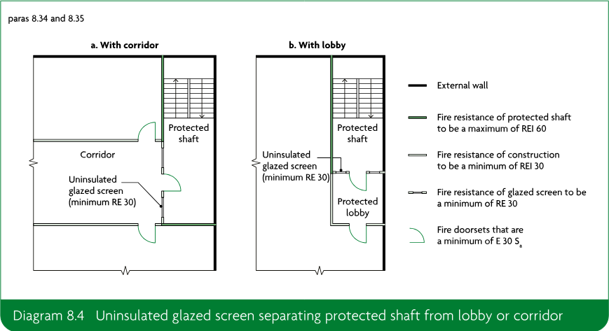
Page 74Replace Diagram 8.4 with the following.
Section 9: Cavities
#Source page 39
Page 77Replace subheading before paragraph 9.3 with the following.
Junctions and edges of cavities
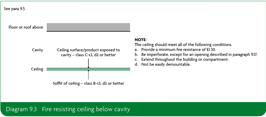
Page 78Replace Diagram 9.3 with the following.
Page 80Replace the first sentence of paragraph 9.12 with the following. If the undivided area exceeds 40m in any direction, there is no limit to its size if all of the following conditions are met.
Section 10: Protection of openings and fire-stopping
Page 82Replace paragraph 10.1 with the following.
10.1Every joint, imperfect fit and opening for services through a fire-separating element should be sealed with fire-stopping to ensure the fire resistance of the element is not impaired. Fire-stopping delays the spread of fire and, generally, the spread of smoke as well.
Page 40
#Source page 40
Page 83 Replace Diagram 10.1 with the following.
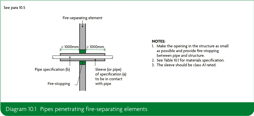
In Table 10.1 Maximum nominal internal diameter of pipes passing through a compartment wall/floor, replace the table title with the following.
Table 10.1 Maximum nominal internal diameter of pipes passing through a fire-separating element
Page 84 Replace paragraph 10.12 with the following.
10.12If air handling ducts pass through fire-separating elements, the fire performance of the elements should be maintained using one or more of the following four methods. In most ductwork systems, a combination of the four methods is best.
a.Method 1 – thermally activated fire dampers.
b.Method 2 – fire resisting enclosures.
c.Method 3 – protection using fire resisting ductwork.
d.Method 4 – automatically activated fire and smoke dampers triggered by smoke detectors.
Section 11: Special provisions for car parks
#Source page 41
Page 89Paragraph 11.2, replace sub-paragraph (b) with the following.
b.Each storey is naturally ventilated by permanent openings at each car parking level. The aggregate vent area is a minimum of 1/20 of that level’s floor area, at least half of which is provided equally by two opposite walls (1/80 on each side). The remaining free area can be distributed wherever possible.
Requirement B4: External fire spread
Pages 91 and 92Replace the requirement text with the following.
| Requirement | Limits on application |
|---|---|
| External fire spread B4. (1) The external walls of the building shall adequately resist the spread of fire over the walls and from one building to another having regard to the height, use and position of the buildings. | |
| (2) The roof of the building shall adequately resist the spread of fire over the roof and from one building to another, having regard to the use and position of the building. |
Regulation
Regulation 7 – Materials and workmanship
(1)Building work shall be carried out—
(a)with adequate and proper materials which—
(i)are appropriate for the circumstances in which they are used,
(ii)are adequately mixed or prepared, and
(iii)are applied, used or fixed so as adequately to perform the functions for which they are designed; and
(b)in a workmanlike manner.
(1A)Building work shall be carried out so that relevant metal composite material does not become part of an external wall, or specified attachment, of any building.
Page 42
#Source page 42
Regulation continued
(2)Subject to paragraph (3), building work shall be carried out so that materials which become part of an external wall, or specified attachment, of a relevant building are of European Classification A2-s1, d0 or A1 (classified in accordance with the reaction to fire classification).
(3)Paragraph (2) does not apply to—
(a)cavity trays when used between two leaves of masonry;
(b)any part of a roof (other than any part of a roof which falls within paragraph (iv) of regulation 2(6)) if that part is connected to an external wall;
(c)door frames and doors;
(d)electrical installations;
(da)fibre optic cables;
(e)insulation and water proofing materials used below ground level or up to 300mm above that level;
(f)intumescent and fire stopping materials where the inclusion of the materials is necessary to meet the requirements of Part B of Schedule 1;
(g)membranes;
(h)seals, gaskets, fixings, sealants and backer rods;
(ha)components associated with a solar shading device, excluding components whose primary function is to provide shade or deflect sunlight, such as the awning, curtain or slats;
(i)thermal break materials where the inclusion of the materials is necessary to meet the thermal bridging requirements of Part L of Schedule 1;
(j)window frames and glass; or
(k)materials which form the top horizontal floor layer of a balcony which are of European Classification A1fl or A2fl-s1 (classified in accordance with the reaction to fire classification) provided that the entire layer has an imperforate substrate under it.
(4)In this regulation—
(a)a “relevant building” means a building with a storey (not including roof-top plant areas or any storey consisting exclusively of plant rooms) at least 18 metres above ground level and which—
(i)contains one or more dwellings;
(ii)contains an institution; or
(iii)contains a room for residential purposes; and
(b)“above ground level” in relation to a storey means above ground level when measured from the lowest ground level adjoining the outside of a building to the top of the floor surface of the storey.
Section 12: Resisting fire spread over external walls
#Source page 43
Pages 94 to 97Replace Section 12 with the following.
Section 12: Resisting fire spread over external walls
Introduction
12.1The external wall of a building should not provide a medium for fire spread if that is likely to be a risk to health and safety. Combustible materials and cavities in external walls and attachments to them can present such a risk, particularly in tall buildings. The guidance in this section is designed to reduce the risk of fire spread as well as the risk of ignition from flames coming from adjacent buildings.
Fire resistance
12.2This section provides guidance on resisting fire spread over external walls; however, it does not deal with fire resistance of external walls. An external wall may need fire resistance to meet the provisions of Section 3 (Design for vertical escape), Section 7 (Loadbearing elements of structure), Section 13 (Resisting fire spread from one building to another) or Section 17 (Access to buildings for firefighting personnel).
Combustibility of external walls
12.3The external walls of buildings other than those described in regulation 7(4) of the Building Regulations should achieve either of the following.
a.Follow the provisions given in paragraphs 12.5 to 12.10, which provide guidance on all of the following.
i.External surfaces.
ii.Materials and products.
iii.Cavities and cavity barriers.
b.Meet the performance criteria given in BRE report BR 135 for external walls using full-scale test data from BS 8414-1 or BS 8414-2.
12.4In relation to buildings of any height or use, consideration should be given to the choice of materials (including their extent and arrangement) used for the external wall, or attachments to the wall (e.g. balconies, etc.), to reduce the risk of fire spread over the wall.
External surfaces
#Source page 44
12.5The external surfaces (i.e. outermost external material) of external walls should comply with the provisions in Table 12.1. The provisions in Table 12.1 apply to each wall individually in relation to its proximity to the relevant boundary.
| Building type | Building height | Less than 1000mm from the relevant boundary | 1000mm or more from the relevant boundary |
|---|---|---|---|
| ‘Relevant buildings’ as defined in regulation 7(4) (see paragraph 12.15) | Class A2-s1, d0(1) or better | Class A2-s1, d0(1) or better | |
| All ‘residential’ purpose groups (purpose groups 1 and 2) | More than 11m | Class A2-s1, d0(2) or better | Class A2-s1, d0(2) or better |
| 11m or less | Class B-s3, d2(2) or better | No provisions | |
| Assembly and recreation | More than 18m | Class B-s3, d2(2) or better | From ground level to 18m: class C-s3, d2(3) or better From 18m in height and above: class B-s3, d2(2) or better |
| 18m or less | Class B-s3, d2(2) or better | Up to 10m above ground level: class C-s3, d2(3) or better Up to 10m above a roof or any part of the building to which the public have access: class C-s3, d2(3) or better(4) From 10m in height and above: no minimum performance | |
| Any other building | More than 18m | Class B-s3, d2(2) or better | From ground level to 18m: class C-s3, d2(3) or better From 18m in height and above: class B-s3, d2(2) or better |
| 18m or less | Class B-s3, d2(2) or better | No provisions |
NOTES:
In all cases all the following provisions apply.
• Regulation 7(1A) prohibits the use of relevant metal composite materials in the external walls of all buildings of any height (see paragraphs 12.12 and 12.13).
• The advice in paragraph 12.4 should always be followed.
In addition to the provisions within this table, buildings with a storey 18m or more above ground level should also meet the provisions of paragraph 12.6.
In addition to the provisions within this table, buildings with a storey 11m or more above ground level should also meet the provisions of paragraph 12.7.
1. The restrictions for these buildings apply to all the materials used in the external wall and specified attachments (see paragraphs 12.14 to 12.17 for further guidance).
2. Profiled or flat steel sheet at least 0.5 mm thick with an organic coating of no more than 0.2mm thickness is also acceptable.
3. Timber cladding at least 9mm thick is also acceptable.
4. 10m is measured from the top surface of the roof.
Materials and products
#Source page 45
12.6In a building with a storey 18m or more in height (see Diagram D6 in Appendix D) any insulation product, filler material (such as the core materials of metal composite panels, sandwich panels and window spandrel panels but not including gaskets, sealants and similar) etc. used in the construction of an external wall should be class A2-s3, d2 or better (see Appendix B). This restriction does not apply to masonry cavity wall construction which complies with Diagram 9.2 in Section 9. Where regulation 7(2) applies, that regulation prevails over all the provisions in this paragraph.
12.7In buildings that include a ‘residential’ purpose (purpose groups 1 and 2) with a storey 11m or more in height (see Diagram D6 in Appendix D) any insulation product, filler material (such as the core materials of metal composite panels, sandwich panels and window spandrel panels but not including gaskets, sealants and similar) etc. used in the construction of an external wall should be class A2-s1, d0 or better (see Appendix B). This restriction does not apply to masonry cavity wall construction which complies with Diagram 9.2 in Section 9. Where regulation 7(2) applies, that regulation prevails over all the provisions in this paragraph.
12.8Best practice guidance for green walls (also called living walls) can be found in Fire Performance of Green Roofs and Walls, published by the Department for Communities and Local Government. Where regulation 7(2) applies, that regulation prevails over all the provisions in this paragraph.
Cavities and cavity barriers
12.9Cavity barriers should be provided in accordance with Section 9.
12.10In the case of an external wall construction of a building which, by virtue of paragraph 9.10d (external cladding system with a masonry or concrete inner leaf), is not subject to the provisions of Table 9.1, the surfaces which face into cavities should also meet the provisions of Table 12.1 and provisions in Section 9, but where regulation 7(2) applies, that regulation prevails over the guidance provided in Table 12.1 and Section 9.
Balconies
12.11In buildings that include a ‘residential’ purpose (purpose groups 1 and 2) with a storey 11m or more in height (see Diagram D6 in Appendix D) balconies should meet either of the following conditions.
a.Only contain materials achieving class A1 or A2-s1, d0, except for any of the following.
i.Cavity trays when used between two leaves of masonry.
ii.Intumescent and fire-stopping materials where the inclusion of the materials is necessary to meet the requirements of Part B of Schedule 1 to the Building Regulations 2010.
iii.Membranes.
iv.Seals, gaskets, fixings, sealants and backer rods.
v.Thermal break materials where the inclusion of the materials is necessary to meet the thermal bridging requirements of Part L of Schedule 1 to the Building Regulations 2010.
Metal composite materials
#Source page 46
vi.Any material achieving class A1fl or A2fl-s1 when it forms the top horizontal floor layer of a balcony and is provided with an imperforate substrate under which extends to the full size of the class A1fl or A2fl-s1 material.
vii.Electrical installations.
viii.Fibre optic cables.
b.Achieve both of the following conditions.
i.Have an imperforate soffit which extends to the full area of the balcony, achieves a minimum REI 30 rating and is constructed of materials achieving class A2-s1, d0 or better.
ii.Materials achieving class B-s1, d0 or worse extending beyond the boundary of a single compartment should include a band of material rated class A2-s1, d0 or better, a minimum of 300mm in width centred on that boundary line.
Where regulation 7(2) applies, that regulation prevails over all the provisions in this paragraph.
Metal composite materials
12.12Regulation 7(1A) prohibits the use of relevant metal composite materials in the external walls of all buildings of any height.
12.13Relevant metal composite materials are defined (in regulation 2(6)(c)) as any panel or sheet, having a thickness of no more than 10mm which is composed of a number of layers two or more of which are made of metal, alloy or metal compound and one or more of which is a substantial layer made of a material having a gross calorific value of more than 35MJ/kg when tested in accordance with BS EN ISO 1716. A substantial layer is defined as a layer which is at least 1mm thick or has a mass per unit area of at least 1kg/m².
Regulation 7(2) and requirement B4
Materials
12.14Regulation 7(1)(a) requires that materials used in building work are appropriate for the circumstances in which they are used. Regulation 7(2) sets requirements in respect of external walls and specified attachments in relevant buildings.
12.15Regulation 7(2) applies to any building with a storey at least 18m above ground level (as measured in accordance with Diagram D6 in Appendix D) and which contains one or more dwellings; an institution; or a room for residential purposes. It requires that all materials which become part of an external wall or specified attachment achieve class A2-s1, d0 or class A1 in accordance with BS EN 13501-1, other than those exempted by regulation 7(3).
12.16External walls and specified attachments are defined in regulation 2(6) and these definitions include any parts of the external wall as well as balconies, solar panels and solar shading.
12.17Regulation 7(3) provides an exemption for certain components found in external walls and specified attachments.
Material change of use
#Source page 47
12.18Regulations 5(k) and 6(3) provide that, where the use of a building is changed such that the building becomes a building described in regulation 7(4), the construction of the external walls, and specified attachments, must be investigated and, where necessary, work must be carried out to ensure they only contain materials achieving class A2-s1, d0 or class A1, other than those exempted by regulation 7(3).
Solar shading devices
12.19Regulation 7(2) requires that the curtain and or slats of solar shading devices in a relevant building (as defined in regulation 7(4)) achieve class A1 or A2-s1, d0. The curtain of solar shading devices cannot be classified as a membrane in accordance with regulation 7(3).
12.20Solar shading devices installed up to 4.5m above ground level are not required to meet the requirements of regulation 7(2).
Additional considerations
12.21The provisions of regulation 7 apply in addition to requirement B4. Therefore, for buildings described in regulation 7(4), the potential impact of any products incorporated into or onto the external walls and specified attachments should be carefully considered with regard to their number, size, orientation and position.
12.22Particular attention is drawn to the following points.
a.Membranes used as part of the external wall construction above ground level should achieve a minimum of class B-s3, d0. Roofing membranes do not need to achieve a minimum of class A2-s1, d0 when used as part of a roof connecting to an external wall.
b.Internal linings should comply with the guidance provided in Section 4.
c.Any part of a roof should achieve the minimum performance as detailed in Section 12.
d.As per regulation 7(3), window frames and glass (including laminated glass) are exempted from regulation 7(2). Window spandrel panels and infill panels must comply with regulation 7(2).
e.Thermal breaks are small elements used as part of the external wall construction to restrict thermal bridging. There is no minimum performance for these materials. However, they should not span two compartments and should be limited in size to the minimum required to restrict the thermal bridging (the principal insulation layer is not to be regarded as a thermal break).
f.Regulation 7(2) only applies to specified attachments. Shop front signs and similar attachments are not covered by the requirements of regulation 7(2), although attention is drawn to paragraph 12.22g.
g.While regulation 7(2) applies to materials which become part of an external wall or specified attachment, consideration should be given to other attachments to the wall which could impact on the risk of fire spread over the wall.
h.Any material achieving class A1fl or A2fl-s1 in accordance with BS EN 13501-1 is exempted when it meets both of the following conditions.
i.It forms the top horizontal floor layer of a balcony.
ii.It is provided with an imperforate substrate under which extends to the full size of the class A1fl or A2fl-s1 material.
Section 13: Resisting fire spread from one building to another
#Source page 48
Page 101Replace paragraph 13.7 with the following.
13.7Where a fire resisting external wall has an external surface material that is worse than class B-s3, d2 and is more than 1mm thick, that part of the wall should be classified as an unprotected area equating to half its area (Diagram 13.4).
Replace paragraph 13.9 with the following.
13.9Exclude external walls of stairways in a protected shaft when assessing unprotected areas (see Diagram 3.3).
Page 104Replace paragraph 13.16 with the following.
13.16Two simple methods are given for calculating the acceptable amount of unprotected area in an external wall that is a minimum of 1000mm from any point on the relevant boundary. More precise methods are described in BRE report BR 187 and may be used instead. When using BR 187 the following radiation intensity at each unprotected area should be assumed.
a.84kw/m² if the purpose group of the building is ‘residential’ (purpose groups 1 or 2), ‘office’ (purpose group 3) or ‘assembly and recreation’ (purpose group 5) or if the building is an open-sided multi-storey car park (purpose group 7(b)).
b.168kw/m² if the purpose group of the building is ‘shop and commercial’ (purpose group 4), ‘industrial’ (purpose group 6) or ‘storage and other non-residential’ (purpose group 7(a)).
Section 14: Resisting fire spread over roof coverings
Page 106Replace paragraph 14.7 with the following.
14.7Other than for the purposes of Diagram 8.2, polycarbonate or uPVC rooflights achieving a minimum rating of class C-s3, d2 can be regarded as having a B_ROOF(t4) classification.
Page 107In Table 14.1 Limitations on roof coverings, replace note 3 with the following.
3.Acceptable on buildings not listed in (2) if both of the following apply.
a.Part of the roof has a maximum area of 3m² and is a minimum of 1500mm from any similar part.
b.The roof between the parts is covered with a material rated class A2-s3, d2 or better.
Section 15: Vehicle access
Page 110Replace the first sentence of paragraph 15.1 with the following.
15.1For small buildings (up to 2000m², with a top storey that is a maximum of 11m above ground level), vehicle access for a pump appliance should be provided to whichever is the less onerous of the following.
Page 49
#Source page 49
Page 111 Replace Diagram 15.1 with the following.
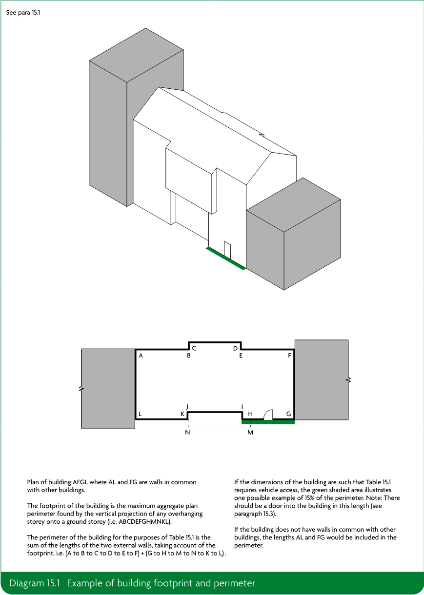
Page 50
#Source page 50
Page 113 Replace Diagram 15.2 with the following.
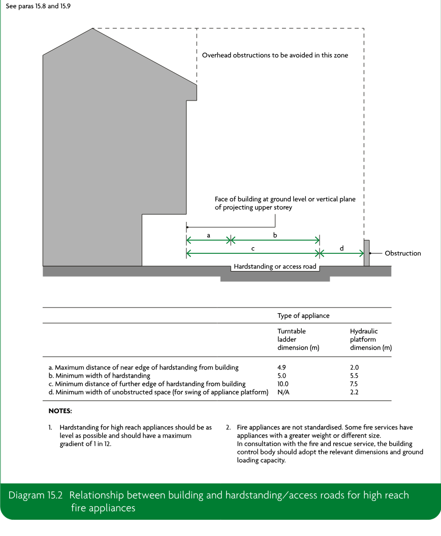
| Turntable ladder dimension (m) | Hydraulic platform dimension (m) | |
|---|---|---|
| a. Maximum distance of near edge of hardstanding from building | 4.9 | 2.0 |
| b. Minimum width of hardstanding | 5.0 | 5.5 |
| c. Minimum distance of further edge of hardstanding from building | 10.0 | 7.5 |
| d. Minimum width of unobstructed space (for swing of appliance platform) | N/A | 2.2 |
Section 18: Venting of heat and smoke from basements
#Source page 51
Page 123 Replace Diagram 18.1 with the following.
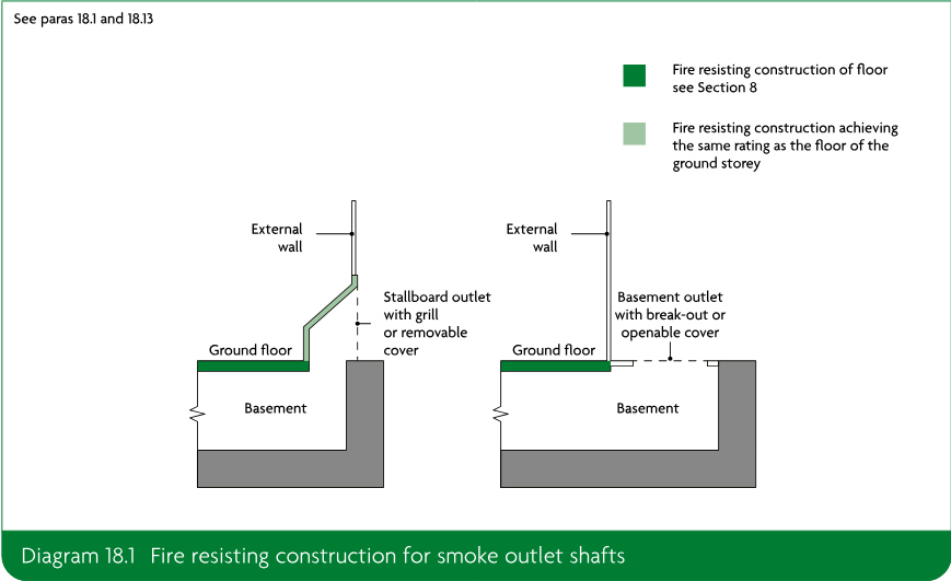
Appendix A: Key terms
Page 130 Insert the following entry between the definitions of Corridor access and Dead end.
Curtain Part of a solar shading device which is set in motion by the operating system and fulfils the purpose of a blind, awning or shutter.
Page 133 Insert the following entry between the definitions of Site and *Specified attachment.
Solar shading device A device attached to an external wall for reducing heat gain or controlling visible light within a building by shading or deflecting sunlight.
Appendix B: Performance of materials, products and structures
#Source page 52
Page 135Replace paragraph B4 with the following.
B4Where it is proposed to assess the classification of a product or system in lieu of carrying out a specific test (as in paragraph B1c), this should be done in accordance with the relevant standard for extended application for the test in question and should include details of the test evidence that has been used to support the assessment.
For performance classifications where there is no specific standard for extended application, assessment reports should be produced in accordance with the principles of BS EN 15725 and should include details of the test evidence that has been used to support the assessment. Further information on best practice is provided in the Passive Fire Protection Forum’s Guide to Undertaking Technical Assessments of the Fire Performance of Construction Products Based on Fire Test Evidence.
Pages 140 to 143Replace paragraph B25 with the following.
B25This document uses the European classification system for fire resistance set out in BS EN 13501-2 to 4; however, there may be some products lawfully on the market using the classification system set out in previous editions. In those situations the alternative classifications given in Table B3 can be used.
In Table B3 Specific provisions of the test for fire resistance of elements of structure, etc., replace rows as follows.
1.Replace row 2 with the following.
| 2. Loadbearing wall (for a wall which is also described in any of the following items, the more onerous guidance should be applied). | R see Table B4 | See Table B4 | Not applicable | Not applicable | Each side separately |
2.Replace row 3b with the following.
| b. in upper storey of two storey dwellinghouse (but not over garage or basement) | R 30 and EI 15 | 30 min | 15 min | 15 min | From underside(5) |
3.Replace row 5b with the following.
| b. any part a minimum of 1000mm from the relevant boundary(6) | RE see Table B4 and I 15 | See Table B4 | See Table B4 | 15 min | From inside the building |
Page 53
#Source page 53
List of approved documents
#Source page 54
The following publications give practical guidance on how to meet the Building Regulations. You can find the date of the edition approved by the Secretary of State at www.gov.uk.
Approved Document A
Structure
Approved Document B
Fire safety Volume 1: Dwellings Volume 2: Buildings other than dwellings
Approved Document C
Site preparation and resistance to contaminants and moisture
Approved Document D
Toxic substances
Approved Document E
Resistance to the passage of sound
Approved Document F
Ventilation Volume 1: Dwellings Volume 2: Buildings other than dwellings
Approved Document G
Sanitation, hot water safety and water efficiency
Approved Document H
Drainage and waste disposal
Approved Document J
Combustion appliances and fuel storage systems
Approved Document K
Protection from falling, collision and impact
Approved Document L
Conservation of fuel and power Volume 1: Dwellings Volume 2: Buildings other than dwellings
Approved Document M
Access to and use of buildings Volume 1: Dwellings Volume 2: Buildings other than dwellings
Approved Document O
Overheating
Approved Document P
Electrical safety – Dwellings
Approved Document Q
Security – Dwellings
Approved Document R
Physical infrastructure for high-speed electronic communications networks
Approved Document S
Infrastructure for the charging of electric vehicles
Approved Document 7
Materials and workmanship
The Building Regulations 2010, Approved Documents are available from:
RIBA Books
Online: www.architecture.com/ribabooks Telephone: +44 (0)20 7496 8383 Email: sales@books.architecture.com
© Crown copyright, 2022
The content of this publication, excluding logos, may be reproduced free of charge in any format or medium for research, private study or for internal circulation within an organisation. This is subject to it being reproduced accurately and not used in a misleading context. The material must be acknowledged as Crown copyright and the title and edition of the publication specified. This document / publication is value added. You may re-use the content (not including logos) free of charge in any format or medium, under the terms of the Open Government Licence.
To view this licence, visit: www.nationalarchives.gov.uk/doc/open-government-licence or write to the Information Policy Team, The National Archives, Kew, London TW9 4DU, or email: psi@nationalarchives.gov.uk.
If you require this publication in an alternative format, please email: alternativeformats@communities.gov.uk.
Copyright in the typographical arrangement, excluding logos, of the cover and internal page layouts of this publication rests with the publisher.