Northern Ireland Technical booklet H
Technical booklet H - Stairs, ramps, guarding and protection from impact - October 2012
Library captured 10 September 2026 · Source updated 22 August 2026
● Finance and ● Personnel
#Source page 1
Department of
● Finance and ● Personnel
G u i d a n c e
Te c h n i c a l B o o k l e t
H
Stairs, ramps, guarding and protection from impact
October 2012
Page 2
#Source page 2
Contents page
Introduction Technical Booklets 3
This Technical Booklet 3
Protected buildings 4
Other legislation 4
Part H Regulations 6
Guidance – Performance and introduction to provisions Stairs, ladders, ramps and their landings 9
Guarding 10
Vehicle loading bays 10
Protection against impact from and trapping by doors 11
Protection from collision with open windows, skylights or ventilators 11
Section 1 General
Definitions 12
Visual contrast 13
Section 2 Access routes to buildings
General 14
Ramps and complementary steps on access routes to buildings other than dwellings 15
Ramped approach 15
Ramped approach with complementary steps 15
Ramps and steps on access routes to dwellings 19
Section 3 Stairs
Common provisions for all stairs 21
Additional provisions for private stairs and common stairs in blocks of dwellings 25
Additional provisions for stairs in buildings other than dwellings 30
Spiral or helical stairs in dwellings 33
Page 3
#Source page 3
| Stairs and fixed ladders providing access for maintenance | 33 | |
|---|---|---|
| Section 4 Ramps in buildings Ramps in dwellings | 34 | |
| Ramps within common areas of a block of dwellings | 35 | |
| Ramps in buildings other than dwellings | 36 | |
| Section 5 Guarding General Guarding of spiral or helical stairs in a dwelling Stair or fixed ladders Vehicle barriers | 39 41 41 41 | |
| Section 6 Vehicle loading bays Loading bays | 42 | |
| Section 7 Protection against impact from and trapping by doors Doors and gates | 43 | |
| Section 8 Protection from collision with open windows, skylights or ventilators General | 44 | |
| Appendix | Publications referred to | 45 |
Technical Booklets
#Source page 4
Introduction
Technical Booklets
This Technical Booklet, which takes effect on 31st October 2012, is one of a series that has been prepared by the Department of Finance and Personnel (the Department) for the purpose of providing practical guidance with respect to the technical requirements of the Building Regulations (Northern Ireland) 2012 (the Building Regulations).
At the back of each Technical Booklet is a list of all the Technical Booklets that have been prepared and published by the Department for this purpose.
The guidance given in a Technical Booklet includes performance standards and design provisions relating to compliance with specific aspects of the Building Regulations for the more common building situations.
If the guidance in a Technical Booklet is followed there will be a presumption of compliance with the requirements of those Building Regulations covered by that guidance. However, this presumption can be overturned, so simply following the guidance does not guarantee compliance. For example, if a particular circumstance is not one of the more common building situations the design provisions given in the Technical Booklet may not be appropriate.
There are likely to be alternative ways of demonstrating compliance with the relevant requirements of the Building Regulations other than by following a design provision given in a Technical Booklet. There is therefore no obligation to adopt any particular provision set out in a Technical Booklet, should you decide to comply in some other way. However, you will have to demonstrate that your alternative solution meets the relevant requirements of the Building Regulations by those other means.
This Technical Booklet
Requirements
The guidance contained in this Technical Booklet relates only to the requirements of regulations 56, 57, 58, 59 and 60. The work will also have to comply with all other relevant requirements of the Building Regulations.
Materials and workmanship
Any building work which is subject to requirements imposed by Part A of the Building Regulations should be carried out in accordance with regulation 23 of those regulations. Guidance on meeting these requirements for materials and workmanship is given in Technical Booklet B which supports Part B.
Protected buildings
#Source page 5
The Building Regulations are made for specific purposes, primarily securing the health, safety, welfare and convenience of people and for the conservation of fuel and power. Standards and technical approvals are relevant guidance to the extent that they relate to these purposes. However, they may also address other aspects of performance such as serviceability, or aspects which although they relate to health and safety are not covered by the Building Regulations.
Named standards
Where this Technical Booklet makes reference to a named standard, the relevant version of the standard is the one listed in the Appendix. However, if this version has been replaced or updated by the issuing standards body, the new version may be used as a source of guidance provided that it continues to address the relevant requirements of the Building Regulations.
Diagrams
The diagrams in this Technical Booklet supplement the text. They do not show all the details of construction and are not intended to illustrate compliance with any other requirement of the Building Regulations. They are not necessarily to scale and should not be used as working details.
Protected buildings
District councils have a duty to take account of the desirability to preserve the character of protected buildings when carrying out their functions under Building Regulations. Therefore, where work is to be carried out to a protected building to comply with Part H or any other Part of the Building Regulations, special consideration may be given to the extent of such work for compliance where it would unacceptably alter the character or appearance of the building. Protected buildings are defined in Article 3A(2) of the Building Regulations (Northern Ireland) Order 1979 (as amended).
Other legislation
The provisions of this Technical Booklet relate to the requirements of Building Regulations and do not include measures which may be necessary to meet the requirements of other legislation. Such other legislation may operate during the design or construction stages or when a building is brought into use and can extend to cover aspects which are outside the scope of the Building Regulations.
The Workplace (Health, Safety and Welfare) Regulations (Northern Ireland) 1993
The Workplace (Health, Safety and Welfare) Regulations (Northern Ireland) 1993 (the Workplace Regulations) contain some requirements which affect building design. The main requirements are now covered by the Building Regulations, but for further information see – The Workplace Regulations and the Workplace Health, Safety and Welfare Approved Code of Practice and Guidance published by TSO.
Page 6
#Source page 6
The Workplace Regulations apply to the common parts of flats and similar buildings if people such as cleaners, wardens and caretakers are employed to work in these common parts. Where the requirements of the Building Regulations that are covered by Part H do not apply to dwellings, the provisions may still be required in the situations described above in order to satisfy the Workplace Regulations.
PART H
#Source page 7
Part H Regulations
Part H (comprising regulations 54 to 60) of the Building Regulations, which sets out the requirements for stairs, ramps, guarding and protection from impact, has been replicated for the convenience of the user of this Technical Booklet and is taken directly from the Building Regulations (Northern Ireland) 2012.
Any person who intends to demonstrate compliance with the Building Regulations by following the guidance given in this Technical Booklet is advised to ensure that the regulations below, are current on the date when plans are deposited or notices given to the district council.
As Part A (comprising regulations 1 to 21) of the Building Regulations sets out the interpretation along with the procedural requirements relating to the application of the regulations, the Department advises that all Parts of the Building Regulations are read in conjunction with Part A of those regulations.
The Building Regulations (Northern Ireland) 2012 and any subsequent amendment/s may be viewed by following the links from the Department’s website at “www.buildingregulationsni.gov.uk”.
PART H
Stairs, ramps, guarding and protection from impact
Application and interpretation
54.—(1) Subject to paragraphs (2) to (6), this Part shall apply to any building or part of a building.
(2)The requirements of regulation 56 shall only apply where a stair, ladder or a ramp and landings—
(a)forms part of the building;
(b)that does not form part of the building, is provided to comply with the requirements of Part E or Part R; or
(c)provides access to an entrance or exit of the building and the general ground level immediately outside that entrance or exit.
(3)The requirements of regulation 57(1) shall not apply—
(a)to the extent that compliance therewith would unreasonably obstruct normal movement to, into, out of or within any building;
(b)in relation to the two steps at the bottom of a stair where the landing from which the stair rises does not require guarding in accordance with that paragraph;
(c)in relation to a flight within a stair with a total rise of less than 600 mm;
(d)in relation to a sunken area less than 600 mm in depth; and
(e)in relation to a roof or other place to which access is solely for maintenance purposes provided that either—
(i)access is infrequent; or
(ii)any fall would be— (aa) less than 2000 mm; or (bb) to an area which does not present a hazard.
Provision of stairs in dwellings
#Source page 8
(4)The requirements of regulation 57(2) shall not apply in relation to a car showroom, a garage within the boundary of a dwelling, or a single storey building comprising two or more garages each of which has an area not exceeding 40 m2.
(5)The requirements of regulation 59 shall not apply to—
(a)a dwelling; and
(b)a door or gate which is part of a lift.
(6)Insofar as they relate to a dwelling, the requirements of regulation 60 shall only apply to a window, skylight or ventilator which opens over a public route of travel.
(7)For the purposes of this Part access to any place is infrequent if it takes place on average on less than one occasion a month during the course of a year.
(8)In this Part— “Balcony” includes a gallery; “Barrier” includes a wall or screen; “Flight” means that part of a stair or ladder between landings that has a step or a continuous
series of steps; “Ladder” means a fixed ladder having a flight with a pitch greater than 55º; “Landing” means a platform situated—
(a)at the top or bottom of a stair, ladder or ramp; and
(b)between consecutive flights of stairs; “Ramp” means an inclined surface which provides a route of travel; and “Stair” means a flight or flights (other than a ladder) and landings that make it possible to
pass on foot to another level or levels.
Provision of stairs in dwellings
55.Within every dwelling of more than one storey there shall be provided between such storeys access by means of a stair complying with the relevant provisions in this Part:
Provided that nothing in this regulation shall require the provision of a stair to any storey within a dwelling if that storey is used only as general storage accommodation.
Stairs, ladders, ramps and landings
56.In a building or within the boundary of a building a stair, ladder and a ramp and its landings, shall offer reasonable safety to people using them.
Guarding
57.—(1) A stair, ladder, ramp, floor, balcony, landing, platform and any roof or other place to which people normally have access (including access for the purpose of maintenance) and a sunken area next to a building, shall, where it is necessary to protect people approaching, accessing, moving between levels within or exiting that building from the risk of falling, be adequately guarded with a barrier which does not present a hazard.
(2) Any part of a building which is a vehicle ramp, floor or roof to which vehicles have access shall, where it is necessary to protect people, be adequately guarded with a barrier which does not present a hazard.
Vehicle loading bays
58.A vehicle loading bay shall be designed and constructed to minimise the risk of people in it from being struck by a vehicle.
Protection against impact from and trapping by doors
#Source page 9
59.—(1) In any building a door or gate which—
(a)is across a main route of travel; or
(b)can be pushed open from either side,
shall have a means to ensure that people approaching it have a clear view of the space on the opposite side.
(2)In any building a door or gate which slides or opens upwards shall have a means to prevent it from sliding into or falling on any person.
(3)In any building a powered door or gate shall have a means to prevent it trapping any person and a means to open it in the event of a power failure.
Protection from collision with open windows, skylights or ventilators
60.Reasonable provision shall be made to minimise the risk of people colliding with an open window, skylight or ventilator when moving in or about a building.
Stairs, ladders, ramps and their landings
#Source page 10
Guidance – Performance and introduction to provisions
Stairs, ladders, ramps and their landings
General
0.1Provisions for accessibility to and within a building are given in Part R. Provisions for fire safety are given in Part E. A stair or a ramp and its landings provided –
(a)so that people may move to, out of or within a building; or
(b)to comply with Part E or Part R,
must comply with the relevant requirements of Part H.
Performance
0.2It is the view of the Department that the requirements of regulation 56 in Part H will be met when a stair, ladder, ramp and its landings afford reasonable safety to people who use them. As there is a correlation between ease of use and safety, a stair or ramp that offers passage without undue effort or exertion further reduces the potential for an incident that may result in injury.
An appropriate level of safety can be achieved by different standards of provision, depending on the circumstances; for example, in a building to which the public are admitted, the standard of provision may be higher than in a dwelling, to reflect the lesser familiarity and greater number of users.
Where access is required only for the purpose of maintenance, greater care can be expected from those gaining access, and it would be reasonable that less demanding provisions could satisfy the requirement.
Introduction to provisions in Section 2
0.3This Section of the guidance deals specifically with various aspects of the geometry and safety features for –
(a)ramps and complementary steps on access routes to buildings other than dwellings; and
(b)ramps and steps on access routes to dwellings.
Introduction to provisions in Sections 3 and 4
0.4The guidance in Section 3 is concerned with various aspects of the geometry and safety of stairs and certain ladders. This includes common provisions for all stairs and additional provisions for –
(a)private stairs;
(b)common stairs in blocks of flats; and
(c)stairs in buildings other than dwellings.
Guarding
#Source page 11
Provisions are also given for spiral and helical stairs in a dwelling and stairs and ladders used solely for the purpose of providing access for maintenance in buildings other than dwellings.
The guidance in Section 4 deals with various aspects of the geometry and safety features of ramps and their landings.
Guarding
Performance
0.5It is the view of the Department that the requirements of regulation 57 in Part H will be met if, in order to reduce the risk to the safety of people in or about buildings –
(a)pedestrian guarding is provided in buildings which is capable of preventing people from being injured by falling from a height;
(b)vehicle barriers are provided which are capable of resisting or deflecting the impact of vehicles.
An appropriate level of safety can be achieved by different standards of provision for guarding, depending on the circumstances; for example, in a building to which the public are admitted, the standard of provision may be higher than in a dwelling, to reflect the lesser familiarity and greater number of users.
Where access is required only for the purpose of maintenance, greater care can be expected from those gaining access, and it would be reasonable that less demanding provisions could satisfy the requirement.
Introduction to provisions in Section 5
0.6The guidance in Section 5 is concerned with reducing the risk of people falling from a height. This includes provisions for guarding flights, ramps, landings and raised floors. This Section also contains guidance in relation to protecting people whenever vehicles have access to a building.
Vehicle loading bays
Performance
0.7It is the view of the Department that the requirements of regulation 58 in Part H will be met if, in order to reduce the risk to the safety of people in or about buildings, loading bays are provided with an adequate number of exits or refuges which enable people to avoid being struck or crushed by vehicles.
Introduction to provisions in Section 6
0.8The guidance in Section 6 deals specifically with reducing the risk to the safety of people in loading bays. This includes the provision of suitable exits or refuges which enable people to avoid being struck or crushed by vehicles.
Protection against impact from and trapping by doors
#Source page 12
Performance
0.9It is the view of the Department that the requirements of regulation 59 in Part H will be met if, measures are taken to prevent doors and gates presenting a safety hazard whenever they are opening or closing. Such measures include –
(a)ensuring a clear view of the space on the opposite side of the door to that of the users approach in order to reduce the risk of the door striking someone;
(b)where a door slides or opens upwards, adequate means are provided to prevent such a door sliding into or falling onto anyone; and
(c)where there is a powered door or gate, there should be suitable means to prevent someone being trapped by such a door or gate and a means to open it should the power fail.
Introduction to provisions in Section 7
0.10The guidance in Section 7 deals with reducing the risk of people being struck by, or trapped by, doors or gates when they are opening or closing.
Protection from collision with open windows, skylights or ventilators
Performance
0.11It is the view of the Department that the requirements of regulation 60 in Part H will be met if windows, skylights or ventilators can be left open without the danger of people colliding with them. This could be achieved by –
(a)installing windows, skylights or ventilators, so that projecting parts are kept away from people moving in or about a building; or
(b)installing features which guide people moving in or about a building away from any open window, skylight or ventilator.
An appropriate level of safety can be achieved by different standards of provision, depending on the circumstances; for example, in a building to which the public are admitted, the standard of provision may be higher than in a dwelling, to reflect the lesser familiarity and greater number of users.
Where access is required only for the purpose of maintenance, greater care can be expected from those gaining access, and it would be reasonable that less demanding provisions could satisfy the requirement.
Introduction to provisions in Section 8
0.12The guidance in Section 8 is specifically concerned with reducing the risk of people colliding with open windows, skylights or ventilators.
Definitions
#Source page 13
Section 1 General
Definitions
1.1In this Technical Booklet the following definitions apply –
Dwelling – has the meaning assigned to it by regulation 2 in Part A of the Building Regulations.
Entrance storey – means the storey which contains the principal entrance for the dwelling.
Flight – has the meaning assigned to it by regulation 54 in Part H of the Building Regulations.
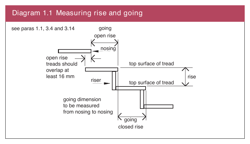
Going (in relation to a step) – the depth of the tread less any overlap with the next tread (see Diagram 1.1).
Habitable room – has the meaning assigned to it by regulation 2 in Part A of the Building Regulations.
Ladder – has the meaning assigned to it by regulation 54 in Part H of the Building Regulations.
Landing – has the meaning assigned to it by regulation 54 in Part H of the Building Regulations.
Principal storey – the storey nearest to the entrance storey which contains a habitable room, or if there are two such storeys equally near, either such storey.
Private stair – a stair in or intended to be used by only one dwelling.
Ramp – has the meaning assigned to it by regulation 54 in Part H of the Building Regulations.
Retail building – shop, department store, supermarket, public house, restaurant with or without assembly area, cafe, hairdresser, wholesale self selection trading, public area of a bank, building society, betting shop.
Rise (in relation to a step) – the height, including the thickness of the tread (see Diagram 1.1).
Small room – any room in a dwelling having a floor area not exceeding 4 m2.
Stair – has the meaning assigned to it by regulation 54 in Part H of the Building Regulations.
Step – in a dwelling, does not include any threshold which has a height not exceeding 40 mm in the case of an internal doorway or 75 mm in the case of an external doorway.
Visual contrast
#Source page 14
Surface width – the width of a stair or ramp, measured at the tread of a step or the surface of a ramp, between any enclosing walls, strings, upstands, kerbs or guarding.
Tapered tread – a tread which has a greater width at one side than at the other and a going which changes at a constant rate throughout its length.
Diagram 1.1 Measuring rise and going
Visual contrast
1.2Visual contrast is the perception of a difference visually between one element of a building and another by reference to their light reflectance values.
Light reflectance value (LRV) is the total quantity of visible light reflected by a surface at all wavelengths and directions when illuminated by a light source.
For people with adequate vision, differences in the nature or the intensity of colour provide adequate visual contrast. Unfortunately, this is not the case for all people who are visually impaired. The main feature of a surface, which appears to be strongly correlated with the ability of visually impaired people to identify differences in colour, is the LRV. Differences in LRV can be used to assess the degree of visual contrast between the surfaces of elements such as handrails, step nosings, etc.
The LRV scale runs from 0, which is a perfectly absorbing surface that could be assumed to be totally black, up to 100, which is a perfectly reflective surface that could be considered to be the perfect white. Because of practical influences in any application, black is always greater than 0 and white never equals 100.
A difference in LRV of 30 points or more allows a degree of variability that is required to provide reasonable visual contrast.
General
#Source page 15
Section 2 Access routes to buildings
General
2.1Section 2 gives guidance on appropriate levels of safety and convenience for all users where a ramp or a ramp and complementary steps are to be provided as an access route or part of an access route to a building.
2.2This Section is presented as follows –
Ramps and complementary steps on access routes to buildings other than dwellings; and Ramps and steps on access routes to dwellings.
Ramps and complementary steps on access routes to buildings other than dwellings
#Source page 16
Ramped approach
Ramps on access routes
2.3
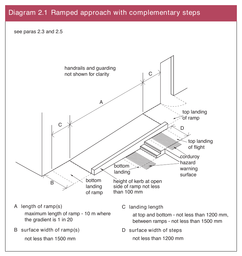
Ramps on access routes should comply with the provisions given in paragraphs 4.14 to 4.25. See Diagram 2.1. However, where an external ramp has a crossfall, that crossfall should have a maximum gradient of 1:40.
Ramped approach with complementary steps
2.4Visually impaired people risk tripping or losing their balance if there is no warning that there is a change in level. Tripping is most hazardous at the head of a flight of steps when a person is descending. The warning should be placed sufficiently in advance of the hazard to allow time to stop and not be so narrow that it might be missed in a single stride.
2.5People who wear callipers or who have stiffness in hip or knee joints are particularly at risk of tripping or catching their feet beneath nosings. People with a weakness on one side or with a sight impairment need the dimensions of the tread to be sufficient for them to be able to place their feet square onto it. If the going is towards the upper end of the dimensional range, the flight may rise to a greater height without the need for an intermediate landing, as the tread is sufficiently deep to allow a person to stand and rest at any point within the flight.
An example of a ramped approach with complementary steps is given in Diagram 2.1.
Where complementary steps and a ramp share a surface containing their respective notional landings, it is preferred that the tactile warning surface be located clear of the ramp landing.
Page 17
#Source page 17
Diagram 2.1 Ramped approach with complementary steps
Complementary steps
2.6Steps should have a uniform –
(a)rise of not less than 150 mm and not more than 170 mm; and
(b)going of not less than 280 mm and not more than 425 mm.
2.7A flight of steps should have not less than 2 rises or more than –
(a)12 rises where the going of each step is less than 350 mm; or
(b)18 rises where the going of each step is 350 mm or more.
2.8A flight should have a surface width of not less than that given in paragraph 3.32.
2.9Steps should also comply with the guidance given in paragraphs 3.33 to 3.35.
2.10To assist a person who is weaker on one side and a visually impaired person, steps should have a suitable continuous handrail on each side complying with the provisions of paragraphs 3.37 to 3.43.
Page 18
#Source page 18
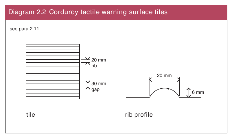
2.11To give advance warning of the change in level, a tactile corduroy surface should be provided on the top and bottom landings of complementary steps. See Diagram 2.2. The size of this surface should be –
(a)800 mm deep when the approach to the steps is head on; or
(b)400 mm deep when the approach to the steps is not head on.
In either case, the surface should extend not less than 400 mm beyond each side of the steps and be located not less than 400 mm from the nearest nosing. See Diagram 2.3.
Diagram 2.2 Corduroy tactile warning surface tiles
2.12Where there is access onto any intermediate landing from other than the complementary steps, a tactile corduroy surface 400 mm deep should be provided in accordance with Diagram 2.3 (b) or (c).
Diagram 2.3 Complementary steps tactile warnings
#Source page 19
see para 2.11 and 2.12 not less than 400 mm corduroy hazard warning surface stair width corduroy hazard warning surface not less than to extend not less than 400 mm at 400 mm each side of the flight (unless the landing is bounded at a distance of less than 400 mm by a return wall) and stop 400 mm from the
| nearest nosing | corduroy hazard warning | ||
|---|---|---|---|
| corduroy hazard warning surface | 400 mm | surface to the top and bottom landings should be 800 mm deep where the approach to the steps is head-on and 400 mm | |
| deep where the approach is | |||
| not head-on | |||
| (a) tactile warning | bottom landing | 400 mm | not less than 400 mm |
stair width not less than 400 mm not more than 1200 mm and not less than top landing 800 mm corduroy hazard 400 mm warning surface
400mm visual contrast to tread and riser
400mm
400mm bottom landing 400 mm
(b) external steps showing side access onto intermediate landing and having not less than not less than
800 mm from the access to the top and bottom
400mm
of flights
stair width not less than 400 mm corduroy hazard less than warning surface top landing less than 800 mm corduroy hazard 800 mm 400 mm warning surface visual contrast continuous handrail to tread and riser opposite access bottom landing 400 mm
(c) external steps showing side access onto intermediate landing and having less than 800 mm from the access to the top and bottom of flights
Ramps and steps on access routes to dwellings
#Source page 20
Ramped approach
2.13A ramped approach should have –
(a)a surface which is firm and even;
(b)an unobstructed width not less than 900 mm;
(c)a ramp or ramps not exceeding –
(i)10 m in length where the slope of the ramp does not exceed 1 in 15; or
(ii)5 m in length where the slope of the ramp does not exceed 1 in 12;
(d)landings with an unobstructed length of not less than 1200 mm;
(e)headroom complying with the provisions of paragraph 4.7; and
(f)handrails complying with the provisions of paragraph 4.8.
Stepped approach
2.14A stepped approach should have –
(a)a flight or flights with an unobstructed width of not less than 900 mm;
(b)a rise of not more than 1800 mm in each flight of steps;
(c)steps with a uniform rise of not less than 75 mm and not more than 150 mm;
(d)steps with a uniform going of not less than 280 mm (which in the case of tapered treads should be measured at a point 270 mm from the narrow end);
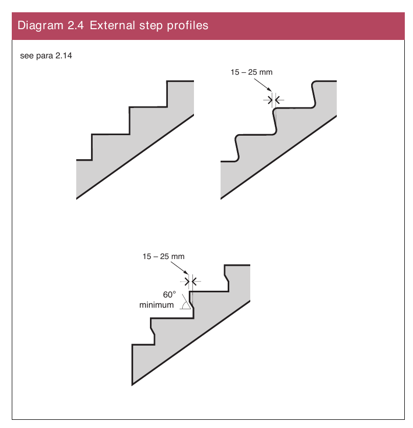
(e)steps that are not open and have a suitable profile such that the risk of tripping is reduced. See Diagram 2.4;
(f)a maximum of 16 steps in a flight;
(g)landings with an unobstructed length of not less than 900 mm; and
(h)a suitable continuous handrail (see paragraph 2.15) on one side of the flight and at an intermediate landing where the flight comprises three or more steps.
2.15A stepped approach should have a suitable handrail which –
(a)is at a height measured vertically of –
(i)900 mm above the pitch line of a flight of steps; and
(ii)1000 mm above the surface of a landing; and
(b)extends not less than 300 mm horizontally beyond the top and bottom nosings of a flight of steps.
Page 21
#Source page 21
Diagram 2.4 External step profiles
Common provisions for all stairs
#Source page 22
Section 3 Stairs
General
3.1This Section gives guidance on appropriate levels of safety and convenience for all users where a stair is to be provided so that people can move between levels or storeys in a building.
Provisions are also given for a stair or a fixed ladder providing access solely for the purpose of maintenance.
Common provisions for all stairs
3.2A private stair or a common stair in a block of dwellings, should comply with the provisions of paragraphs 3.4 to 3.28.
3.3A stair, other than a private stair or a common stair in a block of dwellings, should comply with the provisions of paragraphs 3.4 to 3.11 and 3.29 to 3.43.
Pitch
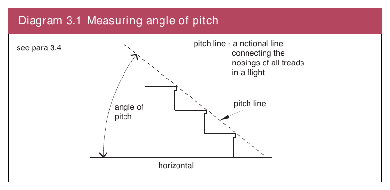
3.4The pitch of a flight is controlled by limiting the rise and the going.
Diagram 3.1 shows how to measure the pitch and what is meant by the pitch line. Diagram 1.1 shows how to measure the rise and going (for steps with tapered treads see also paragraph 3.20).
Diagram 3.1 Measuring angle of pitch
Page 23
#Source page 23
3.5Subject to paragraph 3.12 the relationship between the dimensions of the rise and going is that twice the rise (R) plus the going (G) i.e. (2R + G) should be between 550 mm and 700 mm. The rise and the going are given in Table 3.1.
| Table 3.1 Rise and going | |||
|---|---|---|---|
| Category | Rise | Going | |
| minimum (mm) | maximum (mm) | minimum (mm) | |
| Private stair | 75 | 220* | 220* |
| A common stair in a block of dwellings | 75 | 170 | 250 |
| A stair in any building (other than a private stair or a common stair in a block of dwellings) | 150 | 170 | 250 |
| Note: A stair within more than one category should be constructed to the more onerous standard. * see also paragraph 3.12. |
3.6In a flight, the steps should all have the same rise and they should all have the same going.
3.7Where the landing of a stair is formed by the ground and slopes across the width of the flight, then the rise of the step should be measured at the mid point of the width of the flight. See paragraph 3.11.
3.8Steps should have level treads which extend for the full width of the flight.
Headroom
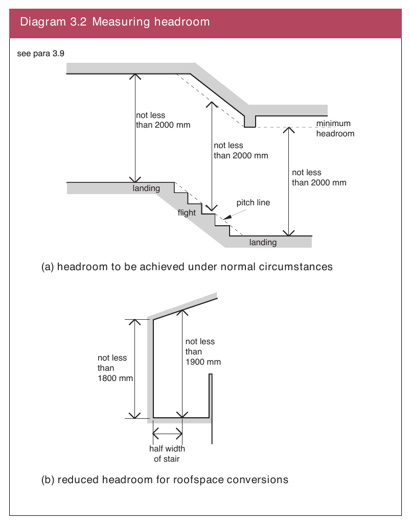
3.9A stair should have a clear headroom of not less than 2000 mm over its full length and width.
Headroom is measured vertically from the pitch line of the flight and the level of the landing. See Diagram 3.2(a).
For roofspace conversions in a dwelling, where it can be demonstrated that there is not enough space to achieve a clear headroom of at least 2000 mm, it would be reasonable for a stair to have headroom as shown in Diagram 3.2(b).
Page 24
#Source page 24
Diagram 3.2 Measuring headroom
Page 25
#Source page 25
Change of direction
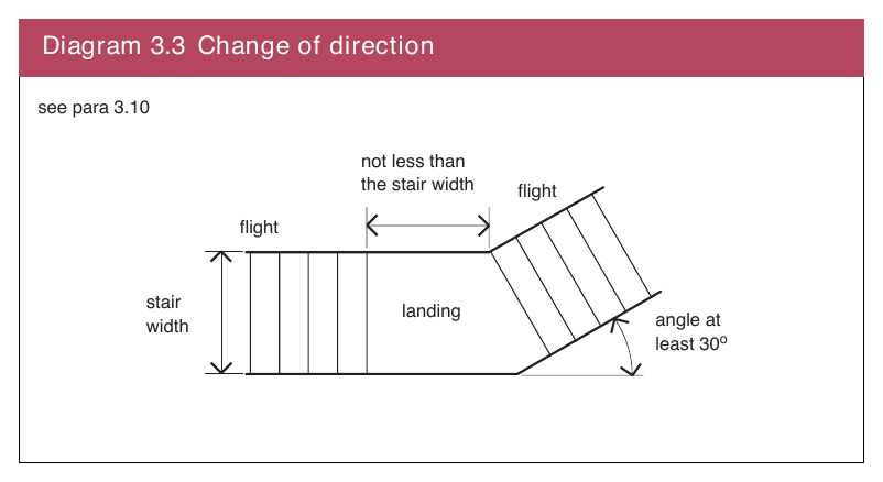
3.10A stair of more than 36 rises in consecutive flights should have at least one change in direction between flights of at least 30° (see Diagram 3.3).
Diagram 3.3 Change of direction
Landings
3.11Landings should be level unless they are formed by the ground at the top or bottom of a flight where they may have a gradient not greater than –
(a) 1 in 20 in the case of a private stair; or
(b) 1 in 60 for all other stairs. Landings formed by the ground should be paved or otherwise made firm.
Additional provisions for private stairs and common stairs in blocks of dwellings
#Source page 26
Pitch
3.12The pitch of a private stair should not exceed 42°, therefore it is not possible to combine a maximum rise with a minimum going.
The rise and the going are given in Table 3.1.
Width of flights
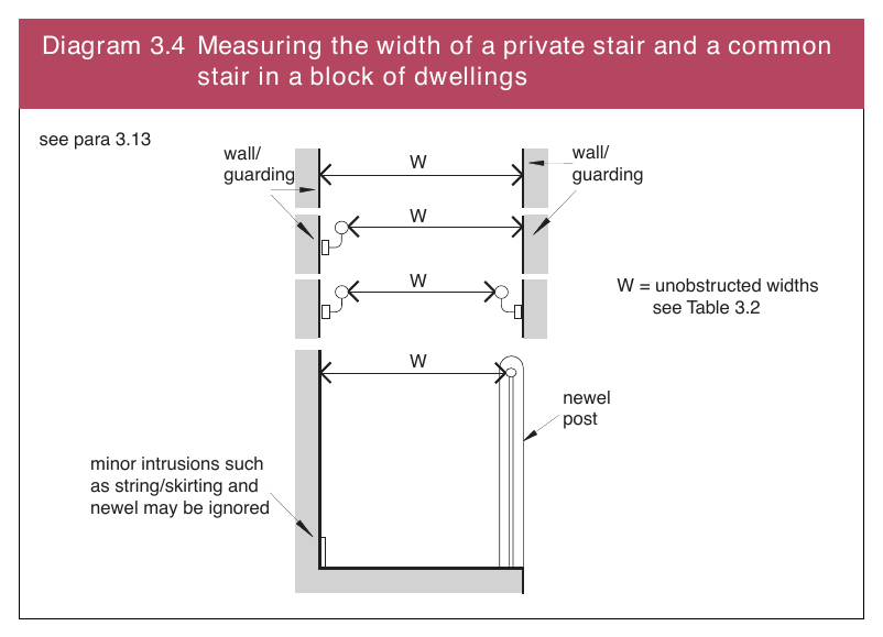
3.13The minimum unobstructed widths for a flight, in a private stair and a common stair in a block of dwellings, are given in Table 3.2 and should be measured in accordance with Diagram 3.4.
| Table 3.2 Widths of flights in a private stair and a common stair in a block of dwellings | |
|---|---|
| Category | Minimum unobstructed width (mm) |
| Private stair (a) providing access to one room only (not being a kitchen or living room) or to a bathroom and a water closet (b) other than (a) above* | 600 800 |
| A common stair in a block of dwellings | 1000 |
| Note * where the private stair (a) is part of the circulation route within the entrance storey; or (b) gives access to the circulation route within the principal storey, the unobstructed width should be not less than 900 mm. |
Diagram 3.4 Measuring the width of a priv stair in a block of dwellingsate stair and a common
Page 27
#Source page 27
Construction of steps
3.14A private stair may have steps with open rises, but the treads should then overlap each other by at least 16 mm. See Diagram 1.1.
A private stair which has open rises, should be constructed so that a 100 mm diameter sphere cannot pass through the open rises.
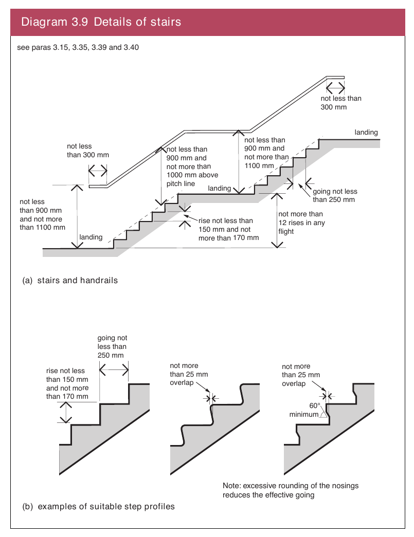
3.15A common stair in a block of dwellings should have steps with rises that are not open, step nosings which are distinguishable, through permanent contrasting brightness and have a suitable profile such that the risk of tripping is reduced. See Diagram 3.9 (b).
3.16The number of rises in a flight should be a maximum of 16 and a minimum of 2. However, notwithstanding the provisions of paragraph 3.19, a single step may be provided –
(a)at the bottom of a stair in a dwelling;
(b)at an entrance to a dwelling;
(c)between any enclosed porch, outhouse or conservatory and the remainder of a dwelling;
(d)where it provides access to a small room; or
(e)between a garage and a dwelling.
Landings
3.17A landing should be provided at the top and bottom of every flight.
The width of a landing should be not less than the width of the stair.
The going of a landing should be not less than –
(a)in a private stair, the width of the flight; and
(b)in a common stair in a block of dwellings, 1200 mm clear of any door swing onto them.
Part of a floor may be considered as a landing.
3.18To afford safe passage a landing should be clear of any obstruction. However, in a private stair –
(a)a door may swing across a landing at the bottom of a flight but only where it will leave a clear space of at least 400 mm across the full width of the flight. See Diagram 3.5; and
(b)a door to a cupboard or duct may swing across a landing at –
(i)the bottom of a flight; and
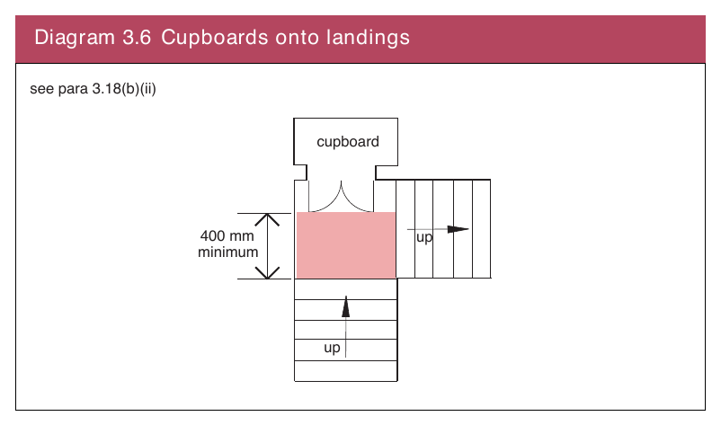
(ii)the top of a flight where it will leave a clear space of 400 mm across the full width of the flight. See Diagram 3.6.
Page 28
#Source page 28
Diagram 3.5 Landings next to doors
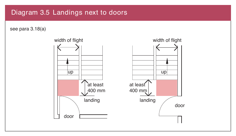
Diagram 3.6 Cupboards ontolandings
3.19A landing need not be provided between an external flight and a doorway if the rise of the flight is not more than 600 mm and the door slides or opens away from the steps.
Where there is a single step between a garage and a dwelling, a door may open out over the step when the door, in the closed position, has some part of its thickness in line with the riser of the step.
Steps with tapered treads
3.20Where steps have tapered treads, the going should be measured as follows –
(a)if the width of the flight is less than 1000 mm, measure in the middle or;
(b)if the width of the flight is 1000 mm or more, measure 270 mm from each side.
(See Diagram 3.7.)
Page 29
#Source page 29
Diagram 3.7 Measuring tapered treads
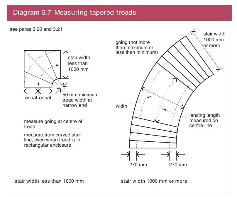
3.21The narrow ends of consecutive treads should be on the same side of the stair and have a going of not less than 50 mm. See Diagram 3.7.
3.22The rise and the going measured at the positions, in paragraph 3.20 (a) or
(b) whichever is appropriate should be within the limits given in paragraphs 3.5 and 3.12 and Table 3.1.
3.23Where a stair consists of straight and tapered treads, the going of the tapered treads should be not less than the going of the treads on the straight flight.
Handrails
3.24Flights in a private stair with a total rise of more than 600 mm and a common stair in a block of dwellings, should have a continuous handrail that gives firm support and a firm grip and be located –
(a)on at least one side where the stair is less than 1000 mm wide; or
(b)on both sides where the stair is 1000 mm wide or more.
Where only one handrail is required on a flight with tapered treads, it should be located on the outer side of the flight.
3.25Notwithstanding the provisions of paragraph 3.24, where a private stair –
(a)is part of the circulation route within the entrance storey of a dwelling; or
(b)gives access to the circulation route within the principal storey of a dwelling,
the stair should have a continuous handrail on each side.
Page 30
#Source page 30
3.26Handrails are not required beside the two steps at the bottom of a private stair.
3.27Handrails should be at a height between 900 mm and 1000 mm measured vertically above the pitch line.
Handrails may form the top of guarding.
3.28To give warning of a change in level i.e. the start or finish of a flight, the handrail to a common stair in a block of dwellings, should extend horizontally for a distance of not less than 300 mm, along the top and bottom landings.
Additional provisions for stairs in buildings other than dwellings
#Source page 31
3.29Paragraphs 3.4 to 3.11 and 3.30 to 3.43 apply to a stair other than a private stair or a common stair in a block of dwellings.
Pitch
3.30The rise and the going are given in Table 3.1.
3.31There should be not less than 2 rises and not more than 12 rises in each flight.
There may be exceptional circumstances where a different rise or greater number of rises in a flight is more appropriate e.g. where there are dimensional constraints imposed by an existing building.
Width of flights
3.32A flight should have a surface width of not less than 1200 mm.
Where a handrail protrudes into the surface width of a flight by more than 100 mm, the surface width should be increased accordingly. In any case, the maximum protrusion of a handrail into the surface width of a flight should be 110 mm.
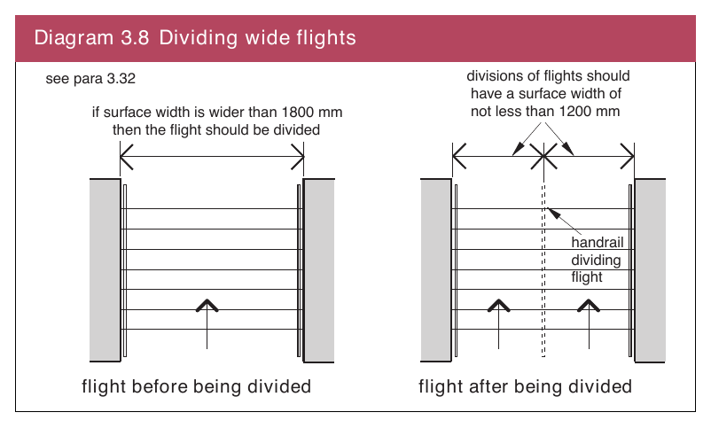
A flight of steps which has a surface width wider than 1800 mm, should be divided into flights which are not wider than 1800 mm. The minimum surface width of 1200 mm then applies to each flight. See Diagram 3.8.
Diagram 3.8 Dividing wide flights
Construction of steps
3.33So a visually impaired person can appreciate the extent of the stair and identify individual treads, steps should have step nosings which are distinguishable through suitable permanent visual contrast. The width of this permanent visual contrast should be not less than 50 mm and not more than 60 mm to all treads and risers.
3.34Anything fixed or fitted to a tread or riser should not create a trip hazard.
Page 32
#Source page 32
3.35Steps should have rises that are not open and have a suitable profile such that the risk of tripping or people catching their feet beneath the nosing, is reduced (see Diagram 3.9).
Landings
3.36A landing should be provided at the top and bottom of every flight. The width of the landing should be not less than the width of the stair. To afford safe passage, the unobstructed length of each landing should be not less than 1200 mm clear of any door swing onto it. Part of a floor may be considered as a landing.
Diagram 3.9 Details of stairs
Page 33
#Source page 33
Handrails
3.37A suitably designed handrail can help prevent people losing their balance when on the stair and can also assist users to ascend by pulling themselves up the stairs.
Handrails may form the top of guarding where the required height of the handrail aligns with the required height of the guarding.
3.38A stair should have a suitable continuous handrail on each side.
3.39A handrail should be at a height measured vertically of –
(a)not less than 900 mm and not more than 1000 mm, above the pitch of a flight; and
(b)not less than 900 mm and not more than 1100 mm, above the surface of a landing.
See Diagram 3.9.
Where it is decided to provide a second lower handrail, for use by children and people who are short in stature, that handrail should be 600 mm above the pitch of the flight. However, this second lower handrail must not impinge on the protection against falling provided by any necessary guarding.
3.40To give warning of a change in level i.e. the start or finish of a flight, each end of a handrail should extend horizontally for a distance of not less than 300 mm, along the top and bottom landings of a stair, be closed and terminate in a suitable way so that –
(a)it does not project into a route of travel; and
(b)it reduces the risk of clothing being caught.
See Diagram 3.9.
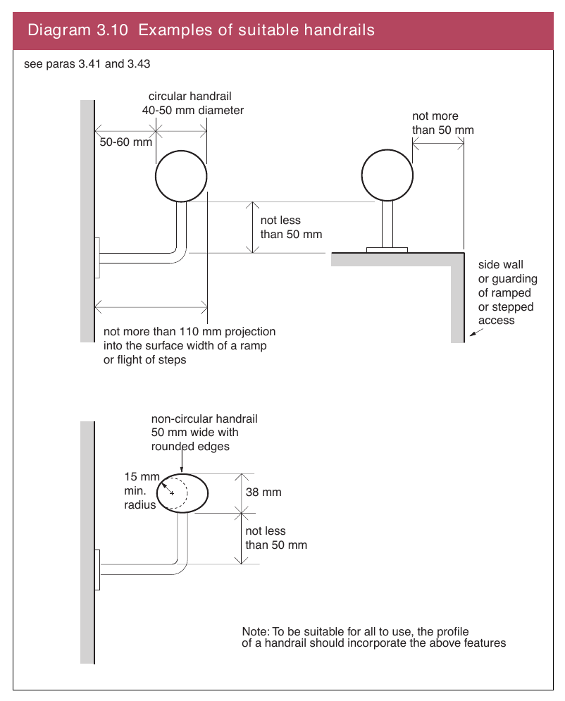
3.41Handrails should be rigidly supported in a way that avoids impeding the users grip.
A handrail should be –
(a)not less than 50 mm and not more than 60 mm clear of any adjacent side or enclosing surface wall, or guarding, etc.;
(b)not less than 50 mm clear from the underside of the handrail to any cranked support; and
(c)not more than 50 mm beyond the outer edge of a flight of steps, to the inner side of the handrail.
See Diagram 3.10.
3.42The surface of a handrail should be distinguishable through suitable visual contrast from the background against which it is seen.
3.43Handrails should allow users to make a power grip around the whole handrail. A noncircular handrail with a broad horizontal face is as easy to grip as a circular handrail and gives better hand and forearm support.
A handrail should have a suitable profile that is gripped easily. Suitable handrail profiles include circular and oval. (see Diagram 3.10).
Spiral or helical stairs in dwellings
#Source page 34
Diagram 3.10 Examples of suitable handrails
Spiral or helical stairs in dwellings
3.44In a dwelling, a spiral or helical stair should be designed and constructed in accordance with BS 5395: 2.
Stairs and fixed ladders providing access for maintenance
3.45A stair or a fixed ladder in a building other than a dwelling, providing access solely for the purpose of maintenance should be designed and constructed in accordance with either BS 5395: 3 or BS 4211.
Ramps in dwellings
#Source page 35
Section 4 Ramps in buildings
General
4.1This Section gives guidance on appropriate levels of safety and convenience for all users where a ramp is to be provided as a means of circulation within a building.
Ramps in dwellings
Gradient
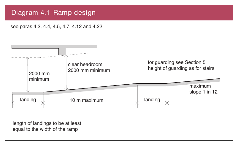
4.2A ramp should have a gradient not steeper than 1 in 12 and should be uniform throughout its length. See Diagram 4.1.
Width of ramps
4.3The minimum width for a ramp should be the same as that for a flight in a private stair, see paragraph 3.13 and Table 3.2.
4.4The length of a ramp measured on plan, should not exceed 10 m. See Diagram 4.1.
Landings
4.5Landings should be level and be provided at the top and bottom of a ramp. See Diagram 4.1.
The width and length of a landing should be not less than the width of the ramp. Part of a floor may be considered as a landing.
4.6Ramps should be clear of obstructions and landings should be clear of obstructions other than those described in paragraph 3.18.
Headroom
4.7Ramps and associated landings should have a clear headroom of not less than 2000 mm over the length and width of the ramp.
Headroom is measured vertically from the slope of the ramp and the level of the landing. See Diagram 4.1.
Ramps within common areas of a block of dwellings
#Source page 36
Diagram 4.1 Ramp design
Handrails
4.8A ramp or a series of ramps with a total rise of more than 600 mm should have a continuous handrail that gives firm support and a firm grip –
(a)on at least one side where the ramp is 1000 mm wide or less; or
(b)on both sides where the ramp is more than 1000 mm wide.
Handrails should be at a height between 900 mm and 1000 mm measured vertically above the surface of the ramp.
Handrails may form the top of guarding.
Ramps within common areas of a block of dwellings
Length and gradient
4.9A ramp should be not more than –
(a)10 m in length where the gradient of the ramp does not exceed 1 in 15; or
(b)5 m in length where the gradient of the ramp does not exceed 1 in 12.
Width of ramps
4.10A ramp should have a surface width of not less than 1200 mm. Where a handrail is provided, the width at handrail level may be reduced to not less than 1000 mm.
Ramps in buildings other than dwellings
#Source page 37
Landings
4.11Landings should be level with an unobstructed length of not less than 1200 mm.
Headroom
4.12Ramps and associated landings should have a clear headroom of not less than 2000 mm over the length and width of the ramp.
Headroom is measured vertically from the slope of the ramp and the level of the landing. See Diagram 4.1.
Handrails
4.13A ramp should have a suitable continuous handrail on each side if the horizontal length of the ramp is more than 2000 mm.
Handrails should be at a height between 900 mm and 1000 mm measured vertically above the surface of the ramp, give firm support and allow a firm grip.
Ramps in buildings other than dwellings
4.14Gradients of ramps should be as shallow as practicable as steep gradients may not be safe or convenient for all people.
The following provisions apply to a ramp which is not in a dwelling or in a block of dwellings.
Length and gradient
4.15The maximum length of a ramp is dependent upon its gradient. Table 4.1 gives the maximum length of a ramp for a given gradient.
There may be exceptional circumstances where a different gradient of ramp to that shown in Table 4.1 over a short distance is more appropriate e.g. where there are physical constraints imposed by an existing building.
| Table 4.1 Maximum length and rise of ramps | ||
|---|---|---|
| Gradient of ramp | Maximum length of ramp (m) | Maximum rise of ramp (mm) |
| 1:20 | 10 | 500 |
| 1:19 | 9 | 474 |
| 1:18 | 8 | 444 |
| 1:17 | 7 | 412 |
| 1:16 | 6 | 375 |
| 1:15 | 5 | 333 |
| 1:14 | 4 | 286 |
| 1:13 | 3 | 231 |
| 1:12 | 2 | 166 |
Page 38
#Source page 38
Width of ramps
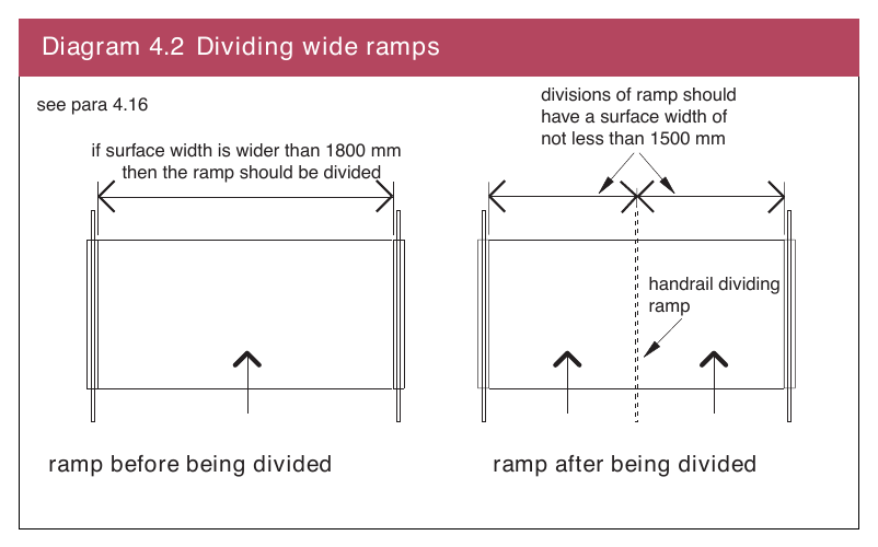
4.16A ramp or ramps and landings should have a surface width of not less than 1500 mm.
Where a handrail protrudes into the surface width of a ramp by more than 100 mm the surface width should be increased accordingly. In any case the maximum protrusion of a handrail into the surface width of a ramp should be 110 mm.
A ramp which has a surface width greater than 1800 mm, it should be divided into ramps which are not greater than 1800 mm. The minimum surface width of 1500 mm will then apply to each ramp. See Diagram 4.2.
Diagram 4.2 Dividing wide ramps
Construction of ramps
4.17The surface of a ramp should –
(a)be firm;
(b)reduce the risk of slipping; and
(c)be distinguishable, through suitable visual contrast, from that of its landings.
A ramp and its landings should have similar surface frictional characteristics.
4.18A ramp should have a raised kerb on any open side (except where it would obstruct normal use). The raised kerb should –
(a)be not less than 100 mm high; and
(b)be distinguishable, through suitable visual contrast, from that of the surface of the ramp and landings.
Page 39
#Source page 39
Landings
4.19Wheelchair users need adequate space to stop on landings, to open and pass through doors without having to reverse into circulation routes and to avoid the risk of rolling back down slopes.
A landing should be provided at the top and bottom of a ramp.
A landing should be level, however, it may have a gradient along its length not steeper than 1 in 60.
The unobstructed length of a landing should be not less than 1200 mm. Where a landing is between two ramps, it should have an unobstructed length of not less than 1500 mm.
4.20Where the ramped access or circulation route consists of three or more ramps, the intermediate landings between each ramp should have an unobstructed length of not less than 1800 mm and a surface width of not less than 1800 mm.
4.21Where a ramp does not have a clear line of sight between its top and bottom landings, it should be divided into two ramps such that there is a clear line of sight between the intermediate landing and the top and bottom landings. The intermediate landing should have an unobstructed length of not less than 1800 mm, and a surface width of not less than 1800 mm. This will allow enlarged landings to be used as passing places.
Headroom
4.22Ramps and associated landings should have a clear headroom of not less than 2000 mm over the length and width of the ramp.
Headroom is measured vertically from the slope of the ramp and the level of the landing. See Diagram 4.1.
Handrails
4.23A ramp or ramps and landings should have a suitable continuous handrail on each side complying with the provisions of paragraphs 3.39 to 3.43.
4.24A handrail should be at a height measured vertically of –
(a)not less than 900 mm and not more than 1000 mm above the surface of a ramp; and
(b)not less than 900 mm and not more than 1100 mm above the level of a landing.
4.25To give warning of a change in level i.e. the start or finish of a ramp, a handrail should extend horizontally for a distance of not less than 300 mm along the top and bottom landings of a ramp except at an intermediate landing that is not more than 1800 mm in length where it should extend the full length of the landing.
General
#Source page 40
Section 5 Guarding
General
5.1Paragraphs 5.2 to 5.4 do not apply to –
(a)guarding to a spiral or helical stair in a dwelling;
(b)guarding to a stair or a fixed ladder, in a building other than a dwelling, providing access solely for the purpose of maintenance; and
(c)a vehicle barrier.
Design of guarding
5.2The design of guarding should be such as to minimise the risk of people falling, and of rolling, sliding or slipping through gaps in a barrier.
A wall, glazing, parapet, balustrade or similar construction may serve as guarding.
A sunken area next to a building is an area adjoining the building and includes a light well, access to a basement and similar areas. Guarding should be provided to that part of a sunken area which is within 3 m of the building.
5.3The height of guarding should be measured vertically from the level of a floor or landing, the surface of a ramp or the pitch line of a flight.
However, the top of a portion of any balustrade guarding a landing at the top of a flight or ramp, may be continuous with, and at the same angle as, the top of a balustrade guarding that flight or ramp.
5.4Guarding which is provided at the locations given in Table 5.1 column (1) should be –
(a)of a height not less than that given in column (2); and
(b)capable of resisting the horizontal force given in column (3) applied at a height of 1100 mm irrespective of the actual height of the guarding (see Diagram 5.1).
| Diagram 5.1 | Guarding |
| see para 5.4 | horizontal force at 1100 mm |
Page 41
#Source page 41
| Table 5.1 Minimum height and strength of guarding | ||
|---|---|---|
| Location of guarding (1) | Minimum height+ (mm) (2) | Minimum horizontal force/metre run (kN/m) (3) |
| Dwellings | ||
| (a) guarding a flight, ramp, landing or floor within a dwelling | 900* | 0.36 |
| (b) guarding an external flight or ramp | 900 | 0.74 |
| (c) guarding a level for the purpose of maintenance | 1100 | 0.36 |
| (d) guarding not described in (a) to (c) | 1100 | 0.74 |
| Retail buildings | ||
| (a) guarding a flight or ramp | 900 | 1.50 |
| (b) guarding a level for the purpose of maintenance | 1100 | 0.36 |
| (c) guarding not described in (a) or (b) | 1100* | 1.50 |
| Other buildings | ||
| (a) guarding a flight or ramp where crowd loading will not occur | 900 | 0.74 |
| (b) guarding a flight or ramp where crowd loading† will occur | 900 | 3.00 |
| (c) guarding not described in (b) where crowd loading† will occur | 1100* | 3.00 |
| (d) guarding a floor immediately in front of fixed seating | 800 | 1.50 |
| (e) guarding a level for the purpose of maintenance | 1100 | 0.36 |
| (f) guarding not described in (a) to (e) | 1100* | 0.74 |
| Notes: + In the case of a flight or ramp the height should be measured from the pitch line of a flight or the surface of a ramp. * This may be reduced to 800 mm at openable windows or glazing at changes of level. The glazing may be designed to act as guarding, in which case separate guarding would not be required. In a roofspace conversion to a dwelling, a roof window (rooflight) that is required to comply with Part E may have this height reduced to 600 mm. † Crowd loading will occur in parts of buildings where people assemble in large numbers such as theatres, discotheques, cinemas, sports halls, assembly halls, shopping malls and similar areas. |
Infill panels
5.5
Where infill panels are provided they should be designed and constructed in accordance with the relevant clauses of BS 6180.
5.6
Where a building or part of a building is likely to be used by children under 5 years of age the guarding should be constructed so that a 100 mm diameter sphere cannot pass through any opening in it other than a triangular opening formed by a tread, a rise and the bottom edge of the guarding if that bottom edge is not more than 50 mm above the pitch line. The guarding should also be constructed so that a child cannot readily climb up it.
Guarding of spiral or helical stairs in a dwelling
#Source page 42
5.7In a dwelling, guarding to a spiral or helical stair should be designed and constructed in accordance with BS 5395: 2.
Stair or fixed ladders
5.8Guarding to a stair or a fixed ladder in a building other than a dwelling providing access solely for the purpose of maintenance should be designed and constructed in accordance with either BS 5395: 3 or BS 4211.
Vehicle barriers
5.9In a building where vehicles have access to a floor, roof or circulation ramp, guarding should be provided to any edge of such area that is above the level of any adjacent floor, ground or route for vehicles.
Such guarding should –
(a)not present a hazard e.g. by containing projections on the impact face of the barrier; and
(b)be designed and constructed in accordance with BS 6180.
Loading bays
#Source page 43
Section 6 Vehicle loading bays
Loading bays
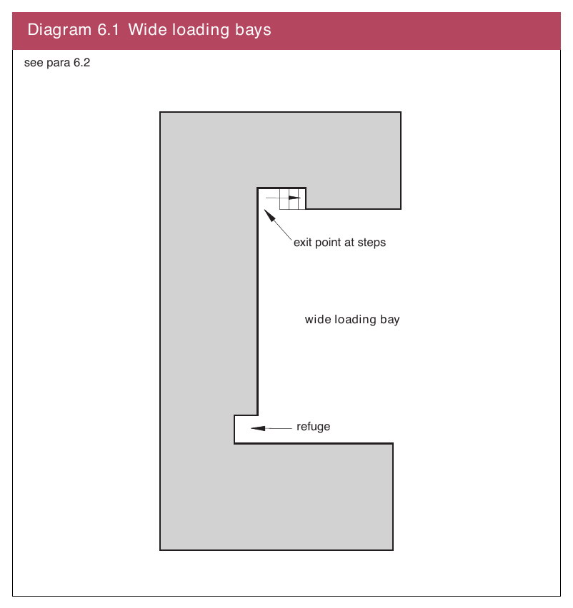
6.1A loading bay should be provided with at least one exit point from the lower level (preferably near the centre of the rear wall).
6.2A wide loading bay (with space for 3 or more vehicles) should be provided with at least –
(a)two exit points, one at each side; or
(b)an exit point and a refuge,
which people can use to avoid being struck or crushed by a vehicle. See Diagram 6.1.
Diagram 6.1 Wide loading bays
Doors and gates
#Source page 44
Section 7 Protection against impact from and trapping by doors
Doors and gates
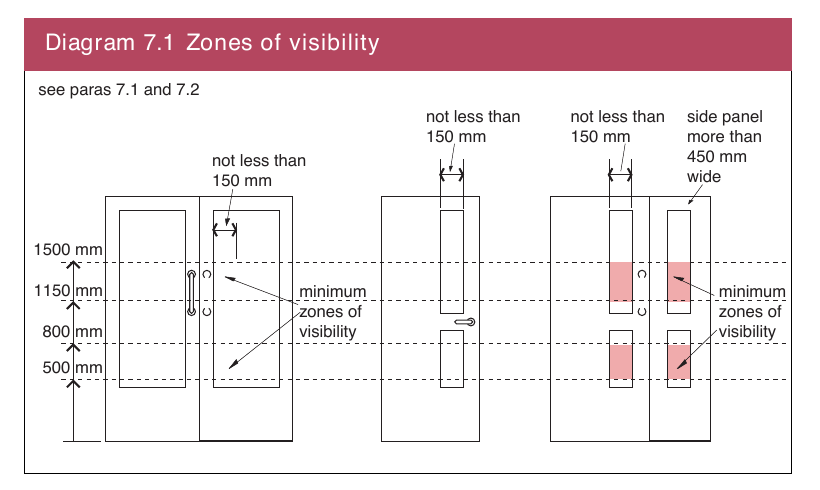
7.1
A door or gate –
(a)across a main route of travel; or
(b)which can be pushed open from either side,
should have, towards the leading edge of the door leaf, zones of visibility as shown in Diagram 7.1.
7.2Any side panel that is more than 450 mm wide and is adjacent to a door or gate, that is required by paragraph 7.1 to have zones of visibility, should also have zones of visibility. See Diagram 7.1.
Diagram 7.1 Zones of visibility
7.3A door or gate that slides or opens upwards should have a device to stop it falling in a way that may cause injury.
7.4A power operated door or gate designed and constructed for vehicular traffic should have –
(a)a pressure sensitive edge or other suitable device, which operates the power switch to prevent users being caught or trapped;
(b)a readily identifiable and accessible stop switch; and
(c)provision for manual or automatic opening in the event of a power failure.
7.5A power operated door or gate designed and constructed for pedestrian use should –
(a)incorporate a safety stop or door reactivating device to prevent the door striking a person passing through if the door begins to close; and
(b)revert to manual control or fail safe in the open position in the event of a power failure.
General
#Source page 45
Section 8 Protection from collision with open windows, skylights or ventilators
General
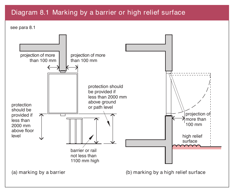
8.1Where any part of a window, skylight or ventilator, when open, could project more than 100 mm horizontally into a space less than 2000 mm above the ground or floor it should be –
(a)fitted with a suitable device to restrict the projection in normal use to not more than 100 mm; or
(b)marked by a suitable feature such as –
(i)a distinguishable barrier or rail not less than 1100 mm high;
(ii)a high relief surface; or
(iii) a landscape feature, which extends to at least the maximum projection of the window, skylight or ventilator (see Diagram 8.1).
8.2In rooms or spaces used solely for maintenance of the building and access to those rooms or spaces is infrequent, it may be appropriate only to highlight any projecting part of a window, skylight or ventilator to make it easier to see.
Diagram 8.1 Marking by a barrier or high relief surface
Page 46
#Source page 46
Appendix Publications referred to
BS 4211: 2005 Specification for permanently fixed ladders
BS 5395 Stairs
Part 2: 1984 Code of practice for the design of helical and spiral stairs AMD 6076
Part 3: 1985 Stairs, ladders and walkways. Code of practice for the design of industrial type stairs. AMD 14247
BS 6180: 2011 Barriers in and about buildings Code of practice DFP Technical Booklet B: 2012 Materials and workmanship
Page 47
#Source page 47
Technical Booklets
The following list comprises the series of Technical Booklets prepared by the Department for the purpose of providing practical guidance with respect to the technical requirements of the Building Regulations (Northern Ireland) 2012.
| Technical Booklet B | Materials and workmanship |
| Technical Booklet C | Preparation of site and resistance to |
| contaminants and moisture | |
| Technical Booklet D | Structure |
| Technical Booklet E | Fire safety |
| Technical Booklet F1 | Conservation of fuel and power in |
| dwellings | |
| Technical Booklet F2 | Conservation of fuel and power in buildings other |
| than dwellings | |
| Technical Booklet G | Resistance to the passage of sound |
| Technical Booklet H | Stairs, ramps, guarding and protection from |
| impact | |
| Technical Booklet J | Solid waste in buildings |
| Technical Booklet K | Ventilation |
| Technical Booklet L | Combustion appliances and fuel storage |
| systems | |
| Technical Booklet N | Drainage |
| Technical Booklet P | Sanitary appliances, unvented hot water storage |
| systems and reducing the risk of scalding | |
| Technical Booklet R | Access to and use of buildings |
| Technical Booklet V | Glazing |
Any person who intends to demonstrate compliance with the Building Regulations by following the guidance given in a Technical Booklet is advised to ensure that the guidance is current on the date when plans are deposited or notice given to the district council.