Northern Ireland Technical booklet L
Technical Booklet L
Library captured 10 September 2026 · Source updated 22 August 2026
● Finance and ● Personnel
#Source page 1
Department of
● Finance and ● Personnel
G u i d a n c e
Te c h n i c a l B o o k l e t
L
Combustion appliances and fuel storage systems
October 2012
Page 2
#Source page 2
Contents page
| Introduction | |
|---|---|
| Technical Booklets | 3 |
| This Technical Booklet | 3 |
| Protected buildings | 4 |
| Other legislation | 4 |
| Part L Regulations | 7 |
| Guidance – Performance and introduction to provisions | 10 |
| Section 1 General | |
| Definitions | 13 |
| Section 2 General provisions for combustion appliances | |
| Air supply and ventilation | 21 |
| Flues and chimneys | 25 |
| Dry lining around fireplace openings | 33 |
| Condition of combustion installations at completion | 33 |
| Notice plates for hearths and flues | 33 |
| Access to combustion appliances for maintenance | 34 |
| Detection and warning of the presence of carbon monoxide | 35 |
| Section 3 Solid fuel burning appliances (including solid biofuel) with a rated | |
| heat output up to 50 kW | |
| Air supply to appliances | 36 |
| Flues and chimneys | 37 |
| Hearths | 46 |
| Fireplace recesses and prefabricated appliance chambers | 50 |
Page 3
#Source page 3
Section 4 Gas burning appliances with a rated heat input up to 70 kW (net)
Gas burning appliances 53
Air supply and ventilation 55
Flues and chimneys 58
Bases for back boilers 64
Hearths for gas burning appliances 65
Shielding of appliances 66
Section 5 Oil burning appliances (including liquid biofuel) with a rated heat output up to 45 kW
Class of oil 67
Appliances fitted in bedrooms, bathrooms and shower rooms 67
Air supply and ventilation 67
Flues and chimneys 69
Shielding of oil-fired appliances 77
Section 6 Liquid fuel (including liquid biofuel) storage and supply
Oil storage installations 78
Liquefied Petroleum Gas (LPG) storage installations 80
Appendix A Inspection and testing of flues, chimneys and flue pipes 83
Appendix B Informative – European chimney designations 87
Appendix C Assessing air permeability of older dwellings in relation to permanent ventilation requirements 91
Appendix D Informative – LPG cylinders 92
Appendix E Publications referred to 93
Technical Booklets
#Source page 4
Introduction
Technical Booklets
This Technical Booklet, which takes effect on 31st October 2012, is one of a series that has been prepared by the Department of Finance and Personnel (the Department) for the purpose of providing practical guidance with respect to the technical requirements of the Building Regulations (Northern Ireland) 2012 (the Building Regulations).
At the back of each Technical Booklet is a list of all the Technical Booklets that have been prepared and published by the Department for this purpose.
The guidance given in a Technical Booklet includes performance standards and design provisions relating to compliance with specific aspects of the Building Regulations for the more common building situations.
If the guidance in a Technical Booklet is followed there will be a presumption of compliance with the requirements of those Building Regulations covered by that guidance. However, this presumption can be overturned, so simply following the guidance does not guarantee compliance. For example, if a particular circumstance is not one of the more common building situations the design provisions given in the Technical Booklet may not be appropriate.
There are likely to be alternative ways of demonstrating compliance with the relevant requirements of the Building Regulations other than by following a design provision given in a Technical Booklet. There is therefore no obligation to adopt any particular provision set out in a Technical Booklet, should you decide to comply in some other way. However, you will have to demonstrate that your alternative solution meets the relevant requirements of the Building Regulations by those other means.
This Technical Booklet
Requirements
The guidance contained in this Technical Booklet relates only to the requirements of regulations 70, 71, 72, 73, 74, 75, and 76. The work will also have to comply with all other relevant requirements of the Building Regulations.
Materials and workmanship
Any building work which is subject to requirements imposed by Part A of the Building Regulations should be carried out in accordance with regulation 23 of those regulations. Guidance on meeting these requirements for materials and workmanship is given in Technical Booklet B which supports Part B.
Protected buildings
#Source page 5
The Building Regulations are made for specific purposes, primarily securing the health, safety, welfare and convenience of people and for the conservation of fuel and power. Standards and technical approvals are relevant guidance to the extent that they relate to these purposes. However, they may also address other aspects of performance such as serviceability, or aspects which although they relate to health and safety are not covered by the Building Regulations.
Named standards
Where this Technical Booklet makes reference to a named standard, the relevant version of the standard is the one listed in Appendix E. However, if this version has been replaced or updated by the issuing standards body, the new version may be used as a source of guidance provided that it continues to address the relevant requirements of the Building Regulations.
Diagrams
The diagrams in this Technical Booklet supplement the text. They do not show all the details of construction and are not intended to illustrate compliance with any other requirement of the Building Regulations. They are not necessarily to scale and should not be used as working details.
Protected buildings
District councils have a duty to take account of the desirability to preserve the character of protected buildings when carrying out their functions under Building Regulations. Therefore, where work is to be carried out to a protected building to comply with Part L or any other Part of the Building Regulations, special consideration may be given to the extent of such work for compliance where it would unacceptably alter the character or appearance of the building. Protected buildings are defined in Article 3A(2) of the Building Regulations (Northern Ireland) Order 1979 (as amended).
Other legislation
The provisions of this Technical Booklet relate to the requirements of Building Regulations and do not include measures which may be necessary to meet the requirements of other legislation. Such other legislation may operate during the design or construction stages or when a building is brought into use and can extend to cover aspects which are outside the scope of the Building Regulations.
The Workplace (Health, Safety and Welfare) Regulations (Northern Ireland) 1993
The Workplace (Health, Safety and Welfare) Regulations (Northern Ireland) 1993 (the Workplace Regulations) contain some requirements which affect building design. The main requirements are now covered by the Building Regulations, but for further information see – The Workplace Regulations and the Workplace Health, Safety and Welfare Approved Code of Practice.
Page 6
#Source page 6
The Workplace Regulations apply to the common parts of flats and similar buildings if people such as cleaners, wardens and caretakers are employed to work in these common parts. Where the requirements of the Building Regulations that are covered by Part L do not apply to dwellings, the provisions may still be required in the situations described above in order to satisfy the Workplace Regulations.
The Clean Air (Northern Ireland) Order 1981
Under the Clean Air (Northern Ireland) Order 1981 a district council may declare the whole or part of a district of the council to be a smoke control area. It is an offence to emit smoke from a chimney of a building, from a furnace or from any fixed boiler if located in a designated smoke control area unless an authorised fuel is used. It is also an offence to acquire an ‘unauthorised fuel’ for use within a smoke control area unless it is used in an ‘exempt’ appliance (‘exempted’ from the controls which generally apply in the smoke control area).
Authorised fuels are fuels which are authorised under the Clean Air (Northern Ireland) Order. These include inherently smokeless fuels such as gas, electricity and anthracite together with specified brands of manufactured solid smokeless fuels. These fuels have passed tests to confirm that they are capable of burning in an open fireplace without producing smoke.
Exempt appliances are appliances (ovens, wood burners, boilers and stoves) which have been exempted by the Clean Air (Northern Ireland) Order. These have passed tests to confirm that they are capable of burning an unauthorised or inherently smoky solid fuel without emitting smoke.
Gas Safety (Installation and Use) Regulations (Northern Ireland) 2004
All combustion installations must be accommodated in ways that meet the requirements of the Building Regulations. However, gas installations also have to comply with the Gas Safety (Installation and Use) Regulations (Northern Ireland) 2004 which require professional work to be undertaken by a member of a class of persons approved by the Health and Safety Executive Northern Ireland (HSENI).
The Gas Safety (Installation and Use) Regulations (Northern Ireland) 2004 cover the safe installation of gas fittings, appliances and flues. The following paragraphs give an outline of some of the main requirements of those Regulations but for further information reference should be made to the Health and Safety Commission's Approved Code of Practice and Guidance L56.
The Gas Safety (Installation and Use) Regulations (Northern Ireland) 2004 require that –
(a)gas fittings, appliances and gas storage vessels must only be installed by a person with the required competence;
(b)any person having control to any extent of gas work must ensure that the person carrying out that work has the required competence; and
(c)any gas installation business, whether an employer or self-employed, must be a member of a class of persons approved by the HSENI.
Page 7
#Source page 7
The Gas Appliances (Safety) Regulations 1995
The Gas Appliances (Safety) Regulations 1995 require that particular combinations of appliance, flue box (where required) and flue must be selected from those stated in the manufacturer’s instructions as having been shown to be safe by a Notified Body.
Control of Oil Pollution
The control of pollution of groundwater and waterways within Northern Ireland is currently covered by The Groundwater Regulations (Northern Ireland) 2009 and The Water (Northern Ireland) Order 1999.
This legislation is enhanced by The Control of Pollution (Oil storage) Regulations (Northern Ireland) 2010 which covers above ground oil storage installations, on premises used wholly or mainly as one or more private dwellings, storing more than 3,500 litres of oil. It will also cover any industrial, commercial and institutional sites storing more than 200 litres of oil.
Liquefied Petroleum Gas (LPG) Installations
LPG installations are controlled by legislation enforced by the HSENI or its agents. Factors that determine the amount of building work necessary for a LPG storage installation to comply include its capacity, whether or not tanks are installed above or below ground and the nature of the premises they serve. LPG storage installations should be shown to comply with the legislation by constructing it in accordance with:
(a)LPGA Code of Practice 1: Parts 1 to 4; or
(b)LPGA Code of Practice 24: Use of LPG Cylinders: Part 1: The use of propane cylinders at residential premises where applicable.
PART L
#Source page 8
Part L Regulations
Part L (comprising regulations 69 to 77) of the Building Regulations, which sets out the requirements for combustion appliances and fuel storage systems, has been replicated below for the convenience of the user of this Technical Booklet and is taken directly from the Building Regulations (Northern Ireland) 2012.
Any person who intends to demonstrate compliance with the Building Regulations by following the guidance given in this Technical Booklet is advised to ensure that the regulations below, are current on the date when plans are deposited or notices given to the district council.
As Part A (comprising regulations 1 to 21) of the Building Regulations sets out the interpretation along with the procedural requirements relating to the application of the regulations, the Department advises that all Parts of the Building Regulations are read in conjunction with Part A of those regulations.
The Building Regulations (Northern Ireland) 2012 and any subsequent amendment may be viewed by following the links from the Department’s website at “www.buildingregulationsni.gov.uk”.
PART L
Combustion appliances and fuel storage systems
Application and interpretation
69.—(1) Any provision in regulations 70 to 74 and 77 which applies to a combustion appliance, shall also apply where solid fuel is intended to burn directly on a hearth without the installation of any appliance.
(2)Regulation 72 shall not apply to a combustion appliance designed solely for cooking purposes.
(3)Regulation 75 shall only apply to a liquid fuel storage tank and connecting pipework located outside the building, which serves a fixed combustion appliance within the building and which is—
(a)a fixed oil storage tank with a capacity greater than 90 litres; or
(b)a fixed liquefied petroleum gas storage tank with a capacity greater than 150 litres.
(4)Regulation 76 shall only apply to an above ground fixed oil storage tank, which serves a dwelling and to which any one of the following applies—
(a)it has a capacity of more than 2500 litres but less than 3500 litres;
(b)it is located within 10 m of inland freshwaters or coastal waters;
(c)it is located within 50 m of a source of potable water, such as a well, bore-hole or spring;
(d)it is located where spilled oil from the installation could reach the waters in (b) or (c) by running across hard ground;
(e)it is located where spillage could run into an open drain or loose fitting manhole cover; or
(f)it is located where the tank vent pipe outlets cannot be seen from the intended filling point.
Air supply
#Source page 9
(5)In this Part—
“Combustion appliance” means a fixed appliance (including a cooker) which—
(a)is designed to burn solid fuel, gas or oil; or
(b)is an incinerator.
Air supply
70.A combustion appliance shall be so installed as to receive a sufficient supply of air to ensure the safe and efficient operation of the combustion appliance and any connected flue.
Discharge of products of combustion
71.A combustion appliance shall be so installed and any connected flue-pipe, flue or chimney shall be so constructed and installed as to ensure that the products of combustion are discharged to the external air without causing a hazard to the health of any person.
Warning of the presence of carbon monoxide gas
72.When a combustion appliance is installed in a dwelling, reasonable provision shall be made to detect and give warning of the presence of carbon monoxide gas at levels harmful to people.
Protection of people and buildings
73.—(1) A combustion appliance shall be so installed and any connected flue-pipe, flue or chimney shall be so constructed and installed as to ensure that their use shall not cause—
(a)burns to any person; or
(b)damage to a building by heat or fire.
(2) A hearth or fireplace recess shall be so designed and constructed as to prevent damage to a building by heat or fire as a result of the operation of a combustion appliance installed in it or on it.
Provision of information
74.Where a hearth, fireplace, flue or chimney is provided or extended, a durable notice containing information on its performance capabilities shall be affixed to a suitable place in the building for the purpose of enabling a compatible combustion appliance to be safely connected to that hearth, fireplace, flue or chimney.
Protection of liquid fuel storage tanks
75.Reasonable provision shall be made to ensure that a liquid fuel storage tank and connecting pipework is so constructed and separated from adjacent buildings and the boundary of the premises as to reduce to a reasonable level the risk of the fuel contained inside it igniting in the event of a fire occurring in adjacent buildings or premises.
Protection against pollution
76.An oil storage tank and connecting pipework shall be so constructed and protected as to minimise the risk of an escape of oil causing pollution to the environment.
Prevention of smoke emission
#Source page 10
77.A combustion appliance installed in a building for the purpose of heating or cooking, and which discharges its combustion products to the external air shall be capable of, or readily adaptable to, the burning of fuel smokelessly, unless it is—
(a)a furnace which complies with Article 5 of the Clean Air (Northern Ireland) Order 1981(a) (which requires that new furnaces shall so far as practicable be smokeless); or
(b)an appliance of a class exempted conditionally or unconditionally from the provisions of Article 17 of the Clean Air (Northern Ireland) Order 1981 (which relates to smoke control areas) by any order for the time being in force under paragraph (7) of that Article.
(a) S.I. 1981 No.158 (N.I. 4)
General
#Source page 11
Guidance – Performance and introduction to provisions
General
0.1This Technical Booklet gives guidance on how to satisfy the requirements of Part L. Although Part L applies to the accommodation of any combustion installation and liquid fuel storage system within the limits as applied by regulation 69 in Part L, the guidance in this Technical Booklet has been prepared mainly with domestic type installations in mind.
For installations subject to the requirements of Part L but outside the provisions of this Technical Booklet, such as incinerators or installations with higher ratings than those given, specialist guidance may be necessary. However, some larger installations may be shown to comply by adopting the relevant recommendations to be found in the Chartered Institution of Building Services Engineers (CIBSE) Guide B and practice standards produced by the British Standards Institution (BSI) and the Institution of Gas Engineers & Managers (IGEM).
Combustion appliances and provision of information
Performance (regulations 70, 71, 72, 73 and 74 in Part L)
0.2It is the view of the Department that the requirements of regulations 70, 71, 72, 73 and 74 in Part L will be met if the building provides for the safe accommodation of combustion appliances which –
(a)enables the admission of sufficient air for –
(i)the proper combustion of fuel and the operation of flues; and
(ii)the cooling of appliances where necessary;
(b)enable normal operation of appliances without the products of combustion becoming a hazard to health;
(c)incorporate an appropriate means of detection and warning of a release of carbon monoxide;
(d)enable normal operation of appliances without their causing danger through damage by heat or fire to the fabric of the building;
(e)have been inspected and tested to establish suitability for the purpose intended; and
(f)have been labelled to indicate performance capabilities.
Introduction to provisions in Section 2
0.3The guidance in Section 2 sets out the general provisions for combustion appliances that should be met, specifically air supply, flues, access for maintenance, notice plates for hearths and flues, and detection and warning of the presence of carbon monoxide.
Protection of liquid fuel storage tanks and protection against pollution
#Source page 12
Introduction to provisions in Section 3
0.4Section 3 gives guidance on the installation of a solid fuel burning combustion appliance in relation to specific provisions for air supply, flues, chimneys and hearths.
Introduction to provisions in Section 4
0.5Section 4 sets out provisions that should be met for gas burning appliances specifically air supply, flued and flueless appliances, hearths and shielding.
Introduction to provisions in Section 5
0.6The guidance in Section 5 is to ensure that where an oil burning appliance is installed specific provision of air supply, flues, chimneys, hearths and shielding is made.
Alternative approach
0.7The requirements of regulations 70, 71 and 73 in Part L could also be met by adopting the relevant recommendations in the publications listed below to achieve an equivalent level of performance to that obtained by following the guidance in this Technical Booklet –
BS 8303: Part 1
BS 5440: Part 2
BS 5410: Part 1.
Protection of liquid fuel storage tanks and protection against pollution
Performance (regulation 75 in Part L)
0.8It is the view of the Department that the requirements of regulation 75 in Part L will be met where oil and LPG fuel storage installations, including the pipework connecting them to the combustion appliances in the buildings they serve, are located and constructed so that they are reasonably protected from fires which may occur in buildings within the boundary or, where the installation is close to the boundary, either protected or separated from the boundary of the site.
Performance (regulation 76 in Part L)
0.9It is the view of the Department that the requirements of regulation 76 in Part L will be met if an above ground oil storage tank/s serving a dwelling –
(a)incorporates secondary containment; and
(b)has any ancillary equipment and pipework connecting it to a combustion appliance reasonably resistant to physical damage and corrosion.
Page 13
#Source page 13
Introduction to provisions in Section 6
0.10Section 6 gives guidance –
(a)on the measures to be taken to protect an oil or LPG fuel storage installation –
(i)from a fire in the building it serves; and
(ii)where the installation is located adjacent to the boundary of the site, and
(b)on the construction of oil storage tanks.
Alternative approach
0.11The requirements for an oil storage tank could also be met by adopting the relevant recommendations in BS 5410: Part 1 to achieve an equivalent level of performance to that obtained by following the guidance in this Technical Booklet.
Definitions
#Source page 14
Section 1 General
1.1This Technical Booklet gives provisions which if followed, should comply with the functional requirements of Part L of the Building Regulations and includes the admission of sufficient air into the building to enable the proper combustion of fuels and operation of flues. Technical Booklet K gives guidance on complying with Part K (Ventilation). Part K is concerned with providing adequate ventilation to limit the accumulation of moisture and pollutants which could become a hazard to the health of the users of a building.
Definitions
1.2In this Technical Booklet the following definitions apply –
Appliance compartment – an enclosure specifically constructed or adapted to accommodate one or more gas or oil-fired appliances.
Balanced compartment – a method of installing an open-flued appliance into a compartment which is sealed from the remainder of the building and whose ventilation is so arranged in conjunction with the appliance flue as to achieve a balanced flue effect.
Balanced flue appliance – a type of room-sealed appliance that draws its combustion air from a point outside the building adjacent to the point at which the combustion products are discharged, the inlet and outlet being so disposed that wind effects are substantially balanced.
Boundary – has the meaning assigned to it by regulation 2 in Part A of the Building Regulations.
Capacity (of an oil or gas tank) – the nominal volume of the tank as stated by the manufacturer.
Page 15
#Source page 15
Diagram 1.1 Chimneys and flues
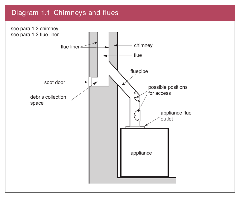
Chimney – a structure consisting of a wall or walls enclosing one or more flues. See Diagram 1.1.
Combustion appliance – has the meaning assigned to it by regulation 69 in Part L of the Building Regulations.
Designation – BS EN 1443 expresses the performance characteristics of a flue or its components, as assessed in accordance with an appropriate European product standard, by means of a code such as “EN 1234 T400 P1 S W 1 R22 C50”. This code is known as the designation for the flue or its components. See Appendix B.
Draught break – an opening formed by a factory-made component into any part of the flue serving an open-flued appliance.
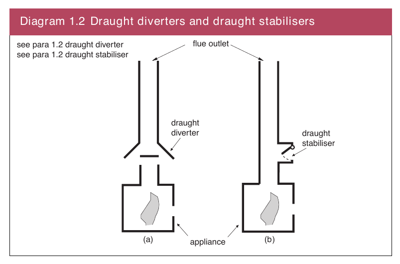
Draught diverter – a form of draught break intended to prevent conditions in the main length of flue from interfering with the combustion performance of an open-flued appliance. See Diagram 1.2(a).
Draught stabiliser – a factory-made counter-balanced flap device admitting air to the flue, from the same space as the combustion air, to prevent excessive variations in the draught. See Diagram 1.2(b).
Dwelling – has the meaning assigned to it by regulation 2 in Part A of the Building Regulations.
Page 16
#Source page 16
Diagram 1.2 Draughtdiverters and draught stabilisers
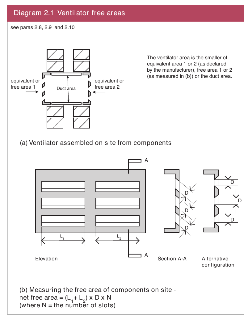
Equivalent area – the area of a sharp-edged circular orifice which would pass the same air flow rate at the same applied pressure difference as the product or device being tested. The equivalent area of a simple ventilator should be less than the geometrical free area and for complex products may be significantly less.
Factory-made metal chimneys (also known as system chimney) – prefabricated chimneys that are commonly manufactured as sets of components for assembly on site (although they can be supplied as one unit), having the performance appropriate for the intended appliance.
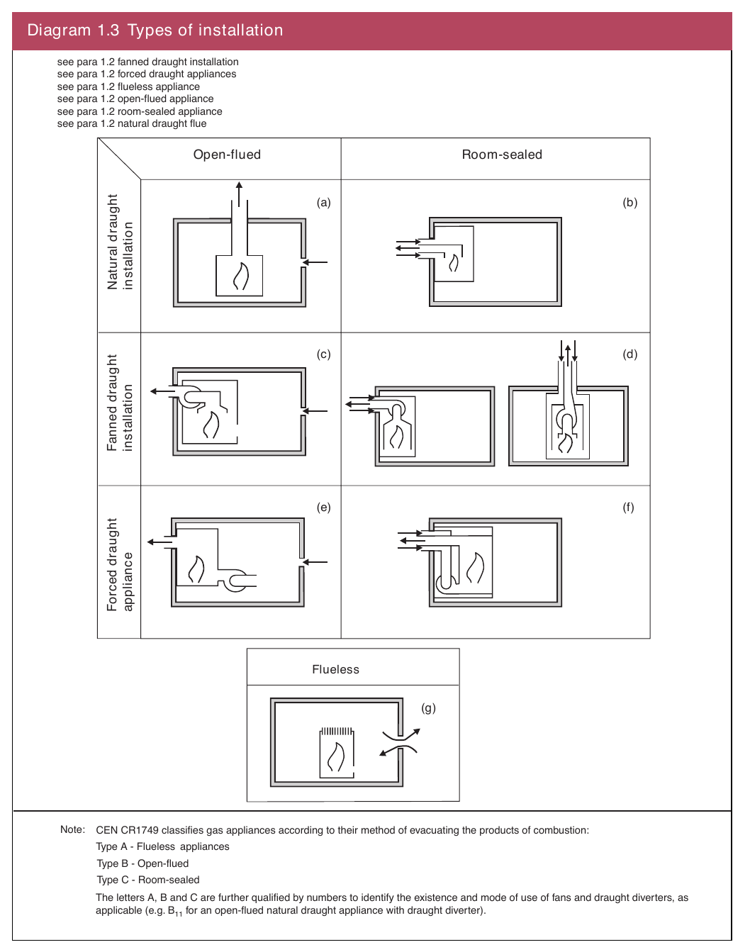
Fanned draught installation – the proper discharge of the flue gases depends upon the operation of a fan, which may be separately installed in the flue or may be an integral part of the combustion appliance. See Diagram 1.3.
Fire compartment – a building or part of a building comprising one or more rooms, spaces or storeys, constructed to prevent the spread of fire to or from another part of the same building, or an adjoining building. A roof space above the top storey of a fire compartment is included in that fire compartment.
Page 17
#Source page 17
Diagram 1.3 Types of installation
Page 18
#Source page 18
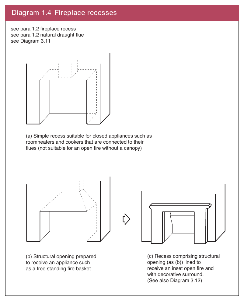
Fireplace recess – a structural opening (sometimes called a builder's opening) formed in a wall or in a chimney breast, from which a chimney leads and which has a hearth at its base. See Diagram 1.4.
Diagram 1.4 Fireplace recesses
Fire resistance (of a component or construction) – a measure of its ability to withstand the effects of fire in one or more ways for a stated period of time. Provisions on determination of performance in terms of fire resistance are given in Technical Booklet E (Fire safety).
Fire wall – a method of shielding a fuel tank from the thermal radiation from a fire in the adjoining building or boundary.
Flue block chimney systems – a set of factory-made components made from precast concrete, clay or other masonry units that are designed for assembly on site to provide a complete chimney having the performance appropriate for the intended appliance.
Flue box – a factory-made unit, usually made of metal, which is similar to a prefabricated appliance chamber except that it is designed to accommodate a gas-burning appliance in conjunction with a factory-made chimney.
Page 19
#Source page 19
Flueless appliance – one which is designed to be used without connection to a flue. See Diagram 1.3(g).
Flue liner – the wall of the chimney that is in contact with the products of combustion (see Diagram 1.1), such as a concrete flue liner, the inner liner of a factory-made chimney system or a flexible liner fitted into an existing chimney.
Flue outlet – the point at which the products of combustion are discharged from the flue to the outside atmosphere, such as the top of a chimney pot or flue terminal.
Flue pipe – a pipe, either single walled (bare or insulated) or double walled, which connects a combustion appliance to a flue in a chimney.
Forced draught appliances – an appliance with a fan that provides the combustion air, common in oil-fired and many gas-fired boilers. See Diagram 1.3.
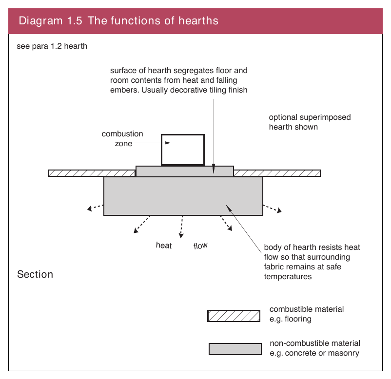
Hearth – a base intended to safely isolate a combustion appliance from people, combustible parts of the building fabric and soft furnishings. See Diagram 1.5.
Diagram 1.5 The functions of hearths
Materials – has the meaning assigned to it by regulation 2 in Part A of the Building Regulations.
Page 20
#Source page 20
Natural draught flue – the combustion products flow into the flue as a result of the buoyancy force produced due to the difference between the temperature of the gases within the flue and the temperature of the ambient air. Draught increases with the height of the flue. Except for those balanced flue appliances which are designed to discharge directly through the wall adjacent to the appliance, a satisfactory natural draught requires an essentially vertical run of flue. See Diagram 1.3(a) and (b).
Non-combustible material – This is the highest level of reaction to fire performance. A non-combustible material is –
(a)a material classified as non-combustible in tests following the procedures in BS 476: Part 4;
(b)a material which when tested to BS 476: Part 11 does not flame nor cause any rise in temperature on either the centre (specimen) or furnace thermocouples; or
(c)a material classified as Class A1 in accordance with BS EN 13501
Fire classification of construction products and building elements:
Part 1: Classification using test data from reaction to fire tests when tested to –
(i)BS EN ISO 1182 Reaction to fire tests for building products – Non-combustibility test; and
(ii)BS EN ISO 1716 Reaction to fire tests for building products – Determination of the heat of combustion.
Typical examples of such materials to be found in buildings include totally inorganic materials such as concrete, fired clay, ceramics, metals, plaster and masonry containing not more than 1% by weight or volume of organic material. (Use in buildings of combustible metals such as magnesium-aluminium alloys should be assessed in each individual case).
Notified Body – for the purposes of the Gas Appliances (Safety) Regulations (1995), means –
(a)a body which is approved by the Secretary of State for Trade and Industry as being competent to carry out the required Attestation procedures for gas appliances and whose name and identification number has been notified by him/her to the Commission of the European Community and to other member States in accordance with the Gas Appliances (Safety) Regulations 1995; or
(b)a body which has been similarly approved for the purposes of the Gas Appliances Directive by another member State and whose name and identification number has been notified to the Commission and to other member States pursuant to the Gas Appliances Directive.
Open-flued appliance – one which draws its combustion air from the room or space within which it is installed and which requires a flue to discharge its products of combustion to the outside air. See Diagram 1.3(a), (c) and (e).
Prefabricated appliance chamber – a set of factory-made pre-cast concrete components designed to provide a fireplace recess to accommodate an appliance such as a stove, and incorporates a gather when used with an open fire.
Page 21
#Source page 21
Rated heat input (sometimes shortened to rated input) – for a gas appliance means the maximum heat input rate (kW) at which it can be operated, as declared on the appliance data plate.
Rated heat output – for an oil or solid fuel appliance means the manufacturer’s maximum declared energy output rate (kW) for the appliance as declared on the appliance data plate.
Room-sealed appliance – an appliance with a combustion system that is sealed from the room in which it is located, and which obtains air for combustion, from a ventilated uninhabited space within the building, or directly from the open air outside the building and vents the products of combustion directly to the open air outside the building. See Diagram 1.3(b),
(d) and (f).
Separated part – of a building means a form of compartmentation in which part of a building is separated from another part of the same building by a compartment wall. (The wall runs the full height of the part and is in one vertical plane.)
Solid biofuel – a solid fuel derived from plants and trees. It can include logs, wood chips, wood pellets and other processed plant material.
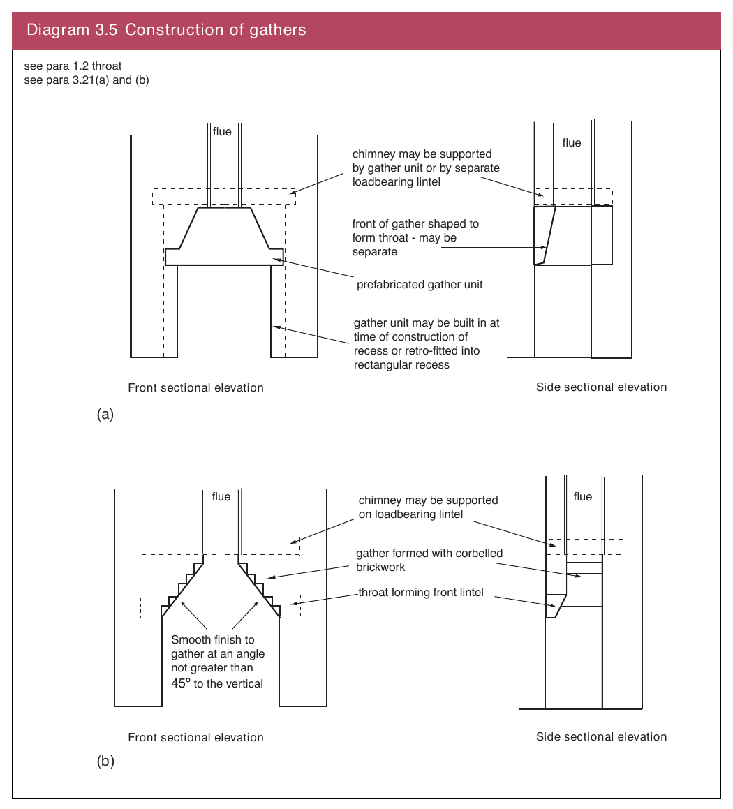
Throat – a contracted part of the flue between a fireplace recess and its chimney. See Diagram 3.5.
Air supply and ventilation
#Source page 22
Section 2 General provisions for combustion appliances
Air supply and ventilation
Air supply for combustion appliances
2.1All combustion appliances require the supply of air for combustion and to ensure the proper operation of the flue. A flueless appliance also needs air to ensure that the products of combustion are safely dispersed to the outside air. In some cases, combustion appliances may also require air for cooling control systems and/or to ensure that casings remain safe to touch.
2.2The size of air vent required, which is dependent upon the type of fuel burned, is given in Sections 3, 4 and 5 and is for one combustion appliance only. If a room contains more than one combustion appliance the air supply provisions will have to be increased.
Ventilation of appliance compartments
2.3An appliance compartment that encloses an open-flued appliance should be provided with an air vent(s) large enough to admit all of the air required for combustion and the proper operation of the flue.
2.4High and low level vents should be provided where the combustion appliance requires cooling air and the appliance compartment should be large enough to enable the air to circulate effectively.
2.5Where the combustion appliance is to be installed within a balanced compartment special provisions will be necessary. In such circumstances the manufacturer's instructions for the combustion appliance and ventilation system should be followed.
Ventilation via other rooms or spaces
2.6If a combustion appliance is room-sealed but takes its combustion air from another space in the building, or if a flue has a permanent opening to another space in the building, that space should have ventilation openings directly to the outside air.
2.7Where a flued appliance is supplied with combustion air through an air vent(s) that opens into an adjoining room or space, the adjoining room or space should have air vent openings of at least the same size directly to the outside air.
An air vent(s) for a flueless appliance should always open directly to the outside air.
2.8Where ventilation is to be provided via a single proprietary assembly the equivalent free area of the air vent should be taken to be the manafacturer’s value. The manufacturer may call this a free area or equivalent free area. See Diagram 2.1(a).
2.11 Grilles or meshes protecting air vents from the entry of animals or birds should have individual aperture dimensions of not less than 5 mm.
#Source page 23
2.9Where two or more components are to be used to provide a non-proprietary ventilation assembly, the assembly should be kept as simple and smooth as possible. The assembly should be taken to have an equivalent area equal to that of the component with the smallest equivalent area in the assembly.
2.10The equivalent area stated in the ventilator manufacturer’s literature or marked on the air vent should be used whenever it is available, as this can differ considerably from the free area measured at one end of the air vent. When this is not available the equivalent area of a simple ventilator with no internal baffles can be taken as the total unobstructed cross-sectional area, measured in the plane where this area is at a minimum and at right angles to the direction of air flow. For an airbrick, grille or louvre with apertures no smaller than 5 mm, it should be the aggregate free area of the individual apertures as shown in Diagram 2.1.
2.11 Grilles or meshes protecting air vents from the entry of animals or birds should have individual aperture dimensions of not less than 5 mm.
Diagram 2.1 Ventilator free areas
Page 24
#Source page 24
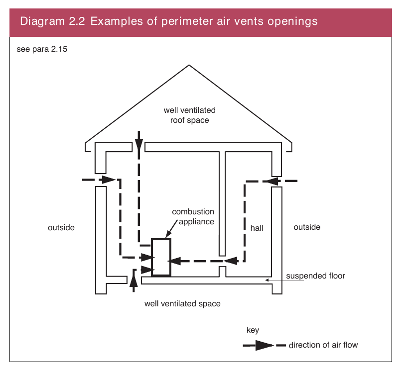
Diagram 2.2 Examples of perimeter air vents openings
Permanently open ventilation of rooms
2.12A room containing an open-flued appliance must receive a continuous supply of air from outside. The volume of air required depends on the type and rating of the appliance. This normally means the installation of permanently open air vents into that room.
2.13A permanently open air vent should be non-adjustable and be positioned where it is unlikely to become blocked. It should be so installed that the building occupants are not provoked into sealing it against draughts or noise.
It should not be positioned in a fire resisting wall other than an external wall that is not part of an external wall shielding a LPG or oil storage tank. A permanently open air vent should not be located within a fireplace recess.
2.14A permanently open air vent should be sized so that the free area, or the equivalent free area of a more complex design, is sufficient for the appliance to be installed, taking account where necessary of obstructions such as grilles and anti vermin mesh.
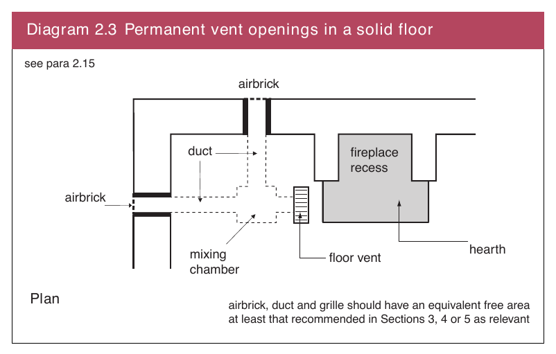
2.15Any discomfort from cold draughts can be avoided by placing the air vent close to the appliance, drawing air from other parts of the building or by ensuring a good mix of the incoming cold air by placing the air vent close to the ceiling, see Diagrams 2.2 and 2.3. In a noisy area, it may be necessary to install proprietary noise attenuated air vents to limit the entry of noise into the building but these should not diminish the required air supply. The location of air vents should not breach the requirements of Part E of the Building Regulations.
Page 25
#Source page 25
Diagram 2.3 Permanent vent openings in a solid floor
Interaction of mechanical extract ventilation and open-flued combustion appliances
2.16Extract fans lower the pressure in a building and this can cause the spillage of combustion products from an open-flued appliance.
2.17In a building where it is intended to install an open-flued appliance and an extract fan, the combustion appliance should operate safely whether or not the fan is running. To minimise the risk of spillage of flue gas the following provisions should apply –
(a)for a gas appliance – where a room contains an open-flued appliance, the room extract fan rate should not exceed 20 litres/second (72 m3/hour), and a spillage test as recommended in BS 5440: 1 should be carried out.
(b)for oil appliances – where a room contains an open-flued appliance the extract rate should be limited to 40 litres/second for an appliance with a pressure jet burner and 20 litres/second for an appliance with a vaporising burner. When spillage or flue draught interference is identified, it may be necessary to add additional ventilation to the room or space. A flue draught interference test for oil-fired appliances as described in OFTEC Technical Books 2 and 5 should be carried out.
(c)for a solid fuel appliance – a room extract fan should not be installed in the same room. If mechanical extraction is unavoidable then seek specialist advice from a mechanical/services engineer to ensure safe operation of the appliance.
(d)for commercial and industrial installations – specialist advice from a mechanical/services engineer may be necessary with regard to the possible need for the interlocking of gas heaters and any mechanical ventilation system.
Flues and chimneys
#Source page 26
Provision of flues
2.18This Technical Booklet provides guidance on how to construct a flue or chimney that serves only one appliance. A flue designed to serve more than one appliance should follow the recommendations of BS 5410: Part 1 for oil and BS 5440: Part 1 for gas-fired combustion appliances. Each solid fuel appliance should have its own flue.
2.19A combustion appliance, other than a flueless appliance, should incorporate or be connected to a suitable flue that discharges to the outside air.
Condensates in flues
2.20A flue should provide satisfactory control of water condensation. This can be achieved by adopting one of the following provisions –
(a)the flue for a non-condensing combustion appliance should be insulated so that flue gas does not condense during normal operation; or
(b)the flue for a condensing combustion appliance should be lined with components that are impervious to condensates and resistant to corrosion (BS EN 1443 ‘W’ designation) avoiding ledges, crevices, etc.
A condensing combustion appliance should have a suitable drain fitted for the disposal of condensate. Guidance on the disposal of such condensate is given in Technical Booklet N.
Construction of masonry chimneys
2.21A new chimney should be constructed with a flue liner and masonry suitable for the intended application.The following liners are suitable for a solid fuel appliance as well as being generally suitable for other fuels –
(a) a liner with a performance that is equal to that corresponding to the designation T400 N2 D 3 G, as described in BS EN 1443, such as –
(i)clay flue liners, with rebates or sockets for jointing, meeting the requirements for Class A1 N1 or Class A1 N2 as described in BS EN 1457;
(ii)concrete flue liners meeting the requirements for the classification Type A1, A2, B1 or B2 as described in BS EN 1857; or
(iii) other products that meet the designation above.
2.22A liner should be installed in accordance with the manufacturer's instructions. Appropriate components should be selected to form the flue without cutting and to keep joints to a minimum. Bends and offsets should only be formed with matching factory-made components. Liners should be placed with the sockets or rebate ends uppermost to contain moisture and other condensates in the flue. Joints should be sealed with fire cement, refractory mortar or installed in accordance with their manufacturer's instructions.
Page 27
#Source page 27
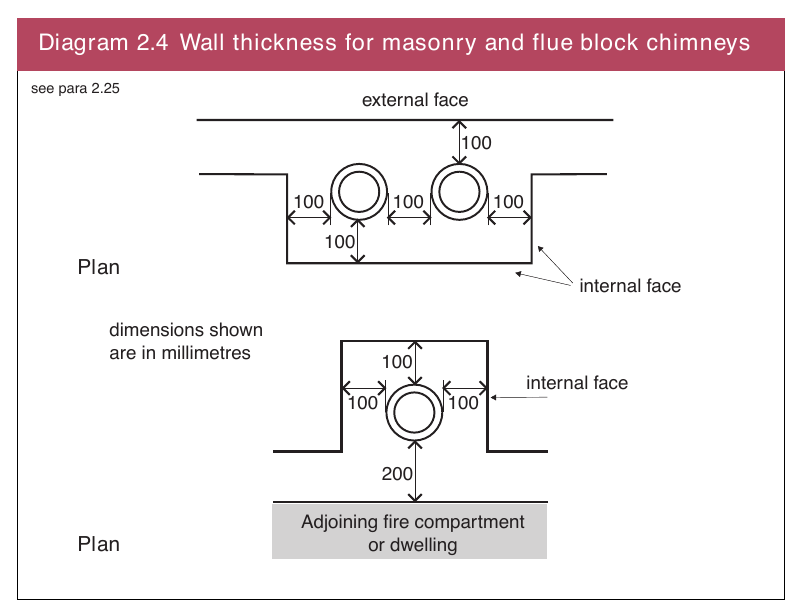
Diagram 2.4 Wall thickness for masonry and flue block chimneys
Spaces between the lining and the surrounding masonry should not be filled with ordinary mortar. In the absence of the liner manufacturer's instructions, the space should be filled with one of the following weak insulating concrete mixes –
(a)one part ordinary Portland cement to 20 parts suitable lightweight expanded clay aggregate, minimally wetted;
(b)one part ordinary Portland cement to 6 parts Vermiculite; or
(c)one part ordinary Portland cement to 10 parts Perlite.
Construction of flue block chimneys
2.23A flue block chimney should be constructed of factory-made components suitable for the intended application and installed in accordance with the manufacturer's instructions. The flue blocks should have a minimum performance that corresponds to the designation T400 N2 S D 3, as described in BS EN 1443, such as clay flue blocks of Class FB1 N2 as described in BS EN 1806.
2.24Joints should be sealed in accordance with the flue block manufacturer's instructions. Bends and offsets should only be formed with matching factory-made components.
Thickness of masonry and flue block chimneys
2.25The thickness of the walls for a masonry chimney around the flue, excluding the thickness of any flue liner, should be in accordance with Diagram 2.4.
Page 28
#Source page 28
Flue pipes
2.26A flue pipe should be constructed from –
(a)cast iron complying with BS 41;
(b)metal flue pipes appropriately designated in accordance with BS EN 1856: 2 to suit the appliance and types of fuels to be burnt (refer to detailed guidance in Sections 3, 4 and 5);
(c)vitreous enamelled steel pipe complying with BS 6999; or
(d)other flue pipes having the necessary performance designation for use with the intended appliance.
2.27A flue pipe with spigot and socket joints should be fitted with the socket facing upwards to contain moisture and other condensates in the flue. Joints should be made gas-tight by the use of proprietary jointing accessories or, where appropriate, by packing joints with non-combustible rope or fire cement.
2.28A plastic flue pipe should be appropriately designated in accordance with BS EN 14471 to suit the appliance, fuel and flue characteristics.
Repair or re-use of existing flues
2.29Where it is proposed to bring an existing flue back into use, or an existing flue is to be used with a different type or rating of combustion appliance, it should be cleaned, visually inspected and if necessary altered to ensure that it is suitable for the proposed use.
2.30A defective flue should be lined using the materials and components described in Sections 3, 4, and 5 dependent upon the type of combustion appliance proposed.
2.31The use of an oversized flue can be unsafe so a flue should be lined to reduce the flue area to suit the intended combustion appliance.
2.32If a chimney has been relined in the past using a metal lining system and the appliance is being replaced, the metal liner should also be replaced, unless it can be proven that it was recently installed and it can be seen to be in good condition.
Use of flexible metal flue liners for the relining of chimneys
2.33A chimney may be relined using a flexible metal flue liner, appropriately designated in accordance with BS EN 1856: 2 to suit the appliance, fuel and flue gas characteristics. Flexible flue liners should only be used to reline a chimney and should not be used as the primary liner of a new chimney. They can be used to connect gas back boilers to chimneys where the appliance is located in a fireplace recess.
Page 29
#Source page 29
Factory-made metal chimneys
2.34A factory-made metal chimney should be –
(a)a component system independently certified as complying with the relevant sections of BS EN 1856: 1 and installed in accordance with the relevant recommendations of BS EN 15287: 1; or
(b)a twin wall component system for an oil-fired appliance and a single wall component system for gas complying with the recommendations of BS EN 1856: 1 and for gas appliances, installed in accordance with the recommendations of BS 5440: Part 1, where the flue temperatures will not normally exceed 250ºC.
2.35Where a factory-made metal chimney passes through a wall, sleeves should be provided to prevent damage to the flue or building through thermal expansion. To facilitate the checking of gas-tightness, joints between chimney sections should not be concealed within ceiling joist spaces or within the thickness of walls unless proper access is provided.
2.36A factory-made metal chimney should be installed so that the appliance can be withdrawn without the need to dismantle the chimney.
2.37A factory-made metal chimney should be kept a safe distance away from any combustible material. For a chimney designated to BS EN 1856: 1 the following provisions are a reasonable method of achieving this –
(a)locate the chimney not less than the distance “XX” from the combustible material, where “XX” is the dimension defined in BS EN 1856: 1 as shown in Diagram 2.5; or
(b)where the chimney passes through a cupboard, storage space or roof space, a suitable guard should be provided no closer to the outer wall of the chimney than “XX” as given above. See Diagram 2.5.
In no circumstances should the separation “XX” between the chimney and the combustible material, or suitable guard be less than 25 mm.
Diagram 2.5 The separation of combustible material from a factory-made metal chimney, passing through a cupboard, storage space or roof space, designated to BS EN 1856: 1
#Source page 30
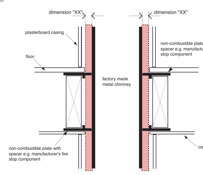
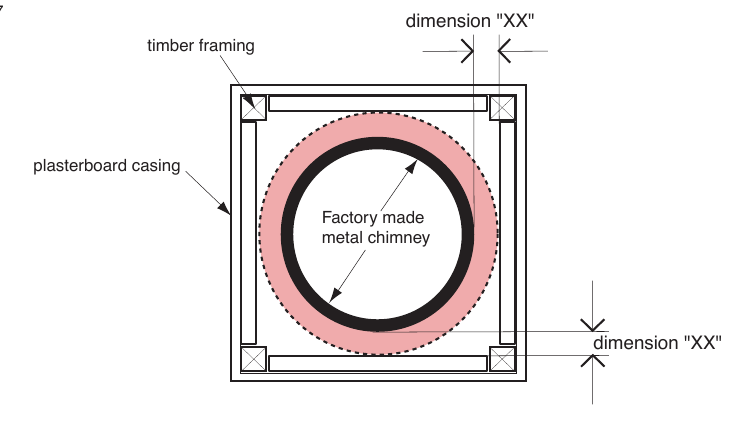
Diagram 2.5 The separation of combustible material from a factory-made metal chimney, passing through a cupboard, storage space or roof space, designated to BS EN 1856: 1
see para 2.37
Plan ceiling dimension "XX" non-combustible plate with stop component
Section
No combustible material in shaded zone. Width of shaded zone at least equal to manufacturer's declared minimum distance (XX mm) as defined by testing to BS EN 1443: 2003 or 25 mm, whichever is the greatest
Page 31
#Source page 31
2.38Where a factory-made metal chimney penetrates a fire compartment wall or floor the casing of the chimney should comply with the requirements of Part E of the Building Regulations.
Concealed flues
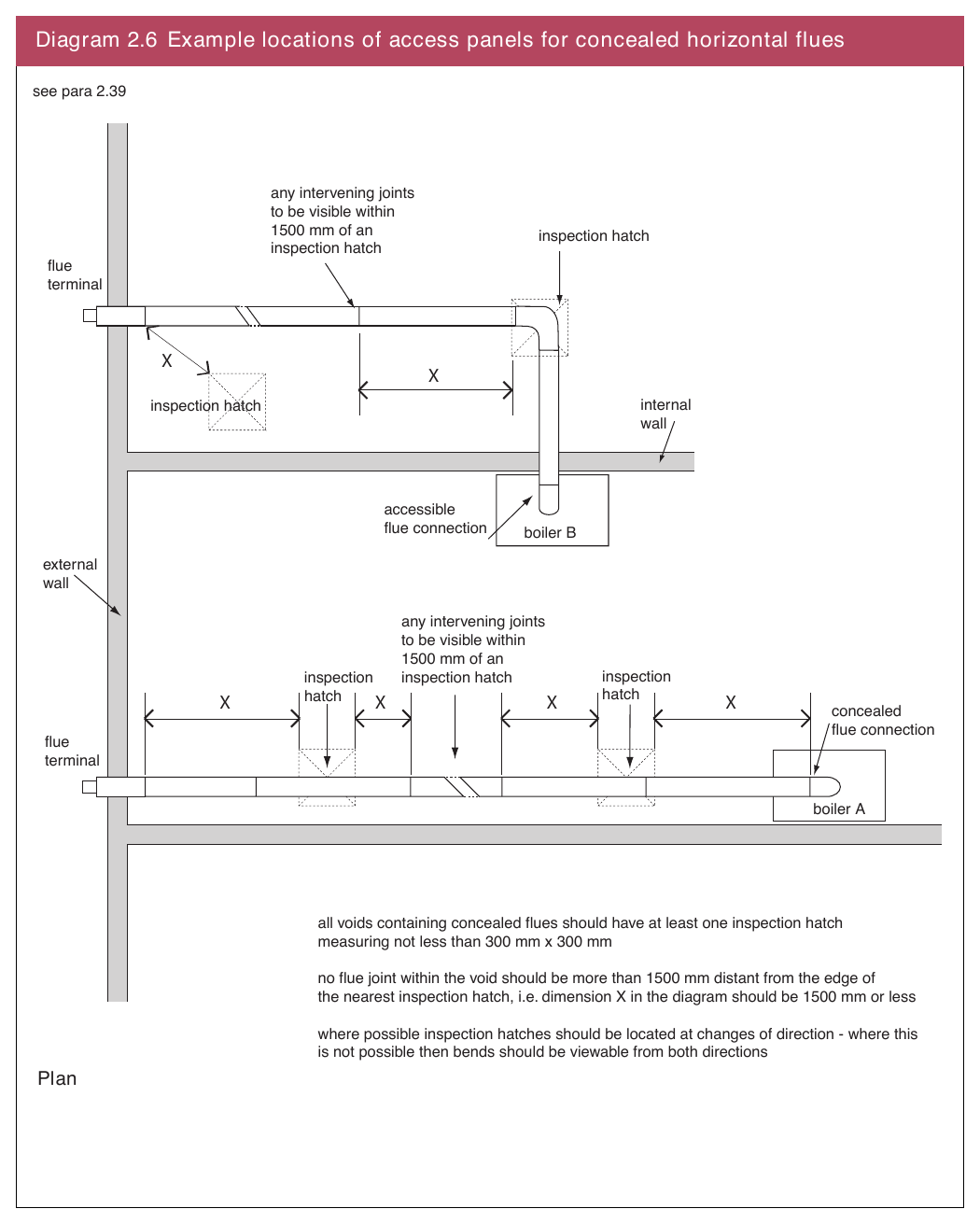
2.39Where a flue is routed within a void, appropriate means of access at strategic locations should be provided to allow the following aspects to be visually checked and confirmed –
(a)the flue is continuous throughout its length;
(b)all joints appear correctly assembled and are appropriately sealed;
(c)the flue is adequately supported throughout its length; and
(d)any required gradient of fall back to the boiler (required to recover the condensate produced as part of the combustion process) and any other required drain points have been provided.
This is necessary when an appliance is first installed and should subsequently assist when the appliance is maintained.
The means of access for flues needs to be sufficiently sized and positioned to allow a visual inspection of the flue to be undertaken, particularly at any joints in the flue. It is not intended that the means of access should be sized to allow full physical access to the flue system.
Flues should not pass through another premises since access for inspection may not always be available to that premises and chimney system running through it. Flues may pass through communal areas including purpose- designed ducts where inspection access is provided.
Any ‘means of access’ should not impair any fire, thermal or acoustic requirements of the Building Regulations. Where necessary, inspection panels or hatches should be fitted with resilient seals and provide the similar standards of fire, thermal and acoustic isolation to the surrounding structure.
Access hatches should be at least 300 mm x 300 mm or larger where necessary to allow sufficient access to the void to look along the length of the flue.
Diagram 2.6 shows examples of access panels for a horizontal flue in a ceiling void.
Page 32
#Source page 32
Diagram 2.6 Example locations of access panels for concealed horizontal flues
Page 33
#Source page 33
Diagram 2.7 Bends in flues
Configuration of natural draught flues serving open-flued appliances
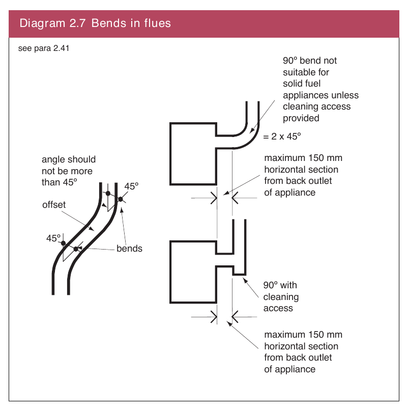
2.40A flue system should offer least resistance to the passage of the flue gas by minimising changes in direction or horizontal length. Where practicable the flue should be straight and vertical except for the connection to a combustion appliance with a rear outlet. The connecting horizontal section should be not greater than 150 mm in length and where bends are essential, they should be angled at not more than 45º to the vertical.
2.41Provisions should be made to enable the flue to be swept and inspected. The number of changes of direction between the combustion appliance outlet and the flue outlet should be limited to not more than four 45º bends with not more than two of these being between an intended point of access for sweeping and either another point of access for sweeping or the flue outlet. 90º factory-made bends, elbows or tee pieces in flue pipes should be treated as being equal to two 45º bends. See Diagram 2.7.
Openings in flues for inspection and cleaning
2.42A flue should not have an opening into more than one room or space except for the purposes of –
(a)inspection or cleaning; or
(b)fitting an explosion door, draught break, draught stabiliser or draught diverter.
Dry lining around fireplace openings
#Source page 34
2.43Openings for inspection and cleaning should be formed using purpose factory-made components that are compatible with the flue system. The access cover to the opening should have the same level of gas-tightness as the flue system and an equal level of thermal insulation.
2.44Openings for cleaning the flue should allow easy passage of the sweeping brush and be non-combustible except where fitted to a combustible flue pipe, such as a plastic flue pipe. It should be possible to sweep the whole flue after the appliance has been installed.
Dry lining around fireplace openings
2.45Where a decorative treatment, such as a fireplace surround, masonry cladding or dry lining, is provided around a fireplace opening, any gaps that could allow flue gas to escape from the fireplace opening into the void behind the decorative treatment should be sealed to prevent such leakage. The sealing material should be capable of remaining in place despite any relative movement between the decorative treatment and the fireplace recess.
Condition of combustion installations at completion
2.46A flue should be checked at completion to ensure that it is free from obstructions, satisfactorily gas-tight and constructed with materials and components of sizes that suit the intended application.
Where the building work includes the installation of a combustion appliance, all of the tests should include the flue pipe and the gas-tightness of the joint between the flue pipe and the combustion appliance outlet. A spillage test should be carried out with the appliance under fire.
Notice plates for hearths and flues
2.47To satisfy the requirements of Regulation 74 in Part L, a durable notice should be provided to convey –
(a)the location of the hearth, fireplace (or flue box) or the location of the beginning of the flue;
(b)the generic type(s) of combustion appliances that can be safely accommodated;
(c)the type and size of the flue (or its liner if it has been relined) and the manufacturer's name; and
(d)who installed the hearth, fireplace, flue or chimney and the date of installation.
2.48Notice plates should be robust, indelibly marked and securely fixed in an unobtrusive but obvious position within the building such as –
(a)next to the electricity consumer unit; or
(b)next to the chimney or hearth described.
Access to combustion appliances for maintenance
#Source page 35
Diagram 2.8 Notice plates for hearths and flues
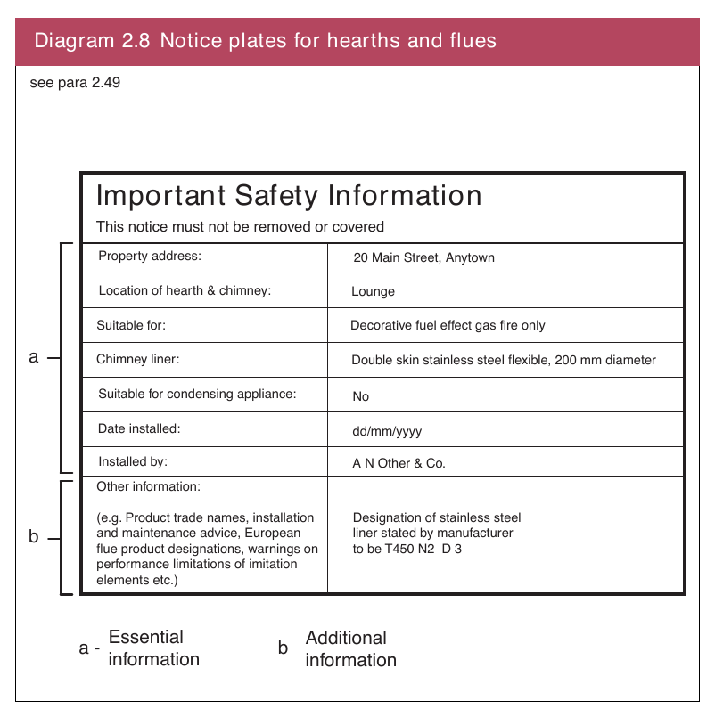
2.49For flue products whose performance characteristics have been assessed in accordance with a European Standard (EN) and which are supplied or marked with a designation as defined in Section 2, the installer should include this designation, under additional information, on the notice plate as shown in Diagram 2.8.
| Important Safety Information This notice must not be removed or covered | |
|---|---|
| Property address: | 20 Main Street, Anytown |
| Location of hearth & chimney: | Lounge |
| Suitable for: | Decorative fuel effect gas fire only |
| Chimney liner: | Double skin stainless steel flexible, 200 mm diameter |
| Suitable for condensing appliance: | No |
| Date installed: | dd/mm/yyyy |
| Installed by: | A N Other & Co. |
| Other information: (e.g. Product trade names, installation and maintenance advice, European flue product designations, warnings on performance limitations of imitation elements etc.) | Designation of stainless steel liner stated by manufacturer to be T450 N2 D 3 |
a - b -
Access to combustion appliances for maintenance
2.50 A permanent means of safe access should be provided to a combustion appliance for maintenance.
Detection and warning of the presence of carbon monoxide
#Source page 36
Carbon monoxide alarms
2.51Where a new or replacement combustion appliance, not designed solely for cooking purposes, is installed in a dwelling, a carbon monoxide detector/alarm should be provided in the room where the appliance is located. However, if the combustion appliance is installed in a room or space not normally used e.g. a boiler room/cupboard, the detector/alarm should be located just outside the room or space. This should allow the alarm to be heard more easily.
2.52Carbon monoxide alarms should comply with BS EN 50291 and be powered by a battery designed to operate for the working life of the alarm. The alarm should incorporate a warning device to alert users when the working life of the alarm is due to pass. Mains-powered BS EN 50291 Type A carbon monoxide alarms with fixed wiring (not plug-in types) may be used as alternative applications provided they are fitted with a sensor failure warning device.
2.53The carbon monoxide alarm should be located –
(a)on the ceiling at least 300 mm from any wall or, if it is located on a wall, as high up as possible (and above the height of any doors or windows) but not within 150 mm of the ceiling; and
(b)between 1000 mm and 3000 mm horizontally from the appliance.
Further guidance on the installation of carbon monoxide alarms is available in BS EN 50292 and from manufacturers’ instructions.
Air supply to appliances
#Source page 37
Section 3 Solid fuel burning appliances (including solid biofuel) with a rated heat output up to 50 kW
This section sets out the additional guidance and provisions that should be met for a solid fuel burning combustion appliance over and above those provisions given in Section 2.
Air supply to appliances
3.1Any room or space containing a combustion appliance should have a permanent air vent opening of a size not less than that shown in Table 3.1. For an appliance designed to burn a range of different solid fuels, the air supply should be designed to accommodate burning the fuel that produces the highest heating output.
3.2Where the manufacturer’s installation instructions require greater areas of permanently open air vents than those specified in Table 3.1, the manufacturer’s advice should be followed.
Flues and chimneys
#Source page 38
| Table 3.1 Air supply to solid fuel burning appliances | ||||
|---|---|---|---|---|
| Type of appliance | Type and amount of ventilation(1) | |||
| Open appliance such as an open fire with no throat, e.g. a fire under a canopy as in Diagram 3.6 | Permanently open air vent(s) with a total equivalent area of not less than 50% of the cross- sectional area of the flue | |||
| Open appliance, such as an open fire with a throat as in Diagram 3.5 and 3.12 | Permanently open air vent(s) with a total equivalent area of not less than 50% of the throat opening area(2) | |||
| Other appliance, such as a stove, cooker or boiler, with a flue draught stabiliser | Permanently open vents as below: If design air permeability >5.0 m³/(h.m²) then - 300 mm²/kW for first 5 kW of appliance rated output; and 850 mm²/kW for balance of appliance rated output. If design air permeability ≤5.0 m³/(h.m²) then - 850 mm²/kW of appliance rated output(3) | |||
| Other appliance, such as a stove, cooker or boiler, with no flue draught stabiliser | Permanently open vents as below: If design air permeability >5.0 m³/(h.m²) then - 550 mm²/kW of appliance rated output above 5 kW If design air permeability ≤5.0 m³/(h.m²) then - 550 mm² per kW of appliance rated output(3) | |||
| Notes: (1) Extract fans should not be installed in the same room or space as a solid fuel burning appliance, see paragraph 2.17. (2) For simple open fires as depicted in Diagram 3.12 the air supply requirement can be met with room ventilation areas as follows - | ||||
| Nominal fireplace opening size | 500 mm | 450 mm | 400 mm | 350 mm |
| Total equivalent area of permanently open air vents | 20500 mm² | 18500 mm² | 16500 mm² | 14500 mm² |
| (3) A dwelling constructed prior to 2008 should not normally have an air permeability of less than 5.0 m³/(h.m²) at 50 Pa unless extensive measures have been taken to improve air tightness, see Appendix C. When it is not possible to determine if the air permeability of a dwelling is likely to be more than 5.0 m³/(h.m²) then it should be assumed that the dwelling has an air permeability of 5.0 m ³/(h.m²) or less. 4 Example: an appliance with a flue draught stabiliser and a rated heat output of 7 kW would require a permanently open air vent with a equivalent area of – (5 x 300) + (2 x 850) = 3200 mm². 5 Equivalent area is measured according to the method in BS EN 13141: 1 or estimated according to paragraph 2.10. Divide the area given in mm² by 100 to find the corresponding area in cm². |
Flues and chimneys
Size of flues
3.3A flue should be sized to suit the intended appliance to ensure an adequate discharge velocity of the flue gas that will prevent flow reversal problems but will not impose excessive flow resistance.
3.4A flue pipe should have the same diameter or equivalent cross-sectional area as that of the appliance flue outlet and should be not smaller than the size recommended by the appliance manufacturer.
Page 39
#Source page 39
Diagram 3.1 Examples of large or unusual fireplace openings
3.5A flue should be not less than the size shown in Table 3.2 that is relevant to the particular appliance, and not less than the size of the appliance flue outlet or that recommended by the appliance manufacturer.
3.6For a multifuel appliance, the flue should be sized to accommodate burning the fuel that generates the greatest rated heat output.
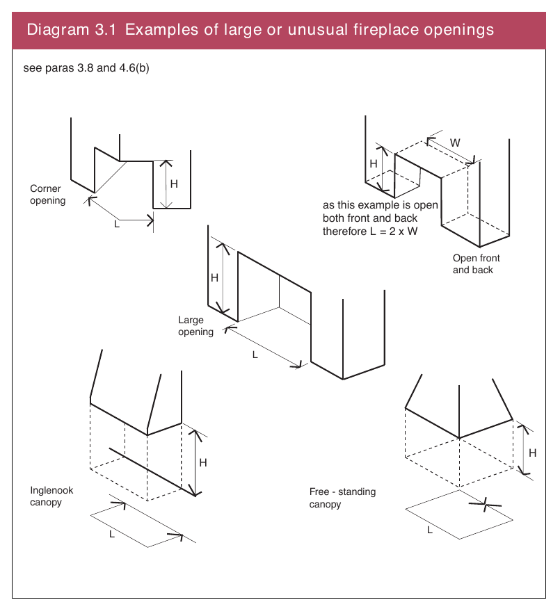
3.7A fireplace with an opening greater than 500 mm x 550 mm or a fireplace exposed on two or more sides, such as a fireplace under a canopy or open on both sides of a central chimney breast, should have a flue with a cross- sectional area equal to 15% of the total face area of the fireplace opening(s).
3.8The opening area of a fireplace should be calculated using the following formula –
Face area Total horizontal length of Height of fireplace
= X
(mm2) fireplace opening L (mm) opening H (mm)
Examples of L and H for large or unusual fireplace openings are shown in Diagram 3.1.
Height of flues
#Source page 40
| Table 3.2 Sizes of flues for chimneys | |
|---|---|
| Installation(1) | Minimum flue size |
| Fireplace with an opening of up to 500 mm x 550 mm. | 200 mm diameter or a rectangular/square section having the equivalent cross-sectional area and a minimum side dimension of 175 mm. |
| Fireplace with an opening greater than 500 mm x 550 mm or a fireplace exposed on two or more sides. | See paragraph 3.7. If a rectangular/square section flue is used the minimum side dimension should be not less than 200 mm. |
| Closed appliance with a rated heat output not greater than 20 kW which – (a) burns smokeless or low volatiles fuel(2); (b) is an appliance which meets the requirements of the Clean Air (Northern Ireland) Order when burning an appropriate bituminous coal(3); or (c) is an appliance which meets the requirements of the Clean Air (Northern Ireland) Order when burning wood(3). | 125 mm diameter or rectangular/square section having the equivalent cross-sectional area and a minimum side dimension of 100 mm. |
| Pellet burner or pellet boiler which meets the requirements of the Clean Air (Northern Ireland) Order(3). | 125 mm diameter This may be reduced to no less than 100 mm when permitted by the appliance manufacturer and supported by calculation according to BS EN 13384: 1. This calculation can be applied to an individual installation or manufacturers can provide precalculated designs. |
| Other closed appliances with a rated heat output not greater than 30 kW burning any fuel. | 150 mm diameter or rectangular/square section having the equivalent cross-sectional area and a minimum side dimension of 125 mm. |
| Closed appliances with a rated heat output greater than 30 kW but not exceeding 50 kW burning any fuel. | 175 mm diameter or rectangular/square section having the equivalent cross-sectional area and a minimum side dimension of 150 mm. |
| Notes: (1) Closed appliance includes cookers, stoves, room heaters and boilers. (2) Fuels such as bituminous coal, untreated wood or compressed paper are not smokeless or low volatiles fuel. (3) These appliances are known as ‘exempted fireplaces’. 4. Should an offset be necessary in a flue, each flue size dimension should be increased by 25 mm (i.e. diameter or side). |
Height of flues
3.9A flue should be high enough to ensure a sufficient draught to clear the products of combustion. The height necessary for this depends upon the type of appliance, the height of the building, the type of flue and the number of bends in it, and a careful assessment of local wind patterns. A flue should be satisfactory if –
(a)it is at least 4.5 m in height and the provisions of paragraphs 3.11 to
3.13are adopted; or
(b)the calculation procedure within BS EN 13384: 1 is used as the basis for deciding whether a flue design should provide sufficient draught.
Outlets from flues
#Source page 41
3.10The height of a flue serving an open fire is measured vertically from the highest point at which air can enter the fireplace to the level at which the flue discharges into the outside air. The highest point of air entry into the fireplace should be the top of the fireplace opening or, for a fire under a canopy, the bottom of the canopy. The height of a flue serving a closed appliance is measured vertically from the appliance outlet.
Outlets from flues
3.11The outlet from a flue should be above the roof of the building in a position where the products of combustion can discharge freely and will not present a fire hazard, whatever the wind conditions.
3.12The flue outlet position, in common circumstances, should be in accordance with Table 3.3. However, the flue outlet position and/or separations shown in Table 3.3 may have to be increased, in particular cases, where the wind exposure, surrounding tall buildings, high trees or high ground have an adverse effect on the flue draught.
| Table 3.3 Flue outlet positions for solid fuel appliances | ||
|---|---|---|
| Item | Point where flue passes through weather surface(1)(2) | Clearance to flue outlet |
| 1 | At or within 600 mm of the ridge | Not less than 600 mm above the ridge. |
| 2 | Elsewhere on a roof, whether pitched or flat | Not less than 2300 mm horizontally from the nearest point on the weather surface; and (a) not less than 1000 mm above the highest point of intersection of the flue/chimney and the weather surface; or (b) not less than as high as the ridge. |
| 3 | Below (on a pitched roof) or within 2300 mm horizontally to an openable rooflight, dormer window or other opening (3) | Not less than 1000 mm above the top of the opening. |
| 4 | Within 2300 mm of an adjoining building, whether of not beyond the boundary(3) | Not less than 600 mm above the adjacent building. |
| Notes: (1) The weather surface is the building external surface, such as its roof, tiles or external walls. (2) A flat roof has a pitch less than 10º. (3) The clearances given for items 1 and 2, as appropriate, should also apply. 4. A vertical flue fixed to an outside wall should be treated as equivalent to an inside flue emerging at the nearest edge of the roof. |
Page 42
#Source page 42
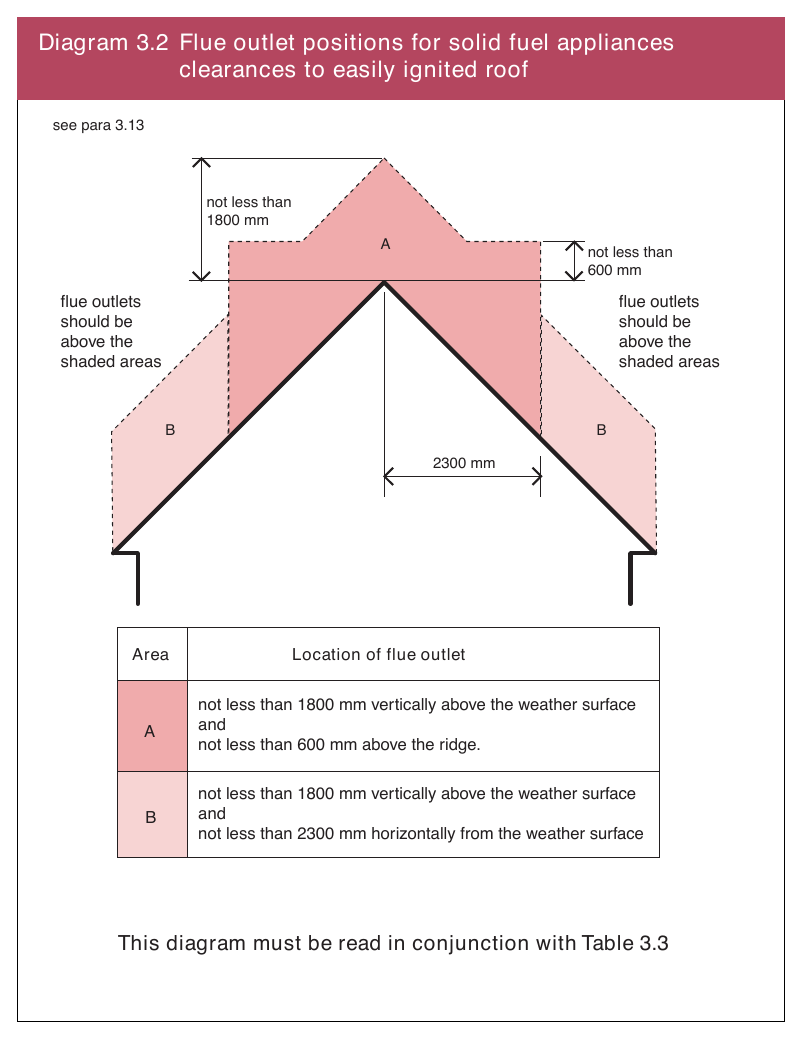
3.13Where a flue discharges onto, or in close proximity to, a roof with a surface that is readily ignitable, such as thatch or shingles, the clearances to the flue outlet should be increased to that shown in Diagram 3.2.
It should be noted that thatched roofs can sometimes be vulnerable to spontaneous combustion caused by heat transferred from flues building up in thick layers of thatch in contact with the chimney. To reduce this risk it is recommended that rigid twin-walled insulated metal flue liners be used within a ventilated (top and bottom) masonry chimney void provided they are adequately supported and not in direct contact with the masonry. Non-metallic chimneys and cast in-situ flue liners can also be used provided the heat transfer to the thatch is assessed in relation to the depth of thatch and risk of spontaneous combustion.
Diagram 3.2 Flue outlet positions for solid fuel appliances clearances to easily ignited roof
Location and shielding of flue pipes
#Source page 43
3.14A flue pipe should only be used to connect an appliance to its flue. It should not pass through any roof space, partition, internal wall or floor, except to pass directly into a flue through either a wall of the chimney or a floor supporting the chimney. A flue pipe should also be guarded if it could be at risk of damage or if the burn hazard it presents to people is not immediately apparent.
3.15 A flue pipe should be located so that it cannot ignite any combustible material. To ensure this –
(a)follow the guidance in paragraph 2.37 where the connecting flue pipe is a factory-made metal chimney whose performance is at least equal to designation T400 N2 D3 G according to BS EN 1856: 1 or BS EN 1856: 2, and installed to BS EN 15287: 1; or
(b)provide separation by shielding in accordance with Diagram 3.3.
Diagram 3.3 Protecting combustible material from uninsulated flue pipes for solid fuel appliances
see para 3.15 at least 3 x D
D at least at least
D 3 x D 1.5 x D flue pipe at least
1.5x D fluepipe at least
1.5x D at least
1.5x D air space of at least 12 mm between at least non-combustible shield and combustible 1.5 x D
| material | |||
|---|---|---|---|
| Elevation | Elevation | Plan without | Plan with |
| without shield | with shield | shield | shield |
shields should either:
a)extend beyond the flue pipe by at least 1.5 x D; or
b)make any path between flue pipes and combustible material at least 3 x D long
Page 44
#Source page 44
Debris collection space
3.16Where a flue cannot be cleaned through the appliance, a debris collecting space that is accessible for emptying and suitably sized opening(s) for cleaning should be provided at appropriate locations in the flue.
Masonry and flue block chimneys
3.17Masonry chimneys should be built in accordance with paragraphs 2.21 and
2.22.Flue block chimneys should be built in accordance with paragraphs 2.23 and 2.24. The minimum chimney thickness and distance to combustibles (xx mm) should be no less than the manufacturer’s product declaration (Gxx) based on testing to BS EN 1858 (concrete flue blocks) or BS EN 1806 (clay/ceramic flue blocks). Other masonry chimney products should exceed the minimum thickness indicated in Diagram 2.4.
Separation of combustible material from fireplaces and flues
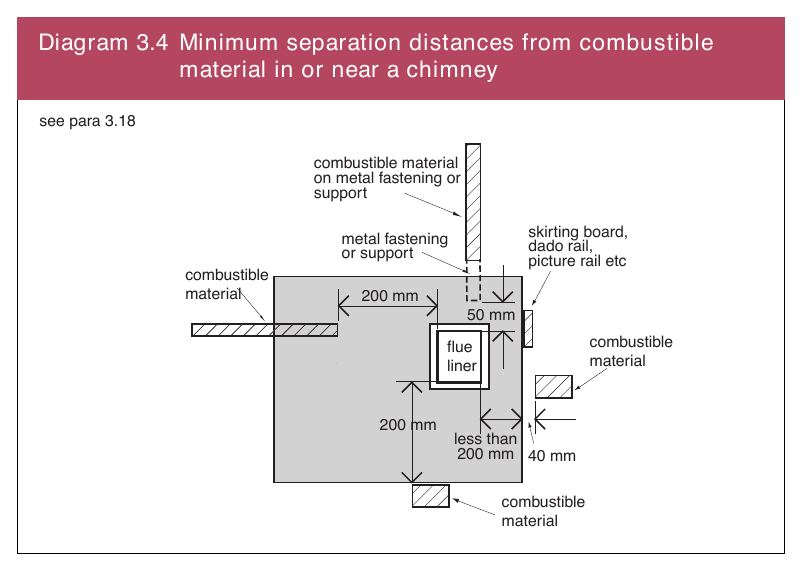
3.18Combustible material should not be located where the heat dissipating through the walls of a fireplace or flue could ignite it. The minimum separation distances for combustible material should be –
(a)200 mm from the inside surface of a flue or fireplace recess;
(b)at least xx mm from a flue product with designated separation distance (Gxx); or
(c)40 mm from the outer surface of a masonry chimney or fireplace recess unless it is a floorboard, skirting board, dado rail, picture rail, mantel shelf or architrave. Metal fixings in contact with combustible materials should be not less than 50 mm from the inside surface of a flue.
See Diagram 3.4.
Diagram 3. 4 Minimum separation distances from combustible material in or near a chimney
Page 45
#Source page 45
Factory-made metal chimneys
3.19Guidance on factory-made metal chimneys is given in paragraphs 2.34(a) and 2.35 to 2.38. Table 3.4 gives minimum performance designations for chimney and flue pipe components for use with new solid fuel fired appliances.
| Table 3.4 Minimum performance designations for chimney and flue pipe components for use with new solid fuel fired appliances | ||
|---|---|---|
| Appliance type | Minimum designation | Fuel type |
| All solid fuel appliance | Masonry or flue block flue with liner to T400 N2 D3 Gxx | Coal, smokeless fuel, peat, wood and other biomass |
| Clay flue blocks FB1N2 | ||
| Clay/ceramic liners B1N2 | ||
| Concrete liners B2 | ||
| factory-made metal chimneys to T400 N2 D3 Gxx | ||
| See paragraph 2.21 to 2.24 and 2.34(a) |
Lining or relining flues in chimneys
3.20The lining of a flue should correspond to the designation T400 N2 D3 G, as described in BS EN 1443.
Formation of gathers
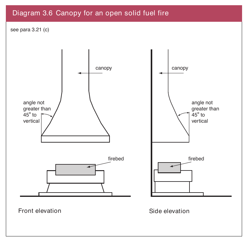
3.21To minimise resistance to the proper working of a flue, a tapered gather should be provided in the fireplace for an open fire. This should be formed by –
(a)using prefabricated gather components built into a fireplace recess as shown in Diagram 3.5(a);
(b)the corbelled masonry as shown in Diagram 3.5(b); or
(c)using a suitable canopy, as shown in Diagram 3.6.
Page 46
#Source page 46
Diagram 3.5 Construction of gathers
Hearths
#Source page 47
Diagram 3.6 Canopy for an open solid fuel fire
Hearths
3.22A hearth should be constructed of suitably robust materials and to appropriate dimensions so that, in normal use, it prevents the combustion appliance setting fire to the building fabric and furnishings.
If the chimney is not independently supported, the hearth should be able to accommodate the weight of the combustion appliance and its chimney.
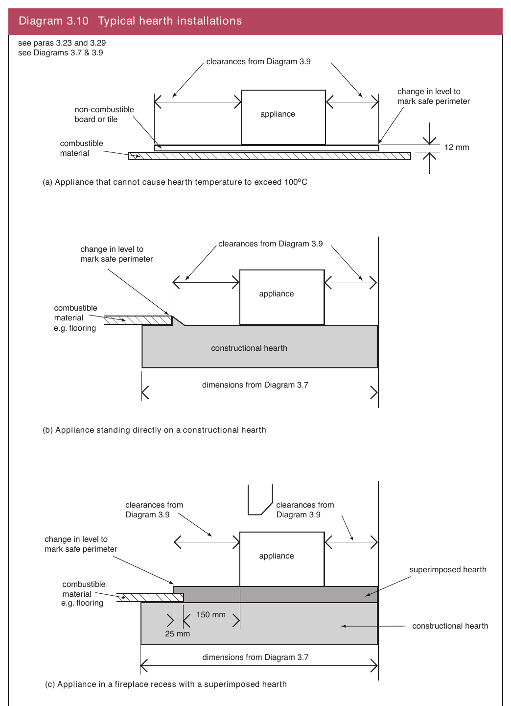
3.23Where an appliance is not to be located in an appliance recess and it has been independently certified that it cannot cause the temperature of the hearth to exceed 100ºC, it should stand wholly on a hearth made of non- combustible board, sheet material or tiles not less than 12 mm thick. See Diagram 3.10(a).
All other appliances should be placed on a constructional hearth in accordance with paragraphs 3.24 to 3.29. See Diagram 3.10(b) and (c).
Constructional hearths
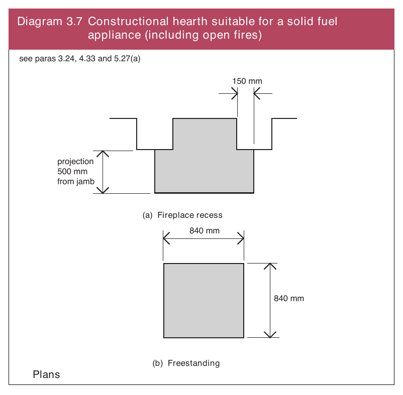
3.24A constructional hearth should –
(a)have plan dimensions not less than those shown in Diagram 3.7; and
(b)be made of solid, non-combustible material, such as concrete or masonry, not less than 125 mm thick, including the thickness of any non-combustible floor and/or decorative surface.
Page 48
#Source page 48
Diagram 3.7 Constructional hearth suitable for a solid fuel
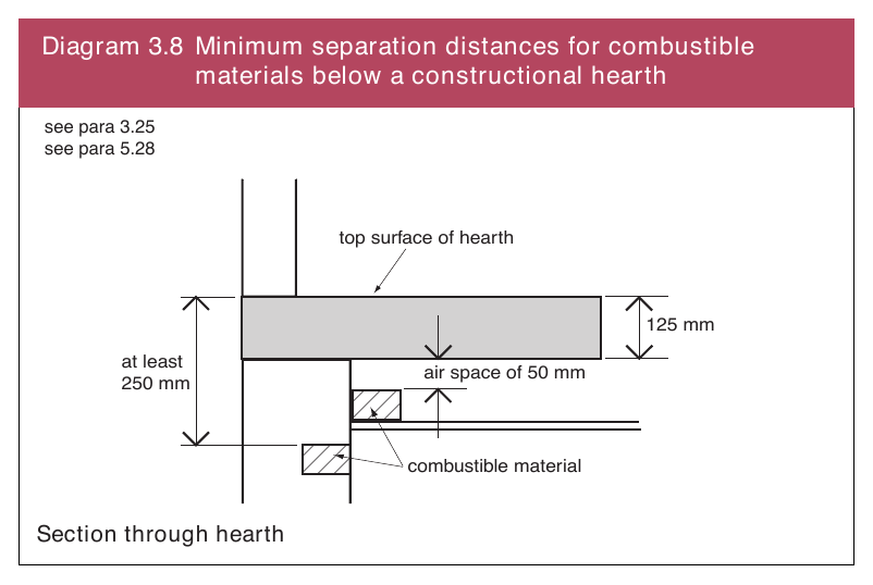
3.25Combustible material should not be placed beneath a constructional hearth unless –
(a)there is an air-space of not less than 50 mm between the underside of the hearth and the combustible material; or
(b)the combustible material is not less than 250 mm below the top of the hearth. See Diagram 3.8.
Diagram 3.8 Minimum separation distances for combustible materials below a constructional hearth
Page 49
#Source page 49
Diagram 3.9 Non-combustible hearth surface surrounding a solid
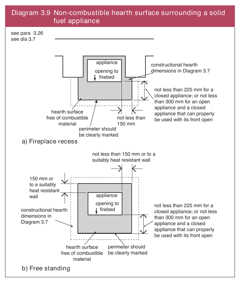
3.26An appliance should be located on a hearth so that it is surrounded by a surface free of combustible material as shown in Diagram 3.9. This surface may be part of the surface of the constructional hearth or it may be the surface of a superimposed hearth laid wholly or partly upon a constructional hearth. The edges of this surface should be marked with a change in level to provide a warning to the building occupants and to discourage combustible floor finishes such as carpet from being laid too close to the appliance.
not less than 225 mm for a closed appliance; or not less than 300 mm for an open appliance and a closed appliance that can properly be used with its front open
3.27The dimensions shown in Diagram 3.9 may be reduced to manufacturer’s recommendations for appliances with surface temperatures not exceeding 85ºC when in normal operation and where there is no risk of spillage of fuel or ash.
3.28Combustible material placed on or beside a constructional hearth should not extend under a superimposed hearth by more than 25 mm or closer than 150 mm, measured horizontally, to the appliance. See Diagram 3.10(c).
3.29Hearths should be installed as shown in Diagram 3.10(b) and (c).
Page 50
#Source page 50
Diagram 3.10 Typical hearth installations
Fireplace recesses and prefabricated appliance chambers
#Source page 51
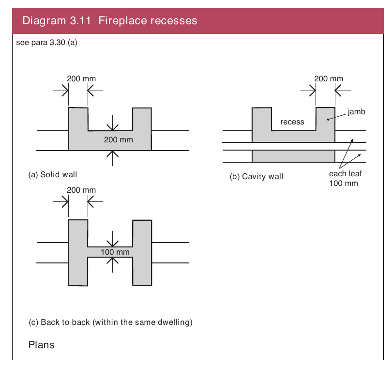
Diagram 3.11 Fireplace recesses
Fireplace recesses and prefabricated appliance chambers
3.30Fireplaces should be designed and constructed so that they adequately protect the building fabric from catching fire. They should be built utilising –
(a)a fireplace recess of masonry or concrete as shown in Diagram 3.11; or
(b)a prefabricated factory-made appliance chamber using components that are made of insulating concrete having a density of greater than 1200 kg/m3 but less than 1700 kg/m3 and a minimum thickness as shown in Table 3.5. Components should be supplied as a set for assembly and jointing in accordance with the manufacturer's instructions.
| Table 3.5 Minimum thickness of components for prefabricated appliance chambers | |
|---|---|
| Component | Minimum thickness (mm) |
| Base | 50 |
| Side section, forming wall on either side of chamber | 75 |
| Back section, forming rear chamber | 100 |
| Top slab, lintel or gather, forming top of chamber | 100 |
Page 52
#Source page 52
Diagram 3.12 Open fireplaces: throat and fireplace
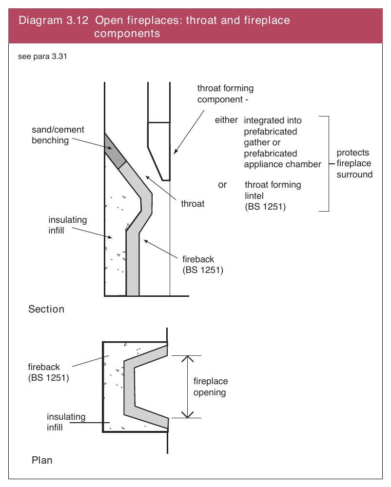
Fireplace lining components
3.31A fireplace recess should be protected from the heat of the combustion appliance by suitable fireplace lining components as shown in Diagram 3.12, or by lining the recess with suitable firebricks.
Walls adjacent to hearths
3.32Walls that are not part of a fireplace recess or a prefabricated appliance chamber, but are adjacent to a hearth or appliance, should protect the building from catching fire. They should be constructed in accordance with the provisions given in Diagram 3.13 and Table 3.6. Clearances shown in Diagram 3.13 may be reduced to manufacturer’s recommendations for appliances with surface temperatures not exceeding 85ºC when in normal operation.
Page 53
#Source page 53
Diagram 3.13 Walls adjacent to hearths

| Table 3.6 Dimensions of solid non-combustible walls adjacent to hearths | ||
|---|---|---|
| Location of hearth or appliance | Solid non-combustible material | |
| Thickness (T) | Height (H) | |
| where the hearth abuts a wall and the appliance is not more than 50 mm from the wall | 200 mm | not less than 300 mm above the appliance and not less than 1200 mm above the hearth |
| where the hearth abuts a wall and the appliance is more than 50 mm but not more than 300 mm from the wall | 75 mm | not less than 300 mm above the appliance and not less than 1200 mm above the hearth |
| where the hearth does not abut a wall and is not more than 150 mm from the wall (see note below) | 75 mm | not less than 1200 mm above the hearth |
| Note: 1. There is no requirement for protection of the wall where X in Diagram 3.13 is more than 150 mm. |
Gas burning appliances
#Source page 54
Section 4 Gas burning appliances with a rated heat input up to 70 kW (net)
This section sets out the additional provisions that should be met for gas burning appliances over and above those given in Section 2.
Gas burning appliances
Gas fires (other than flueless gas fires)
4.1Diagram 4.1 shows the three main types of gas-fired combustion appliances in this category, the building provisions for accommodating them safely differ for each type.
4.2A gas fire should be installed in a fireplace that has –
(a)a flue designed specifically for a gas appliance; or
(b)a flue designed to serve a solid fuel appliance, provided it can be shown to be safe.
The Gas Appliances (Safety) Regulations 1995 (Statutory Instrument 1995 No. 1629) require that particular combinations of appliance, flue box (where required) and flue must be selected from those stated in the manufacturer's instructions as having been shown to be safe by a Notified Body.
Flueless instantaneous water heaters
4.3A flueless instantaneous water heater should not be installed in a room or space having a volume of less than 5 m3.
Appliances fitted in bedrooms, bathrooms and shower rooms
4.4An open-flued gas-fired appliance should not be installed in a bedroom, bathroom or shower room, as there is an increased risk of carbon monoxide poisoning. If a combustion appliance must be installed in such a room then a room-sealed appliance should be provided.
Page 55
#Source page 55
Diagram 4.1 Types of gas fire
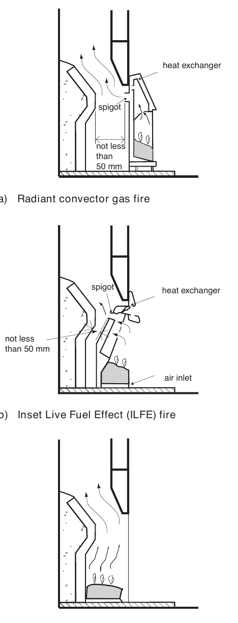
see para 4.1 & 4.32
Radiant convector gas fires, convector heaters and fire / back boilers, as described in BS 5871: Part 1
These stand in front of a closure plate which is fitted to the fireplace opening of a fireplace recess or suitable fluebox. The appliance covers the full height of the fireplace opening so that air only enters through purpose designed openings and the flue gases only discharge through the flue spigot.
Inset Live Fuel Effect (ILFE) fires, as described in BS 5871: Part 2
These stand fully or partially within a fireplace recess or suitable fluebox and give the impression of an open fire. The appliance covers the full height of the fireplace opening so that air only enters through purpose designed openings and the flue gases only discharge through the spigot.
Decorative Fuel Effect (DFE) fires, as described in BS 5871: Part 3
These are gas-fired imitations which can be substituted for the solid fuel appliances in open fires. Where suitable, they can also be used in flueboxes designed for gas appliances only.
Common designs include beds of artificial coals shaped to fit into a fireplace recess or baskets of artificial logs for use in larger fireplaces or under canopies.
(c) Decorative Fuel Effect (DFE) fire
Note: For illustration purposes, this diagram shows gas fires installed at or within a fireplace recess formed by fireplace components within a builder's opening. The actual setting for an appliance depends upon its type and manufacturer’s installation instructions.
Air supply and ventilation
#Source page 56
Air supply for flued Decorative Fuel Effect (DFE) fires
4.5A permanently open air vent should not be necessary for a DFE fire provided –
(a)the dwelling in which it is to be installed has an air permeability greater than 5.0 m3/hr/m2. See Appendix C;
(b)the appliance has a rated heat input not greater than 7 kW (net); and
(c)there is a flue gas clearance rate (without spilling) not greater than 70 m3/hour.
4.6Where the provisions of paragraph 4.5 do not apply, any room or space intended to contain any other DFE fire should have a permanently open air vent as follows –
(a)for a DFE fire in a fireplace recess with a throat, the air vent equivalent area should be not less than 10000 mm2; or
(b)for a DFE fire in a fireplace with no throat, such as a fire under a canopy, the air vent free area should be sized in accordance with the provisions in Section 3, Table 3.1, as if the room were intended to contain a solid fuel fire.
Air supply for flued appliances other than Decorative Fuel Effect (DFE) Fires
4.7This type of combustion appliance includes Inset Live Fuel Effect (ILFE) fires, radiant convector fires and boilers, in both room-sealed and open-flued variants.
4.8The size of the free air supply to the combustion appliance should be in accordance with the provisions shown in Diagram 4.2.
Example of calculation of free area of air vent using Diagram 4.2
4.9An open-flued boiler with a rated input of 15 kW (net) is installed in an appliance compartment such as a boiler room, which is ventilated directly to the outside. The design of the boiler is such that it requires cooling air. In these circumstances –
The cooling air is exhausted via vent D, which has an area of –
15x 500 = 7500 mm2
The cooling air and the air needed for combustion and the safe operation of the flue enters via vent E, which has an area of –
15x 1000 = 15000 mm2
Page 57
#Source page 57
Diagram 4.2 Free areas of permanently open air vents for gas appliance installations (other than decorative fuel effect fires or flueless appliances)
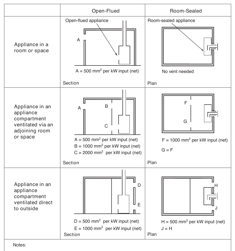
see para 1.2, 4.8 & 4.9 vents at B, D, F and H are high level vents
1.A, D, E, H and J are permanently open vents to the outside. B, C, F and G are permanently open vents between an appliance compartment and a room or space.
2.Calculations employ the appliance rated net heat input.
3.The area given above is the free area of the vent(s) or the equivalent free area for ventilators of more complex design.
4.Vents at C, E, G, and J are low level vents, Vents B, D, F and H are high level vents.
5.In older dwellings with an air permeability which is more than 5.0 m³/h/m² the first 7kW (net) can be ignored.
Flueless appliances
#Source page 58
4.10The ventilation for a flueless gas appliance should be provided in accordance with Table 4.1. For some flueless appliances, it may be necessary to provide permanently open air vents and/or make provision for rapid ventilation as recommended in BS 5440: 2.
4.11A room containing a gas point intended for use with a flueless appliance (such as a cooker, or space heater or water heater, with the gas point not adjacent to a flue) should have the ventilation provision calculated on the basis that an appliance with the largest rating consistent with Table 4.1 could be installed there.
| Table 4.1 Ventilation for flueless gas appliances | |||
|---|---|---|---|
| Flueless appliance type | Maximum appliance rated heat input | Volume of room, space or internal space (m ³)(1) | Free area of permanently open air vent (mm²)(2) |
| Cooker, oven hotplate or grill or combination thereof | Not applicable | < 5 | 10000 |
| 5 to 10 | 5000(3) | ||
| > 10 | no permanently open vent needed | ||
| Instantaneous water heater | 11 kW (net) | < 5 | Installation of water heater not permitted |
| 5 to 10 | 10000 | ||
| > 10 to 20 | 5000 | ||
| > 20 | no permanently open vent needed | ||
| Space heater not in an internal space(1)(2) | 0.045 kW (net) per m³ volume of room or space(4) | All cases | 10000 PLUS 5500 per kW input (net) in excess of 2.7 kW (net) |
| Space heater in an internal space(1)(2) | 0.090 kW (net) per m³ volume of internal space | All cases | 10000 PLUS 2750 per kW input (net) in excess of 5.4 kW (net) |
| Notes: (1) An internal space means one which communicates with several rooms or spaces, such as a hallway or landing. (2) For LPG fired space heaters conforming to BS EN 449: 2002+A1 the recommendations of BS 5440: 2 should be followed. (3) No permanent opening required if the room has a door that opens directly to outside. (4) No permanent open air vent is required if the room or space has a door which opens directly to the outside. 5. The permanent ventilation provisions listed in this table are additional to the openable elements or (for kitchens only) extract ventilation in accordance with Part K. Examples: a. Space heater in a lounge measuring 4 m x 4 m x 2.4 m = 38.4 m³, the appliance rated input should be not greater than 38.4 x 0.045 = 1.73 kW. b. Space heater in a hallway with a rated input of 7 kW (net) should have a permanently open air vent with a free area of 10000 + 2750 x (7 - 5.4) = 14400 mm². |
Flues and chimneys
#Source page 59
Size of natural draught flues for open-flued appliances
4.12A flue should be sized in accordance with Table 4.2 to suit the intended appliance and to ensure an adequate discharge velocity to prevent flow reversal problems but not to impose excessive flow resistance.
4.13For an appliance that is CE marked as compliant with the Gas Appliances (Safety) Regulations 1995, the flue should be sized in accordance with the manufacturer's installation instructions.
4.14The flue pipe should be the same size as the appliance flue outlet and the flue should have at least the same cross-sectional area as that of the appliance flue outlet.
| Table 4.2 Size of flues for gas-fired appliances | |
|---|---|
| Intended installation | Minimum flue size |
| Radiant/convector gas fire (new flue) | Circular - 125 mm diameter Rectangular - 16500 mm² cross-sectional area with a minimum side dimension of 90 mm |
| Radiant/convector gas fire (existing flue) | Circular - 125 mm diameter Rectangular - 12000 mm² cross-sectional area with a minimum side dimension of 63 mm |
| ILFE fire or DFE fire within a fireplace opening up to 500 mm x 550 mm | Circular or rectangular - Minimum flue dimension of 175 mm(1) (diameter and side) |
| DFE fire installed in a fireplace opening in excess of 500 mm x 550 mm | Calculate in accordance with Section 3, paragraph 3.7 to 3.8. |
| Note: (1) Some ILFE and DFE appliances are suitable for use with a circular flue with a diameter not less than 125 mm or a rectangular flue with a cross-sectional area of not less than 16500 mm² with a minimum side dimension of 90 mm. |
Height of natural draught flues for open-flued appliances
4.15A flue should be high enough to ensure sufficient draught to safely clear the products of combustion. For an appliance that is CE marked as compliant with the Gas Appliances (Safety) Regulations 1995, it should be installed in accordance with the manufacturer's installation instructions.
4.16Where an older appliance that is not CE marked is to be used and it has no manufacturer’s installation instructions it should be installed in accordance with –
(a)the recommendations in BS 5871: Part 3 for decorative fuel effect (DFE) fires; or
(b)the recommended calculation procedures in BS 5440: Part 1 for appliances other than decorative fuel effect fires.
Page 60
#Source page 60
Diagram 4.3 Location of outlets from flues serving gas appliances
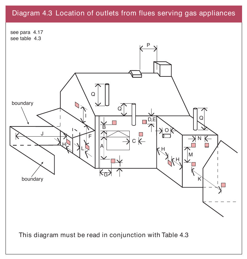
Outlets from flues
4.17The outlet from a flue should be so situated externally as to allow the safe dispersal of the products of combustion and, if a balanced flue, the intake of air. The flue outlet should be located as shown in Diagram 4.3, Table 4.3 and Diagram 4.4.
4.18A flue serving a natural draught open-flued appliance, with a diameter not greater than 170 mm, should be fitted with an outlet terminal that complies with BS EN 1856: 1, and conforms to BS EN 13502.
4.19A flue serving a natural draught open-flued appliance, with a diameter greater than 170 mm, should be fitted with a protective cage designed for solid fuel use, having a mesh size not less than 6 mm and not greater than 25 mm. The total free area of the cage should be not less than twice the cross-sectional area of the flue.
4.20A flue outlet should be protected with a guard if –
(a)a person could easily come into contact with it; and
(b)it could be damaged.
4.21If a flue outlet is in a vulnerable position, such as where it discharges at a point within reach of the ground, a balcony, a veranda or window, it should be designed to prevent the entry of any matter that could obstruct the flow.
Page 61
#Source page 61
| Table 4.3 Locations of flue outlets serving gas appliances | ||||||
|---|---|---|---|---|---|---|
| Distance | Location | Minimum separation distances for terminals (mm) | ||||
| Balanced flue | Open flue | |||||
| Natural draught | Fanned draught | Natural draught | Fanned draught | |||
| A | Below an opening(1) | Appliance rated heat input (net) 0 – 7 kW: > 7 – 14 kW: > 14 to 32 kW: > 32 kW: | 300 600 1500 2000 | 300 | Should not be used | 300 |
| B | Above an opening(1) | 0 – 32 kW: > 32 kW: | 300 600 | 300 | Should not be used | 300 |
| C | Horizontally to an opening(1) | 0 – 7 kW: > 7 – 14 kW: > 14 kW: | 300 400 600 | 300 | Should not be used | 300 |
| D | Below gutters, soil pipes or drains. | 300 | 75 | Should not be used | 75 | |
| E | Below eaves | 300 | 200 | Should not be used | 200 | |
| F | Below balcony or car park roof | 600 | 200 | Should not be used | 200 | |
| G | From a vertical drain or soil pipe | 300 | 150(2) | Should not be used | 150 | |
| H | From an internal or external corner or to a boundary alongside the terminal(3) | 600 | 300 | Should not be used | 200 | |
| I | Above ground, roof or balcony level | 300 | 300 | Should not be used | 300 | |
| J | From a surface or a boundary facing the terminal (3) | 600 | 600 | Should not be used | 600 | |
| K | From a terminal facing the terminal | 600 | 1200 | Should not be used | 1200 | |
| L | From an opening in the car port into a building | 1200 | 1200 | Should not be used | 1200 | |
| M | Vertically from a terminal on the same wall | 1500 | 1500 | Should not be used | 1500 | |
| N | Horizontally from a terminal on the same wall | 300 | 300 | Not to be used | 300 | |
| O | From the wall on which the terminal is mounted | Not applicable | Not applicable | Not applicable | 50 | |
| P | From a vertical structure on the roof | Not applicable | Not applicable | 1500 if a ridge terminal. For any other terminal as per BS 5440: 1 | Not applicable | |
| Q | Above the highest point of intersection with the roof | Not applicable | Site in accordance with manufacturer’s instructions | Site in accordance with BS 5440: 1 | 150 | |
| Notes: (1) An opening here means an openable element, such as an openable window, or a fixed opening such as a vent. However, in addition, the outlet should not be nearer than 150 mm (fanned draught) or 300 mm (natural draught) to an opening into the building fabric formed for the purpose of accommodating a built in element, such as a window frame. (2) This dimension may be reduced to 75 mm for an appliance with an input (net) not greater than 5 kW. (3) Smaller separations to the boundary may be acceptable for appliances that have been shown to operate safely with such separations from surfaces adjacent to or opposite the flue outlet. |
Page 62
#Source page 62
Diagram 4.4 Location of outlets near roof windows or openings (from flues serving gas appliances)
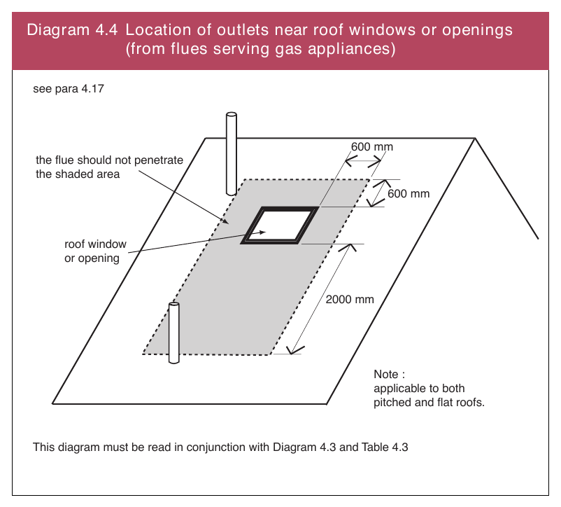
Provision of flues
4.22The flue and flue pipe for a gas appliance should –
(a)be designed and constructed following the provisions on the selection of components and the manner of their installation as given in paragraphs 4.23 to 4.28; or
(b)if the intended appliance is new and of a known type –
(i)be built using factory-made components that have been independently certified as achieving a performance at least equal to that corresponding to the designation given in Table 4.4; and
(ii)be installed in accordance with the provisions of paragraphs
4.25to 4.28 and Section 2, as relevant, and in accordance with the appliance manufacturer's and component manufacturer's installation instructions.
Page 63
#Source page 63
(1)The designation of chimney products is described in Appendix B. The BS EN for the product should specify its full designation and marking requirements.
(2)These are default designations. Where appliance manufacturer’s installation instructions specify a higher designation, this should be complied with.
| Appliance type | Minimum designation(1)(2) | |
|---|---|---|
| Boiler: open-flue | Natural draught Fanned draught Condensing | T250 N2 D 1 O T250 P2 D 1 O T140 P2 W 1 O |
| Boiler: room-sealed | Natural draught Fanned draught Condensing | T250 N2 D 1 O T250 P2 D 1 O T140 P2 W 1 O |
| Gas fire | Radiant/convector, ILFE or DFE | T250 N2 D 1 O |
| Air heater | Natural draught Fanned draught SE-duct | T250 N2 D 1 O T250 P2 D 1 O T250 N2 D 1 O |
| Notes: |
Flue pipe components
4.23The components for a flue pipe should be –
(a)any of the options in paragraph 2.26;
(b)a sheet metal pipe as described in BS EN 1856: 2;
(c)a fibre cement pipe as described in BS EN 1857; or
(d)any other material or component that has been certified as suitable for this purpose.
Flue block chimneys
4.24A flue block chimney should be constructed from either –
(a)a factory-made flue block system primarily designed for solid fuel, as described in paragraphs 2.23 and 2.24; or
(b)a factory-made flue block system comprising of straight blocks, recess units, lintel blocks, offset blocks, transfer blocks and jointing materials complying with –
(i)BS EN 1858 for concrete flue blocks of at least class D2; or
(ii)BS EN 1806 for clay/ceramic flue blocks, with a performance class of at least FB4 N2.
4.25A flue block chimney should be installed with sealed joints in accordance with the flue block manufacturer's installation instructions. Where bends or offsets are required, these should be formed using matching factory-made components. Flue blocks, which are not intended to be bonded into surrounding masonry, should be supported and restrained in accordance with the manufacturer's installation instructions.
Page 64
#Source page 64
Location and shielding of flues
4.26The combustible materials in the building fabric should be protected from the heat dissipation from a flue in accordance with the provisions of Table 4.5.
4.27Where a flue pipe or flue penetrates a fire compartment wall or floor, it must not breach the fire separation requirements of Part E of the Building Regulations.
4.28A flue pipe and factory-made chimney should be guarded where –
(a)they present a burn hazard to people that is not immediately apparent; or
(b)they could be at risk of damage.
| Table 4.5 Protecting buildings from hot flues | |
|---|---|
| Flue gas within | Protection measures |
| Flue pipe | A flue should be not less than 25 mm from any combustible material, measured from the outer surface of the flue wall, or the outer surface of the inner wall in the case of multi-walled products. Where passing through a combustible wall, floor or roof (other than a compartment wall, floor or roof) a non-combustible sleeve enclosing the flue pipe or flue should be used which has a 25 mm airspace to the relevant flue wall. The airspace can be wholly or partially filled with non-combustible insulating material |
| Factory-made chimney complying with BS EN 1856-1 | |
| Factory-made chimney complying with - BS EN 1856-1 and BS EN 1856-2 | Install in accordance with Section 1, Paragraph 2.37 |
| Masonry chimney | Provide 25 mm of masonry between the flue and any combustible material |
| Flue block chimney | Provide flue block walls with a thickness of not less than 25 mm |
Lining or relining flues in chimneys
4.29The lining or relining of a flue serving a gas appliance should be carried out in accordance with the provisions given in paragraphs 2.21, 2.22 and 3.20 or by using a flexible stainless steel liner independently certified as complying with BS EN 1856: 1 and BS EN 1856: 2.
4.30A flexible metal flue liner should be installed in one complete length without joints within the chimney. Other than for sealing at the top and the bottom, the space between the chimney and the liner should be left empty unless this is contrary to the manufacturer's instructions.
4.31Where a double skin flexible flue liner is used it should be installed in accordance with the manufacturer's installation instructions. A liner which complies with the recommendations of BS EN 1856: 1 and BS EN 1856: 2, should be installed in accordance with BS 5440: 1.
Debris collection space for chimneys
#Source page 65
Diagram 4.5 Base for back boiler
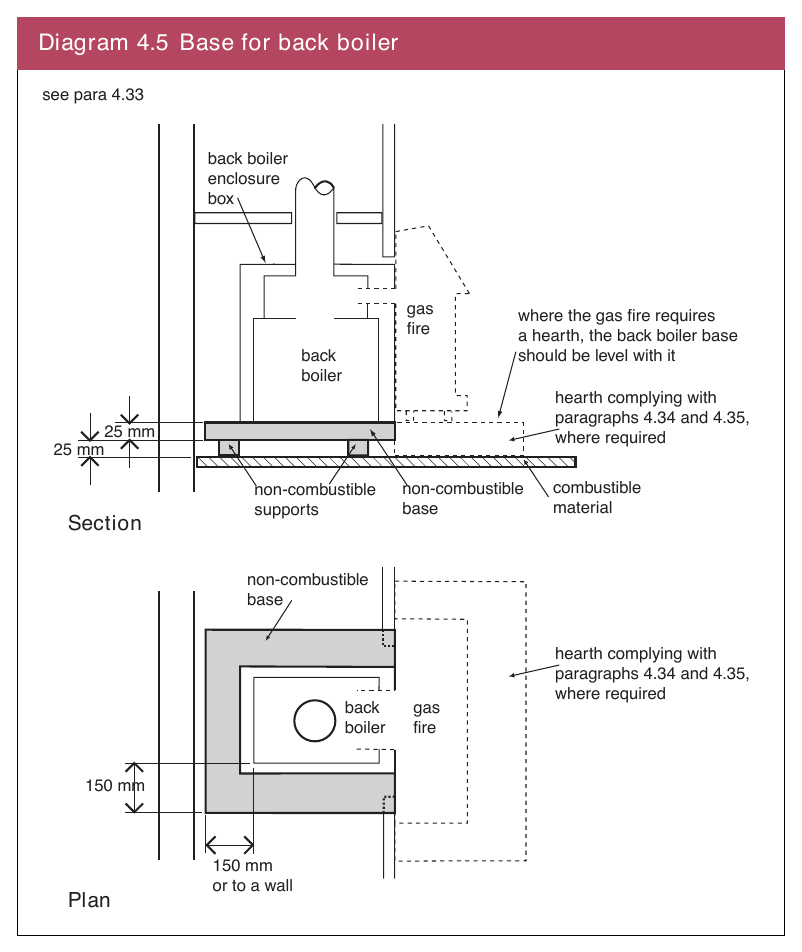
Debris collection space for chimneys
4.32A debris collection space should be provided at the base of a chimney unless it is lined, constructed of flue blocks, or is a factory-made metal chimney with a flue box. The space should have a volume of not less than 12 litres and a depth of not less than 250 mm below the point where flue gases discharge into the flue. The space should be readily accessible for clearance of debris.
For gas fires of the type illustrated in Diagram 4.1(a) and (b), there should be at least 50 mm clearance between the end of the appliance spigot and any surface.
Bases for back boilers
4.33 A back boiler should be adequately protected to shield the fabric of the building from heat by standing it on –
(a)a hearth intended for a solid fuel appliance. See Diagram 3.7(a); or
(b)unless otherwise stated in the manufacturer's instructions, a base complying with Diagram 4.5.
Hearths for gas burning appliances
#Source page 66
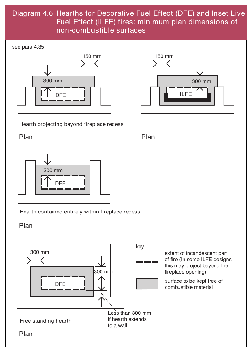
Hearths for gas burning appliances
4.34A gas-fired appliance should be placed on a hearth unless –
(a)it is installed so that every part of any flame or incandescent material should be not less than 225 mm above the floor; or
(b)the manufacturer's instructions state that a hearth is not required.
4.35Where a hearth is required, instructions on its minimum plan dimensions are given in Diagrams 4.6 and 4.7. The hearth should comprise of at least a layer of non-combustible, non-friable material not less than 12 mm thick. The edges of the hearth should be marked by a change in level to provide a warning to the building occupants and to discourage combustible floor finishes such as carpet being laid too close to the appliance.
Diagram 4.6 Hearths for Decorative Fuel Effect (DFE) and Inset Live Fuel Effect (ILFE) fires: minimum plan dimensions of non-combustible surfaces
300mm DFE
| extent of incandescent part of fire (In some ILFE designs this may project beyond the fireplace opening) surface to be kept free of combustible material | |
|---|---|
| Free standing hearth Plan | if hearth extends to a wall |
Shielding of appliances
#Source page 67
Diagram 4.8 Shielding of appliances
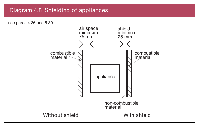
Diagram 4.7 Hearths for other appliances: plan dimensions of non-combustible surfaces
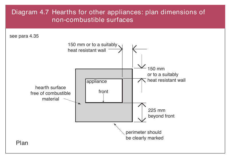
Shielding of appliances
4.36A gas-fired appliance should be located where accidental contact is unlikely and it should be surrounded by a non-combustible surface which provides adequate separation from combustible materials. The appliance should be installed –
(a)with a shield of non-combustible material with a minimum thickness of 25 mm, between the appliance and the combustible material. See Diagram 4.8; or
(b)with an air space of not less than 75 mm between the appliance and the combustible material. See Diagram 4.8.
4.37A gas-fired appliance that is CE marked as compliant with the Gas Appliances (Safety) Regulations 1995, should be installed in accordance with the manufacturer’s instructions.
Class of oil
#Source page 68
Section 5 Oil burning appliances (including liquid biofuel) with a rated heat output up to 45 kW
This section sets out the additional provisions that should be met for oil burning appliances over and above those given in Section 2.
Class of oil
5.1
The provisions in this Section are relevant to combustion installations designed to burn oils meeting the specifications for Class C2 (Kerosene) and Class D (Gas oil) given in BS 2869, liquid biofuel conforming to BS EN 14213 and blends of mineral oil and liquid biofuel.
Appliances fitted in bedrooms, bathrooms and shower rooms
5.2An open-flued oil-fired appliance should not be installed in a bedroom, bathroom or shower room as there is an increased risk of carbon monoxide poisoning. If a combustion appliance must be installed in such a room then a room-sealed appliance should be provided.
Air supply and ventilation
Air supply to appliances
5.3The permanently open air vent for an oil burning appliance should have the free area as given in Diagram 5.1. However, if the manufacturer's installation instructions require a greater area of permanently open air vent then the manufacturer's advice should be followed.
Example of calculation of free area of air vent using Diagram 5.1
5.4An open-flued appliance is installed in an appliance compartment such as a cupboard, which is ventilated via an adjoining room. The appliance has a rated output of 11 kW.
Air for combustion and the safe operation of the flue enters the adjoining room via vent A, which has an area – (11 – 5 ) x 550 = 3300 mm2
The cooling air for the appliance compartment is exhausted through vent B which has an area – 11 x 1100 = 12100 mm2
All of the air for combustion and the safe operation of the flue as well as cooling air enters the appliance compartment through vent C which has an area –
11x 1650 = 18150 mm2
Page 69
#Source page 69
Diagram 5.1 Free areas of permanently open air vents for oil-fired appliance installations see para 5.3
| Appliance in a room or space | Open-Flued Open-flued appliance A A = 550 mm² per kW output (see Note 3 and 5) Section | Room-Sealed Room-sealed appliance No vent needed Plan |
| Appliance in an appliance compartment ventilated via an adjoining room or space | B A C A = 550 mm² per kW output (see Note 3 and 5) B = 1100 mm ² per kW output C = 1650 mm² per kW output Section | F G F = 1100 mm² per kW input (net) G = F Plan |
| Appliance in an appliance compartment ventilated direct to outside | D E D = 550 mm² per kW output E = 1100 mm ² per kW output Section | H J H = 550 mm² per kW output J = H Plan |
| Notes: 1. A, D, E, H and J are permanently open vents to the outside. B, C, F and G are permanently open vents between an appliance compartment and a room or space. 2. The area given above is the free area of the vent(s) or the equivalent free area for ventilators of more complex design. 3. Vent A should be increased by a further 550 mm ² per kW output if the appliance is fitted with a draught break. 4. Vents at C, E, G, and J are low level vents. Vents at B, D, F, and H are high level vents. 5. In older dwellings with an air permebability which is more than 5.0 m ³/h/m ² the first 5 kW (net) can be ignored. |
Flues and chimneys
#Source page 70
Size of flues (other than balanced flues and flues designed to discharge through or adjacent to walls)
5.5A flue should be sized to suit the intended appliance such that it ensures an adequate discharge velocity to prevent flow reversal problems but does not impose excessive flow resistance.
5.6The flue pipe should be the same size as the appliance flue outlet and the flue should be the same cross-sectional area as the appliance flue outlet unless the appliance manufacturer specifies otherwise.
5.7The flue in a masonry or flue block chimney should be the same size as the appliance flue outlet or of a larger size that should allow for the later insertion of a suitable flexible flue liner matching the appliance to be installed.
Outlets from flues and flue heights
5.8The outlet from a flue should be so situated externally as to allow the safe dispersal of the products of combustion, the correct operation of a natural draught flue and, if a balanced flue, the intake of air. The flue outlet should be located as shown in Diagram 5.2 and Table 5.1.
5.9A flue outlet should be protected by a guard where –
(a)a person could easily come into contact with it; or
(b)it could be damaged.
5.10If a flue outlet is in a vulnerable position, such as where the flue discharges at a point within reach of the ground, a balcony, a veranda or window, it should be designed to prevent the entry of any matter that could obstruct the flow.
Page 71
#Source page 71
Diagram 5.2 Location of outlets from flues serving oil-fired appliances
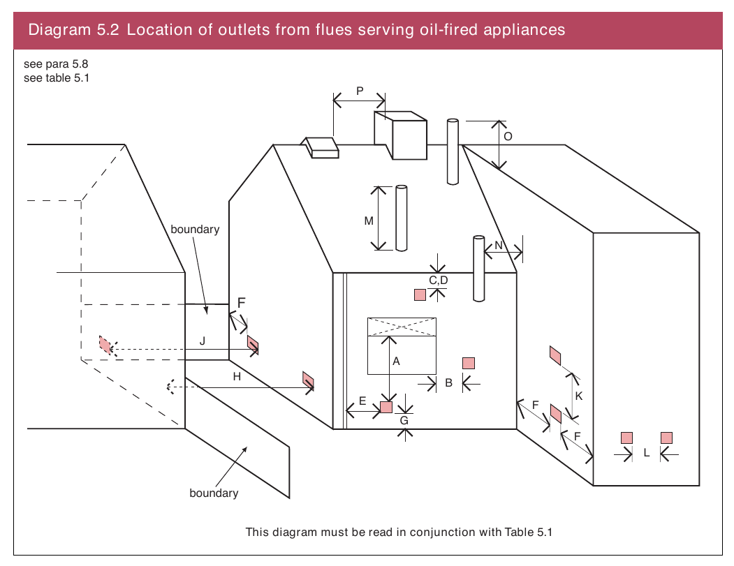
Page 72
#Source page 72
| Table 5.1 | Location of outlets for flues serving oil-fired appliances | ||
|---|---|---|---|
| Distance | Location of outlet (1)(2)(3) | Minimum separation distances for terminals (mm) | |
| Appliance with pressure jet burner | Appliance with vaporising burner | ||
| A | Below an opening (4)(5) | 600 | Should not be used |
| B | Horizontally to an opening(4)(5) | 600 | Should not be used |
| C | Below a plastic/painted gutter, drainage pipe or eaves if combustible material is protected(6) | 75 | Should not be used |
| D | Below a plastic/painted gutter, drainage pipe or eaves if combustible material is not protected | 600 | Should not be used |
| E | From vertical sanitary pipework | 300 | Should not be used |
| F | From an external or internal corner or from a surface or boundary alongside the terminal | 300 | Should not be used |
| G | Above ground or balcony level | 300 | Should not be used |
| H | From a surface or boundary facing the terminal | 600 | Should not be used |
| J | From a terminal facing the terminal | 1200 | Should not be used |
| K | Vertically from a terminal on the same wall | 1500 | Should not be used |
| L | Horizontally from a terminal on the same wall | 750 | Should not be used |
| M | Above the highest point of an intersection with the roof | 600(7) | 1000(8) |
| N | From a vertical structure to the side of the terminal | 750(7) | 2300 |
| O | Above a vertical structure which is less than 750 mm (pressure jet) or 2300 mm (vaporising jet) horizontally from the side of the terminal | 600(7) | 1000(8) |
| P | From a ridge terminal to a vertical structure on the roof | 1500 | Should not be used |
| Notes: (1) (2) (3) (4) (5) (6) (7) (8) | A terminal should only be positioned on a wall where an appliance has been approved for such configuration when tested in accordance with BS EN 303–1 or OFTEC standards OFS A100 or OFS A101. The terminating point of any flue should be not less than 1800 mm from an oil storage tank unless a fire wall as described in Section 6 is provided between the tank and the flue termination. A terminal should be positioned so as to avoid products of combustion accumulating in stagnant pockets around the building or entering into buildings. An opening means an openable element, such as an openable window, or a permanent opening such as a permanent open air vent. Notwithstanding the dimensions above, a terminal should be not less than 300 mm from combustible material, e.g. window frame. Combustible material should be protected by the fitting of a heat shield at least 750 mm wide. Outlets for vertical balanced flues in locations M, N and O should be in accordance with the manufacturers instructions. Where a terminal is used with a vaporising burner, it should be at least 2300 mm horizontally from the roof. |
Page 73
#Source page 73
Flues for oil-fired appliances
5.11The satisfactory provision of a flue and flue pipe depends upon the flue gas temperature to be expected in normal service. Separate guidance is given according to whether the proposed installation should have a flue gas temperature not greater than 250ºC, or greater than 250ºC, as measured, for example, in accordance with OFTEC Standards A100 or A101. Suitable chimney systems may then be selected based on their performance designation having been tested in accordance with the relevant European standard.
5.12The flue gas temperature depends upon the appliance type and the age of its design. Older and second hand appliances are likely to produce flue gas temperatures greater than 250ºC.
Boilers bearing the CE marking, indicating compliance with the Boiler (Efficiency) Regulations 1993, normally have a flue gas temperature not greater than 250ºC. Condensing oil-fired appliances should normally produce flue gas temperatures well below 100ºC.
Information for individual appliances should be sought from the manufacturer's installation instructions, the manufacturer, or OFTEC.
Where this information is not available, a flue should be constructed for an assumed flue gas temperature greater than 250ºC.
Provisions for flue gas temperatures greater than 250ººC
5.13The chimney, flue and flue pipe for an oil burning appliance, with a flue gas temperature greater than 250ºC, should be –
(a)in accordance with the provisions given in Sections 2 and 3 for a masonry or flue block chimney; or
(b)a factory-made metal chimney in accordance with Section 2.
Provisions for flue gas temperatures not greater than 250ººC
5.14The chimney, flue and flue pipe for an oil burning appliance, with flue gas temperatures not greater than 250ºC, should –
(a)be constructed in accordance with the provisions on the selection of components and the manner of their installation given in paragraphs 5.15 to 5.20; or
(b)if the intended appliance is of known type –
(i)be built using factory-made components that have been independently certified as achieving a performance at least equal to that corresponding to the designation given in Table 5.2 for the intended appliance type, when tested to an appropriate European chimney standard; and
(ii)be installed in accordance with the provisions of paragraphs 5.17 to 5.20 and Section 1, as relevant, and in accordance with the appliance manufacturer's and component manufacturer's installation instructions.
Flue pipe components
#Source page 74
| than 250ºC | ||
|---|---|---|
| Appliance type | Fuel oil | Minimum designation |
| Condensing boiler, including combination boiler, range cooker, range cooker/boiler – with pressure-jet burners | Class C2 oil (kerosene) Liquid biofuel conforming to EN 14213 | T120 N2 W1 O |
| Condensing boiler, including combination boiler, range cooker, range cooker/boiler – with pressure-jet burners | Class D oil (heating oil) | T160 N2 W2 O |
| Non-condensing boiler, including combination boiler, range cooker, range cooker/boiler – with pressure-jet burners | Class C2 oil (kerosene) Liquid biofuel conforming to EN 14213 | T250 N2 D1 O |
| Non-condensing boiler, including combination boiler, range cooker, range cooker/boiler – with pressure-jet burners | Class D oil (heating oil) | T250 N2 D2 O |
| Cooker and room heater – with vaporising burner | Class C2 oil (kerosene) | T160 N2 D1 O |
| Cooker and room heater – with vaporising burner | Class D oil (heating oil) | T250 N2 D2 O |
| Notes: |
1.The designation of chimney products is described in Appendix B. The BS EN for the product should specify its full designation and marking requirements.
2.These are default designations. Where the appliance manufacturer’s installation instructions specify a higher designation, this should be complied with.
3.Refer to the appliance manufacturer regarding the suitability of the appliance and flue system for use with oil / bio-liquid blends.
Flue pipe components
5.15 A flue pipe should be constructed using the following components –
(a)any of the relevant options in paragraph 2.26;
(b)sheet metal as described in BS EN 1856: 2;
(c)fibre cement pipes as described in BS EN 1857; or
(d)any other component that has been certified as suitable for this purpose.
Page 75
#Source page 75
Flue block chimneys
5.16A flue block chimney should be constructed from either –
(a)a factory-made flue block system primarily designed for solid fuel, as described in paragraphs 2.23 and 2.24; or
(b)a factory-made flue block system comprising of straight blocks, recess units, lintel blocks, offset blocks, transfer blocks and jointing materials complying with –
(i)BS EN 1858 for concrete flue blocks; or
(ii)BS EN 1806 for clay/ceramic flue blocks, with a performance not less than the designation given in Table 5.2 for the intended appliance type.
5.17A flue block chimney should be installed with sealed joints in accordance with the flue block manufacturer's installation instructions. Where bends or offsets are required, these should be formed using matching factory-made components. Flue blocks that are not intended to be bonded into surrounding masonry should be supported and restrained in accordance with the manufacturer's installation instructions.
Location and shielding of flues
5.18Where the flue gas temperature is not expected to exceed 250ºC the combustible materials in the building fabric should be protected from the heat dissipation from a flue in accordance with the provisions of Table 5.3.
5.19Where a flue pipe or flue penetrates a fire compartment wall or floor, it must not breach the fire separation requirements of Part E of the Building Regulations.
5.20A flue pipe flue and factory-made chimney should be guarded where –
(a)they present a burn hazard to people that is not immediately apparent; or
(b)they could be at risk of damage.
Lining or relining flues in chimneys
#Source page 76
| Table 5.3 Protecting buildings from hot flue gas temperatures not greater than 250ºC | |
|---|---|
| Flue gas within | Protection measures |
| Flue pipe | A flue should be not less than 25 mm from any combustible material, measured from the outer surface of the flue wall, or the outer surface of the inner wall in the case of multi-walled products. Where passing through a combustible wall, floor or roof (other than a compartment wall, floor or roof) a non-combustible sleeve enclosing the flue pipe or chimney should be used which has a 25 mm airspace to the relevant flue wall. The airspace can be wholly or partially filled with non-combustible insulating material |
| Factory-made chimney designated in accordance with BS EN 1856: 1 | |
| Factory-made chimney designated in accordance with BS EN 1856: 1 and BS EN 1856: 2 | Install in accordance with Section 2 paragraph 2.37 of this Technical Booklet |
| Masonry chimney | Provide not less than 25 mm of masonry between the flues and any combustible material |
| Flue block chimney | Provide flue block walls with a thickness of not less than 25 mm |
| Flue assemblies for room-sealed appliances | (a) flues passing through combustible walls should be surrounded by insulation material not less than 50 mm thick. (b) provide a clearance of not less than 50 mm from the edge of the flue outlet to any combustible wall cladding |
Lining or relining flues in chimneys
5.21Where the flue gas temperature is expected to be greater than 250ºC the liner should be –
(a)as per the provisions in paragraph 2.22;
(b)as per the provisions in paragraph 3.20; or
(c)a flexible stainless steel liner designated in accordance with BS EN 1858.
5.22Where the flue gas is expected not to be greater than 250ºC the liner should be –
(a)any of the linings described in 5.21 above; or
(b)if the appliance is new and of known type, flue lining systems that have been independently certified as having a performance not less than that corresponding to the designation given in Table 5.2 for the intended appliance type.
5.23A flexible metal flue liner should be installed in one complete length without joints within the chimney. Other than for sealing at the top and the bottom, the space between the chimney and the liner should be left empty unless this is contrary to the manufacturer's instructions. Double skin flexible flue liners should be installed in accordance with manufacturer's installation instructions. BS 715 liners should be installed in accordance with BS 5440: Part 1.
Page 77
#Source page 77
Debris collection space for chimneys
5.24A debris collection space should be provided at the base of a chimney unless it is lined or constructed of flue blocks, or is a factory-made metal chimney with a flue box. The space should have a volume of not less than 12 litres and a depth of not less than 250 mm below the point where flue gases discharge into the flue and be readily accessible for the clearance of debris.
Flues for appliances burning Class D (Gas oil) fuel
5.25A flue serving an appliance burning Class D (Gas oil) fuel should be made of materials which are resistant to the acids of sulphur, i.e. minimum flue designation ‘D2’ for non-condensing appliances or ‘W2’ for condensing appliances, according to the designation system in BS EN 1443 and related flue standards.
Hearths for oil-fired appliances
5.26Where an appropriate test procedure, such as in OFTEC Standards A100, A101 and A102, shows that the temperature of the floor below an appliance should be not greater than 100ºC, a rigid, imperforate and non-absorbent sheet of non-combustible material, such as a steel tray, should be provided. This may be included as an integral part of the appliance.
5.27Where the appliance will cause the temperature of the floor below it to be greater than 100ºC, a hearth of solid non-combustible material should be provided. It should –
(a)have plan dimensions not less than those shown in Diagram 3.7; and
(b)be made of solid non-combustible material, such as concrete or masonry, not less than 125 mm thick, including the thickness of any non-combustible floor and/or decorative surface.
5.28Combustible materials should not be placed beneath a constructional hearth unless –
(a)there is an air space of not less than 50 mm between the underside of the hearth and the combustible material; or
(b)the combustible material is not less than 250 mm below the top of the hearth. See Diagram 3.8.
5.29The appliance should not be placed closer to the edges of the hearth nor closer to any combustible material that is laid over the hearth than the distances shown in Diagram 5.3. The perimeter of this safe region should be marked by a change in level to provide a warning to the building occupants and to discourage combustible floor finishes such as carpet from being laid too close to the appliance.
Shielding of oil-fired appliances
#Source page 78
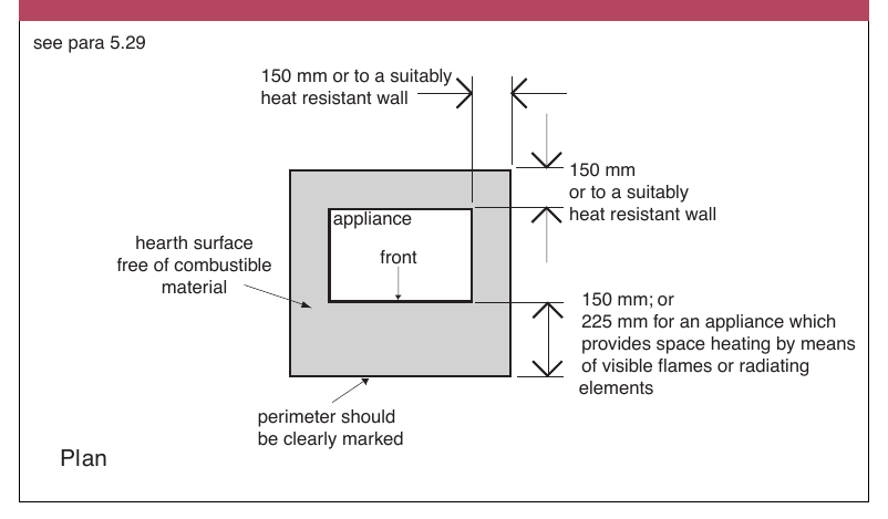
Diagram 5.3 Location of an oil-fired appliance in relation to its hearth. Minimum dimensions of the heat resistant material in the hearth and the clear zone of non-combustible surface
150mm; or 225 mm for an appliance which provides space heating by means of visible flames or radiating elements
Shielding of oil-fired appliances
5.30An oil-fired appliance should be located where accidental contact is unlikely and it should be surrounded by a non-combustible surface which provides adequate separation from combustible materials. The appliance should be installed –
(a)with a shield of non-combustible material, having a minimum thickness of 25 mm, between the appliance and the combustible material. See Diagram 4.8; or
(b)with an air space of not less than 75 mm between the appliance and the combustible material. See Diagram 4.8.
5.31An appliance independently certified as having a surface temperature, during normal operation of not greater than 100ºC (as shown using an appropriate test procedure such as in OFTEC Standards A100, A101 or A102) should not require shielding. Such certification should be prominently displayed on the appliance.
Oil storage installations
#Source page 79
Section 6 Liquid fuel (including liquid biofuel) storage and supply
Oil storage installations
Heating oil
6.1The provisions given in this part of the Section are related to heating oil that is Class C2 (kerosene) or Class D (gas oil) as specified in BS 2869, liquid biofuel conforming to EN 14213 and blends of mineral oil and liquid biofuel.
Protective measures against fire
6.2An above ground oil storage tank should be placed on a hard surface constructed of concrete or paving slabs not less than 42 mm thick. The hard surface should extend beyond the perimeter of the tank, or its external skin if it is an integrally bunded type, by not less than 300 mm.
The protection of an above ground or semi-buried oil tank from a fire, which may start in a building or beyond the site boundary, should be in accordance with the provisions given in Table 6.1.
Detailed provisions for a buried tank are not given in this Technical Booklet but it should be installed in accordance with the recommendations of BS 5410.
6.3A fire wall should be so constructed that it does not pose a danger to people around it.
Automatic isolation
6.4The fuel pipework should be resistant to the effects of fire and be fitted with a fire valve system where it enters the building, in accordance with the relevant recommendations in BS 5410: Part 1, Sections 8.2 and 8.3.
Control of oil pollution
#Source page 80
| Table 6.1 Fire protection for oil storage tanks | |
|---|---|
| Location of tank | Protective measures |
| 1800 mm or more from a building | No protection required |
| Less than 1800 mm from any part of a building | Any eaves less than 1800 mm from the tank should have 30 minutes fire resistance for integrity and insulation extending 300 mm beyond each side of the tank, and either (a) any part of the building wall less than 1800 mm from the tank should be imperforate(1) with a minimum 30 minutes fire resistance in terms of insulation, integrity and stability to internal fire; or (b) provide a fire wall(2) between the tank and any part of the building which is less than 1800 mm from the tank. The fire wall should extend not less than 300 mm higher and 300 mm wider than the tank. |
| 750 mm or more from a boundary | No protection required |
| Less than 750 mm from a boundary | Provide a fire wall(2) between the tank and the boundary or a boundary wall, which has a minimum of 30 minutes fire resistance in terms of insulation, integrity and stability to fire on either side. The fire wall or fire resistant boundary wall must extend not less than 300 mm higher and 300 mm beyond the ends of the tank. |
| Notes: (1) Excluding small openings such as air bricks, etc. (2) Fire walls should be imperforate non-combustible walls or screens, such as a masonry wall or fire-rated composite panel screens. 3. The terminating point of any flue should be not less than 1800 mm from an oil storage tank unless a fire wall as described in (b) above is provided between the tank and the flue termination. |
Control of oil pollution
6.5Where Regulation 76 in Part L applies, the oil should be stored in an integrally bunded prefabricated tank. The bund should have a capacity of not less than 110% of the tank it contains.
Oil tank construction
6.6An oil storage tank should be constructed in accordance with the recommendations of OFS T100: 2008 for polyethylene oil storage tanks or OFS T200: 2010 for steel oil storage tanks.
Liquefied Petroleum Gas (LPG) storage installations
#Source page 81
The provisions in this part of the Section are limited to LPG storage installations with a capacity not greater than 1.1 tonnes.
Tank location and protective measures
6.7An LPG storage installation with a capacity not greater than 1.1 tonnes, comprising of one tank standing in the open air, should be installed in accordance with the LP Gas Association, Code of Practice 1: Bulk LPG Storage at Fixed Installations: Part 1(2009), and the following paragraphs.
6.8The LPG tank should be installed in the open air and not within an open pit. The tank should be adequately separated from buildings, the boundary and any fixed sources of ignition to enable safe dispersal of the gas in the event of venting or leaks. If there is a fire at any of these locations these measures should reduce the risk of the fire spreading.
6.9The tank should be placed so that the minimum separation distances given in Table 6.2 and shown in Diagram 6.1 are achieved. Drains, gullies and cellar hatches within the separation distances should be protected from gas entry.
6.10The LPG tank should be sited such that there is a clear line of sight between the tank and the delivery vehicle to ensure that the person in control of the product transfer can quickly detect any problem at either point. If this cannot be achieved a remote fill point for the tank should be provided in clear view of the point at which the delivery vehicle is normally parked.
6.11Combustible materials, including weeds, long grass, deciduous shrubs and trees, should be removed from an area around the tank for a distance equal to that given in Table 6.2, Column (B).
6.12Where a visual screen is to be erected to hide an LPG tank, (e.g. at domestic installations), it should not interfere with the ventilation and should only be located at one side of the tank. For the purpose of such screening, any evergreen shrubs, trees or a non-flammable open ranch type fence should be located at a distance equal to that given in Table 6.2, Column (B) from the tank.
Fire walls for LPG installations
6.13Where a fire wall is part of a building or a boundary wall it should be located in accordance with Diagram 6.1(c) and if part of a building it should be constructed in accordance with Diagram 6.1(d).
6.14A fire wall should be imperforate and substantially constructed from brick, concrete or solid masonry. It should have a fire resistance (insulation, integrity and stability) of not less than 30 minutes, but where it forms part of a building, 60 minutes fire resistance.
Page 82
#Source page 82
6.15A fire wall should be not less than the height of the pressure release valve and should extend horizontally such that the separation distance specified in Table 6.2, Column (B) is maintained –
(a)when measured around the ends of the fire wall as shown in Diagram 6.1(b); or
(b)when measured to the ends of the fire wall as shown in Diagram 6.1(c), if the fire wall is the boundary or part of the building.
| Table 6.2 Fire protecti | on for LPG storage tanks | |
|---|---|---|
| Capacity of tank (tonnes) (A) | Minimum separation distances from buildings, boundaries or fixed sources of ignition | |
| To a tank with no fire wall or to a tank around a fire wall (B) | To a tank shielded by a fire wall (C) | |
| Not more than 0.25 | 2500 mm | 300 mm |
| More than 0.25 but not more than 1.10 | 3000 mm | 1500 mm |
Diagram 6.1 Separation or shielding of liquified petroleum gas tanks of up to 1.1 tonne capacity from buildings, boundaries and fixed sources of ignition
#Source page 83
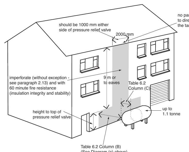
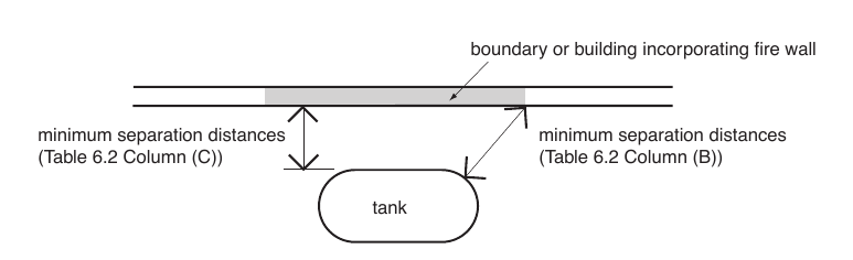
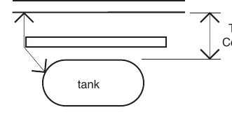
tank
Diagram 6.1 Separation or shielding of liquified petroleum gas tanks of up to 1.1 tonne capacity from buildings, boundaries and fixed sources of ignition
see para 6.9, 6.13 and 6.15 (a) & (b) see table 6.2 columns (B) & (C) building boundary or building boundary or fixed source of ignition fixed source of ignition
Table 6.2
Table 6.2
Column (C)
Column (B)
(a)No fire wall (b) Separate fire wall
(c)Boundary incorporating fire wall or Building incorporating fire wall
(see also Diagram (d) below) no part of structure to directly over-hang the tank
(d) Fire wall is part of the building wall
Inspection
#Source page 84
Appendix A Inspection and testing of flues, chimneys and flue pipes
A.1 This Appendix only describes ways of checking a natural draught flue intended for open-flued appliances. The procedures described are only used to assess whether the flue in the chimney, the connecting flue pipe (and flue gas passages in the appliance) are free of obstruction and acceptably gas- tight. In addition, appliance performance tests, including flue spillage tests must be carried out when a gas-fired appliance is commissioned as required by the Gas Safety (Installation and Use) Regulations (Northern Ireland) 2004.
A.2 Tests on flues should be carried out at the most appropriate time during the building work. Where possible smoke tests should be performed when the structure of a chimney is visible and before the application of finishes such as plaster or dry lining that could obscure sight of smoke leakage during testing.
Inspection
Existing flues
A.3 A flue in an existing chimney can be obstructed by nests, debris resulting from deterioration of the structure (e.g. brickwork, flue lining material or pieces of chimney pot) and by soot and tar. A flue in an existing chimney may also leak as a result of holes or cracks appearing in the structure and linings, particularly at joints. The top, exposed part of a chimney is particularly prone to decay.
A.4 Prior to bringing a flue back into use, it should be checked by –
(a)Sweeping the flue. This is intended to clean the flue to demonstrate that it is essentially free from obstructions and to enable better visual inspection and testing of the flue. Tar deposits caused by burning wood may be especially hard to dislodge and must be removed. The debris that comes down the chimney when sweeping should be examined for excessive quantities of lining or brick that are signs that further repairs are necessary.
(b)Carrying out a visual inspection of the accessible parts to identify –
(i)deterioration in the structure, connections or linings which could affect the flue's gas-tightness and safe performance with the proposed combustion appliance. Examine the interior of the flue and the exterior of the chimney, including in the roof space. The presence of smoke or tar stains on the exterior of a chimney are signs of leaks that indicate damage;
(ii)modifications made whilst the flue was out of service, such as the fitting of a ventilator terminal, which would be incompatible with using the flue with the intended appliance; and
(iii)correct lining and lining sizes for the proposed new application.
Page 85
#Source page 85
(c)Performing checks where necessary to demonstrate that the flue is free from restriction. A visual check may be sufficient where the full length of the flue can be seen. In cases of doubt, a coring ball test should be carried out.
(d)Checking the operation and gas-tightness of the flue by carrying out a smoke test.
New masonry and flue block chimneys
A.5 Check during construction that liners are installed the right way up; with sockets facing upwards, and joints are sealed so that moisture and condensate should be contained in the chimney.
A.6 A flue in a new masonry chimney can be obstructed, particularly at bends, by debris left during construction, or by excess mortar falling into the flue or by jointing material extruded from between liners and flue blocks. The flue must be checked to demonstrate that it has been correctly constructed and is free of restrictions and acceptably gas-tight. The condition of a new flue prior to bringing it into use must be checked by –
(a)visually inspecting the accessible parts to check that the lining, liners or flue blocks are of the correct materials and of suitable size for the proposed application;
(b)performing checks where necessary to demonstrate that the flue is free from restriction. A visual check may be sufficient where the full length of the flue can be seen. In cases of doubt, a coring ball test should be carried out, or the flue swept, which may be more effective at removing flexible debris that might not be dislodged by a coring ball; and
(c)checking the operation and gas-tightness of the flue by carrying out a smoke test.
New factory-made metal chimneys
A.7 A checklist for the visual inspection of a newly completed factory-made metal chimney is given in BS EN 15287: 1 and additional checks or particular variants may be included in manufacturers installation instructions. Following inspection, the chimney should be subjected to a smoke test.
Relined flues
A.8 A flue which has been relined should be checked to show that it is free from restrictions, such as from surplus material and that it is acceptably gastight by using the same tests as would be applied in the case of a newly built flue. However, a flue that has been relined with a flexible metal liner in accordance with Section 4 of this Technical Booklet may be assumed to be unobstructed and acceptably gastight. It should be noted that the use of a coring ball or inappropriate sweeps brushes could seriously damage a flexible metal flue liner.
Flue test procedures
#Source page 86
Appliances
A.9 Where a combustion appliance is provided and connected up to the flue system as part of the work, the complete system of appliance and flue should be tested for gas-tightness in addition to testing the flue separately as above. For gas-fired appliances an appropriate spillage test procedure is given in BS 5440: Part 1 and for oil and solid fuel fired appliances suitable test procedures are given in BS 5410: 1 and BS EN 15287: 1 Annex O respectively.
Flue test procedures
Coring ball test
A.10 This test may be appropriate for proving the minimum diameter of circular flues. It may also be used to check for obstructions in square flues but will not detect obstructions in the corners. (A purpose made coring ball or plate may need to be used if the flue is rectangular.) It is not applicable to flue pipes and should not be used with flexible metal flue liners. It should be carried out before smoke testing.
A.11 A heavy ball, with a diameter about 25 mm less than that of the flue, is lowered on a rope from the flue outlet to the bottom of the flue. If an obstruction is encountered, the blockage should be removed and the test repeated.
Smoke testing
A.12 Where an existing flue is to be checked with a smoke test, it should first be swept.
A.13 Two smoke testing procedures are described below –
(a)Test I confirms the gastightness of the whole flue and may be used for one serving a solid fuel or oil-fired appliance or if there is any doubt over the condition of a gas flue; or
(b)Test II may be used where the flue is to serve a gas-fired appliance.
Neither test is a substitute for any spillage test required when commissioning the appliance. Other smoke testing procedures could be used where these form part of the procedure for the installation of an approved flue or relining system.
Smoke Test I
A.14 All doors and windows in the room served by the flue must be closed. The flue should first be warmed to establish a draught, e.g. with a blowlamp or electric heater. A suitable number of flue testing smoke pellets are placed at the base of the flue, such as in the fireplace recess or in the appliance if it is fitted, and ignited. When smoke starts to form, the base of the flue or fireplace opening must be sealed or the appliance closed, so that the smoke can only enter the flue. (For example, the recess opening should be closed off with a board or plate, sealed at the edges or, if the pellets are in the appliance, its doors, ashpit covers and vents should be closed).
Page 87
#Source page 87
A.15 Smoke should be seen to issue freely from the flue outlet or terminal. When this is established, the top of the flue should be sealed. The full length of the flue should then be checked, bearing in mind paragraph A.20, there should be no significant leakage. The test should be allowed to continue for at least 5 minutes. The closures at the top and bottom of the flue should then be removed.
Smoke Test II
A.16 All doors and windows in the room served by the flue must be closed. The flue should first be warmed to establish a draught. A suitable flue testing smoke pellet is ignited at the base of the flue or in the intended position of the appliance, so that the smoke is drawn into the flue with the rising draught. (If the pellet is placed in a recess at the base of the flue, the opening between the room and the recess should be partially closed, such as with a board, but an air entry gap of about 25 mm should be left at the bottom).
A.17 Smoke should be seen to issue freely from the flue outlet or terminal and not to spill back into the room. There should be no significant leakage of smoke from the length of the chimney inside or outside of the building.
A.18 Smoke Tests I and II are in line with the recommendations in BS 5440: Part 1.
Notes in relation to testing
A.19 Where warming of the flue is specified, this is intended to establish a draught, but this may take more than 10 minutes in the case of large or cold flues.
A.20 Appliances, where fitted, should not be under fire at the time of carrying out the test. During a smoke test, smoke should not emerge from the outlet of any other flue, as this indicates leakage between flues. When checking for smoke leakage from a flue it should be borne in mind that smoke from a faulty flue can emerge some distance away from the original fault. In such cases, the smoke could emerge from such places as barge overhangs in end of terrace dwellings or from window reveals in cavity walls.
A.21 The purpose of carrying out smoke testing is to check that flue gases should rise freely through the flue and to identify whether there are any faults, such as incorrectly sealed joints or damage that would cause the flue gases to escape into the dwelling.
A.22 It should be noted that smoke pellets create a pressure significantly higher than the pressure required in the product standards for natural draught chimneys and for flues having a gas-tightness designation of N1. Flues to this designation are permitted to have a leakage rate of up to 2 litre/s/m2 flue wall area. Some smoke leakage may therefore be seen during smoke tests and it can be a matter of expert judgment of whether leakage indicates failure.
EN 1234 – T 450 N2 D 1 G50
#Source page 88
Appendix B Informative – European chimney designations
B.1 This informative appendix provides a summary of the European chimney designation scheme. The essence of the scheme is a series of code letters based on the general chimney designation scheme of BS EN 1443, an example of which and their explanation is given below.
Designation
B.2 The designation of a chimney consists of –
EN 1234 – T 450 N2 D 1 G50
Number of corresponding chimney standard
Temperature class
Pressure class N or P or H
Resistance to condensate class, W (wet) or D (dry)
Corrosion resistance class
Sootfire resistance class G or O followed by distance to combustible materials
B.3 European chimney standards have been developed based on the material of the flue liner e.g. clay/ceramic, concrete, metal, and plastic. Some material based standards have adopted a different shortened designation e.g. for clay flue liners a designation Liner – EN 1457-300-A1-N2 means it is suitable for a chimney with the designation T600 N2 D 3 G, with a nominal size of 300 mm.
B.4 The designation of the corrosion resistance class of a metal chimney product is dealt with in BS EN 1856-1 and BS EN 1856-2 by a two-fold approach. A minimum material specification and thickness is allowed which is dependent on that which is permitted in member states regulations, where these exist. Products upon which a declaration has been made in this manner are designated Vm. The alternative approach involves the choice of one of three corrosion resistance tests. Products meeting the tests carry the designation V1, V2 or V3, as appropriate allow the product to be designated with the Corrosion resistance class 1, 2, or 3 respectively. The material specification still forms part of the overall designation, and appears alongside the ‘V’ letter, e.g. Vx-L40045. The material specification for the liner (or connecting pipe) is formed by the letter ‘L’ followed by five digits. The first two digits represent the material type and the last three digits represent the material thickness in multiples of 0.01 mm.
Page 89
#Source page 89
B.5 For the UK, guidance on the minimum material specification appropriate for the various applications in terms of corrosion resistance (solid fuel, gas and oil) is given in the UK National Annex to BS EN 1856: 1 and 2. For further examples of shortened designation refer to the specific product standards.
B.6 In selecting an appliance for a given chimney designation, the appliance, irrespective of the fuel used, is required to generate combustion products with characteristics equal or less than those designated for the chimney. When selecting a chimney suitable for a given appliance, any chimney with performance characteristics equal to or higher than those appropriate for the appliance may be used.
Temperature classes
B.7 Temperature classes are set out in Table B1 and expressed as ‘T’ followed by a number which is less than or equal to the nominal working temperature, i.e. the average flue gas temperature obtained during the nominal/rated output test (usually the maximum operating level).
| Table B1 Temperature classes | |
| Temperature class | Normal working temperature is less than or equal to |
| T080 | 80ºC |
| T100 | 100ºC |
| T120 | 120ºC |
| T140 | 140ºC |
| T160 | 160ºC |
| T200 | 200ºC |
| T250 | 250ºC |
| T300 | 300ºC |
| T400 | 400ºC |
| T450 | 450ºC |
| T600 | 600ºC |
Page 90
#Source page 90
Pressure classes
B.8 Pressure classes are set out in Table B2 and expressed as either ‘N’, ‘P’ or ‘H’ followed by either ‘1’ or ‘2’. N relates in general to natural draught chimneys i.e. operating under negative pressure where the value 1 or 2 allows for a different class of product; metal chimneys to BS EN 1856: 1 have the class N1. In the UK the value N2 should be assigned as a minimum to masonry chimneys. P and H relate to chimneys which operate under positive pressure e.g. for fan assisted applications and diesel generators respectively. The pressure designation depends on the gas- tightness it achieves, the lower number being the more onerous, the higher allowed leakage for positive pressure application being intended to external installations.
| Table B2 Pressure classes | ||
|---|---|---|
| Pressure class | Test pressure Pa | Gas tightness Maximum leakage rate L/s/m ² |
| N1 | 40 | 2.0 |
| N2 | 20 | 3.0 |
| P1 | 200 | 0.006 |
| P2 | 200 | 0.120 |
| H1 | 5000 | 0.006 |
| H2 | 5000 | 0.120 |
Condensate resistance classes
B.9 Condensate resistance class – expressed as either ‘W’ for wet or ‘D’ for dry operations. A product designated ‘W’, able to contain condensates within the flue, is aimed at condensing appliances. A product designated ‘D’ would usually have flue gas temperatures high enough to avoid condensate formation.
Sootfire resistance classes
B.10 Sootfire resistance class – expressed as either ‘G’ with sootfire resistance, or ‘O’ without. A product assigned the designation ‘G’ has been tested at 1000ºC for 30 minutes.
Distance to combustible material
B.11 The designation of the minimum distance from the outer surface of the chimney to combustible material is given as xx expressed in millimetres
(e.g. the distance ‘XX’ identified in paragraph 2.37 and Diagram 2.5).
Page 91
#Source page 91
Corrosion resistance classes
B.12 Corrosion resistance classes are set out in Table B3 – this is fuel dependant and expressed as 1, 2 or 3.
| Table B3 Corrosion resistance classes (from BS EN 1443) | |||
|---|---|---|---|
| Corrosion resistance class | 1 Possible fuel types | 2 Possible fuel types | 3 Possible fuel types |
| gas | gas: sulphur content ≤ 50 mg/m³ Natural gas L + H | gas Natural gas L + H | gas Natural gas L + H |
| liquid | kerosene: sulphur- content ≤ 50 mg/m³ | oil: sulphur-content ≤ 0.2 mass % kerosene: sulphur- content � 50 mg/m³ | oil: sulphur-content > 0.2 mass % kerosene: sulphur- content ≥ 50 mg/m³ |
| wood | — | wood in open fire places | wood in open fire places wood in closed stoves |
| coal | — | — | coal |
| peat | — | — | peat |
Page 92
#Source page 92
Appendix C Assessing air permeability of older dwellings in relation to permanent ventilation requirements
C.1 The minimum requirements for permanent ventilation for certain appliances depends on a knowledge of the air-tightness of the dwelling where they are to be installed. Dwellings built after 2008 are likely to have evidence of the air-tightness either through an individual air permeability test certificate or through representative testing of the same design of dwelling on the same housing development.
C.2 Older houses are unlikely to have been tested and may not always achieve an air permeability of less than 5.0 m3/(h.m2) at 50 Pa unless the building fabric has been substantially upgraded. That would include all or most of the following measures:
•Full double (or triple) glazing
•Effective closures on trickle vents and other controllable ventilation devices
•All external doors with integral draught seals and letter box seals
•Internal and external sealing around external doors and window frames
•Filled cavity or solid walls
•Impermeable overlay and edge sealing of suspended ground floors
•Careful sealing at junctions between building elements such as between walls and floors or ceilings
•Careful sealing around loft hatch
•Careful sealing around chimney or flue penetrations
•Careful sealing around internal soil pipe and overflow pipe for WC
•Careful sealing around domestic water and heating pipes passing into externally ventilated spaces
•Careful sealing of all service penetrations in the building fabric (electricity, gas, water, drainage, phone, TV aerial, etc.)
•All cable channels for light switches and power sockets sealed
•All cable entry for lighting and ceiling roses sealed. Recessed lighting should not penetrate ceilings separating loft spaces.
C.3 Failure to implement even a few of these measures will typically mean that the overall air permeability will probably exceed 5.0 m3/(h.m2) at 50 Pa. However, individual rooms in some older houses with solid walls and solid floors can be inherently air-tight when fitted with modern glazing. The situation may therefore need to be assessed with respect both to the overall dwelling and to the individual room where the appliance is to be fitted. If in doubt then assume that the air permeability is lower than 5.0 m3/ (h.m2) at 50 Pa and fit the appropriate permanent ventilation or seek specialist advice. Further information on sources of air leakage can be found in GPG224 Improving airtightness in dwellings published by the Energy Saving Trust.
Page 93
#Source page 93
Appendix D Informative – LPG cylinders
Diagram D1 Location of LPG cylinders
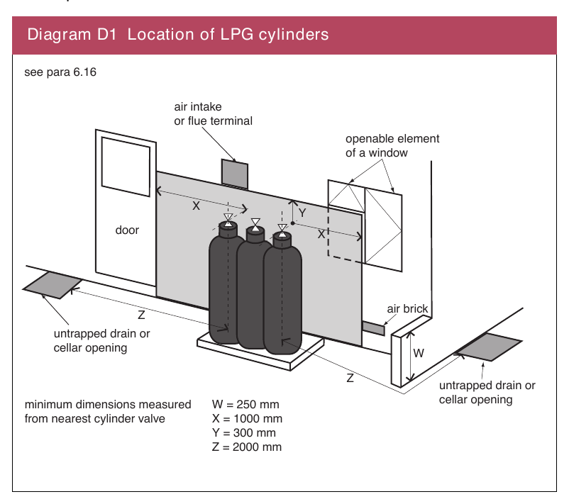
Location and support of LPG cylinders
D.1 The advice given in paragraph D.2 and Diagram D1 is informative and may be considered for an LPG storage installation that consists of a set of two or more cylinders having a combined capacity greater than 150 litres.
D.2 A cylinder should stand upright, be secured by straps or chains against a wall outside the building in a well ventilated position at ground level. It should be readily accessible, reasonably protected from physical damage and located where it does not obstruct exit routes from the building. A firm level base, such as concrete not less than 50 mm thick or paving slabs bedded on mortar should be provided. The cylinder valves should be not less than -
(a)1000 mm horizontally and 300 mm vertically from openings in the building or heat sources such as flue terminals and tumble-dryer vents; and
(b)2000 mm horizontally from drains without traps, unsealed gullies and cellar hatches, unless an intervening wall not less than 250 mm high is provided.
Page 94
#Source page 94
Appendix E Publications referred to
British Standards Institution BS EN ISO 1182: 2002 Reaction to fire tests for building products – Non-combustibility test. BS EN ISO 1716: 2002 Reaction to fire tests for building products – Determination of heat of combustion. BS EN 303: Heating boilers.
Part 1: 1999 Heating bolier with forced draught burners. Terminology, general requirements, testing and marking. AMD 16720
BS EN 449: 2002+A1: 2007 Specification for Dedicated Liquified Petroleum Gas Appliances. Domestic Flueless Space Heaters (Including Diffusive Catalytic Combustion Heaters).
BS EN 1443: 2003 Chimneys. General Requirements.
BS EN 1457: 1999 Chimneys. Clay/Ceramic Flue Liners. Requirements and Test Methods. AMD 14077.
BS EN 1806: 2006 Chimneys. Clay/Ceramic Flue Blocks for Single Wall Chimneys. Requirements and Test Methods.
BS EN 1856: Chimneys. Requirements for metal chimneys.
Part 1: 2009 System chimney products. Part 2: 2009 Metal liners and connecting flue pipes.
BS EN 1857: 2010 Chimneys. Components. Concrete Flue Liners. BS EN 1858: 2008 Chimneys. Components. Concrete flue blocks. BS EN 13141: 2004 Ventilation for buildings. Performance testing of components/products for residential ventilation. Externally and internally mounted air transfer devices. BS EN 13384: 1: 2002+A1:2008 Chimneys. Thermal and fluid dynamic calculation methods. Chimneys serving one appliance. BS EN 13501 Fire classification of construction products and building elements.
Part 1: 2007 +A1: 2008 Classification using test data from reaction to fire tests.
BS EN 13502: 2002 Chimneys. Requirements and test methods for clay/ceramic flue terminals.
BS EN 14213: 2003 Heating fuels. Fatty acid methyl esters (FAME). Requirements and test methods.
Page 95
#Source page 95
BS EN 14471: 2005 Chimneys. System chimneys with plastic flue liners. Requirements and test methods.
BS EN 15287 Chimneys. Design, installation and commissioning of chimneys. Chimneys for non roomsealed heating appliances.
BS EN 50291: 2010 Electrical apparatus for the detection of carbon monoxide in domestic premises. Test methods and performance requirements.
BS EN 50292: 2002 Electrical apparatus for the detection of carbon monoxide in domestic premises. Guide on the selection, installation, use and maintenance.
BS 41: 1973 Specification for cast iron spigot and socket flue or smoke pipes and fittings.
BS 476: Fire Tests on Building Materials and Structures.
Part 4: 1970 Non-combustibility Test for Materials AMD 2483 and AMD 4390.
Part 11: 1982 Method for Assessing the Heat Emission from Building Materials.
BS 715: 2005 Specification for metal flue boxes for gas-fired appliances not exceeding 20 kW.
BS 1251: 1987 Specification for open fireplace components.
AMD 8454
BS 2869: 2006 Specification for fuel oils for agricultural and industrial engines and boilers.
BS 5410: Code of Practice for Oil Firing.
Part 1: 1997 Installations up to 45 kW Output Capacity for Space Heating and Hot Water Supply Purposes, AMD 11022 and Corrigendum AMD 13155.
Part 2: 1978 Installations of 45 kW or Above Output Capacity for Space Heating, Hot Water and Steam Supply Purposes, AMD 3638 and AMD 13229.
BS 5440: Flueing and ventilation for gas appliances of rated input not exceeding 70 kW net (1st, 2nd and 3rd Family Gases).
Part 1: 2008 Specification for installation and maintenance of flues. AMD 13983
Part 2: 2009 Specification for installation and maintenance of ventilation for Gas Appliances. AMD 13368
BS 5871: Specification for installation and maintenance of gas fires, convector heaters, fire/back boilers and decorative fuel effect gas appliances.
Part 3: 2005 Decorative Fuel Effect Gas Appliances of Heat Input Not Exceeding 20 kW (2nd and 3rd Family Gases)
Chartered Institution of Building Services Engineers
#Source page 96
BS 6999: 1989 Specification for vitreous-enamelled low-carbon-steel flue pipes, other components and accessories for solid-fuel-burning appliances with a maximum rated output of 45kW AMD 8949
BS 8303: Installation of domestic heating and cooking appliances burning solid mineral fuels
Part 1: 1994 Design of installations
Part 2: 1994 Specification for Installing and Commissioning on Site
Part 3: 1994 Recommendations for Design and on Site Installation
Chartered Institution of Building Services Engineers
CIBSE Guide B: Heating, Ventilating, Air Conditioning and Refrigeration, (2005).
Energy Saving Trust
GPG224 Improving airtightness in dwellings (2005)
Oil Firing Technical Association (OFTEC)
OFS A100: 2004 Oil firing appliance standards. Heating boilers with atomising burners, outputs up to 70kW and maximum operating pressures of 3 Bar.
OFS A101: 2004 Oil firing appliance standards. Oil fired cookers with atomising or vaporising burners, with or without boilers, heat outputs up to 45kW.
OFS A102: 2004 Oil firing appliance standards. Roomheaters with atomising or vaporising burners, with or without boilers, heat outputs up to 25kW.
OFS T100: 2008 Oil firing equipment standard. Polyethylene oil storage tanks and tank bunds for distillate fuels.
OFS T200: 2007 Oil firing equipment standard. Steel oil storage tanks and tank bunds for use with distillate fuels, Lubrication Oils and Waste Oils.
Technical Booklet 2 Service and commissioning oil fired systems (pressure jet appliances).
Technical Booklet 4 Oil fires appliance and system installation requirements.
Technical Booklet 5 Service and commissioning oil fired systems (vaporising appliances)
LPG Gas Association
#Source page 97
Code of practice 1 Bulk LPG storage at fixed installations.
Part 1 Design, installation and operation of vessels located above ground. (2009) Part 2 Small bulk installations for domestic purposes (2000) Part 3 Examination and inspection (2006) Part 4 Buried/ Mounded LPG storage vessels (2008)
Code of Practice 24: Use of LPG Cylinders
Part 1: The use of propane cylinders at residential premises and similar
| premises | |
|---|---|
| DFP Technical Booklet B: 2012 | Materials and workmanship |
| DFP Technical Booklet K: 2012 | Ventilation |
| DFP Technical Booklet E: 2012 | Fire safety |
| DFP Technical Booklet N: 2012 | Drainage. |
Page 98
#Source page 98
Technical Booklets
The following list comprises the series of Technical Booklets prepared by the Department for the purpose of providing practical guidance with respect to the technical requirements of the Building Regulations (Northern Ireland) 2012.
| Technical Booklet B | Materials and workmanship |
| Technical Booklet C | Preparation of site and resistance to |
| contaminants and moisture | |
| Technical Booklet D | Structure |
| Technical Booklet E | Fire safety |
| Technical Booklet F1 | Conservation of fuel and power in |
| dwellings | |
| Technical Booklet F2 | Conservation of fuel and power in buildings other |
| than dwellings | |
| Technical Booklet G | Resistance to the passage of sound |
| Technical Booklet H | Stairs, ramps, guarding and protection from |
| impact | |
| Technical Booklet J | Solid waste in buildings |
| Technical Booklet K | Ventilation |
| Technical Booklet L | Combustion appliances and fuel storage |
| systems | |
| Technical Booklet N | Drainage |
| Technical Booklet P | Sanitary appliances, unvented hot water storage |
| systems and reducing the risk of scalding | |
| Technical Booklet R | Access to and use of buildings |
| Technical Booklet V | Glazing |
Any person who intends to demonstrate compliance with the Building Regulations by following the guidance given in a Technical Booklet is advised to ensure that the guidance is current on the date when plans are deposited or notice given to the district council.