Wales Approved Document B
Approved Document B: dwellinghouses
Library captured 10 September 2026 · Source updated 29 August 2026
The Building Regulations 2010
#Source page 1

The Building Regulations 2010
2006 edition incorporating 2010, 2016 and 2020 amendments - For use in Wales*
Main changes
#Source page 2
This Approved Document supports the requirements of Part B of Schedule 1 to the Building Regulations 2010.
The 2020 amendments to the Approved Document incorporate the following changes:
i. Amendments to Appendix A (Performance of materials, products and structures). The Approved Document has been amended to strengthen the provisions for assessments in lieu of fire tests. The requirements take effect on 31 December 2020. The 2016 edition will continue to apply to work started before 31 December 2020, or to work subject to a building notice, full plans application or initial notice submitted before 31 December 2020.
ii. The incorporation of the changes to the approved document included with circular WGC 003/2020 amendment slip: https://gov.wales/sites/default/files/publications/2020- 01/building-regulations-wales-circular-wgc-003-2020.pdf.
The amendment slip change relates to the definition of an external wall in Appendix E. The change made within the circular WGC 003/2020 came into force on the 13 January 2020.
This approved document gives guidance for compliance with the Building Regulations for building work carried out in Wales.
© Crown copyright Digital ISBN 978-1-80038-752-2 WG40904
Use of guidance
#Source page 8
Contents > Use of guidance > General introduction > Means of warning > Section 1 | 2 | 3 | 4 | 5 | 6 | 7 | 8 | 9 | 10 | 11 | 12 > Appendix A | B | C | D | E | F | G > Publications > Index
Use of guidance
Use of guidance
What is an Approved Document?
This Approved Document, which takes effect on 31 December 2020, has been approved and issued by Welsh Ministers for the purpose of providing practical guidance with respect to the requirements of Schedule 1 to and Regulations 7 and 37A of the Building Regulations 2010 (SI 2010/2214) for Wales.
At the back of this document is a list of all the documents that have been approved and issued by the Welsh Ministers for this purpose.
The intention of issuing Approved Documents is to provide guidance about compliance with specific aspects of the Building Regulations in some of the more common building situations. They include examples of what, in ordinary circumstances, may be reasonable provision for compliance with the relevant requirement(s) of the Building Regulations to which they refer.
If guidance in an Approved Document is followed there will be a presumption of compliance with the requirement(s) covered by the guidance. However, this presumption is not conclusive, so simply following guidance does not guarantee compliance in an individual case. It is also important to note that there may well be other ways of achieving compliance with the requirements. Thus unless required by regulation here is therefore no obligation to adopt any particular solution contained in this Approved Document if you would prefer to meet the relevant requirement in some other way. However, persons intending to carry out building work should always check with their Building Control Body (BCB), either the local authority or an Approved Inspector that their proposals comply with Building regulations.
The guidance contained in this Approved Document relates only to the particular requirements of the Building Regulations that the document addresses (see ‘Requirements’ below). However, building work may be subject to more than one requirement of the Building Regulations. In such cases the work will also have to comply with any other applicable requirements of the Building Regulations.
How to use this Approved Document
In this document the following conventions have been adopted to assist understanding and interpretation:
(a) Texts shown against a blue background are extracts from the Building Regulations or Building (Approved Inspectors etc.) Regulations, and set out the legal requirements of Building Regulations. It should be remembered however that, as noted above, building works must comply with all the other applicable provisions of Building Regulations.
Use of guidance
#Source page 9
Contents > Use of guidance > General introduction > Means of warning > Section 1 | 2 | 3 | 4 | 5 | 6 | 7 | 8 | 9 | 10 | 11 | 12 > Appendix A | B | C | D | E | F | G > Publications > Index
Use of guidance
(b)Details of technical publications referred to in the text of this document. A reference to a publication is likely to be made for one of two main reasons. The publication may contain additional or more comprehensive technical detail, which it would be impractical to include in full in this Document but which is needed to fully explain ways of meeting the requirements; or it is a source of more general information. The reference will be to a specified edition of the document. The Approved Document may be amended from time to time to include new references or to refer to revised editions where this aids compliance.
(c)When this approved document refers to a named standard or other document, the relevant version is listed in Appendix B. However, if the issuing body has revised or updated the listed version of the standard or document, you may use the new version as guidance if it continues to address the relevant requirements of the Building Regulations.
Where you can get further help
If you do not understand the technical guidance or other information set out in this Approved Document and the additional detailed technical references to which it directs you, there are a number of routes through which you can seek further assistance:
•The Welsh Government website: www.gov.wales
•The Planning Portal website:
•https://www.planningportal.co.uk/wales_en/info/7/building_control
•If you are the person undertaking the building work you can seek assistance either from your local authority building control service or from your approved inspector (depending on which building control service you are using, or intend to use, to certify compliance of your work with the requirements of the Building Regulations).
•Businesses registered with a competent person self-certification scheme may be able to get technical advice from their scheme operator.
•If your query is of a highly technical nature you may wish to seek the advice of a specialist, or industry technical body, in the area of concern.
Responsibility for compliance
It is important to remember that if you are the person (e.g. designer, builder, installer) carrying out building work to which any requirement of Building Regulations applies you have a responsibility to ensure that the work complies with any such requirement. The building owner may also have a responsibility for ensuring compliance with Building Regulation requirements and could be served with an enforcement notice in cases of non-compliance.
Other requirements
#Source page 10
Contents > Use of guidance > General introduction > Means of warning > Section 1 | 2 | 3 | 4 | 5 | 6 | 7 | 8 | 9 | 10 | 11 | 12 > Appendix A | B | C | D | E | F | G > Publications > Index
Use of guidance
Other requirements
The guidance contained in an Approved Document relates only to the particular requirements of the Regulations which that document addresses. The building work will also have to comply with the Requirements of any other relevant paragraphs in Schedule 1 to the Regulations.
There are Approved Documents which give guidance on each of the other requirements in Schedule 1 and on Regulation 7.
Limitation on requirements
In accordance with Regulation 8, the requirements in Parts A to D, F to K, N and P (except for paragraphs H2 and J7) of Schedule 1 to the Building Regulations do not require anything to be done except for the purpose of securing reasonable standards of health and safety for persons in or about buildings (and any others who may be affected by buildings or matters connected with buildings). This is one of the categories of purpose for which Building Regulations may be made.
Paragraphs H2 and J7 are excluded from Regulation 8 because they deal directly with prevention of the contamination of water. Parts E and M (which deal, respectively, with resistance to the passage of sound, and access to and use of buildings) are excluded from Regulation 8 because they address the welfare and convenience of building users. Part L is excluded from Regulation 8 because it addresses the conservation of fuel and power. All these matters are amongst the purposes, other than health and safety that may be addressed by Building Regulations.
Requirement for residential automatic fire suppression systems
This Approved Document provides guidance on compliance with the requirements for premises described in 37A of the Building Regulations to be provided with an automatic fire suppression system.
Materials and workmanship
Any building work which is subject to the requirements imposed by Schedule 1 to the Building Regulations shall be carried out in accordance with Regulation 7. Guidance on meeting these requirements on materials and workmanship is contained in Approved Document 7.
Building Regulations are made for specific purposes, primarily the health and safety, welfare and convenience of people and for energy conservation. Standards and other technical specifications may provide relevant guidance to the extent that they relate to these considerations. However, they may also address other aspects of performance or matters which, although they relate to health and safety etc., are not covered by the Building Regulations.
When an Approved Document makes reference to a named standard, the relevant version of the standard to which it refers is the one listed at the end of the publication. However, if this version has been revised or updated by the
Interaction with other legislation:
#Source page 11
Contents > Use of guidance > General introduction > Means of warning > Section 1 | 2 | 3 | 4 | 5 | 6 | 7 | 8 | 9 | 10 | 11 | 12 > Appendix A | B | C | D | E | F | G > Publications > Index
Use of guidance issuing standards body, the new version may be used as a source of guidance provided it continues to address the relevant requirements of the Regulations.
Interaction with other legislation:
Houses in multiple occupation
This guidance may also be applicable to the design and construction of dwellings which are considered to be ‘houses in multiple occupation’ (HMOs), as defined in the Housing Act 2004, providing there are no more than six residents in any self-contained dwelling. The licensing of HMOs is typically overseen by the Local Authority who may require additional precautions over and above this guidance. Technical guidance on the assessment of hazards from fire and preventive measures for HMOs is contained in the Housing Health and Safety Rating System Operating Guidance issued in February 2006 (ISBN: 978 185112 846 4).
The Workplace (Health, Safety and Welfare) Regulations 1992
The Workplace (Health, Safety and Welfare) Regulations 1992 contain some requirements which affect building design. The main requirements are now covered by the Building Regulations but for further information see: The Workplace (Health, Safety and Welfare) Regulations 1992, Approved Code of Practice and Guidance; The Health and Safety Commission, L24; published by HMSO 1992; ISBN: 0 11886 333 9.
The Workplace (Health, Safety and Welfare) Regulations 1992 apply to the common parts of flats and similar buildings if people such as cleaners, wardens and caretakers are employed to work in these common parts. Where the requirements of the Building Regulations that are covered by this Part do not apply to dwellings, the provisions may still be required in the situations described above in order to satisfy the Workplace Regulations.
The Construction (Design and Management) Regulations 2006
The purpose of this Approved Document is to provide guidance on the fire safety requirements for the completed building. It does not address the risk of fire during the construction work which is covered by the Construction (Design and Management) Regulations 2006 and the Regulatory Reform (Fire Safety) Order. HSE has issued the following guidance on fire safety in construction: Construction Information Sheet No 51 Construction fire safety; and HSG 168 Fire safety in construction work (ISBN:071761332 1).
When the construction work is being carried out on a building which, apart from the construction site part of the building, is occupied, the Fire and Rescue Authority is responsible for the enforcement of the 2006 Regulations in respect of fire. Where the building is unoccupied, the Health and Safety Executive is responsible for enforcement on the construction site.
Environmental Protection
#Source page 12
Contents > Use of guidance > General introduction > Means of warning > Section 1 | 2 | 3 | 4 | 5 | 6 | 7 | 8 | 9 | 10 | 11 | 12 > Appendix A | B | C | D | E | F | G > Publications > Index
Use of guidance
Environmental Protection
Requirements under Part B of the Building Regulations and the guidance in this Approved Document are made for the purpose of ensuring the health and safety of people in and around buildings.
Natural Resources Wales1 provides guidance on the design and construction of buildings in Wales for the purpose of protecting the environment. This includes Pollution Prevention Guidelines (PPG18) on Managing Fire Water and Major Spillages, which seeks to minimise the effects of water run-off from firefighting. It is aimed at medium to large (and small, high-risk) commercial and industrial sites and sets out requirements for the construction of containment areas for contaminated water and such other measures.
It should be noted that compliance with the Building Regulations does not depend upon compliance with other such guidance.
1 Natural Resources Wales was formed in April 2013 and is a national body which replaces and incorporates the functions previously provided by the Countryside Council for Wales, the Environment Agency Wales, and the Forestry Commission Wales.
General introduction Fire safety
#Source page 13
General introduction
General introduction Fire safety
Scope
0.1Approved Document B (Fire safety) has been published in two volumes. Volume 1 deals solely with dwellinghouses (see Appendix E and Building Regulation 2(1)), while Volume 2 deals with all other types of building covered by the Building Regulations.
Where very large (over 18m in height) or unusual dwellinghouses are proposed some of the guidance in Volume 2 may be needed to supplement that given by Volume 1.
Arrangement of sections
0.2The functional requirements B1 to B5 of Schedule 1 of the Building Regulations are dealt with separately in one or more Sections. The requirement is reproduced at the start of the relevant Sections, followed by an introduction to the subject.
0.3The provisions set out in this document deal with different aspects of fire safety, with the following aims:
B1: To ensure satisfactory provision of means of giving an alarm of fire and a satisfactory standard of means of escape for persons in the event of fire in a building.
B2: To ensure fire spread over the internal linings of buildings is inhibited.
B3: To ensure the stability of buildings in the event of fire; to ensure that there is a sufficient degree of fire separation within buildings and between adjoining buildings; to provide automatic fire suppression where necessary; and to inhibit the unseen spread of fire and smoke in concealed spaces in buildings.
B4: To ensure external walls and roofs have adequate resistance to the spread of fire over the external envelope, and that spread of fire from one building to another is restricted.
B5: To ensure satisfactory access for fire appliances to buildings and the provision of facilities in buildings to assist firefighters in the saving of life of people in and around buildings.
0.4Whilst guidance appropriate to each of these aspects is set out separately in this document, many of the provisions are closely interlinked. For example, there is a close link between the provisions for means of escape (B1) and those for the control of fire growth (B2), fire containment and/or suppression (B3) and facilities for the fire and rescue service (B5). Similarly there are links between B3 and the provisions for controlling external fire spread (B4), and between B3 and B5. Interaction between these different requirements should be recognised where variations in the standard of
General introduction
#Source page 14
provision are being considered. A higher standard under one of the requirements may be of benefit in respect of one or more of the other requirements. The guidance in the document as a whole should be considered as a package aimed at achieving an acceptable standard of fire safety.
Appendices: provisions common to more than one of Part B’s requirements
0.5Guidance on matters that refer to more than one of the Sections is in a series of Appendices, covering the following subjects:
Appendix A – Fire performance of materials, products and structures. Appendix B – Provisions regarding fire doors Appendix C – methods of measurement. Appendix D – A classification of purpose groups. Appendix E – Definitions. Appendix F – Guidance on maintenance of residential automatic fire suppression systems. Appendix G – Standards and other publications referred to.
Fire performance of materials, products and structures
0.6Much of the guidance throughout this document is given in terms of performance in relation to standard fire test methods. Details are drawn together in Appendix A to which reference is made where appropriate. In the case of fire protection systems, reference is made to standards for system design and installation. Standards referred to are listed in Appendix G.
Fire doors
0.7Guidance in respect of fire doors is set out in Appendix B.
Methods of measurement
0.8Some form of measurement is an integral part of much of the guidance in this document and methods are set out in Appendix C.
Purpose groups
0.9Much of the guidance in this document is related to the use of the building. The use classifications are termed purpose groups, and they are described in Appendix D. This document deals only with buildings in Purpose Groups 1b and 1c.
Definitions
0.10The definitions are given in Appendix E.
Building maintenance and the provision of information
0.11For the provisions of this Approved Document to be effective it is essential that the measures incorporated into the design of a dwellinghouse are adequately maintained. Building Regulations do not impose any
General introduction
#Source page 15
requirements on the management of a building. However, the eventual owners and occupiers should be provided with sufficient information to operate, maintain and use the building in reasonable safety.
For individual dwellinghouses, basic advice on the proper use and maintenance of systems provided in the building, such as emergency egress windows, fire doors, smoke alarms, fire suppression systems etc., can help to ensure that these systems are maintained and kept available for use. Householders should also be made aware that unauthorised material alterations (see paragraph 0.17) may leave them liable to prosecution.
Where an automatic fire suppression system is provided, the person carrying out the work should provide sufficient information for persons to maintain the system. The exact amount of information and level of detail necessary will vary depending on the nature and complexity of the system’s design. Further information can be found in BS 9251: 2014 Sprinkler systems for domestic and residential occupancies - Code of practice. Appendix F provides advice on maintenance of residential automatic fire suppression systems.
In providing fire protection of any kind in dwellinghouses, it should be recognised that measures which significantly interfere with the day-to-day convenience of the occupants may be less reliable in the long term.
Property protection
0.12There are often many stakeholders, including insurers, who have a valid interest in the fire protection measures which are incorporated into a building’s design. To ensure that the most effective fire protection measures are applied which are appropriate to the specific property, early consultation with the main stakeholders is essential. Failure to consult with stakeholders at an early stage could result in additional measures being required after completion, the use of the building being restricted, or insurance premiums and/or deductibles being increased.
Building Regulations are intended to ensure that a reasonable standard of life safety is provided in case of fire. The protection of property, including the building itself, often requires additional measures and insurers will, in general, seek their own higher standards before accepting the insurance risk.
Guidance for asset protection in the Civil and Defence Estates is given in the Crown Fire Standards published by the Property Advisers to the Civil Estate (PACE).
Independent schemes of certification and accreditation
0.13Much of the guidance throughout this document is given in terms of performance in relation to standard fire test methods. Details are drawn
General introduction
#Source page 16
together in Appendix A to which reference is made where appropriate. In the case of fire protection systems, reference is made to standards for system design and installation. Standards referred to are listed in Appendix G.
0.14Since the performance of a system, product, component or structure is dependent upon satisfactory site installation, testing and maintenance, independent schemes of certification and accreditation of installers and maintenance firms of such will provide confidence in the appropriate standard of workmanship being provided.
Confidence that the required level of performance can be achieved will be demonstrated by the use of a system, material, product or structure which is provided under the arrangements of a product conformity certification scheme and an accreditation of installer’s scheme.
Third party accredited product conformity certification schemes not only provide a means of identifying materials and designs of systems, products or structures which have demonstrated that they have the requisite performance in fire, but additionally provide confidence that the systems, materials, products or structures actually supplied are provided to the same specification or design as that tested/assessed.
Third party accreditation of installers of systems, materials, products or structures provides a means of ensuring that installations have been conducted by knowledgeable contractors to appropriate standards, thereby increasing the reliability of the anticipated performance in fire.
Many certification bodies which approve such schemes are accredited by UKAS.
0.15Building Control Bodies may accept the certification of products, components, materials or structures under such schemes as evidence of compliance with the relevant standard. Similarly, Building Control Bodies may accept the certification of the installation or maintenance of products, components, materials or structures under such schemes as evidence of compliance with the relevant standard. Nonetheless, a Building Control Body will wish to establish, in advance of the work, that any such scheme is adequate for the purposes of the Building Regulations.
Inclusive design
0.16The fire safety aspects of the Building Regulations are made for securing reasonable standards of health and safety of persons in and about buildings. This is intended to include all people including people with disabilities. The provisions set out in this Approved Document are considered to be a reasonable standard for most buildings. However, there may be some people whose specific needs are not addressed. In some situations additional measures may be needed to accommodate these needs. This should be done on a case by case basis.
Material alteration
#Source page 17
General introduction
Material alteration
0.17Under Regulation 3, the term “material alteration” is defined by reference to a list of “relevant requirements” of Schedule 1 to the Building Regulations. That list includes the requirements of Parts B1, B3, B4 and B5. This means that an alteration which, at any stage of the work, results in a building being less satisfactory than it was before in relation to compliance with the requirements of Parts B1, B3, B4 or B5 is a material alteration, and is therefore controlled by Regulation 4 as it is classed as “building work”. Regulation 4(1) requires that any building work carried out in relation to a material alteration complies with the applicable requirements of Schedule 1 to the Regulations, while Regulation 4(3) requires that once that building work has been completed, the building as a whole must comply with the relevant requirements of Schedule 1 or, where it did not comply before, must be no more unsatisfactory than it was before the work was carried out.
Where a building is provided with an automatic fire suppression system to comply with Regulation 37A, the building as a whole should be no less compliant with Regulation 37A after a material alteration or building works occur. The automatic fire suppression system should cover all areas required by Regulation 37A and should be re-certified to include any altered, extended and additional controlled areas.
Section 2 provides guidance on automatic fire suppression systems.
Alternative approaches
0.18The fire safety requirements of the Building Regulations should be satisfied by following the relevant guidance given in this Approved Document. However, Approved Documents are intended to provide guidance for some of the more common building situations and there may well be alternative ways of achieving compliance with the requirements.
If other codes or guides are adopted, the relevant recommendations concerning fire safety in the particular publication should be followed, rather than a mixture of the publication and provisions in the relevant sections of this Approved Document. However, there may be circumstances where it is necessary to use one publication to supplement another.
Guidance documents intended specifically for assessing fire safety in existing buildings will often include provisions which are less onerous than those set out in this Approved Document or other standards applicable to new buildings. As such, these documents are unlikely to be appropriate for use where building work, controlled by the Regulations, is proposed.
Registered group homes
0.19Depending on the nature of the occupants and their management needs, it may be acceptable to treat an unsupervised group home with up to six
Page 18
#Source page 18
Contents > Use of guidance > General introduction > Means of warning > Section 1 | 2 | 3 | 4 | 5 | 6 | 7 | 8 | 9 | 10 | 11 | 12 > Appendix A | B | C | D | E | F | G > Publications > Index
General introduction residents as an ordinary dwellinghouse. However, because such places have to be registered, the registration authority should be consulted to establish whether there are any additional fire safety measures that the authority will require.
Where an existing house of one or two storeys is to be put to use as an unsupervised group home for not more than 6 mental health service users, it should be regarded as a Purpose Group 1(c) building if the means of escape are provided in accordance with HTM 88: Guide to fire precautions in NHS housing in the community for mentally handicapped (or mentally ill) people. Where the building is new, it may be more appropriate to regard it as being in Purpose Group 2(b) which would be addressed by Approved Document B Volume 2.
Where Regulation 37A applies, Registered group homes in Wales shall comply with Section 2.
Adult placements
0.20Where a dwellinghouse is used for the purposes of an Adult Placement Scheme and fulfils the criteria of the (Wales) Regulations 2004 S.I 2004/1756, made under the Care Standards Act 2000 and where no building work is proposed, the guidance in the joint code of practice published by the National Association of Adult Placement Services (www.naaps.co.uk) should be sufficient to satisfy Part B of the Building Regulations if a material change of use has taken place. Where Regulation 37A applies, Adult placement dwellinghouses in Wales shall comply with Section 2.
Sheltered housing
0.21Where a sheltered housing scheme consists of individual houses then each unit may be designed in accordance with this volume of Approved Document B. Any communal facilities that are provided within the scheme should be designed in accordance with Approved Document B Volume 2 (Buildings other than dwellinghouses). Where Regulation 37A applies, Sheltered Housing in Wales shall comply with Section 2.
Fire safety engineering
0.22Fire safety engineering can provide an alternative approach to fire safety. It may be the only practical way to achieve a satisfactory standard of fire safety in some large and complex buildings. Fire safety engineering may also be suitable for solving a problem with an aspect of the building design which otherwise follows the provisions in this document.
British Standard BS 7974:2001 Application fire safety engineering principles to the design of buildings and supporting published documents (PDs) provide a framework and guidance on the design and assessment of fire safety measures in buildings. Following the discipline of BS 7974 should enable designers and Building Control Bodies to be aware of the
Page 19
#Source page 19
General introduction relevant issues, the need to consider the complete fire safety system, and to follow a disciplined analytical framework.
0.23Factors that should be taken into account include:
a.the anticipated probability of a fire occurring;
b.the anticipated fire severity;
c.the ability of a structure to resist the spread of fire and smoke; and
d.the consequential danger to people in and around the building.
0.24A wide variety of measures could be considered and incorporated to a greater or lesser extent, as appropriate in the circumstances. These include:
a.the adequacy of means to prevent fire;
b.early fire warning by an automatic detection and warning system;
c.the standard of means of escape;
d.provision of smoke control;
e.control of the rate of growth of a fire;
f.the adequacy of the structure to resist the effects of a fire;
g.the degree of fire containment;
h.fire separation between buildings or parts of buildings;
i.the standard of active measures for fire extinguishment or control;
j.facilities to assist the fire and rescue service;
k.the availability of powers to require staff training in fire safety and fire routines;
l.consideration of the availability of any continuing control under other legislation that could ensure continued maintenance of such systems; and
m.management.
0.25It is possible to use quantitative techniques to evaluate risk and hazard. Some factors in the measures listed above can be given numerical values in some circumstances. The assumptions made when quantitative methods are used need careful assessment.
Buildings of special architectural or historic interest
0.26Some variation of the provisions set out in this document may also be appropriate where Part B applies to existing buildings, particularly in buildings of special architectural or historic interest, where adherence to the guidance in this document might prove unduly restrictive. In such cases it would be appropriate to take into account a range of fire safety features, some of which are dealt with in this document, and some of which are not addressed in any detail, and to set these against an assessment of the hazard and risk peculiar to the particular case.
Means of warning and escape B1 The Requirements
#Source page 20
Means of warning
Means of warning and escape B1 The Requirements
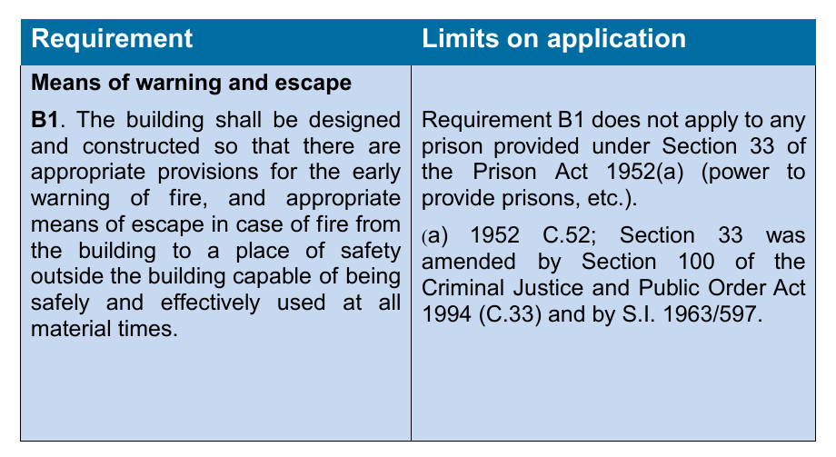
This Approved Document deals with the following Requirement from Part B of Schedule 1 to the Building Regulations 2010.
Requirement
Means of warning and escape
Guidance B1
#Source page 21
Contents > Use of guidance > General introduction > Means of warning > Section 1 | 2 | 3 | 4 | 5 | 6 | 7 | 8 | 9 | 10 | 11 | 12 > Appendix A | B | C | D | E | F | G > Publications > Index
Means of warning
Guidance B1
Performance
In the Welsh Ministers’ view the Requirement B1 will be met if:
a.there is sufficient means for giving early warning of fire for persons in the building;
b.there are routes of sufficient number and capacity, which are suitably located to enable persons to escape to a place of safety in the event of fire; and
c.the routes are sufficiently protected from the effects of fire, where necessary.
Introduction
B1.i These provisions relate to building work and material changes of use which are subject to the functional requirement B1; they may therefore affect new or existing buildings. They are concerned with the measures necessary to ensure reasonable facilities for means of warning and escape in case of fire. They are only concerned with fire precautions where these are necessary to safeguard escape routes.
They assume that in the design of the building, reliance should not be placed on external rescue by the fire and rescue service nor should it be based on a presumption that they will attend an incident within a given time. This Approved Document has been prepared on the basis that, in an emergency, the occupants of any part of a building should be able to escape safely without any external assistance.
It should also be noted that the guidance for a typical one or two storey dwellinghouse is limited to the provision of an automatic fire suppression system, smoke alarms and to the provision of openable windows for emergency egress.
Analysis of the problem
B1.ii The design of means of escape and the provision of other fire safety measures, such as smoke alarms, should be based on an assessment of the risk to the occupants in the event of fire. The assessment should take into account the nature of the building structure; the use of the building; the potential of fire spread through the building; and the standard of fire safety management proposed. Where it is not possible to identify with any certainty any of these elements, a judgement as to the likely level of provision must be made.
B1.iii Fires do not normally start in two different places in a building at the same time. Initially, a fire will create a hazard only in the part in which it starts and it is unlikely, at this stage, to involve a large area. The fire may
Page 22
#Source page 22
Contents > Use of guidance > General introduction > Means of warning > Section 1 | 2 | 3 | 4 | 5 | 6 | 7 | 8 | 9 | 10 | 11 | 12 > Appendix A | B | C | D | E | F | G > Publications > Index
Means of warning subsequently spread to other parts of the building, usually along the circulation routes. The items that are the first to be ignited are often furnishings and other items not controlled by the Building Regulations. It is less likely that the fire will originate in the structure of the building itself and the risk of it originating accidentally in circulation areas is limited, provided that the combustible content of such areas is restricted.
B1.iv The primary danger associated with fire in its early stages is not flame but the smoke and noxious gases produced by the fire. They cause most of the casualties and may also obscure the way to escape routes and exits. Measures designed to provide safe means of escape must therefore provide appropriate arrangements to limit the rapid spread of smoke and fumes.
Criteria for means of escape
B1.v The basic principles for the design of means of escape are:
a.that there should be alternative means of escape from most situations;
b.where direct escape to a place of safety is not possible, it should be possible to reach a place of relative safety, such as a protected stairway, which is on a route to an exit, within a reasonable travel distance; and
c.in certain conditions, a single direction of escape (a dead end) can be accepted as providing reasonable safety. These conditions depend on the use of the building and its associated fire risk, the size and height of the building, the extent of the dead end and the numbers of persons accommodated within the dead end.
The ultimate place of safety is the open air clear of the effects of the fire.
B1.vi For the purposes of Building Regulations, the following are not acceptable as means of escape:
a.lifts (except for a suitably designed and installed evacuation lift);
b.portable ladders and throw-out ladders; and
c.manipulative apparatus and appliances, e.g. fold-down ladders and chutes.
Note: The regulations would not prohibit the use of such measures as an additional feature but they are not considered suitable as an alternative to adequate means of escape.
Unprotected and protected escape routes
B1.vii The unprotected part of an escape route is that part which a person has to traverse before reaching either the safety of a final exit or the
Page 23
#Source page 23
Contents > Use of guidance > General introduction > Means of warning > Section 1 | 2 | 3 | 4 | 5 | 6 | 7 | 8 | 9 | 10 | 11 | 12 > Appendix A | B | C | D | E | F | G > Publications > Index
Means of warning comparative safety of a protected escape route, i.e. a protected corridor or protected stairway.
Unprotected escape routes should be limited in extent so that people do not have to travel excessive distances while exposed to the immediate danger of fire and smoke.
Even with protected horizontal escape routes the distance to a final exit or protected stairway needs to be limited because the structure does not give protection indefinitely.
B1.viiiProtected stairways are designed to provide virtually ‘fire sterile’ areas which lead to places of safety outside the building. Once inside a protected stairway, a person can be considered to be safe from immediate danger from flame and smoke. They can then proceed to a place of safety at their own pace. To enable this to be done, flames, smoke and gases must be excluded from these escape routes, as far as is reasonably possible, by fire-resisting construction and doors or by an appropriate smoke control system, or by a combination of both of these methods.
Security B1.ix The need for easy and rapid evacuation of a building in case of fire may conflict with the control of entry and exit in the interest of security. Measures intended to prevent unauthorised access can also hinder entry of the fire and rescue service to rescue people trapped by fire.
Potential conflicts should be identified and resolved at the design stage and not left until after completion of the work. The architectural liaison officers attached to most police forces are a valuable source of advice.
This document does not intend for the types of lock used on windows (see paragraph 3.8) and entrance doors to dwellinghouses to be controlled under the Building Regulations.
General
Use of the document
B1.x Section 1 deals with fire detection and alarm systems. Section 2 deals with automatic fire suppression systems. Section 3 deals with means of escape.
Section 1 B1
#Source page 24
Contents > Use of guidance > General introduction > Means of warning > Section 1 | 2 | 3 | 4 | 5 | 6 | 7 | 8 | 9 | 10 | 11 | 12 > Appendix A | B | C | D | E | F | G > Publications > Index
Section 1
Section 1 B1
Fire detection and fire alarm systems
Introduction
1.1Provisions are made in this section for suitable arrangements to be made in dwellinghouses to give early warning in the event of fire.
General
1.2The installation of smoke alarms, or automatic fire detection and alarm systems can significantly increase the level of safety by automatically giving an early warning of fire. The following guidance is appropriate for most dwellinghouses. However, where it is known that the occupants of a proposed dwellinghouse are at a special risk from fire, it may be more appropriate to provide a higher standard of protection, e.g. additional detectors.
1.3All new dwellinghouses should be provided with a fire detection and fire alarm system in accordance with the relevant recommendations of BS 5839-6:2004 to at least a Grade D Category LD3 standard.
1.4The smoke and heat alarms should be mains-operated and conform to BS EN 14604:2005, Smoke alarm devices or BS 5446-2:2003, Fire detection and fire alarm devices for dwellinghouses, Part 2 Specification for heat alarms, respectively. They should have a standby power supply, such as a battery (either rechargeable or non-rechargeable) or capacitor. More information on power supplies is given in clause 15 of BS 5839-6:2004.
Note: BS EN 14604 covers smoke alarms based on ionization chamber smoke detectors and optical (photo-electric) smoke detectors. The different types of detector respond differently to smoldering and fast-flaming fires. Either type of detector is generally suitable. However, the choice of detector type should, if possible, take into account the type of fire that might be expected and the need to avoid false alarms. Optical detectors tend to be less affected by low levels of ‘invisible’ particles, such as fumes from kitchens that often cause false alarms. Accordingly, they are generally more suitable than ionization chamber detectors for installation in circulation spaces adjacent to kitchens.
Large houses
1.5A dwellinghouse is regarded as large if it has more than one storey and any of those storeys exceed 200m2.
1.6A large dwellinghouse of 2 storeys (excluding basement storeys) should be fitted with a fire detection and fire alarm system of Grade B category LD3 as described in BS 5839-6:2004.
Page 25
#Source page 25
Contents > Use of guidance > General introduction > Means of warning > Section 1 | 2 | 3 | 4 | 5 | 6 | 7 | 8 | 9 | 10 | 11 | 12 > Appendix A | B | C | D | E | F | G > Publications > Index
Section 1
1.7A large dwellinghouse of 3 or more storeys (excluding basement storeys) should be fitted with a Grade A Category LD2 system as described in BS 5839-6:2004, with detectors sited in accordance with the recommendations of BS 5839- 1:2002 for a Category L2 system.
Material alterations
1.8Where new habitable rooms are provided above the ground floor level, or where they are provided at ground floor level and there is no final exit from the new room, a fire detection and fire alarm system should be installed. Smoke alarms should be provided in the circulation spaces of the dwellinghouse in accordance with paragraphs 1.10 to 1.18 to ensure that any occupants of the new rooms are warned of any fire that may impede their escape.
Sheltered housing
1.9The detection equipment in a sheltered housing scheme with a warden or supervisor should have a connection to a central monitoring point (or alarm receiving centre) so that the person in charge is aware that a fire has been detected in one of the dwellinghouses and can identify the dwellinghouse concerned. These provisions are not intended to be applied to the common parts of a sheltered housing development, such as communal lounges, or to sheltered accommodation in the Institutional or Other residential purpose groups (see Approved Document B Volume 2).
Positioning of smoke and heat alarms
1.10Detailed guidance on the design and installation of fire detection and alarm systems in dwellinghouses is given in BS 5839-6:2004. However, the following guidance is appropriate to most common situations.
1.11Smoke alarms should normally be positioned in the circulation spaces between sleeping spaces and places where fires are most likely to start (e.g. kitchens and living rooms) to pick up smoke in the early stages of a fire.
1.12There should be at least one smoke alarm on every storey of a dwellinghouse.
1.13Where the kitchen area is not separated from the stairway or circulation space by a door, there should be a compatible interlinked heat detector or heat alarm in the kitchen, in addition to whatever smoke alarms are needed in the circulation space(s).
1.14Where more than one alarm is installed they should be linked so that the detection of smoke or heat by one unit operates the alarm signal in all of them. The manufacturers’ instructions about the maximum number of units that can be linked should be observed.
1.15Smoke alarms/detectors should be sited so that:
Page 26
#Source page 26
Contents > Use of guidance > General introduction > Means of warning > Section 1 | 2 | 3 | 4 | 5 | 6 | 7 | 8 | 9 | 10 | 11 | 12 > Appendix A | B | C | D | E | F | G > Publications > Index
Section 1
a.there is a smoke alarm in the circulation space within 7.5m of the door to every habitable room;
b.they are ceiling-mounted and at least 300mm from walls and light fittings (unless, in the case of light fittings, there is test evidence to prove that the proximity of the light fitting will not adversely affect the efficiency of the detector). Units designed for wall-mounting may also be used provided that the units are above the level of doorways opening into the space and they are fixed in accordance with manufacturers’ instructions; and
c.the sensor in ceiling-mounted devices is between 25mm and 600mm below the ceiling (25-150mm in the case of heat detectors or heat alarms).
Note: This guidance applies to ceilings that are predominantly flat and horizontal.
1.16It should be possible to reach the smoke alarms to carry out routine maintenance, such as testing and cleaning, easily and safely. For this reason smoke alarms should not be fixed over a stair or any other opening between floors.
1.17Smoke alarms should not be fixed next to or directly above heaters or air- conditioning outlets. They should not be fixed in bathrooms, showers, cooking areas or garages, or any other place where steam, condensation or fumes could give false alarms.
1.18Smoke alarms should not be fitted in places that get very hot (such as a boiler room) or very cold (such as an unheated porch). They should not be fixed to surfaces which are normally much warmer or colder than the rest of the space, because the temperature difference might create air currents which move smoke away from the unit.
Power supplies
1.19The power supply for a smoke alarm system should be derived from the dwellinghouse’s mains electricity supply. The mains supply to the smoke alarm(s) should comprise a single independent circuit at the dwellinghouse’s main distribution board (consumer unit) or a single regularly used local lighting circuit. This has the advantage that the circuit is unlikely to be disconnected for any prolonged period. There should be a means of isolating power to the smoke alarms without isolating the lighting.
1.20The electrical installation should comply with Approved Document P (Electrical safety).
1.21Any cable suitable for domestic wiring may be used for the power supply and interconnection to smoke alarm systems. It does not need any particular fire survival properties except in large houses (BS 5839-6:2004 specifies fire resisting cables for Grade A and B systems). Any conductors used for interconnecting alarms (signalling) should be readily distinguishable from those supplying mains power, e.g. by colour coding.
Design and installation of systems
#Source page 27
Contents > Use of guidance > General introduction > Means of warning > Section 1 | 2 | 3 | 4 | 5 | 6 | 7 | 8 | 9 | 10 | 11 | 12 > Appendix A | B | C | D | E | F | G > Publications > Index
Section 1
Note: Mains-powered smoke alarms may be interconnected using radio-links, provided that this does not reduce the lifetime or duration of any standby power supply below 72 hours. In this case, the smoke alarms may be connected to separate power circuits (see paragraph 1.19).
1.22Other effective options exist and are described in BS 5839-1:2002 and BS 5839- 6:2004. For example, the mains supply may be reduced to extra low voltage in a control unit incorporating a standby trickle-charged battery, before being distributed at that voltage to the alarms.
Design and installation of systems
1.23It is essential that fire detection and fire alarm systems are properly designed, installed and maintained. Where a fire alarm system is installed, an installation and commissioning certificate should be provided. Third party certification schemes for fire protection products and related services are an effective means of providing the fullest possible assurances, offering a level of quality, reliability and safety.
1.24A requirement for maintenance cannot be made as a condition of passing plans by the Building Control Body. However, the attention of developers and builders is drawn to the importance of providing the occupants with information on the use of the equipment, and on its maintenance (or guidance on suitable maintenance contractors). See paragraph 0.11.
Note: BS 5839-1 and BS 5839-6 recommend that occupiers should receive the manufacturers’ instructions concerning the operation and maintenance of the alarm system.
Section 1
#Source page 28
9| 10 | 11 | 12 > Appendix A | B | C | D | E | F | G > Publications > Index
Section 1
Regulation 37A and 37B states:
Provision of automatic fire suppression systems 37A.—(1) This regulation applies where building work consists of the erection or material change of use of a building in relation to—
(a)care homes as defined, means places at which a care home service, within the meaning of Part 1 of the Regulation and Inspection of Social Care (Wales) Act 2016, is provided wholly or mainly to persons aged 18 or over;
(b)rooms for residential purposes other than rooms in—
(i)a hostel providing temporary accommodation to those who are ordinarily resident elsewhere;
(ii)an hotel;
(iii)a prison or young offender institution; and
(iv)a hospital
(c)dwelling-houses and flats, subject to paragraphs (4) and (5).
(2)For the purposes of this regulation a material change of use comprises or includes a change of use within regulation 5 (a), (b), (c), (d), (g), (h) or (i).
(3)A building to which this regulation applies must be provided with an automatic fire suppression system which is installed and operates in accordance with the requirements set in regulation 37B.
(4)This regulation does not apply to buildings which are—
(a)listed in accordance with section 1 of the Planning (Listed Buildings and Conservation Areas) Act 1990;
(b)in a conservation area designated in accordance with section 69 of that Act; or
(c)included in the schedule of monuments maintained under section 1 of the Ancient Monuments and Archaeological Areas Act 1979,
where installation of a fire suppression system would unacceptably alter their character or appearance.
(5)This regulation does not apply to temporary buildings with a planned time of use of two years or less.
Requirements of automatic fire suppression systems
37B.For the purposes of regulation 37A(3), the requirements of an automatic fire suppression system are the requirements set out in any document approved and issued under section 6 of the Building Act 1984 for the purpose of providing practical guidance as to the requirements of regulation 37A.”
Section 2 B1
#Source page 29
Section 2
Section 2 B1
Residential automatic fire suppression systems
Introduction
2.1Automatic fire suppression systems installed in dwellinghouses can reduce the risk to life and significantly reduce the degree of damage caused by fire. Protection b y a utomatic fire suppression systems can also sometimes be used as a compensatory feature where the provisions of this Approved Document are varied in some way.
2.2Regulation 37A brings in a mandatory requirement for automatic fire suppression systems in all new premises of Purpose Groups 1a, 1b, 1c, 2a and 2b constructed in Wales with the exception of hospitals, hotels, prisons, and a hostel providing temporary accommodation to those who are ordinarily resident elsewhere.
General
2.3Where an automatic fire suppression systems is required or recommended within this document it should be a system which is, designed and installed in accordance with an appropriate, fully implemented, technical standard such as BS 9251: 2014 Sprinkler systems for domestic and residential occupancies - Code of practice or an equivalent technical standard.
The components of the automatic fire suppression systems should be in accordance with an appropriate, fully implemented, technical standard such as BS 9252: 2011 Components for residential sprinkler systems – Specification and test methods for residential sprinklers or an equivalent technical standard.
Where an alternative technical standard (to BS 9251 or BS 9252) is used the guidance of Section 2.5 and Appendix A should be followed.
2.4Where an automatic fire suppression system is provided, it is normal practice to provide protection throughout the building to cover all areas required by the relevant technical standard. However, where the automatic fire suppression system is being installed as a compensatory feature to address a specific risk or hazard it may be acceptable to protect only part of a building.
Further guidance can also be found in Sprinklers for Safety: Use and Benefits of Incorporating Sprinklers in Buildings and Structures, BAFSA (2006) ISBN: 0 95526 280 1.
Page 30
#Source page 30
Section 2
2.5There are many alternative or innovative fire suppression systems available. Where these are used it is necessary to ensure that such systems have been designed and tested for use in domestic buildings and are fit for their intended purpose.
Installation
2.6The recommendations of Section 1.23 also apply to residential automatic fire suppression systems. It is essential that automatic fire suppression systems are properly designed, installed and maintained. Where an automatic fire suppression system is installed, an installation and commissioning certificate should be provided. Third party certification schemes for fire protection products and related services are an effective means of providing the fullest possible assurances, offering a level of quality, reliability and safety.
2.7For the purposes of meeting the requirements of Regulation 37A:
a.Where town mains are to be used, the designer must consult with the Water Undertaker to establish the typical operating water pressure range and flow capacities available.
b.Where town mains are to be used restrictions such as water meters shall not reduce the pressure and flow available below the performance specification detailed in the relevant technical standard.
c.Ancillary areas (such as car port, car park, garage etc.) which are normally unoccupied do not require an automatic fire suppression system if they are suitably fire separated from the residential areas (See Tables A1 and A2). The minimum acceptable separation is 30 minutes integrity, insulation and stability.
Alternative designs for means of escape
2.8The guidance in Section 3 for means of escape deals with some common arrangements of residential buildings. Other, less common, arrangements (for example residences entered above or below accommodation level, or residences containing galleries or open plan layouts) are also acceptable where automatic fire suppression is provided. Guidance on these is given in BS9991: 2011 and The NHBC and BRE Open Plan Flat Layouts: Assessing life safety in the event of fire.
Material Alterations
2.9Where an existing dwellinghouse is not currently provided with an automatic fire suppression system and a material alteration is undertaken, then the introduction of a suppression system to the new or existing areas of the building would not be required. However, there will be some cases where the material alteration would result in significant changes to the existing means of escape strategy for the building or residence. Where this occurs an automatic fire suppression system may be required if the material alteration results in the fire safety provisions being less satisfactory than previously. This should be determined on a case by case basis. Reference should be made to paragraph 0.17 .
Section 3 B1
#Source page 31
Contents > Use of guidance > General introduction > Means of warning > Section 1 | 2 | 3 | 4 | 5 | 6 | 7 | 8 | 9 | 10 | 11 | 12 > Appendix A | B | C | D | E | F | G > Publications > Index
Section 3
Section 3 B1
Means of escape
Introduction
3.1The means of escape from a typical one or two storey dwellinghouse is relatively simple to provide. Few provisions are specified in this document beyond ensuring that means are provided for giving early warning in the event of fire (see Section 1), automatic fire suppression is provided (see Section 2) and that suitable means are provided for emergency egress from each storey via windows or doors.
With increasing height more complex provisions are needed because emergency egress through upper windows becomes increasingly hazardous. For floors above 4.5m above ground level, it is then necessary to protect the internal stairway or provide alternative means of escape. See Diagram 1.
Note: Ground level is explained in Appendix C, Diagram C1.
3.2In providing any kind of fire protection in houses it should be recognised that measures which significantly interfere with the day-to-day convenience of the occupants may be less reliable in the long term.
Provisions for escape from the ground storey
3.3Except for kitchens, all habitable rooms in the ground storey should either:
a.open directly onto a hall leading to the entrance or other suitable exit; or
b.be provided with a window (or door) which complies with paragraph 3.8.
Note: See also General Provisions.
Provisions for escape from upper floors not more than 4.5m above ground level
3.4Except for kitchens, all habitable rooms in the upper storey(s) of a dwellinghouse served by only one stair should be provided with:
a.a window (or external door) which complies with paragraph 3.8; or
b.direct access to a protected stairway (as described in 3.6 (a) or (b)).
Note: A single window can be accepted to serve two rooms provided both rooms have their own access to the stairs. A communicating door between the rooms should also be provided so that it is possible to gain access to the window without passing through the stair enclosure.
Note: See also General Provisions.
Page 32
#Source page 32
Contents > Use of guidance > General introduction > Means of warning > Section 1 | 2 | 3 | 4 | 5 | 6 | 7 | 8 | 9 | 10 | 11 | 12 > Appendix A | B | C | D | E | F | G > Publications > Index
Section 3
Provisions for escape from upper floors more than 4.5m above ground level
3.5The provisions described in 3.6 and 3.7 need not be followed if the dwellinghouse has more than one internal stairway, which afford effective alternative means of escape and are physically separated from each other.
Note: The necessary degree of separation is a matter of judgement, e.g. stairs may be separated by fire-resisting construction or by a number of rooms.
Dwellinghouses with one floor more than 4.5m above ground level
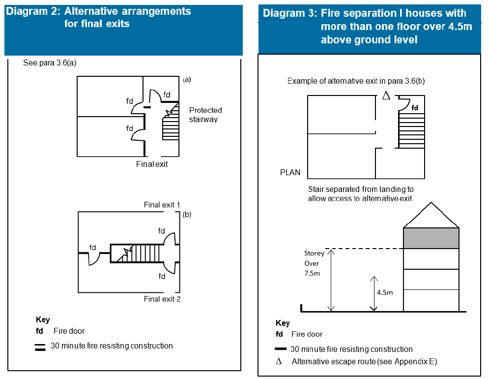
3.6The dwellinghouse may either have a protected stairway as described in (a) below, or the top floor can be separated and given its own alternative escape route as described in (b).
a.The upper storeys (those above ground storey) should be served by a protected stairway (protected at all levels) which should either:
i.extend to a final exit, see Diagram 2(a); or
ii.give access to at least two escape routes at ground level, each delivering to final exits and separated from each other by fire-resisting construction and fire doors, see Diagram 2(b); or
b.The top storey should be separated from the lower storeys by fire-resisting construction and be provided with an alternative escape route leading to its own final exit. See Diagram 3.
Note: See also General Provisions.
Dwellinghouses with more than one floor over 4.5m above ground level
3.7Where a dwellinghouse has two or more storeys with floors more than 4.5m above ground level (typically a dwellinghouse of four or more storeys) then, in addition to meeting the provisions in paragraph 3.6:
a.an alternative escape route should be provided from each storey or level situated 7.5m or more above ground level; or
b.each storey or level situated 7.5m or more above ground level should be served by a protected stairway (protected at all levels) as per paragraph 3.6a.
Notes: See also General Provisions. If additional floors/storeys are being installed as material alteration to an existing dwellinghouse which is not provided with an automatic fire suppression system see paragraph 3.20.
Page 33
#Source page 33
Contents > Use of guidance > General introduction > Means of warning > Section 1 | 2 | 3 | 4 | 5 | 6 | 7 | 8 | 9 | 10 | 11 | 12 > Appendix A | B | C | D | E | F | G > Publications > Index
Section 3
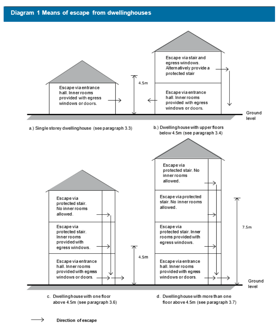
Notes: 1) This diagram must be read in conjunction with all of the relevant guidance given in Section 3
2) All new residential and domestic premises in Wales shall be provided with automatic fire suppression (see Section 2)
General provisions
#Source page 34
Contents > Use of guidance > General introduction > Means of warning > Section 1 | 2 | 3 | 4 | 5 | 6 | 7 | 8 | 9 | 10 | 11 | 12 > Appendix A | B | C | D | E | F | G > Publications > Index
Section 3
General provisions
Emergency egress windows and external doors
3.8Any window provided for emergency egress purposes and any external door provided for escape should comply with the following conditions:
a.the window should have an unobstructed openable area that is at least 0.33m2 and at least 450mm high and 450mm wide (the route through the window may be at an angle rather than straight through). The bottom of the openable area should be not more than 1100mm above the floor; and
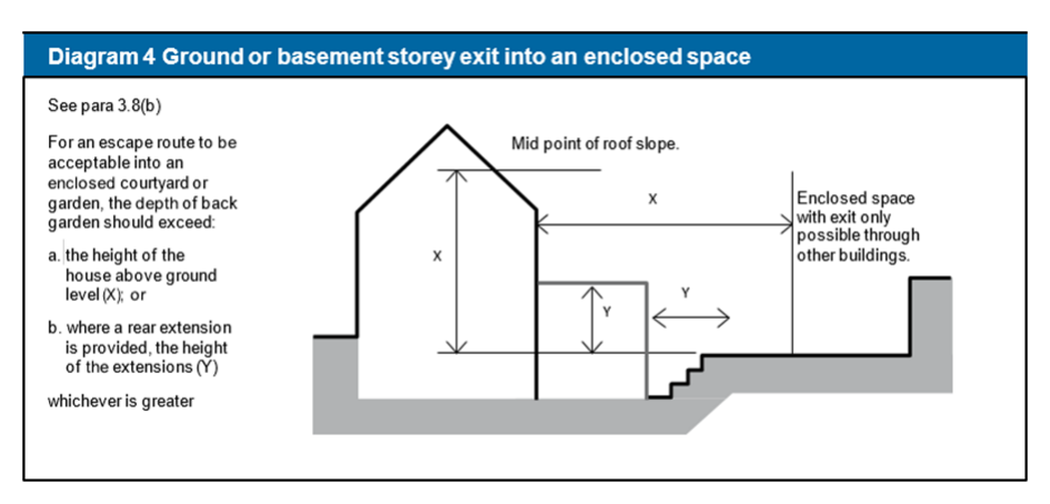
b.the window or door should enable the person escaping to reach a place free from danger from fire. This is a matter for judgement in each case, but, in general, a courtyard or back garden from which there is no exit other than through other buildings would have to be at least as deep as the dwellinghouse is high to be acceptable, see Diagram 4.
Page 35
#Source page 35
Contents > Use of guidance > General introduction > Means of warning > Section 1 | 2 | 3 | 4 | 5 | 6 | 7 | 8 | 9 | 10 | 11 | 12 > Appendix A | B | C | D | E | F | G > Publications > Index
Section 3
Note 1: Approved Document K Protection from falling, collision and impact specifies a minimum guarding height of 800mm, except in the case of a window in a roof where the bottom of the opening may be 600mm above the floor.
Note 2: Locks (with or without removable keys) and stays may be fitted to egress windows, subject to the stay being fitted with a release catch, which may be child resistant.
Note 3: Windows should be designed such that they will remain in the open position without needing to be held by a person making their escape.
Page 36
#Source page 36
Contents > Use of guidance > General introduction > Means of warning > Section 1 | 2 | 3 | 4 | 5 | 6 | 7 | 8 | 9 | 10 | 11 | 12 > Appendix A | B | C | D | E | F | G > Publications > Index
Section 3
Inner rooms
3.9A room whose only escape route is through another room is termed an inner room and is at risk if a fire starts in that other room (access room). This situation may arise with open-plan layouts and galleries. Such an arrangement is only acceptable where the inner room is:
a.a kitchen;
b.a laundry or utility room;
c.a dressing room;
d.a bathroom, WC, or shower room;
e.any other room on a floor, not more than 4.5m above ground level, provided with an emergency egress window which complies with paragraph 3.8; or
f.a gallery which complies with paragraph 3.12.
Note: A room accessed only via an inner room (an inner-inner room) may be acceptable if it complies with the above, not more than one door separates the room from an interlinked smoke alarm and none of the access rooms is a kitchen.
Balconies and flat roofs
3.10A flat roof forming part of a means of escape should comply with the following provisions:
a.the roof should be part of the same building from which escape is being made;
b.the route across the roof should lead to a storey exit or external escape route; and
c.the part of the roof forming the escape route and its supporting structure, together with any opening within 3m of the escape route, should provide 30 minutes fire resistance (see Appendix A, Table A1).
3.11Where a balcony or flat roof is provided for escape purposes guarding may be needed, in which case it should meet the provisions in Approved Document K
Protection from falling, collision and impact.
Galleries
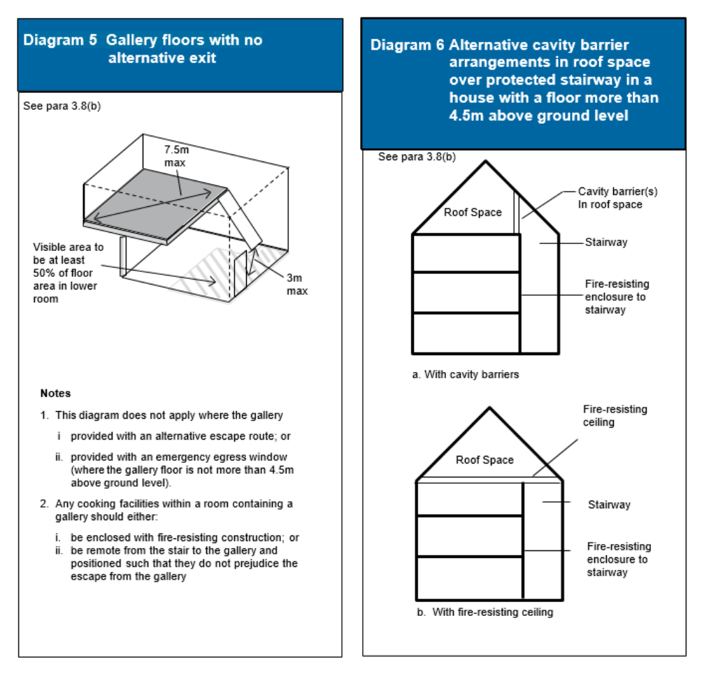
3.12A gallery should be provided with an alternative exit or, where the gallery floor is not more than 4.5m above ground level, an emergency egress window which complies with paragraph 3.8. Alternatively, where the gallery floor is not provided with an alternative exit or escape window, it should comply with the following;
a.the gallery should overlook at least 50% of the room below (see Diagram 5);
b.the distance between the foot of the access stair to the gallery and the door to the room containing the gallery should not exceed 3m;
c.the distance from the head of the access stair to any point on the gallery should not exceed 7.5m; and
Basements
#Source page 37
Contents > Use of guidance > General introduction > Means of warning > Section 1 | 2 | 3 | 4 | 5 | 6 | 7 | 8 | 9 | 10 | 11 | 12 > Appendix A | B | C | D | E | F | G > Publications > Index
Section 3 d. any cooking facilities within a room containing a gallery should either:
i. be enclosed with fire-resisting construction; or ii. be remote from the stair to the gallery and positioned such that they do not prejudice the escape from the gallery.
Basements
3.13Because of the risk that a single stairway may be blocked by smoke from a fire in the basement or ground storey, if the basement storey contains any habitable room, the dwellinghouse should be provided with either:
a.an external door or window suitable for egress from the basement (see paragraph 3.8); or
b.a protected stairway leading from the basement to a final exit.
Cavity barriers
3.14Cavity barriers should be provided above the enclosures to a protected stairway in a dwellinghouse with a floor more than 4.5m above ground level (see Diagram 6).
Page 38
#Source page 38
Contents > Use of guidance > General introduction > Means of warning > Section 1 | 2 | 3 | 4 | 5 | 6 | 7 | 8 | 9 | 10 | 11 | 12 > Appendix A | B | C | D | E | F | G > Publications > Index
External escape stairs
#Source page 39
Contents > Use of guidance > General introduction > Means of warning > Section 1 | 2 | 3 | 4 | 5 | 6 | 7 | 8 | 9 | 10 | 11 | 12 > Appendix A | B | C | D | E | F | G > Publications > Index
Section 3
External escape stairs
3.15Where an external escape stair is provided, it should meet the following provisions:
a.All doors giving access to the stair should be fire-resisting, except that a fire- resisting door is not required at the head of any stair leading downwards where there is only one exit from the building onto the top landing.
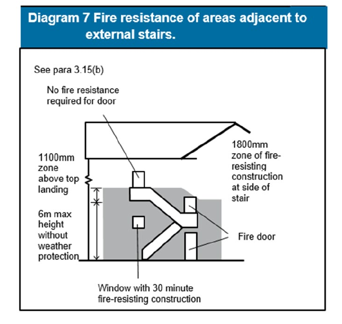
b.Any part of the external envelope of the building within 1800mm of (and 9m vertically below) the flights and landings of an external escape stair should be of fire-resisting construction, except that the 1800mm dimension may be reduced to 1100mm above the top level of the stair if it is not a stair up from a basement to ground level (see Diagram 7).
c.There is protection by fire-resisting construction for any part of the building (including any doors) within 1800mm of the escape route from the stair to a place of safety, unless there is a choice of routes from the foot of the stair that would enable the people escaping to avoid exposure to the effects of the fire in the adjoining building.
d.Any stair more than 6m in vertical extent is protected from the effects of adverse weather conditions. (This should not be taken to imply a full enclosure. Much will depend on the location of the stair and the degree of protection given to the stair by the building itself).
e.Glazing in areas of fire-resisting construction mentioned above should also be fire-resisting (integrity but not insulation) and fixed shut.
Page 40
#Source page 40
Contents > Use of guidance > General introduction > Means of warning > Section 1 | 2 | 3 | 4 | 5 | 6 | 7 | 8 | 9 | 10 | 11 | 12 > Appendix A | B | C | D | E | F | G > Publications > Index
Section 3
Air circulation systems in houses with a floor more than 4.5m above ground level
3.16Air circulation systems which circulate air within an individual dwellinghouse with a floor more than 4.5m above ground level should meet the guidance given in paragraph 3.17. Where ventilation ducts pass through compartment walls into another building then the guidance given in Approved Document B Volume 2 should be followed.
3.17With these types of systems, the following precautions are needed to avoid the possibility of the system allowing smoke or fire to spread into a protected stairway:
a.Transfer grilles should not be fitted in any wall, door, floor or ceiling enclosing a protected stairway.
b.Any duct passing through the enclosure to a protected stairway or entrance hall should be of rigid steel construction and all joints between the ductwork and the enclosure should be fire-stopped.
c.Ventilation ducts supplying or extracting air directly to or from a protected stairway, should not serve other areas as well.
d.Any system of mechanical ventilation which recirculates air and which serves both the stairway and other areas should be designed to shut down on the detection of smoke within the system.
e.A room thermostat for a ducted warm air heating system should be mounted in the living room, at a height between 1370mm and 1830mm, and its maximum setting should not exceed 27ºC.
Passenger lifts
3.18Where a passenger lift is provided in the dwellinghouse and it serves any floor more than 4.5m above ground level, it should either be located in the enclosure to the protected stairway (see paragraph 3.6) or be contained in a fire- resisting lift shaft.
Work on existing houses
Replacement windows
3.19Regulation 4(1) requires that all “building work”, as defined by Regulation 3, complies with the applicable requirements of Schedule 1 to the Building Regulations. The definition of building work in Regulation 3(1) includes the provision or extension of a “controlled service or fitting” in or in connection with a building. The definition of controlled service or fitting is given in Regulation 2(1), and includes a replacement window.
Where windows are to be replaced (but not where they are to be repaired only, as repair work to windows does not fall within the definition of building work) the replacement work should comply with the requirements of Parts L and N of Schedule 1. In addition, the building should not have a lesser level of compliance, after the work has been completed, with other applicable Parts of Schedule 1. For the purposes of Part B1, where a window is located such that, in a new dwellinghouse, an escape window would be necessary and the window is of sufficient size that it could be used for the purposes of escape then:
Page 41
#Source page 41
Contents > Use of guidance > General introduction > Means of warning > Section 1 | 2 | 3 | 4 | 5 | 6 | 7 | 8 | 9 | 10 | 11 | 12 > Appendix A | B | C | D | E | F | G > Publications > Index
Section 3
a.the replacement window opening should be sized to provide at least the same potential for escape as the window it replaces; or
b.where the original window is larger than necessary for the purposes of escape, the window opening could be reduced down to the minimum specified in paragraph 3.8.
Note: Part B3 makes provisions for cavity barriers around window openings in some forms of construction. Where windows are replaced it may be necessary to consider if adequate protection is maintained.
Material alterations
3.20Paragraph 0.17 sets out the requirements relating to material alterations. What constitutes reasonable provision where undertaking material alterations would depend on the circumstances in the particular case and would need to take account of historic value (see paragraph 0.26). Possible ways of satisfying the requirements include:
a. Smoke alarms
Where new habitable rooms are provided then smoke alarms should be provided in accordance with paragraph 1.8.
b. Loft conversions
Where a new storey is to be added by converting an existing roof space, the provisions for escape need to be considered throughout the full extent of the escape route. For example, a loft conversion to a two-storey house will result in the need to protect the stairway (by providing fire-resisting doors and partitions) where previously no protection may have existed (see paragraph 3.6a).
Note: If it is considered undesirable to replace existing doors (e.g. if they are of historical or architectural merit) it may be possible to retain the doors or upgrade them to an acceptable standard.
Note: Where an ‘open-plan’ arrangement exists at ground level it may be necessary to provide a new partition to enclose the escape route (see Diagram 2).
Alternatively, it may be possible to provide protection to the open-plan area using automatic fire suppression in conjunction with a fire-resisting partition and door (E20), in order to separate the ground floor from the upper storeys. This door should be so arranged to allow the occupants of the loft room to access an escape window at first floor level (in accordance with paragraph 3.8) in the event of a fire in the open-plan area. Cooking facilities should be separated from the open-plan area with fire-resisting construction.
c. Automatic fire suppression systems
Where an existing dwellinghouse is already provided with an automatic fire suppression system, the building as a whole should be no less compliant after a material alteration or building works occur. The automatic fire suppression system should be extended and re-certified to include any altered, extended and additional controlled areas. Further information is available in paragraph
0.17and section 2.
Page 42
#Source page 42
Contents > Use of guidance > General introduction > Means of warning > Section 1 | 2 | 3 | 4 | 5 | 6 | 7 | 8 | 9 | 10 | 11 | 12 > Appendix A | B | C | D | E | F | G > Publications > Index
Section 3 d. Alterations to form one floor more than 4.5m above ground level Where an existing dwellinghouse is not already provided with an automatic fire suppression system and is altered to have one storey more than 4.5m above ground level, then the guidance in paragraph 3.6 and if applicable 3.20b should be followed.
e. Alterations to form more than one floor over 4.5m above ground level Where an existing dwellinghouse is not already provided with an automatic fire suppression system and is altered to have two or more storeys with floors more than 4.5m above ground level (typically a dwellinghouse of four or more storeys) then, in addition to meeting the provisions in paragraph 3.6:
1.an alternative escape route should be provided from each storey or level situated 7.5m or more above ground level. Where the access to the alternative escape route is via:
i. the protected stairway to an upper storey; or ii. a landing within the protected stairway enclosure to an alternative escape route on the same storey; then iii. the protected stairway at or about 7.5m above ground level should be separated from the lower storeys or levels by fire- resisting construction, see Diagram 3; or
2.to provide a protected stairway plus an automatic fire suppression system in accordance with Section 2 (smoke alarms should also be provided in accordance with paragraph 1.9).
Internal Fire Spread (Lining) B2 The Requirement
#Source page 43
9| 10 | 11 | 12 > Appendix A | B | C | D | E | F | G > Publications > Index
Section 3
Internal Fire Spread (Lining) B2 The Requirement
Requirement Limits on application
| Internal fire spread (linings) B2. (1) To inhibit the spread of fire within the building, the internal linings shall: (a) adequately resist the spread of flame over their surfaces; and (b) have, if ignited, a rate of heat release or a rate of fire growth, which is reasonable in the circumstances. (2) In this paragraph ‘internal linings’ mean the materials or products used in lining any partition, wall, ceiling or other internal structure. |
Guidance B2
#Source page 44
Contents > Use of guidance > General introduction > Means of warning > Section 1 | 2 | 3 | 4 | 5 | 6 | 7 | 8 | 9 | 10 | 11 | 12 > Appendix A | B | C | D | E | F | G > Publications > Index
Section 3
Guidance B2
Performance
In the Welsh Ministers’ view the Requirements of B2 will be met if the spread of flame over the internal linings of the building is restricted by making provision for them to have low rates of surface spread of flame and, in some cases, to have a low rate of heat release, so as to limit the contribution that the fabric of the building makes to fire growth. In relation to the European fire tests and classification system, the requirements of B2 will be met if the heat released from the internal linings is restricted by making provision for them to have a resistance to ignition and a rate of fire growth which are reasonable in the circumstances.
The extent to which this is necessary is dependent on the location of the lining.
Introduction
Fire spread and internal linings
B2.i The choice of materials for walls and ceilings can significantly affect the spread of a fire and its rate of growth, even though they are not likely to be the materials first ignited.
It is particularly important in circulation spaces where linings may offer the main means by which fire spreads and where rapid spread is most likely to prevent occupants from escaping.
Several properties of lining materials influence fire spread. These include the ease of ignition and the rate at which the lining material gives off heat when burning. The guidance relating to the European fire tests and classification provides for control of internal fire spread through control of these properties. This document does not give detailed guidance on other properties, such as the generation of smoke and fumes.
Floors and stairs
B2.ii The provisions do not apply to the upper surfaces of floors and stairs because they are not significantly involved in a fire until it is well developed, and thus do not play an important part in fire spread in the early stages of a fire that are most relevant to the safety of occupants.
Other controls on internal surface properties
B2.iii In Section 8 there is guidance on enclosures to above ground drainage system pipes.
Note: External flame spread is dealt with in Sections 9 to 11.
Furniture and fittings
B2.iv Furniture and fittings can have a major effect on fire spread but it is not possible to control them through Building Regulations. They are therefore not dealt with in this Approved Document.
Page 45
#Source page 45
Contents > Use of guidance > General introduction > Means of warning > Section 1 | 2 | 3 | 4 | 5 | 6 | 7 | 8 | 9 | 10 | 11 | 12 > Appendix A | B | C | D | E | F | G > Publications > Index
Section 3
Classification of performance
B2.v Appendix A describes the different classes of performance and the appropriate methods of test (see paragraphs 13-23).
The national classifications used are based on tests in BS 476 Fire tests on building materials and structures, namely BS 476-6:1989 Method of test for fire propagation for products and BS 476-7:1997 Method of test to determine the classification of the surface spread of flame of products. However, BS 476-4:1970 Non-combustibility test for materials and BS 476-11:1982 Method for assessing the heat emission from building products are also used as one method of meeting Class 0. Other tests are available for classification of thermoplastic materials if they do not have the appropriate rating under BS 476: Part 7; three ratings, referred to as TP(a) rigid and TP(a) flexible and TP(b), are used.
The European classifications are described in BS EN 13501-1:2002 Fire classification of construction products and building elements, Part 1 Classification using data from reaction to fire tests. They are based on a combination of four European test methods, namely:
•BS EN ISO 1182:2002, Reaction to fire tests for building products – Non combustibility test.
•BS EN ISO 1716:2002, Reaction to fire tests for building products – Determination of the gross calorific value.
•BS EN 13823:2002, Reaction to fire tests for building products – Building products excluding floorings exposed to the thermal attack by a single burning item.
•BS EN ISO 11925-2:2002, Reaction to fire tests for building products, Part 2 Ignitability when subjected to direct impingement of flame.
For some building products, there is currently no generally accepted guidance on the appropriate procedure for testing and classification in accordance with the harmonised European fire tests. Until such a time that the appropriate European test and classification methods for these building products are published classification may only be possible using existing national test methods.
Table A8, in Appendix A, gives typical performance ratings which may be achieved by some generic materials and products.
Section 4 B2 Wall and ceiling linings
#Source page 46
9| 10 | 11 | 12 > Appendix A | B | C | D | E | F | G > Publications > Index Section 4
Section 4 B2 Wall and ceiling linings
Classification of linings 4.1 Subject to the variations and specific provisions described in paragraphs 4.2 to 4.16, the surface linings of walls and ceilings should meet the following classifications:
| Location | National class (1) | European class (1)(3)(4) |
|---|---|---|
| Small rooms(2) of area not more than 4m ² | 3 | D-s3, d2 |
| Domestic garages of area not more than 40m ² | ||
| Other rooms(2) (including garages) | 1 | C-s3, d2 |
| Circulation spaces within dwellinghouses |
Notes:
1.See paragraph B2.v.
2.For meaning of room, see definition in Appendix E.
3.The National classifications do not automatically equate with the equivalent classifications in the European column, therefore products cannot typically assume a European class, unless they have been tested accordingly.
4.When a classification includes ‘s3, d2’, this means that there is no limit set for smoke production and/or flaming droplets/particles.
Definition of walls
4.2For the purpose of the performance of wall linings, a wall includes:
a.the surface of glazing (except glazing in doors); and
b.any part of a ceiling which slopes at an angle of more than 70º to the horizontal.
Page 47
#Source page 47
Contents > Use of guidance > General introduction > Means of warning > Section 1 | 2 | 3 | 4 | 5 | 6 | 7 | 8 | 9 | 10 | 11 | 12 > Appendix A | B | C | D | E | F | G > Publications > Index
Section 4
But a wall does not include:
c.doors and door frames;
d.window frames and frames in which glazing is fitted;
e.architraves, cover moulds, picture rails, skirtings and similar narrow members; or
f.fireplace surrounds, mantle shelves and fitted furniture.
Definition of ceilings
4.3For the purposes of the performance of ceiling linings, a ceiling includes:
a.the surface of glazing;
b.any part of a wall which slopes at an angle of 70º or less to the horizontal;
c.the underside of a gallery; and
d.the underside of a roof exposed to the room below.
But a ceiling does not include:
e.trap doors and their frames;
f.the frames of windows or rooflights (see Appendix E) and frames in which glazing is fitted; or
g.architraves, cover moulds, picture rails, exposed beams and similar narrow members.
Variations and special provisions
Walls
4.4Parts of walls in rooms may be of a poorer performance than specified in paragraph 4.1 (but not poorer than Class 3 (National class) or Class D-s3, d2 (European class) provided the total area of those parts in any one room does not exceed one half of the floor area of the room, subject to a maximum of 20m2.
Fire-protecting suspended ceilings
4.5A suspended ceiling can contribute to the overall fire resistance of a floor/ceiling assembly. Such a ceiling should satisfy paragraph 4.1. It should also meet the provisions of Appendix A, Table A3.
Fire-resisting ceilings
4.6Cavity barriers are needed in some concealed floor or roof spaces (see Section 7), however, this need can be reduced by the use of a fire-resisting ceiling below the cavity.
Rooflights
4.7Rooflights should meet the relevant classification in 3.1. However, plastic rooflights with at least a Class 3 rating may be used where 3.1 calls for a higher standard, provided the limitations in Table 2 and in Table 6 are observed.
Note: No guidance is currently possible on the performance requirements in the European fire tests as there is no generally accepted test and classification procedure.
Page 48
#Source page 48
Contents > Use of guidance > General introduction > Means of warning > Section 1 | 2 | 3 | 4 | 5 | 6 | 7 | 8 | 9 | 10 | 11 | 12 > Appendix A | B | C | D | E | F | G > Publications > Index
Section 4
Thermoplastic materials
General
4.8Thermoplastic materials (see Appendix A, paragraphs 20-23) which cannot meet the performance given in Table 1, can nevertheless be used in windows, rooflights and lighting diffusers in suspended ceilings if they comply with the provisions described in paragraphs 4.10 to 4.14. Flexible thermoplastic material may be used in panels to form a suspended ceiling if it complies with the guidance in paragraph 4.16. The classifications used in paragraphs 4.11 to 4.16, Table 2 and Diagram 9 are explained in Appendix A, paragraph 23.
Note: No guidance is currently possible on the performance requirements in the European fire tests as there is no generally accepted test and classification procedure.
Windows and internal glazing
4.9External windows to rooms (though not to circulation spaces) may be glazed with thermoplastic materials, if the material can be classified as a TP(a) rigid product .
Internal glazing should meet the provisions in paragraph 4.1.
Notes:
1.A ‘wall’ does not include glazing in a door (see paragraph 4.2).
2.Attention is drawn to the guidance on the safety of glazing in Approved Document N
Glazing – safety in relation to impact, opening and cleaning.
Rooflights
4.10Rooflights to rooms and circulation spaces (with the exception of protected stairways) may be constructed of a thermoplastic material if:
a.the lower surface has a TP(a) (rigid) or TP(b) classification;
b.the size and disposition of the rooflights accords with the limits in Table 2 and with the guidance to B4 in Table 7.
Lighting diffusers
4.11The following provisions apply to lighting diffusers which form part of a ceiling. They are not concerned with diffusers of light fittings which are attached to the soffit of, or suspended beneath a ceiling (see Diagram 8).
Lighting diffusers are translucent or open- structured elements that allow light to pass through. They may be part of a luminaire or used below rooflights or other sources of light.
4.12Thermoplastic lighting diffusers should not be used in fire-protecting or fire- resisting ceilings, unless they have been satisfactorily tested as part of the ceiling system that is to be used to provide the appropriate fire protection.
4.13Subject to the above paragraphs, ceilings to rooms and circulation spaces (but not protected stairways) may incorporate thermoplastic lighting diffusers if the following provisions are observed:
Suspended or stretched-skin ceilings
#Source page 49
Contents > Use of guidance > General introduction > Means of warning > Section 1 | 2 | 3 | 4 | 5 | 6 | 7 | 8 | 9 | 10 | 11 | 12 > Appendix A | B | C | D | E | F | G > Publications > Index
Section 4
a.Wall and ceiling surfaces exposed within the space above the suspended ceiling (other than the upper surfaces of the thermoplastic panels) should comply with the general provisions of paragraph 4.1, according to the type of space below the suspended ceiling;
b.If the diffusers are of classification TP(a) (rigid), there are no restrictions on their extent;
c.If the diffusers are of classification TP(b), they should be limited in extent as indicated in Table 2 and Diagram 9.
Suspended or stretched-skin ceilings
4.14The ceiling of a room may be constructed either as a suspended or stretched-skin membrane from panels of a thermoplastic material of the TP(a) flexible classification, provided that it is not part of a fire-resisting ceiling. Each panel should not exceed 5m2 in area and should be supported on all its sides.
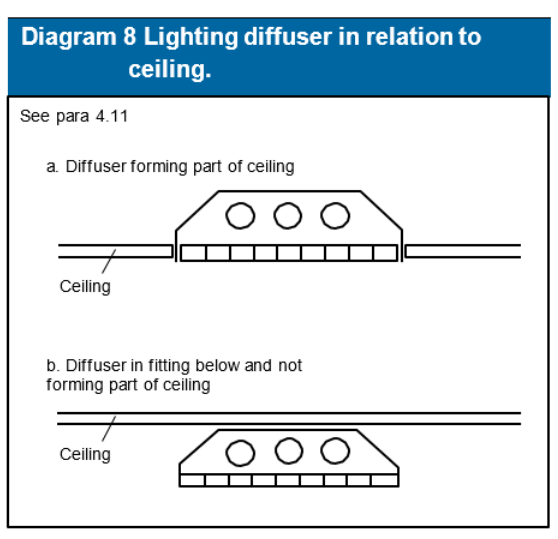
Section 4
#Source page 50
9| 10 | 11 | 12 > Appendix A | B | C | D | E | F | G > Publications > Index
Section 4
| Minimum classification of lower surface | Use of space below the diffusers or rooflight | Maximum area of each diffuser panel (1) or rooflight (m²) | Max total area of diffuser panels and rooflights as percentage of floor area of the space in which the ceiling is located (%) | Minimum separation distance between diffuser panels or (1) rooflights (m) |
|---|---|---|---|---|
| TP(a) | Any except protected stairway | (2) No limit | No limit | No limit |
| (3) Class 3 or TP(b) | Rooms | 5 | (4) 50 | 3 |
| Circulation spaces except protected stairways | 5 | (4) 15 | 3 |
Notes:
1.Smaller panels can be grouped together provided that the overall size of the group and the space between one group and any others satisfies the dimensions shown in Diagram 9.
2.Lighting diffusers of TP(a) flexible rating should be restricted to panels of not more than 5m² each, see paragraph 3.14.
3.There are no limits on Class 3 material in small rooms see Table 1.
4.The minimum 3m separation specified in Diagram 9 between each 5m² must be maintained. Therefore, in some cases it may not also be possible to use the maximum percentage quoted.
Page 51
#Source page 51
Contents > Use of guidance > General introduction > Means of warning > Section 1 | 2 | 3 | 4 | 5 | 6 | 7 | 8 | 9 | 10 | 11 | 12 > Appendix A | B | C | D | E | F | G > Publications > Index
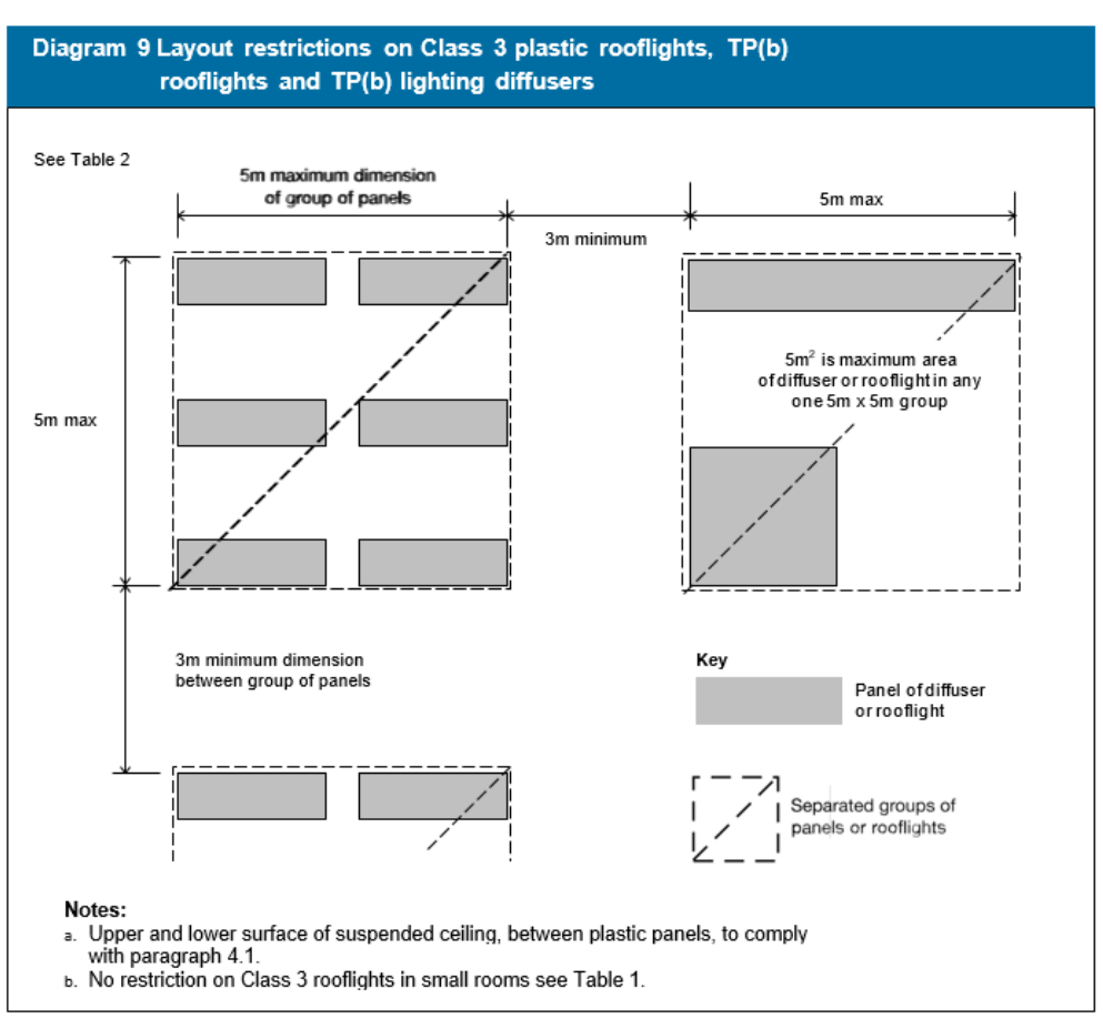
Internal Fire Spread (Structure) B3 The Requirement
#Source page 52
9| 10 | 11 | 12 > Appendix A | B | C | D | E | F | G > Publications > Index
Section 4
Internal Fire Spread (Structure) B3 The Requirement
This Approved Document deals with the following Requirement from Part B of Schedule 1 to the Building Regulations 2010.
Requirement Limits on application
| Internal fire spread (structure) B3. (1) The building shall be designed and constructed so that,in the event of fire,itsstability will be maintained for a reasonable period: (2) A wall common to two or more buildings shall be designed and constructed so that it adequately resists the spread of fire between those buildings. For the purposes of this sub- paragraph a house in a terrace and a semi-detached house are each to be treated as a separate building. (3) Where reasonably necessary to inhibit the spread of fire within the building, measures shall be taken, to an extent appropriate to the size and intended use of the building, comprising either or both of the following: (a) sub-division of the building with fire-resisting construction; (b) installation of suitable automatic fire suppression systems. (4) The building shall be designed and constructed so that the unseen spread of fire and smoke within concealed spaces in its structure and fabric is inhibited. | Requirement B3(3) does not apply to material alterations to any prison provided under Section 33 of the Prison Act 1952. (a) 1952 C.52; Section 33 was amended by Section 100 of the Criminal Justice and Public Order Act 1994 (C.33) and by S.I. 1963/597. |
Guidance B3
#Source page 53
Contents > Use of guidance > General introduction > Means of warning > Section 1 | 2 | 3 | 4 | 5 | 6 | 7 | 8 | 9 | 10 | 11 | 12 > Appendix A | B | C | D | E | F | G > Publications > Index
Section 4
Guidance B3
Performance
In the Welsh Ministers’ view the Requirements of B3 will be met:
a.if the loadbearing elements of structure of the building are capable of withstanding the effects of fire for an appropriate period without loss of stability;
b.if the building is sub-divided by elements of fire-resisting construction into compartments;
c.if any openings in fire-separating elements (see Appendix E) are suitably protected in order to maintain the integrity of the element (i.e. the continuity of the fire separation); and
d.if any hidden voids in the construction are sealed and sub-divided to inhibit the unseen spread of fire and products of combustion, in order to reduce the risk of structural failure and the spread of fire, in so far as they pose a threat to the safety of people in and around the building.
The extent to which any of these measures are necessary is dependent on the use of the building and, in some cases, its size, and on the location of the element of construction.
Introduction
B3.i Guidance on loadbearing elements of structure is given in Section 5. Section 6 is concerned with the sub-division of a building into compartments, and Section 7 makes provisions about concealed spaces (or cavities). Section 8 gives information on the protection of openings and on fire-stopping which relates to compartmentation and to fire spread in concealed spaces. Common to all these sections and to other provisions of Part B, is the property of fire resistance.
Fire resistance
B3.ii The fire resistance of an element of construction is a measure of its ability to withstand the effects of fire in one or more ways, as follows:
a.resistance to collapse, i.e. the ability to maintain loadbearing capacity (which applies to loadbearing elements only);
b.resistance to fire penetration, i.e. an ability to maintain the integrity of the element; and
c.resistance to the transfer of excessive heat, i.e. an ability to provide insulation from high temperatures.
B3.iii ‘Elements of structure’ is the term applied to the main structural loadbearing elements, such as structural frames, floors and loadbearing walls. Compartment walls are treated as elements of structure although they are not necessarily loadbearing. Roofs, unless they serve the function of a floor, are not treated as elements of structure. External walls, such as curtain walls or other forms of cladding which transmit only self weight and wind loads and do not transmit floor
Guidance elsewhere in the Approved Document concerning fire resistance
#Source page 54
Contents > Use of guidance > General introduction > Means of warning > Section 1 | 2 | 3 | 4 | 5 | 6 | 7 | 8 | 9 | 10 | 11 | 12 > Appendix A | B | C | D | E | F | G > Publications > Index
Section 4 load, are not regarded as loadbearing for the purposes of B3.ii(a), although they may need fire resistance to satisfy requirement B4 (see Sections 9 to10).
Loadbearing elements may or may not have a fire-separating function. Similarly, fire-separating elements may or may not be loadbearing.
Guidance elsewhere in the Approved Document concerning fire resistance
B3.iv There is guidance in Section 3 concerning the use of fire-resisting construction to protect means of escape. There is guidance in Section 10 about fire resistance of external walls to restrict the spread of fire between buildings. Appendix A gives information on methods of test and performance for elements of construction. Appendix B gives information on fire doors. Appendix C gives information on methods of measurement. Appendix D gives information on purpose group classification. Appendix E gives definitions.
Section 5 B3
#Source page 55
Contents > Use of guidance > General introduction > Means of warning > Section 1 | 2 | 3 | 4 | 5 | 6 | 7 | 8 | 9 | 10 | 11 | 12 > Appendix A | B | C | D | E | F | G > Publications > Index
Section 5
Section 5 B3
Loadbearing elements of structure
Introduction
5.1Premature failure of the structure can be prevented by provisions for loadbearing elements of structure to have a minimum standard of fire resistance, in terms of resistance to collapse or failure of loadbearing capacity. The purpose in providing the structure with fire resistance is threefold, namely:
a.to minimise the risk to the occupants, some of whom may be unable to make their own escape if they have become trapped or injured;
b.to reduce the risk to firefighters, who may be engaged in search or rescue operations; and
c.to reduce the danger to people in the vicinity of the building, who might be hurt by falling debris or as a result of the impact of the collapsing structure on other buildings.
Fire resistance standard
5.2Elements of structure such as structural frames, beams, columns, loadbearing walls (internal and external), floor structures and gallery structures should have at least the fire resistance given in Appendix A, Table A1.
Application of the fire resistance standards for loadbearing elements
5.3The measures set out in Appendix A include provisions to ensure that where one element of structure supports or gives stability to another element of structure, the supporting element has no less fire resistance than the other element (see notes to Table A2). The measures also provide for elements of structure that are common to more than one building or compartment, to be constructed to the standard of the greater of the relevant provisions. Special provisions about fire resistance of elements of structure in single storey buildings are also given and there are concessions in respect of fire resistance of elements of structure in basements where at least one side of the basement is open at ground level.
Exclusions from the provisions for elements of structure
5.4The following are excluded from the definition of element of structure for the purposes of these provisions:
a.structure that only supports a roof, unless:
i.the roof performs the function of a floor, such as a roof terrace, or as a means of escape (see Section 3), or
ii.the structure is essential for the stability of an external wall which needs to have fire resistance; and
b.the lowest floor of the building.
Page 56
#Source page 56
Contents > Use of guidance > General introduction > Means of warning > Section 1 | 2 | 3 | 4 | 5 | 6 | 7 | 8 | 9 | 10 | 11 | 12 > Appendix A | B | C | D | E | F | G > Publications > Index
Section 5
Additional guidance
5.5Guidance in other sections of this Approved Document may also apply if a loadbearing wall is:
a.a compartment wall (this includes a wall common to two buildings), (see Section 6);
b.a wall between a dwellinghouse and an integral garage, (see Section 6, paragraph 6.4);
c.protecting a means of escape, (see Section 3); or
d.an external wall, (see Sections 9 to10).
5.6If a floor is also a compartment floor, see Section 6.
Floors in loft conversions
5.7In altering an existing two-storey single family dwellinghouse to provide additional storeys, the provisions in this Approved Document are for the floor(s), both old and new, to have the full 30 minute standard of fire resistance shown in Appendix A, Table A1. However, provided that the following conditions are satisfied, namely:
a.only one storey is being added;
b.the new storey contains no more than 2 habitable rooms; and
c.the total area of the new storey does not amount to more than 50m2;
then the existing first floor construction may be accepted if it has at least a modified 30 minute standard of fire resistance, in those places where the floor separates only rooms (and not circulation spaces).
Notes:
1.The ‘modified 30 minute’ standard satisfies the test criteria for the full 30 minutes in respect of loadbearing capacity, but allows reduced performances for integrity and insulation (see Appendix A, Table A1, item 3(a)).
2.A floor which forms part of the enclosure to the circulation space between the loft conversion and the final exit needs a full 30 minute standard.
Conversion to flats
5.8Where an existing dwellinghouse or other building is converted into flats the guidance in Volume 2 should be followed.
Section 6 B3
#Source page 57
Contents > Use of guidance > General introduction > Means of warning > Section 1 | 2 | 3 | 4 | 5 | 6 | 7 | 8 | 9 | 10 | 11 | 12 > Appendix A | B | C | D | E | F | G > Publications > Index
Section 6
Section 6 B3
Compartmentation
Introduction
6.1The spread of fire within a building can be restricted by sub-dividing it into compartments separated from one another by walls and/or floors of fire-resisting construction. The object is twofold:
a.to prevent rapid fire spread which could trap occupants of the building; and
b.to reduce the chance of fires becoming large, on the basis that large fires are more dangerous, not only to occupants and fire and rescue service personnel, but also to people in the vicinity of the building. Compartmentation is complementary to provisions made in Section 3 for the protection of escape routes, and to provisions made in Sections 9 to 11 against the spread of fire between buildings.
Provision of compartmentation
6.2Compartment walls and compartment floors should be provided in the circumstances described below, with the proviso that the lowest floor in a building does not need to be constructed as a compartment floor. Provisions for the protection of openings in compartment walls and compartment floors are given in paragraph 6.13 and Section 8.
6.3Every wall separating semi-detached houses, or houses in terraces, should be constructed as a compartment wall and the houses should be considered as separate buildings.
6.4If a domestic garage is attached to (or forms an integral part of) a dwellinghouse, the garage should be separated from the rest of the dwellinghouse, as shown in Diagram 10.
6.5Where a door is provided between a dwellinghouse and the garage, the floor of the garage should be laid to fall to allow fuel spills to flow away from the door to the outside. Alternatively, the door opening should be positioned at least 100mm above garage floor level.
Construction of compartment walls and compartment floors
General
6.6Every compartment wall and compartment floor should:
a.form a complete barrier to fire between the compartments they separate; and
b.have the appropriate fire resistance as indicated in Appendix A, Tables A1 and A2.
Page 58
#Source page 58
Contents > Use of guidance > General introduction > Means of warning > Section 1 | 2 | 3 | 4 | 5 | 6 | 7 | 8 | 9 | 10 | 11 | 12 > Appendix A | B | C | D | E | F | G > Publications > Index
Section 6
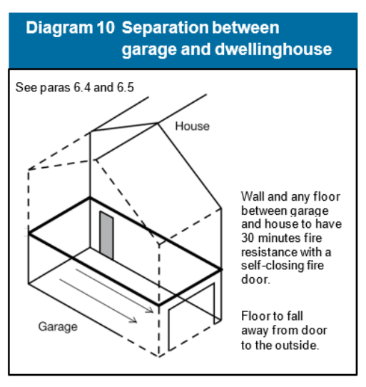
Note: Timber beams, joists, purlins and rafters may be built into or carried through a masonry or concrete compartment wall if the openings for them are kept as small as practicable and then fire-stopped. If trussed rafters bridge the wall, they should be designed so that failure of any part of the truss due to a fire in one compartment will not cause failure of any part of the truss in another compartment.
Compartment walls between buildings
6.7Compartment walls that are common to two or more buildings should run the full height of the building in a continuous vertical plane. Thus adjoining buildings should only be separated by walls, not floors.
6.8Compartment walls in a top storey beneath a roof should be continued through the roof space (see definition of compartment in Appendix E).
Junction of compartment wall or compartment floor with other walls
6.9Where a compartment wall or compartment floor meets another compartment wall, or an external wall, the junction should maintain the fire resistance of the compartmentation. Fire-stopping should meet the provisions of paragraphs 8.12 to 8.14.
6.10At the junction of a compartment floor with an external wall that has no fire resistance (such as a curtain wall) the external wall should be restrained at floor level to reduce the movement of the wall away from the floor when exposed to fire .
Junction of compartment wall with roof
6.11A compartment wall should be taken up to meet the underside of the roof covering or deck, with fire-stopping where necessary at the wall/ roof junction to maintain the continuity of fire resistance. The compartment wall should also be continued across any eaves.
Page 59
#Source page 59
Contents > Use of guidance > General introduction > Means of warning > Section 1 | 2 | 3 | 4 | 5 | 6 | 7 | 8 | 9 | 10 | 11 | 12 > Appendix A | B | C | D | E | F | G > Publications > Index
Section 6
6.12If a fire penetrates a roof near a compartment wall there is a risk that it will spread over the roof to the adjoining compartment. To reduce this risk either:
a.the wall should be extended up through the roof for a height of at least 375mm above the top surface of the adjoining roof covering (see Diagram 11a). Where there is a height difference of at least 375mm between two roofs or where the roof coverings on either side of the wall are AA, AB or AC this height may be reduced to 200mm; or
b.a zone of the roof 1500mm wide on either side of the wall should have a covering of designation AA, AB or AC. Any combustible boarding used as a substrate to the roof covering, wood wool slabs, or timber tiling battens that are carried over the compartment wall should be fully bedded in mortar or other suitable material over the width of the wall (see Diagram 11b).
Note: Double-skinned insulated roof sheeting with a thermoplastic core should incorporate a band of material of limited combustibility at least 300mm wide centered over the wall.
Openings in compartmentation
Openings in compartment walls separating buildings or occupancies
6.13Any openings in a compartment wall which is common to two or more buildings should be limited to those for:
a.a door which is needed to provide a means of escape in case of fire and which has the same fire resistance as that required for the wall (see Appendix B, Table B1) and is fitted in accordance with the provisions of Appendix B; and
b.the passage of a pipe which meets the provisions in Section 8.
Doors
6.14Information on fire doors may be found in Appendix B.
Page 60
#Source page 60
Contents > Use of guidance > General introduction > Means of warning > Section 1 | 2 | 3 | 4 | 5 | 6 | 7 | 8 | 9 | 10 | 11 | 12 > Appendix A | B | C | D | E | F | G > Publications > Index
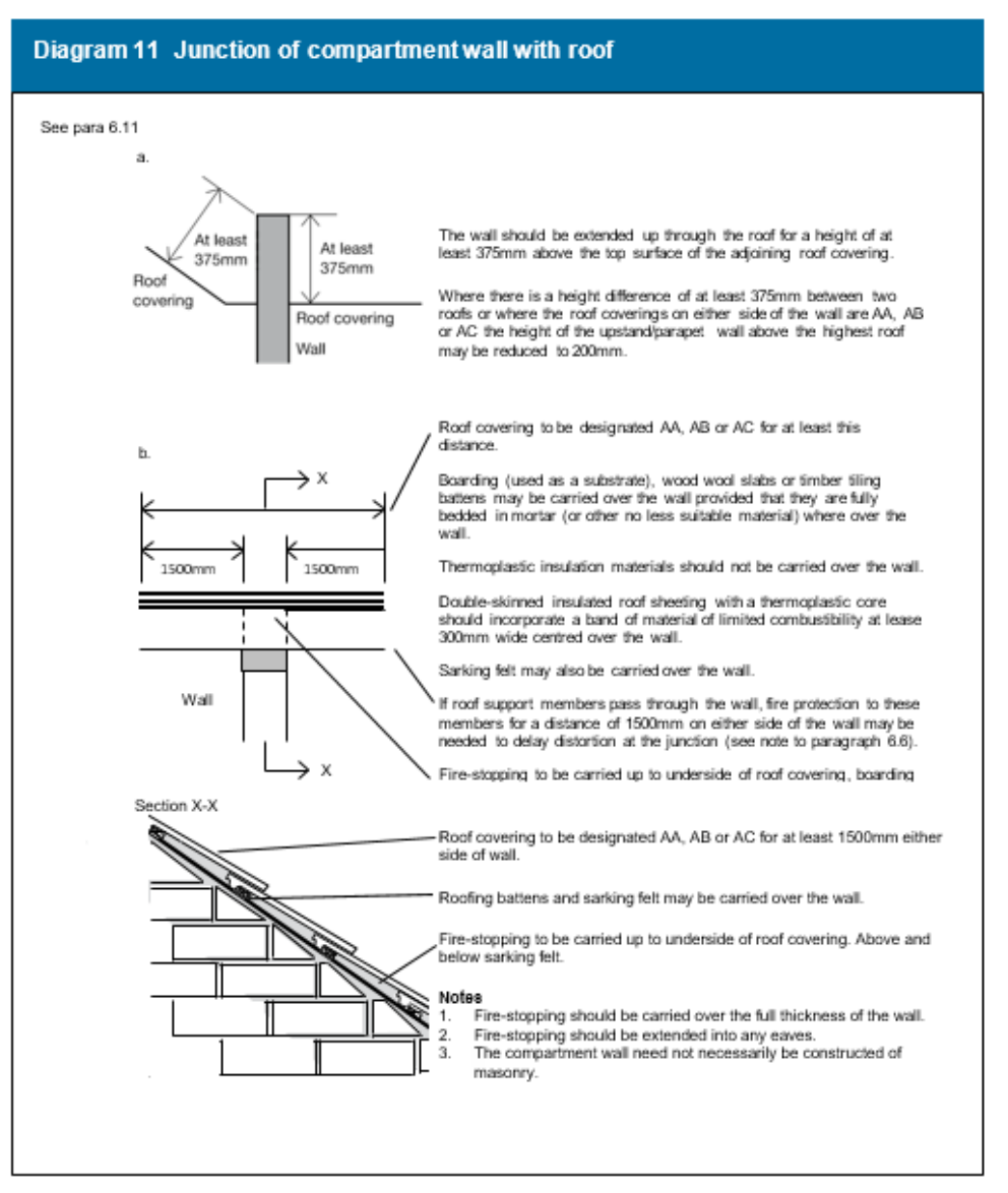
Section 7 B3
#Source page 61
Contents > Use of guidance > General introduction > Means of warning > Section 1 | 2 | 3 | 4 | 5 | 6 | 7 | 8 | 9 | 10 | 11 | 12 > Appendix A | B | C | D | E | F | G > Publications > Index
Section 7
Section 7 B3
Concealed spaces (cavities)
Introduction
7.1Concealed spaces or cavities in the construction of a building provide a ready route for smoke and flame spread e.g. in walls, floors, ceilings and roofs. As any spread is concealed, it presents a greater danger than would a more obvious weakness in the fabric of the building .
Provision of cavity barriers
7.2Provisions are given below for cavity barriers in specified locations. The provisions necessary to restrict the spread of smoke and flames through cavities are broadly for the purpose of sub-dividing cavities, which could otherwise form a pathway around a fire separating element, and closing the edges of cavities; therefore reducing the potential for unseen fire spread. See also paragraph 3.14.
Note: These should not be confused with fire stopping details, see Sections 6 and 8. Consideration should also be given to the construction and fixing of cavity barriers provided for these purposes and the extent to which openings in them should be protected. For guidance on these issues, see paragraphs 7.6 to 7.8 respectively.
7.3Cavity barriers should be provided at the edges of cavities, including around openings (such as window and door openings). Additionally, cavity barriers should be provided at the junction between an external cavity wall and a compartment wall that separates buildings, see Diagram 12; and at the top of such an external cavity wall, except where the cavity wall complies with Diagram 13.
It is important to continue any compartment wall up through a ceiling or roof cavity to maintain the standard of fire resistance – therefore compartment walls should be carried up to the roof, see paragraph 6.11. It is not appropriate to complete a line of compartment walls by fitting cavity barriers above them.
Page 62
#Source page 62
Contents > Use of guidance > General introduction > Means of warning > Section 1 | 2 | 3 | 4 | 5 | 6 | 7 | 8 | 9 | 10 | 11 | 12 > Appendix A | B | C | D | E | F | G > Publications > Index
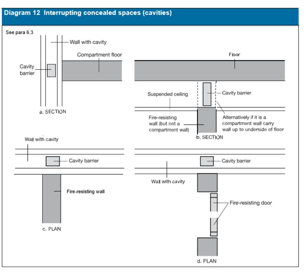
Double-skinned insulated roof sheeting
#Source page 63
Contents > Use of guidance > General introduction > Means of warning > Section 1 | 2 | 3 | 4 | 5 | 6 | 7 | 8 | 9 | 10 | 11 | 12 > Appendix A | B | C | D | E | F | G > Publications > Index
Section 7
Double-skinned insulated roof sheeting
7.4Cavity barriers need not be provided between double-skinned corrugated or profiled insulated roof sheeting, if the sheeting is a material of limited combustibility; and both surfaces of the insulating layer have a surface spread of flame of at least Class 0 or 1 (National class) or Class C-s3, d2 or better (European class) (see Appendix A); and make contact with the inner and outer skins of cladding.
Note: When a classification includes “s3, d2”, this means that there is no limit set for smoke production and/or flaming droplets/particles.
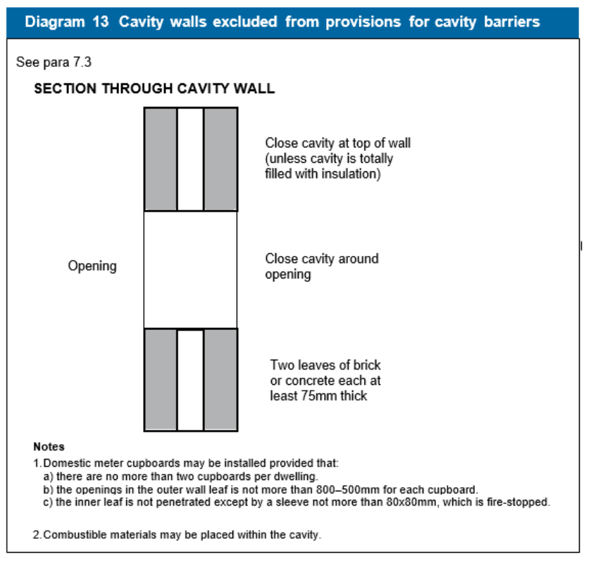
Construction and fixings for cavity barriers
7.5Every cavity barrier should be constructed to provide at least 30 minutes fire resistance and may be formed by any construction provided for another purpose if it meets the provisions for cavity barriers (see Appendix A, Table A1, item 10).
Page 64
#Source page 64
Contents > Use of guidance > General introduction > Means of warning > Section 1 | 2 | 3 | 4 | 5 | 6 | 7 | 8 | 9 | 10 | 11 | 12 > Appendix A | B | C | D | E | F | G > Publications > Index
Section 7
However, cavity barriers in a stud wall or partition, or provided around openings may be formed of:
a.steel at least 0.5mm thick; or
b.timber at least 38mm thick; or
c.polythene-sleeved mineral wool, or mineral wool slab, in either case under
compression when installed in the cavity; or d calcium silicate, cement-based or gypsum- based boards at least 12mm thick.
Note: Cavity barriers provided around openings may be formed by the window or door frame if the frame is constructed of steel or timber of the minimum thickness in (a) or (b) above as appropriate.
7.6A cavity barrier should, wherever possible, be tightly fitted to a rigid construction and mechanically fixed in position. Where this is not possible (for example, in the case of a junction with slates, tiles, corrugated sheeting or similar materials) the junction should be fire-stopped. Provisions for fire-stopping are set out in Section 8.
7.7Cavity barriers should also be fixed so that their performance is unlikely to be made ineffective by:
a.movement of the building due to subsidence, shrinkage or temperature change; and movement of the external envelope due to wind; and
b.collapse in a fire of any services penetrating them; and
c.failure in a fire of their fixings (but see note below); and
d.failure in a fire of any material or construction which they abut. (For example, if a suspended ceiling is continued over the top of a fire- resisting wall or partition, and direct connection is made between the ceiling and the cavity barrier above the line of the wall or partition, premature failure of the cavity barrier can occur when the ceiling collapses. However, this may not arise if the ceiling is designed to provide fire resistance of 30 minutes or more).
Note: Where cavity barriers are provided in roof spaces, the roof members to which they are fitted are not expected to have any fire resistance (for the purpose of supporting the cavity barrier(s)).
Openings in cavity barriers
7.8Any openings in a cavity barrier should be limited to those for:
a doors which have at least 30 minutes fire resistance (see Appendix B, Table B1, item 1(a)) and are fitted in accordance with the provisions of Appendix B;
b.the passage of pipes which meet the provisions in Section 8;
c.the passage of cables or conduits containing one or more cables;
d.openings fitted with a suitably mounted automatic fire damper; and
e.ducts which are fire-resisting or are fitted with a suitably mounted automatic fire damper where they pass through the cavity barrier.
Section 8 B3
#Source page 65
Contents > Use of guidance > General introduction > Means of warning > Section 1 | 2 | 3 | 4 | 5 | 6 | 7 | 8 | 9 | 10 | 11 | 12 > Appendix A | B | C | D | E | F | G > Publications > Index
Section 8
Section 8 B3
Protection of openings and fire stopping
Introduction
8.1Sections 8 and 9 make provisions for fire-separating elements and set out the circumstances in which there may be openings in them. This section deals with the protection of openings in such elements.
8.2If a fire-separating element is to be effective, then every joint, or imperfection of fit, or opening to allow services to pass through the element, should be adequately protected by sealing or fire-stopping so that the fire resistance of the element is not impaired.
8.3The measures in this section are intended to delay the passage of fire. They generally have the additional benefit of retarding smoke spread but the test specified in Appendix A for integrity does not directly stipulate criteria for the passage of smoke.
8.4Consideration should also be given to the effect of services that may be built into the construction that could adversely affect its fire resistance. For instance, where down-lighters, loudspeakers and other electrical accessories are installed, additional protection may be required to maintain the integrity of a wall or floor.
8.5Detailed guidance on door openings and fire doors is given in Appendix B.
Openings for pipes
8.6Pipes which pass through fire-separating elements (unless the pipe is in a protected shaft), should meet the appropriate provisions in alternatives A, B or C below.
Alternative A: Proprietary seals (any pipe diameter)
8.7Provide a proprietary sealing system which has been shown by test to maintain the fire resistance of the wall, floor or cavity barrier.
Alternative B: Pipes with a restricted diameter
8.8Where a proprietary sealing system is not used, fire-stopping may be used around the pipe, keeping the opening as small as possible. The nominal internal diameter of the pipe should not be more than the relevant dimension given in Table 3.
Section 8
#Source page 66
9| 10 | 11 | 12 > Appendix A | B | C | D | E | F | G > Publications > Index
Section 8
| Situation | Pipe material and maximum nominal internal diameter (mm) | ||
|---|---|---|---|
| (a) (b) (c) Lead, aluminium, Any other material Non-combustible (1) aluminium alloy, material uPVC (2) | |||
| 1 Wall separating dwellinghouses | 160 | 160 (stack pipe) (3) 110 (branch pipe) (3) | 40 |
| 2 Wall or floor separating a dwellinghouse from an attached garage | 160 | 110 | 40 |
| 3. Any other situation | 160 | 40 | 40 |
Note:
1.Any non-combustible material (such as cast iron, copper or steel) which, if exposed to a temperature of 800ºC, will not soften or fracture to the extent that flame or hot gas will pass through the wall of the pipe.
2.uPVC pipes complying with BS 4514 and uPVC pipes complying with BS 5255.
3.These diameters are only in relation to pipes forming part of an above-ground drainage system and enclosed as shown in Diagram 15. In other cases the maximum diameters against situation 3 apply.
Alternative C: sleeving
#Source page 67
Contents > Use of guidance > General introduction > Means of warning > Section 1 | 2 | 3 | 4 | 5 | 6 | 7 | 8 | 9 | 10 | 11 | 12 > Appendix A | B | C | D | E | F | G > Publications > Index
Section 8
Alternative C: sleeving
8.9A pipe of lead, aluminium, aluminium alloy, fibre-cement or uPVC, with a maximum nominal internal diameter of 160mm, may be used with a sleeving of non- combustible pipe as shown in Diagram 14. The specification for non-combustible and uPVC pipes is given in the notes to Table 3.
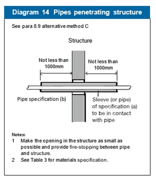
Page 68
#Source page 68
Contents > Use of guidance > General introduction > Means of warning > Section 1 | 2 | 3 | 4 | 5 | 6 | 7 | 8 | 9 | 10 | 11 | 12 > Appendix A | B | C | D | E | F | G > Publications > Index
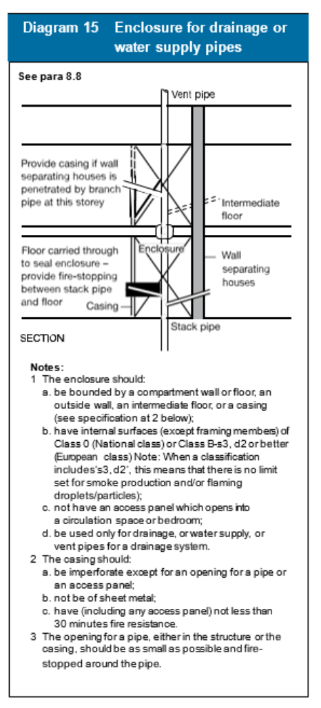
Ventilation ducts, flues etc.
#Source page 69
Contents > Use of guidance > General introduction > Means of warning > Section 1 | 2 | 3 | 4 | 5 | 6 | 7 | 8 | 9 | 10 | 11 | 12 > Appendix A | B | C | D | E | F | G > Publications > Index
Section 8
Ventilation ducts, flues etc.
8.10Air circulation systems which circulate air within an individual dwellinghouse with a floor more than 4.5m above ground level should meet the guidance given in paragraph 3.16. Where ventilation ducts pass through compartment walls into another building then the guidance given in Approved Document B Volume 2 should be followed.
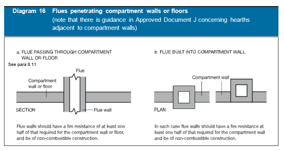
8.11If a flue or duct containing flues or appliance ventilation duct(s), passes through a compartment wall or compartment floor, or is built into a compartment wall, each wall of the flue or duct should have a fire resistance of at least half that of the wall or floor in order to prevent the by-passing of the compartmentation (see Diagram 16).
Fire-stopping
8.12In addition to any other provisions in this document for fire-stopping:
a.joints between fire-separating elements should be fire-stopped; and
b.all openings for pipes, ducts, conduits or cables to pass through any part of a fire-separating element should be:
i. kept as few in number as possible; and ii. kept as small as practicable; and iii. fire-stopped (which in the case of a pipe or duct should allow thermal movement).
Page 70
#Source page 70
Contents > Use of guidance > General introduction > Means of warning > Section 1 | 2 | 3 | 4 | 5 | 6 | 7 | 8 | 9 | 10 | 11 | 12 > Appendix A | B | C | D | E | F | G > Publications > Index
Section 8
8.13To prevent displacement, materials used for fire-stopping should be reinforced with (or supported by) materials of limited combustibility in the following circumstances:
a.in all cases where the unsupported span is greater than 100mm; and
b.in any other case where non-rigid materials are used (unless they have been shown to be satisfactory by test).
8.14Proprietary fire-stopping and sealing systems, (including those designed for service penetrations) which have been shown by test to maintain the fire resistance of the wall or other element, are available and may be used.
Other fire-stopping materials include:
•cement mortar;
•gypsum-based plaster;
•cement-based or gypsum-based vermiculite/perlite mixes;
•glass fibre, crushed rock, blast furnace slag or ceramic-based products (with or without resin binders); and
•intumescent mastics.
These may be used in situations appropriate to the particular material. Not all of them will be suitable in every situation.
Guidance on the process of design, installation and maintenance of passive fire protection is available in Ensuring Best Practice for Passive Fire Protection in Buildings (ISBN: 1 87040 919 1) produced by the Association for Specialist Fire Protection (ASFP).
Further information on the generic types of systems available, information about their suitability for different applications and guidance on test methods is given in the ASFP Red Book: Fire Stopping and Penetration Seals for the Construction Industry – the ‘Red Book’ published by the Association for Specialist Fire Protection and freely available from the ASFP website at www.asfp.org.uk.
External Fire Spread B4 The Requirement
#Source page 71
Contents > Use of guidance > General introduction > Means of warning > Section 1 | 2 | 3 | 4 | 5 | 6 | 7 | 8 | 9 | 10 | 11 | 12 > Appendix A | B | C | D | E | F | G > Publications > Index
Section 8
External Fire Spread B4 The Requirement
This Approved Document deals with the following Requirement from Part B of Schedule 1 to the Building Regulations 2010.
Requirement Limits on application
| External fire spread B4. (1) The external walls of the building shall adequately resist the spread of fire over the walls and from one building to another, having regard to the height, use and position of the building. (2) The roof of the building shall adequately resist the spread of fire over the roof and from one building to another, having regard to the use and position of the building. |
Guidance B4
#Source page 72
Contents > Use of guidance > General introduction > Means of warning > Section 1 | 2 | 3 | 4 | 5 | 6 | 7 | 8 | 9 | 10 | 11 | 12 > Appendix A | B | C | D | E | F | G > Publications > Index
Section 8
Guidance B4
Performance
In the Welsh Ministers’ view the Requirements of B4 will be met:
a.if the external walls are constructed so that the risk of ignition from an external source, and the spread of fire over their surfaces, is restricted by making provision for them to have low rates of heat release;
b.if the amount of unprotected area in the side of the building is restricted so as to limit the amount of thermal radiation that can pass through the wall, taking the distance between the wall and the boundary into account; and
c.if the roof is constructed so that the risk of spread of flame and/or fire penetration from an external fire source is restricted.
In each case so as to limit the risk of a fire spreading from the building to a building beyond the boundary, or vice versa.
The extent to which this is necessary is dependent on the use of the building, its distance from the boundary and, in some cases, its height.
Introduction
External walls
B4.i The construction of external walls and the separation between buildings to prevent external fire spread are closely related.
The chances of fire spreading across an open space between buildings, and the consequences if it does, depend on:
a.the size and intensity of the fire in the building concerned;
b.the distance between the buildings;
c.the fire protection given by their facing sides; and
d.the risk presented to people in the other building(s).
B4.ii Provisions are made in Section 9 for the fire resistance of external walls and to limit the susceptibility of the external surface of walls to ignition and to fire spread.
B4.iii Provisions are made in Section 10 to limit the extent of openings and other unprotected areas in external walls in order to reduce the risk of fire spread by radiation.
Roofs
B4.iv Provisions are made in Section 11 for reducing the risk of fire spread between roofs and over the surfaces of roofs.
Section 9 B4
#Source page 73
Contents > Use of guidance > General introduction > Means of warning > Section 1 | 2 | 3 | 4 | 5 | 6 | 7 | 8 | 9 | 10 | 11 | 12 > Appendix A | B | C | D | E | F | G > Publications > Index
Section 9
Section 9 B4
Construction of external walls
Introduction
9.1Provisions are made in this section for the external walls of the building to have sufficient fire resistance to prevent fire spread across the relevant boundary. The provisions are closely linked with those for space separation in Section 10 which sets out limits on the amount of unprotected area of wall. As the limits depend on the distance of the wall from the relevant boundary, it is possible for some or all of the walls to have no fire resistance, except for any parts which are loadbearing (see paragraph B3.iii).
External walls are elements of structure and the relevant period of fire resistance (specified in Appendix A) depends on the use, height and size of the building concerned. If the wall is 1000mm or more from the relevant boundary, a reduced standard of fire resistance is accepted in most cases and the wall only needs fire resistance from the inside.
9.2Provisions are also made to restrict the combustibility of external walls of buildings that are less than 1000mm from the relevant boundary. This is in order to reduce the surface’s susceptibility to ignition from an external source. In the guidance to Requirement B3, provisions are made in Section 5 for internal and external loadbearing walls to maintain their loadbearing function in the event of fire.
Fire resistance standard
9.3The external walls of the building should have the appropriate fire resistance given in Appendix A, Table A1, unless they form an unprotected area under the provisions of Section 10.
External surfaces
9.4The external surfaces of walls within 1000mm of the relevant boundary should meet Class 0 (National Class) or Class B-s3,d2 or better (European class). The total amount of combustible material on walls more than 1000mm from the relevant boundary may be limited in practice by the provisions for space separation in Section 10 (see paragraphs 10.7 to 10.17).
Section 10 B4
#Source page 74
Contents > Use of guidance > General introduction > Means of warning > Section 1 | 2 | 3 | 4 | 5 | 6 | 7 | 8 | 9 | 10 | 11 | 12 > Appendix A | B | C | D | E | F | G > Publications > Index
Section 10
Section 10 B4
Space separation
Introduction
10.1The provisions in this Section are based on a number of assumptions and, whilst some of these may differ from the circumstances of a particular case, together they enable a reasonable standard of space separation to be specified. The provisions limit the extent of unprotected areas in the sides of a building (such as openings and areas with a combustible surface) which will not give adequate protection against the external spread of fire from one building to another.
A roof is not subject to the provisions in this Section unless it is pitched at an angle greater than 70º to the horizontal (see definition for ‘external wall’ in Appendix E). Similarly, vertical parts of a pitched roof such as dormer windows (which taken in isolation might be regarded as a wall), would not need to meet the following provisions unless the slope of the roof exceeds 70º. It is a matter of judgement whether a continuous run of dormer windows occupying most of a steeply pitched roof should be treated as a wall rather than a roof.
10.2The assumptions are:
a.that the size of a fire will depend on the compartmentation of the building, so that a fire may involve a complete compartment, but will not spread to other compartments;
b.that the intensity of the fire is related to the use of the building (i.e. purpose group), but that it can be moderated by an automatic fire suppression system;
c.that Residential (1 and 2) and Assembly and Recreation (5) Purpose Groups represent a greater life risk than other uses;
d.that there is a building on the far side of the boundary that has a similar elevation to the one in question and that it is at the same distance from the common boundary; and
e.that the amount of radiation that passes through any part of the external wall that has fire resistance may be discounted.
10.3Where a reduced separation distance is desired (or an increased amount of unprotected area) it may be advantageous to introduce additional compartment walls and/or floors.
Boundaries
10.4The use of the distance to a boundary, rather than to another building, in measuring the separation distance, makes it possible to calculate the allowable proportion of unprotected areas, regardless of whether there is a building on an adjoining site and regardless of the site of that building and the extent of any unprotected areas that it might have.
Relevant boundaries
#Source page 75
Contents > Use of guidance > General introduction > Means of warning > Section 1 | 2 | 3 | 4 | 5 | 6 | 7 | 8 | 9 | 10 | 11 | 12 > Appendix A | B | C | D | E | F | G > Publications > Index
Section 10
A wall is treated as facing a boundary if it makes an angle with it of 80º or less (see Diagram 17).
Usually only the distance to the actual boundary of the site needs to be considered. But, in some circumstances, when the site boundary adjoins a space where further development is unlikely, such as a road, then part of the adjoining space may be included as falling within the relevant boundary for the purposes of this section. The meaning of the term boundary is explained in Diagram 17.
Relevant boundaries
10.5The boundary which a wall faces, whether it is the actual boundary of the site or a notional boundary, is called the relevant boundary (see Diagrams 17 and 18).
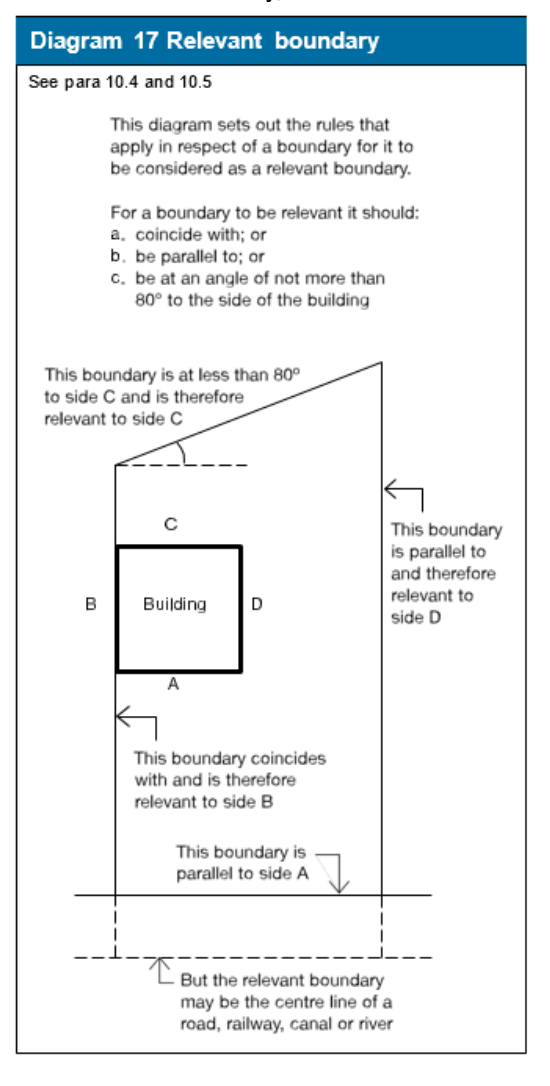
Notional boundaries
#Source page 76
Contents > Use of guidance > General introduction > Means of warning > Section 1 | 2 | 3 | 4 | 5 | 6 | 7 | 8 | 9 | 10 | 11 | 12 > Appendix A | B | C | D | E | F | G > Publications > Index
Section 10
Notional boundaries
10.6The distances to other buildings on the same site also need to be considered. This is done by assuming that there is a boundary between those buildings. This assumed boundary is called a notional boundary. The appropriate rules are given in Diagram 18.
Unprotected areas
Unprotected areas and fire resistance
10.7Any part of an external wall which has less fire resistance than the appropriate amount given in Appendix A, Table A2, is considered to be an unprotected area.
Status of combustible surface materials as unprotected area
10.8If an external wall has the appropriate fire resistance, but has combustible material more than 1mm thick as its external surface, then that wall is counted as an unprotected area amounting to half the actual area of the combustible material, see Diagram 19. (For the purposes of this provision, a material with a Class 0 rating (National class) or Class B-s3,d2 rating (European class) (see Appendix A, paragraphs 10 and 16) need not be counted as unprotected area).
Note: When a classification includes ‘s3, d2’, this means that there is no limit set for smoke production and/or flaming droplets/particles.
Page 77
#Source page 77
Contents > Use of guidance > General introduction > Means of warning > Section 1 | 2 | 3 | 4 | 5 | 6 | 7 | 8 | 9 | 10 | 11 | 12 > Appendix A | B | C | D | E | F | G > Publications > Index
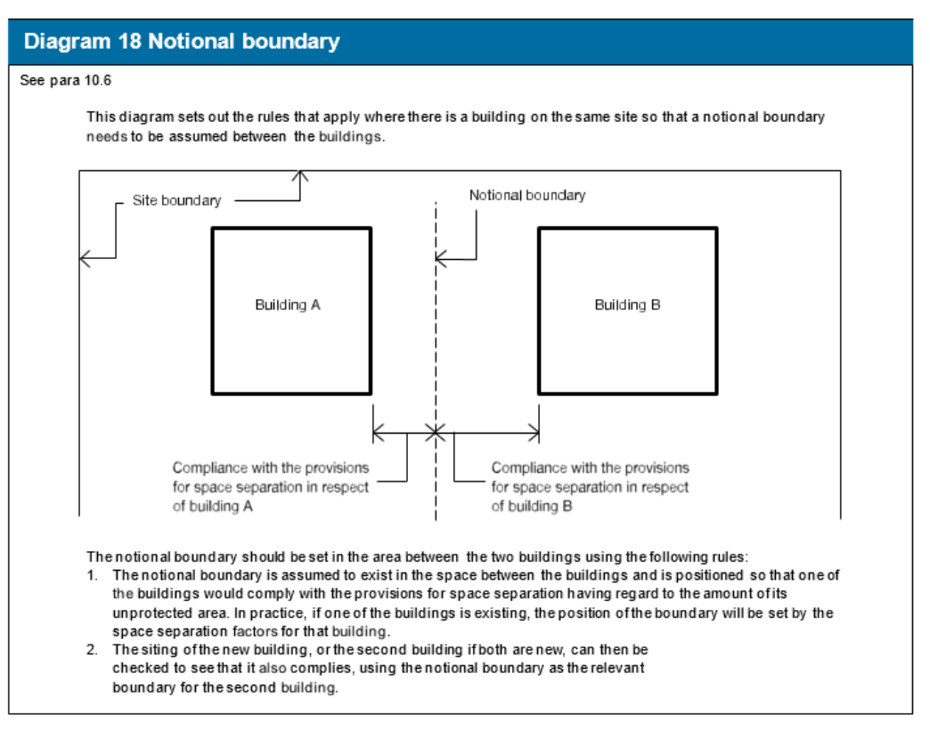
Small unprotected areas
#Source page 78
Contents > Use of guidance > General introduction > Means of warning > Section 1 | 2 | 3 | 4 | 5 | 6 | 7 | 8 | 9 | 10 | 11 | 12 > Appendix A | B | C | D | E | F | G > Publications > Index
Section 10
Small unprotected areas
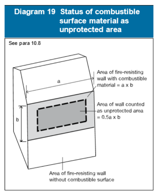
10.9Small unprotected areas in an otherwise protected area of wall are considered to pose a negligible risk of fire spread and may be disregarded. Diagram 20 shows the constraints that apply to the placing of such areas in relation to each other and to lines of compartmentation inside the building. These constraints vary according to the size of each unprotected area.
Canopies
10.10Some canopy structures would be exempt from the application of the Building Regulations by falling within Class 6 or Class 7 of Schedule 2 to the Regulations (Exempt Buildings and Work).Many others may not meet the exemption criteria and, in such cases, the provisions in this section about limits of unprotected areas could be onerous.
In the case of a canopy attached to the side of a building, provided that the edges of the canopy are at least 2m from the relevant boundary, separation distance may be determined from the wall rather than the edge of the canopy (see Diagram 21).
External walls within 1000mm of the relevant boundary
10.11A wall situated within 1000mm from any point on the relevant boundary, including a wall coincident with the boundary, will meet the provisions for space separation if:
a.the only unprotected areas are those shown in Diagram 20; and
b.the rest of the wall is fire-resisting from both sides.
Page 79
#Source page 79
Contents > Use of guidance > General introduction > Means of warning > Section 1 | 2 | 3 | 4 | 5 | 6 | 7 | 8 | 9 | 10 | 11 | 12 > Appendix A | B | C | D | E | F | G > Publications > Index
Section 10
External walls 1000mm or more from the relevant boundary
10.12A wall situated at least 1000mm from any point on the relevant boundary will meet the provisions for space separation if:
a.the extent of unprotected area does not exceed that given by one of the methods referred to in paragraph 10.13; and
b.the rest of the wall (if any) is fire-resisting.
Methods for calculating acceptable unprotected area
10.13Two simple methods are given in this Approved Document for calculating the acceptable amount of unprotected area in an external wall that is at least 1000mm from any point on the relevant boundary. (For walls within 1000mm of the boundary see paragraph 10.11 above).
Method 1 may be used for small residential buildings and is set out in paragraph 10.16.
Method 2 may be used for most buildings or compartments for which Method 1 is not appropriate, and is set out in paragraph 10.17.
There are other more precise methods, described in a BRE report External fire spread: Building separation and boundary distances (BR 187, BRE 1991), which may be used instead of Methods 1 and 2. The ‘Enclosing Rectangle’ and ‘Aggregate Notional Area’ methods are included in the BRE report.
Basis for calculating acceptable unprotected area
10.14The basis of Methods 1 and 2 was originally set out in Fire Research Technical Paper No 5,1963. This has been reprinted as part of the BRE report referred to in paragraph 10.13. The aim is to ensure that the building is separated from the boundary by at least half the distance at which the total thermal radiation intensity received from all unprotected areas in the wall would be 12.6 kw/m2 (in still air), assuming the radiation intensity at each unprotected area is 84 kw/m2.
Page 80
#Source page 80
Contents > Use of guidance > General introduction > Means of warning > Section 1 | 2 | 3 | 4 | 5 | 6 | 7 | 8 | 9 | 10 | 11 | 12 > Appendix A | B | C | D | E | F | G > Publications > Index
Section 10
Automatic fire suppression systems
10.15If a building is fitted throughout with an automatic fire suppression system, it is reasonable to assume that the intensity and extent of a fire will be reduced. The automatic fire suppression system should meet the relevant recommendations of a suitable, fully implemented, technical standard such as BS 9251: Fire Sprinkler systems for domestic and residential occupancies. Code of practice or equivalent technical standard. In these circumstances the boundary distance may be half that for an otherwise similar, but unsuppressed, building, subject to there being a minimum distance of 1000mm. Alternatively, the amount of unprotected area may be doubled if the boundary distance is maintained.
Note: The presence of an automatic fire suppression system may be taken into account in a similar way when using the BRE report referred to in paragraph 10.14.
Method 1
10.16This method applies only to a building, which is 1000mm or more from any point on the relevant boundary and meets the following rules for determining the maximum unprotected area, which should be read with Diagram 22:
a.The building should not exceed 3 storeys in height (basements are not counted) or be more than 24m in length; and
b.Each side of the building will meet the provisions for space separation if:
i. the distance of the side of the building from the relevant boundary; and ii the extent of the unprotected area, are within the limits given in Diagram 22; and
Note: In calculating the maximum unprotected area, any areas falling within the limits shown in Diagram 20, and referred to in paragraph 10.9, can be disregarded.
c. Any parts of the side of the building in excess of the maximum unprotected area should be fire-resisting.
Page 81
#Source page 81
Contents > Use of guidance > General introduction > Means of warning > Section 1 | 2 | 3 | 4 | 5 | 6 | 7 | 8 | 9 | 10 | 11 | 12 > Appendix A | B | C | D | E | F | G > Publications > Index
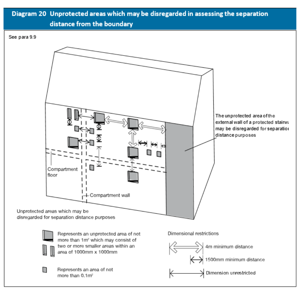
Page 82
#Source page 82
Contents > Use of guidance > General introduction > Means of warning > Section 1 | 2 | 3 | 4 | 5 | 6 | 7 | 8 | 9 | 10 | 11 | 12 > Appendix A | B | C | D | E | F | G > Publications > Index
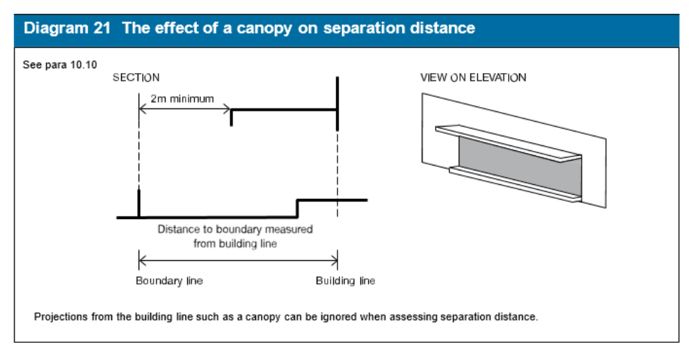
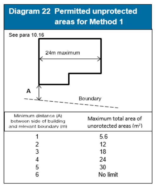
Page 83
#Source page 83
Contents > Use of guidance > General introduction > Means of warning > Section 1 | 2 | 3 | 4 | 5 | 6 | 7 | 8 | 9 | 10 | 11 | 12 > Appendix A | B | C | D | E | F | G > Publications > Index
Section 10
Method 2
10.17This method applies to a dwellinghouse which is more than 1000mm from any point on the relevant boundary. The following rules for determining the maximum unprotected area should be read with Table 4.
a. The building or compartment should not exceed 10m in height.
Note: For any building or compartment more than 10m in height, the methods set out in the BRE report External fire spread: Building separation and boundary distances can be applied.
b. Each side of the building will meet the provisions for space separation if either:
i. the distance of the side of the building from the relevant boundary; or ii. the extent of unprotected area, are within the appropriate limits given in Table 4.
Note: In calculating the maximum unprotected area, any areas shown in Diagram 20, and referred to in paragraph 10.9, can be disregarded.
c. Any parts of the side of the building in excess of the maximum unprotected area should be fire-resisting.
Notes:
a Intermediate values may be obtained by interpolation.
b.For buildings which are fitted throughout with an automatic sprinkler system, see para 10.15.
c.The total percentage of unprotected area is found by dividing the total unprotected area by the area of rectangle that encloses all the unprotected areas and multiplying the result by 100.
Section 11 B4
#Source page 84
Contents > Use of guidance > General introduction > Means of warning > Section 1 | 2 | 3 | 4 | 5 | 6 | 7 | 8 | 9 | 10 | 11 | 12 > Appendix A | B | C | D | E | F | G > Publications > Index
Section 11
Section 11 B4
Roof coverings
Introduction
11.1The provisions in this section limit the use, near a boundary, of roof coverings which will not give adequate protection against the spread of fire over them. The term roof covering is used to describe constructions which may consist of one or more layers of material, but does not refer to the roof structure as a whole. The provisions in this Section are principally concerned with the performance of roofs when exposed to fire from the outside.
11.2The circumstances when a roof is subject to the provisions in Section 10 for space separation are explained in paragraph 10.1.
Other controls on roofs
11.3There are provisions concerning the fire properties of roofs in other Sections of this document. In the guidance to B1 (paragraph 3.10) there are provisions for roofs that are part of a means of escape. In the guidance to B2 there are provisions for the internal surfaces of rooflights as part of the internal lining of a room or circulation space. In the guidance to B3 there are provisions in Section 5 for roofs which are used as a floor and in Section 7 for roofs that pass over the top of a compartment wall.
Classification of performance
11.4The performance of roof coverings is designated by reference to the test methods specified in BS 476-3:2004 Fire tests on building materials and structures. Classification and method of test for external fire exposure to roofs or determined in accordance with BS EN 13501-5:2005 Fire classification of construction products and building elements. Classification using data from external fire exposure to roof tests, as described in Appendix A. The notional performance of some common roof coverings is given in Table A5 of Appendix A.
Rooflights are controlled on a similar basis, and plastic rooflights described in paragraphs 11.6 and 11.7 may also be used.
Separation distances
11.5The separation distance is the minimum distance from the roof (or part of the roof) to the relevant boundary, which may be a notional boundary.
Table 5 sets out separation distances according to the type of roof covering and the size and use of the building. There are no restrictions on the use of roof coverings designated AA, AB or AC (National class) or BROOF(t4) (European class) classification. In addition, roof covering products (and/or materials) as defined in Commission Decision 2000/553/EC of 6 September 2000 implementing
Plastic rooflights
#Source page 85
Contents > Use of guidance > General introduction > Means of warning > Section 1 | 2 | 3 | 4 | 5 | 6 | 7 | 8 | 9 | 10 | 11 | 12 > Appendix A | B | C | D | E | F | G > Publications > Index
Section 11
Council Directive 89/106/EEC as regards the external fire performance of roof coverings can be considered to fulfil all of the requirements for performance characteristic ‘external fire performance’ without the need for testing provided that any national provisions on the design and execution of works are fulfilled.
Note: The boundary formed by the wall separating a pair of semi-detached houses may be disregarded for the purposes of this Section (but see Section 6, Diagram 11(b), which deals with roofs passing over the top of a compartment wall).
Plastic rooflights
11.6Table 6 sets out the limitations on the use of plastic rooflights which have at least a Class 3 (National class) or Class D-s3, d2 (European class) lower surface, and Table 7 sets out the limitations on the use of thermoplastic materials with a TP(a) rigid or TP(b) classification (see also Diagram 23). The method of classifying thermoplastic materials is given in Appendix A.
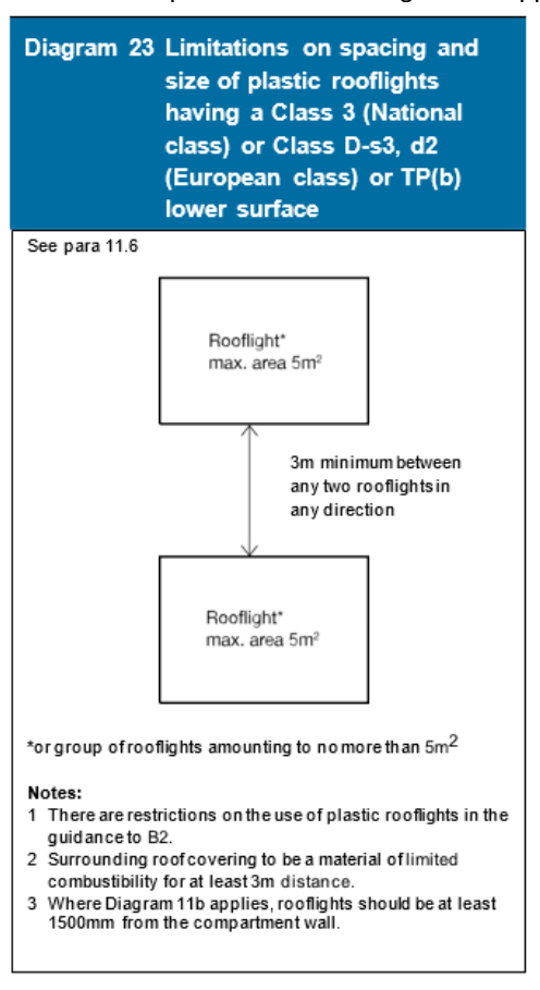
Page 86
#Source page 86
Contents > Use of guidance > General introduction > Means of warning > Section 1 | 2 | 3 | 4 | 5 | 6 | 7 | 8 | 9 | 10 | 11 | 12 > Appendix A | B | C | D | E | F | G > Publications > Index
Section 11
11.7When used in rooflights, a rigid thermoplastic sheet product made from polycarbonate or from unplasticised PVC, which achieves a Class 1 (National class) rating for surface spread of flame when tested to BS 476-7:1997 (or 1987 or 1971), or Class C-s3,d2 (European class) can be regarded as having an AA (National class) designation or BROOF(t4) (European class) classification, other than for the purposes of Diagram 11.
Unwired glass in rooflights
11.8When used in rooflights, unwired glass at least 4mm thick can be regarded as having an AA designation (National class) or BROOF (t4) (European class) classification.
Thatch and wood shingles
11.9Thatch and wood shingles should be regarded as having an AD/BD/CD designation or EROOF(t4) (European class) classification in Table 5 if performance under BS 476-3:2004 (or 1958) or BS EN 13501-5 cannot be established.
Note: Consideration can be given to thatched roofs being closer to the boundary than shown in Table 5 if, for example, the following precautions (based on Thatched buildings. New properties and extensions [the ‘Dorset Model’]) are incorporated in the design:
a.the rafters are overdrawn with construction having not less than 30 minutes fire resistance;
b.the guidance given in Approved Document J Combustion appliances and fuel storage is followed; and
c.the smoke alarm installation (see Section 1) extends to the roof space.
Page 87
#Source page 87
Section 11
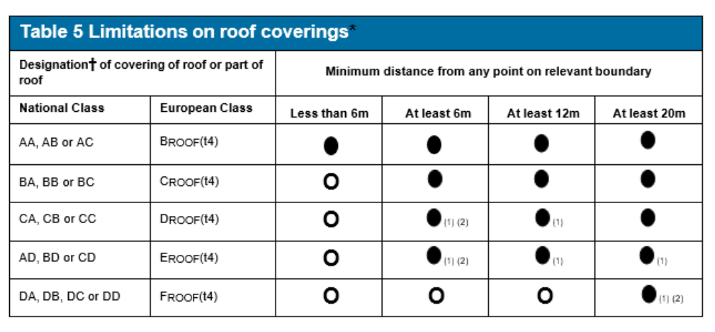
● Acceptable. O Not acceptable.
1. Not acceptable on any of the following buildings:
a.Houses in terraces of three or more houses.
b.Any other buildings with a cubic capacity of more than 1500m³.
2.Acceptable on buildings not listed in Note 1, provided that part of the roof is no more than 3m² in area and is at least 1500mm from any similar part, with the roof between the parts covered with a material of limited combustibility.
Notes:
* See paragraph 11.8 for limitations on glass; paragraph 11.9 for limitations on thatch and wood shingles; and paragraphs 11.6 and 11.7 and Tables 6 and 7 for limitations on plastic rooflights.
† The designation of external roof surfaces is explained in Appendix A. (See Table A5 for notional designations of roof coverings.) Separation distances do not apply to the boundary between roofs of a pair of semi- detached houses (see para 11.5) and to enclosed/ covered walkways. However, see Diagram 11 if the roof passes over the top of a compartment wall.
Openable polycarbonate and PVC rooflights which achieve a Class 1 (National class) or Class C-s3, d2 (European class) rating by test, see paragraph 11.7, may be regarded as having an AA (National class) designation or BROOF(t4) (European class) classification.
The National classifications do not automatically equate with the equivalent classifications in the European column, therefore products cannot typically assume a European class unless they have been tested accordingly.
Section 11
#Source page 88
| Minimum classification on lower surface (1) | Space which rooflight can serve | Minimum distance from any point on relevant boundary to rooflight with an external designation† of: | |
|---|---|---|---|
| AD BD CD (National class) EROOF(t4) (European class) CA CB CC or DROOF(t4) (European class) | DA DB DC DD or (National class) or FROOF(t4) (European class) | ||
| Class 3 (National class) or a. Balcony, verandah, Class D-s3, d2 (European class) carport or covered way, which has at least one longer side wholly or permanently open b. Detached swimming pool c. Conservatory, garage or outbuilding, with a maximum floor area 2 of 40m | 6m | 20m | |
| (2) d. Circulation space (except a protected stairway) (2) e. Room | (3) 6m | (3) 20m |
Notes: † The designation of external roof surfaces is explained in Appendix A. None of the above designations are suitable for protected stairways. Polycarbonate and PVC rooflights which achieve a Class 1 (National class) or Class C-s3, d2 (European class) rating by test, see paragraph 11.7, may be regarded as having an AA designation (National class) or BROOF(t4) (European class) classification. The National classifications do not automatically equate with the equivalent classifications in the European column, therefore products cannot typically assume a European class unless they have been tested accordingly. Where Diagram 11b applies, rooflights should be at least 1.5m from the compartment wall. Products may have upper and lower surfaces with different properties if they have double skins or are laminates of different materials; in which case the more onerous distance (from Tables 6 and 7) applies.
1.See also the guidance to B2.
2.Single skin rooflight only, in the case of non-thermoplastic material.
3.The rooflight should also meet the provisions of Diagram 23.
Section 11
#Source page 89
| Minimum classification on lower surface (1) | Space which rooflight can serve | Minimum distance from any point on relevant boundary to rooflight with an external surface classification (1) of: | |
|---|---|---|---|
| TP(a) | TP(b) | ||
| 1. TP(a) rigid | Any space except a protected stairway | 6m (2) | Not applicable |
| 2. TP(b) | a. Balcony, verandah, carport or covered way, which has at least one longer side wholly or permanently open b. Detached swimming pool c. Conservatory, garage or outbuilding, with a maximum floor 2 area of 40m | Not applicable | 6m |
| d. Circulation space (3) (except a protected stairway) e. Room (3) | Not applicable | 6m (4) |
Notes:
None of the above designations are suitable for protected stairways.. Polycarbonate and PVC rooflights which achieve a Class 1 (National class) or Class C-s3, d2 (European class) rating by test, see paragraph 11.7, may be regarded as having an AA designation (National class) or BROOF(t4) (European class) classification. Where Diagram 11b applies, rooflights should be at least 1.5m from the compartment wall. Products may have upper and lower surfaces with different properties if they have double skins or are laminates of different materials; in which case the more onerous distance (from Tables 6 and 7) applies. The National classifications do not automatically equate with the equivalent classifications in the European column, therefore products cannot typically assume a European class unless they have been tested accordingly.
1.See also the guidance to B2.
2.No limit in the case of any space described in 2a, b &c.
3.Single skin rooflight only, in the case of non-thermoplastic material.
4.The rooflight should also meet the provisions of Diagram 23.
Access and facilities for the B5 Fire and Rescue Service The Requirement
#Source page 90
Section 11
Access and facilities for the B5 Fire and Rescue Service The Requirement
This Approved Document deals with the following Requirement from Part B of Schedule 1 to the Building Regulations 2010 (as amended).
Requirement
Access and facilities for the fire service building.
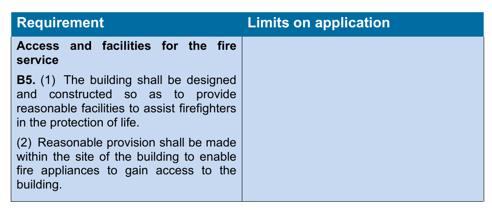
Guidance
#Source page 91
Section 11
Guidance
Performance
In the Welsh Ministers’ view the Requirements of B5 will be met:
a.if there is sufficient means of external access to enable fire appliances to be brought near to the building for effective use;
b.if there is sufficient means of access into, and within, the building for firefighting personnel to effect search and rescue and fight fire;
c.if the building is provided with sufficient internal fire mains and other facilities to assist firefighters in their tasks; and
d.if the building is provided with adequate means for venting heat and smoke from a fire in a basement.
These access arrangements and facilities are only required in the interests of the health and safety of people in and around the building. The extent to which they are required will depend on the use and size of the building in so far as it affects the health and safety of those people.
Introduction
B5.i The main factor determining the facilities needed to assist the fire and rescue service is the size of the building. Generally speaking firefighting is carried out within the building.
For dwellinghouses, it is usually only necessary to ensure that the building is sufficiently close to a point accessible to fire and rescue service vehicles (see paragraph 12.2). For very large houses additional measures may be necessary. The guidance given in Approved Document B Volume 2 (Buildings other than dwellinghouses) may be applicable.
If it is proposed to deviate from the general guidance in Section 12 then it would be advisable to seek advice from the Fire and Rescue Service at the earliest opportunity.
Section 12 B5
#Source page 92
Section 12
Section 12 B5
Vehicle access
Introduction
12.1For the purposes of this Approved Document, vehicle access to the exterior of a building is needed to enable high reach appliances, such as turntable ladders and hydraulic platforms, to be used and to enable pumping appliances to supply water and equipment for firefighting, search and rescue activities.
Vehicle access routes and hard-standings should meet the criteria described in paragraph 12.4 where they are to be used by fire and rescue service vehicles.
Note: Requirements cannot be made under the Building Regulations for work to be done outside the site of the works shown on the deposited plans, building notice or initial notice. In this connection it may not always be reasonable to upgrade an existing route across a site to a small building such as a single dwellinghouse. The options in such a case, from doing no work to upgrading certain features of the route, e.g. a sharp bend, should be considered by the Building Control Body in consultation with the fire and rescue service.
12.2There should be vehicle access for a pump appliance to within 60m of all points within the dwellinghouse (45m if not provided with an automatic fire suppression system).
12.3Every elevation to which vehicle access is provided in accordance with paragraph
12.2should have a suitable door(s), not less than 750mm wide, giving access to the interior of the building.
Design of access routes and hard-standings
12.4A vehicle access route may be a road or other route which, including any inspection covers and the like, meets the standards in Table 8 and paragraph 12.5.
12.5Turning facilities should be provided in any dead end access route that is more than 20m long (see Diagram 24). This can be by a hammerhead or turning circle, designed on the basis of Table 8.
Section 12
#Source page 93
| Appliance type | Minimum width of road between kerbs (m) | Minimum width of gateways (m) | Minimum turning circle between kerbs (m) | Minimum turning circle between walls (m) | Minimum clearance height (m) | Minimum carrying capacity (tonnes) |
|---|---|---|---|---|---|---|
| Pump | 3.7 | 3.1 | 16.8 | 19.2 | 3.7 | 12.5 |
| High reach | 3.7 | 3.1 | 26.0 | 29.0 | 4.0 | 17.0 |
Notes:
1.Fire appliances are not standardised. Some fire and rescue services have appliances of greater weight or different size. In consultation with the Fire and Rescue Authority, the Building Control Body may adopt other dimensions in such circumstances.
2.Because the weight of high reach appliances is distributed over a number of axles, it is considered that their infrequent use of a carriageway or route designed to 12.5 tonnes should not cause damage. It would therefore be reasonable to design the roadbase to 12.5 tonnes, although structures such as bridges should have the full 17 tonnes capacity.
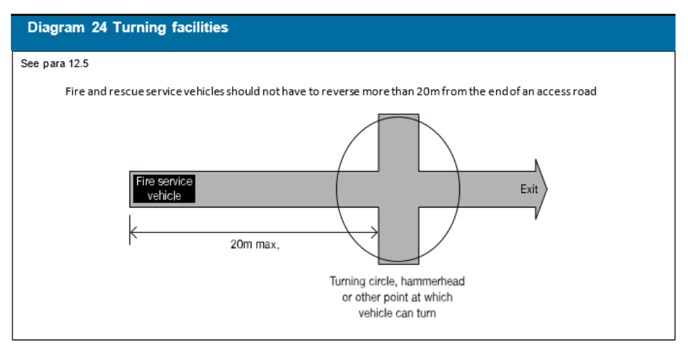
Appendix A Performance of materials, products and structures
#Source page 94
Appendix A
Appendix A Performance of materials, products and structures
Introduction
1.Much of the guidance in this document is given in terms of performance classifications in relation to British or European Standards. In such cases, it will be necessary to demonstrate that a system or product can meet the relevant performance classification.
This will be achieved if the system or product complies with one of the following:
a.They should be in accordance with a specification or design that has been shown by specific test to be capable of meeting that performance classification.
b.They should have been designed by using relevant design standards in order to meet that performance classification
c.They should have been assessed by applying the relevant test evidence, in lieu of carrying out a specific test, as being capable of meeting that performance classification.
Note: Some products are subject to Classification Without Further Testing (CWFT). For the purposes of this approved document, such products can be considered to have been shown to be capable of meeting a performance specification as per paragraph 1a. above.
2.Any test evidence used to demonstrate the fire performance classification of a product or system should be carefully checked to ensure that it is applicable to the intended use. Small differences in detail, such as fixing method, joints, dimensions, the introduction of insulation materials and air gaps (ventilated or not), can significantly affect the performance.
3.Assessments should not be regarded as a way to avoid a test where one is necessary. They should only be carried out where sufficient relevant test evidence is available. Relevant test evidence is unlikely to be provided by test standards which have different classification criteria.
4.Where it is proposed to assess the classification of a product or system in lieu of carrying out a specific test (as in paragraph 1(b)), this should be done in accordance with the relevant standard for extended application for the test in question and should include details of the test evidence that has been used to support the assessment.
For performance classifications where there is no specific standard for extended application, assessment reports should be produced in accordance with the principles of BS EN 15725:2010 and should include details of the test evidence that has been used to support the assessment. Further information on best practice is provided in the Passive Fire Protection Federation’s:
Page 95
#Source page 95
Appendix A
Guide to undertaking technical assessments of the fire performance of construction products based on fire test evidence 2019.
Note: Regulation 7(2) limits components used in or on the external walls of certain buildings to materials achieving European classification Class A2-s1, d0 or Class A1 (see Section 13). Assessments cannot be used to demonstrate compliance with this requirement
5.Tests and assessments should be carried out by organisations with the necessary expertise. For example, organisations listed as “notified bodies” in accordance with the European Construction Products Regulation or laboratories accredited by UKAS for the relevant test standard can be assumed to have the necessary expertise.
Note: Standard fire tests do not directly measure fire hazard. They measure or assess the response of a material or system to exposure to one or more aspects of fire conditions. Performance in fire tests is only one of a number of factors that should be taken into account.
Fire resistance
6.Factors having a bearing on fire resistance that are considered in this document, are:
a.fire severity;
b.building height; and
c.building occupancy.
7.The standards of fire resistance given are based on assumptions about the severity of fires and the consequences should an element fail. Fire severity is estimated in very broad terms from the use of the building (its purpose group), on the assumption that the building contents (which constitute the fire load) are similar for buildings in the same use.
A number of factors affect the standard of fire resistance specified. These are:
a.the amount of combustible material per unit of floor area in various types of building (the fire load density);
b.the height of the top floor above ground, which affects the ease of escape and of firefighting operations, and the consequences should large scale collapse occur;
c.occupancy type, which reflects the ease with which the building can be evacuated quickly;
d.whether there are basements, because the lack of an external wall through which to vent heat and smoke may increase heat build-up and thus affect the duration of a fire, as well as complicating firefighting; and
e.whether the building is of single storey construction (where escape is direct and structural failure is unlikely to precede evacuation).
Page 96
#Source page 96
Appendix A
Because the use of buildings may change, a precise estimate of fire severity based on the fire load due to a particular use may be misleading. Therefore, if a fire engineering approach of this kind is adopted, the likelihood that the fire load may change in the future needs to be considered.
8.Performance in terms of the fire resistance to be met by elements of structure, doors and other forms of construction is determined by reference to either:
a. (National tests) BS 476 Fire tests on building materials and structures, Parts 20-24:1987, i.e. Part 20 Method for determination of the fire resistance of elements of construction (general principles), Part 21 Methods for determination of the fire resistance of loadbearing elements of construction, Part 22 Methods for determination of the fire resistance of non-loadbearing elements of construction, Part 23 Methods for determination of the contribution of components to the fire resistance of a structure, and Part 24 Method for determination of the fire resistance of ventilation ducts (or to BS476-8:1972 in respect of items tested or assessed prior to 1 January 1988); or b. (European tests) Commission Decision 2000/367/EC of 3 May 2000 implementing Council Directive 89/106/EEC as regards the classification of the resistance to fire performance of construction products, construction works and parts thereof.
Note: The latest version of any standard may be used provided that it continues to address the relevant requirements of the Regulations.
All products are classified in accordance with BS EN 13501-2:2007 Fire classification of construction products and building elements. Classification using data from fire resistance tests, excluding ventilation services (excluding products for use in ventilation systems).
BS EN 13501-3:2005 Fire classification of construction products and building elements. Classification using data from fire resistance tests on products and elements used in building service installations: fire resisting ducts and fire dampers (other than smoke control systems).
BS EN 13501-4:2007, Fire classification of construction products and building elements, Part 4 – Classification using data from fire resistance tests on smoke control systems.
The relevant European test methods under BS EN 1364, 1365, 1366 and 1634 are listed in Appendix F.
Page 97
#Source page 97
Appendix A
Table A1 gives the specific requirements for each element in terms of one or more of the following performance criteria:
a.resistance to collapse (loadbearing capacity), which applies to loadbearing elements only, denoted R in the European classification of the resistance to fire performance;
b.resistance to fire penetration (integrity), denoted E in the European classification of the resistance to fire performance; and
c.resistance to the transfer of excessive heat (insulation), denoted I in the European classification of the resistance to fire performance.
Table A2 sets out the minimum periods of fire resistance for elements of structure.
Table A3 sets out criteria appropriate to the suspended ceilings that can be accepted as contributing to the fire resistance of a floor.
Table A4 sets out limitations on the use of uninsulated fire-resisting glazed elements. These limitations do not apply to the use of insulated fire-resisting glazed elements.
Information on tested elements is frequently given in literature available from manufacturers and trade associations. Information on tests on fire-resisting elements is also given in such publications as: Association for Specialist Fire Protection Yellow Book – Fire protection for structural steel in buildings, 4th edition. See Appendix F.
Roofs
9.Performance in terms of the resistance of roofs to external fire exposure is determined by reference to either:
a. (National tests) BS 476-3:2004 External fire exposure roof tests; or b. (European tests) Commission Decision 2005/823/EC amending Decision 2001/671/ EC Establishing a classification system for the external fire performance of roofs and roof coverings.
Constructions are classified within the National system by two letters in the range A-D, with an AA designation being the best. The first letter indicates the time to penetration; the second letter a measure of the spread of flame.
Constructions are classified within the European system as BROOF (t4), CROOF (t4), DROOF (t4), E ROOF (t4) or FROOF (t4) (with B ROOF (t4) being the highest performance and FROOF (t4) being the lowest) in accordance with BS EN 13501-5:2005 Fire classification of construction products and building elements – Classification using data from external fire exposure to roof tests.
Page 98
#Source page 98
Appendix A
BS EN 13501-5 refers to four separate tests. The suffix (t4) used above indicates that Test 4 is to be used for the purposes of this Approved Document.
Some roof covering products (and/or materials) can be considered to fulfil all of the requirements for the performance characteristic “exter nal fire performance” without the need for testing, subject to any national provisions on the design and execution of works being fulfilled. These roof covering products are listed in Commission Decision 2000/553/EC of 6th September 2000 implementing Council Directive 89/106/EEC as regards the external fire performance of roof coverings.
In some circumstances roofs, or parts of roofs, may need to be fire-resisting, for example if used as an escape route or if the roof performs the function of a floor. Such circumstances are covered in Sections 3, 5 and 7.
Table A5 gives notional designations of some generic roof coverings.
Reaction to fire
10.Performance in terms of reaction to fire to be met by construction products is determined by Commission Decision 200/147/EC of 8 February 2000 implementing Council Directive 89/106/EEC as regards the classification of the reaction to fire performance of construction products.
All products, excluding floorings, are classified as †A1, A2, B, C, D, E or F (with class A1 being the highest performance and F being the lowest) in accordance with BS EN 13501-1:2002 Fire classification of construction products and building elements, Part 1 – Classification using data from reaction to fire tests.
†
The classes of reaction to fire performance of A2, B, C, D and E are accompanied by additional classifications related to the production of smoke (s1, s2, s3) and/or flaming droplets/particles (d0, d1, d2).
The relevant European test methods are specified as follows:
•BS EN ISO 1182:2002 Reaction to fire tests for building products – Non- combustibility test
•BS EN ISO 1716:2002 Reaction to fire tests for building products – Determination of the gross calorific value
•BS EN 13823:2002 Reaction to fire tests for building products – Building products excluding floorings exposed to the thermal attack by a single burning item
•BS EN ISO 11925-2:2002 Reaction to fire tests for building products, Part 2 – Ignitability when subjected to direct impingement of a flame.
•BS EN 13238:2001 Reaction to fire tests for building products – conditioning procedures and general rules for selection of substrates.
Page 99
#Source page 99
Appendix A
Non-combustible materials
11.Non-combustible materials are defined in Table A6 either as listed products, or in terms of performance:
a.(National classes) when tested to BS 476-4:1970 Fire tests on building materials and structures – Non-combustibility test for materials or BS 476- 11:1982 Fire tests on building materials and structures – Method for assessing the heat emission from building materials.
b.(European classes) when classified as class A1 in accordance with BS EN 13501-1:2002 Fire classification of construction products and building elements. Classification using data from reaction to fire tests when tested to BS EN ISO 1182:2002 Reaction to fire tests for building products – Non- combustibility test and BS EN ISO 1716:2002 Reaction to fire tests for building products – Determination of the gross calorific value.
Table A6 identifies non-combustible products and materials, and lists circumstances where their use is necessary.
Materials of limited combustibility
12.Materials of limited combustibility are defined in Table A7:
a. (National classes) by reference to the method specified in BS 476-11:1982;
b. (European classes) in terms of performance when classified as class A2-s3, d2 in accordance with BS EN 13501-1:2002 Fire classification of construction products and building elements. Classification using data from reaction to fire tests when tested to BS EN ISO 1182:2002 Reaction to fire tests for building products – Non-combustibility test or BS EN ISO 1716:2002 Reaction to fire tests for building products – Determination of the gross calorific value and BS EN 13823:2002 Reaction to fire tests for building products – Building products excluding floorings exposed to the thermal attack by a single burning item.
Table A7 also includes composite products (such as plasterboard) which are considered acceptable, and where these are exposed as linings they should also meet any appropriate flame spread rating.
Internal linings
13.Flame spread over wall or ceiling surfaces is controlled by providing for the lining materials or products to meet given performance levels in tests appropriate to the materials or products involved.
14.Under the National classifications, lining systems which can be effectively tested for ‘surface spread of flame’ are rated for performance by reference to the method specified in BS 476-7:1997 (or 1987 or 1971) Fire tests on building materials and structures. Method of test to determine the classification of the surface spread of flame of products under which materials or products are classified 1, 2, 3 or 4 with Class 1 being the highest.
Page 100
#Source page 100
Appendix A
Under the European classifications, lining systems are classified in accordance with BS EN 13501-1:2002 Fire classification of construction products and building elements, Part 1 – Classification using data from reaction to fire tests. Materials or products are classified as A1, A2, B, C, D, E or F, with A1 being the highest. When a classification includes ‘s3, d2’, it means that there is no limit set for smoke production and/or flaming droplets/particles.
15.To restrict the use of materials which ignite easily, which have a high rate of heat release and/ or which reduce the time to flashover, maximum acceptable ‘fire propagation’ indices are specified, where the National test methods are being followed. These are determined by reference to the method specified in BS 476- 6:1989 or 1981. Index of performance (I) relates to the overall test performance, whereas sub-index (i1) is derived from the first three minutes of test.
16.The highest National product performance classification for lining materials is Class 0. This is achieved if a material or the surface of a composite product is either:
a.composed throughout of materials of limited combustibility; or
b.a Class 1 material which has a fire propagation index (I) of not more than 12 and sub-index (i1) of not more than 6.
Note: Class 0 is not a classification identified in any British Standard test.
17.Composite products defined as materials of limited combustibility (see paragraph 12 and Table A7) should in addition comply with the test requirement appropriate to any surface rating specified in the guidance on requirements B2, B3 and B4.
18.The notional performance ratings of certain widely used generic materials or products are listed in Table A8 in terms of their performance in the traditional lining tests BS 476-6:1989 and BS 476-7:1997 or in accordance with BS EN 13501- 1:2002.
19.Results of tests on proprietary materials are frequently given in literature available from manufacturers and trade associations.
Any reference used to substantiate the surface spread of flame rating of a material or product should be carefully checked to ensure that it is suitable, adequate and applicable to the construction to be used. Small differences in detail, such as thickness, substrate, colour, form, fixings, adhesive etc, may significantly affect the rating.
Page 101
#Source page 101
Appendix A
Thermoplastic Materials
20.A thermoplastic material means any synthetic polymeric material which has a softening point below 200ºC if tested to BS EN ISO 306:2004 method A120 Plastics – Thermoplastic materials – Determination of Vicat softening temperature. Specimens for this test may be fabricated from the original polymer where the thickness of material of the end product is less than 2.5mm.
21.A thermoplastic material in isolation cannot be assumed to protect a substrate when used as a lining to a wall or ceiling. The surface rating of both products must therefore meet the required classification. If, however, the thermoplastic material is fully bonded to a non- thermoplastic substrate, then only the surface rating of the composite will need to comply.
22.Concessions are made for thermoplastic materials used for window glazing, rooflights, and lighting diffusers within suspended ceilings, which may not comply with the criteria specified in paragraphs 14 to 19. They are described in the guidance on requirements B2 and B4.
23.For the purposes of the requirements B2 and B4 thermoplastic materials should either be used according to their classificat ion 0-3, under the BS 476-6:1989 and BS 476-7:1997 tests as described in paragraphs 14 to 19, (if they have such a rating), or they may be classified TP(a) rigid, TP(a) flexible, or TP(b) according to the following methods:
TP(a) rigid:
i. Rigid solid pvc sheet;
ii. Solid (as distinct from double- or multiple-skin) polycarbonate sheet at least 3mm thick;
iii Multi-skinned rigid sheet made from unplasticised pvc or polycarbonate which has a Class 1 rating when tested to BS 476-7:1997 or 1971 or 1987; and Any other rigid thermoplastic product, a specimen of which (at the thickness of the product as put on the market), when tested to BS 2782:1970 as amended in 1974: Method 508A Rate of burning (Laboratory method), performs so that the test flame extinguishes before the first mark and the duration of flaming or afterglow does not exceed five seconds following removal of the burner.
TP(a) flexible: Flexible products not more than 1mm thick which comply with the Type C requirements of BS 5867-2:1980 Specification for fabrics for curtains and drapes – Flammability requirements when tested to BS 5438:1989 Methods of test for flammability of textile fabrics when subjected to a small igniting flame applied to the face or bottom edge of vertically oriented specimens, Test 2, with the flame applied to the surface of the specimens for 5, 15, 20 and 30 seconds respectively, but excluding the cleansing procedure; and
TP(b):
#Source page 102
Appendix A
TP(b):
i. Rigid solid polycarbonate sheet products less than 3mm thick, or multiple- skin polycarbonate sheet products which do not qualify as TP(a) by test; or ii. Other products which, when a specimen of the material between 1.5 and 3mm thick is tested in accordance with BS2782:1970, as amended in 1974: Method 508A, has a rate of burning which does not exceed 50mm/minute.
Note: If it is not possible to cut or machine a 3mm-thick specimen from the product then a 3mm test specimen can be moulded from the same material as that used for the manufacture of the product.
Note: Currently, no new guidance is possible on the assessment or classification of thermoplastic materials under the European system since there is no generally accepted European test procedure and supporting comparative data.
Fire test methods
24.A guide to the various test methods in BS 476 and BS 2782 is given in PD 6520
Guide to fire test methods for building materials and elements of construction
(available from the British Standards Institution).
A guide to the development and presentation of fire tests and their use in hazard assessment is given in BS 6336:1998 Guide to development and presentation of fire tests and their use in hazard assessment.
Page 103
#Source page 103
Appendix A
| Part of building | Minimum provisions when tested to the relevant part of BS 476 (1) (minutes) | Minimum provisions when tested to the relevant European standard (minutes)(9) | Method of exposure | ||
|---|---|---|---|---|---|
| Loadbearing (2) capacity | Integrity | Insulation | |||
| 1. Structural frame, beam or column | See Table A2 | Not applicable | Not applicable | R see Table A2 | Exposed faces |
| 2 .Loadbearing wall (which is not also a wall described in any of the following items). | See Table A2 | Not applicable | Not applicable | R see Table A2 | Each side separately |
| 3. Floor(3) a. In upper storey of 2- storey dwellinghouse (but not over garage or basement); b. Any other floor – including compartment floors. | 30 | 15 | 15 | R 30 and REI 15 | From underside |
| See Table A2 | See Table A2 | See Table A2 | REI see Table A2 | From underside | |
| 4. Roof Any part forming an escape route; | 30 | 30 | 30 | REI 30 | From underside (4) |
| 5. External walls a. any part less than 1000mm from any point on the relevant boundary; b. any part 1000mm or more from the relevant boundary (5); c. any part adjacent to an external escape route (see paragraph 3.10 and 3.15 and Diagram 7). | See Table A2 | See Table A2 | See Table A2 | REI see Table A2 | Each side separately |
| See Table A2 | See Table A2 | 15 | RE see Table A2 and REI 15 | From inside the building | |
| 30 | 30 | No provision (6)(7) | RE 30 | From inside the building |
Page 104
#Source page 104
Appendix A
| Part of building | Minimum provisions when tested to the relevant part of BS 476 (1) (minutes) | Minimum provisions when tested to the relevant European standard (9) (minutes) | Method of exposure | ||
|---|---|---|---|---|---|
| Loadbearing capacity (2) | Integrity | Insulation | |||
| 6. Compartment walls (other than in item 8) | See Table A2 | See Table A2 | See Table A2 | REI see Table A2 | Each side separately |
| 7. Enclosure (which does not form part of a compartment wall or a protected shaft) to a: a. protected stairway; b. lift shaft. | |||||
| 30 | 30 | (8) 30 | (8) REI 30 | Each side separately | |
| 30 | 30 | 30 | REI 30 | Each side separately | |
| 8. Wall or floor separating an attached or integral garage from a dwellinghouse 30 attached or integral garage fa dwellinghouse | 30 | 30 | (8) 30 | (8) REI 30 | From garage side |
| 9. Fire-resisting construction: in dwellinghouses not described elsewhere | 30 | 30 | (8) 30 | (8) REI 30 | |
| 10. Cavity barrier | Not applicable | 30 | 15 | E30 and EI15 | Each side separately |
| 11. Ceiling Described in paragraph 3.14. Diagram 6 | Not applicable | 30 | 30 | EI 30 | From underside |
| 12. Duct described in paragraph 7.8e | Not applicable | 30 | No provision | E 30 | From outside |
| 13. Casing around a drainage system described in paragraph 8.8. Diagram | Not applicable | 30 | No provision | E 30 | From outside |
Page 105
#Source page 105
Appendix A
| Part of building | Minimum provisions when tested to the relevant part of BS 476 (1) (minutes) | Minimum provisions when tested to the relevant European standard (minutes)(9) | Method of exposure | ||
|---|---|---|---|---|---|
| Loadbearing capacity (2) | Integrity | Insulation | |||
| 14. Flue walls described in paragraph 8.11. Diagram 16 | Not applicable | Half the period specified in Table A2 for the compartment wall/floor | Half the period specified in Table A2 for the compartment wall/floor | EI half the period specified in Table A2 for the compartment wall/floor | From outside |
| 15. Construction described in Note (a) to paragraph 11.9 | Not applicable | 30 | 30 | EI 30 | From underside |
| 16. Fire doors | See Table B1 | See Table B1 |
Notes:
1.Part 21 for loadbearing elements, Part 22 for non-loadbearing elements, Part 23 for fire-protecting suspended ceilings, and Part 24 for ventilation ducts. BS 476- 8 results are acceptable for items tested or assessed before 1 January 1988.
2.Applies to loadbearing elements only (see B3.ii and Appendix E).
3.Guidance on increasing the fire resistance of existing timber floors is given in BRE Digest 208 Increasing the fire resistance of existing timber floors (BRE 1988).
4.A suspended ceiling should only be relied on to contribute to the fire resistance of the floor if the ceiling meets the appropriate provisions given in Table A3.
5.The guidance in Section 10 allows such walls to contain areas which need not be fire-resisting (unprotected areas).
6.Unless needed as part of a wall in item 5a or 5b.
7.Except for any limitations on glazed elements given in Table A4.
8.See Table A4 for permitted extent of uninsulated glazed elements.
9.The National classifications do not automatically equate with the equivalent classifications in the European column, therefore products cannot typically assume a European class unless they have been tested accordingly. ‘R’ is the European classification of the resistance to fire performance in respect of loadbearing capacity; ‘E’ is the European classification of the resistance to fire performance in respect of integrity; and ‘I’ is the European classification of the resistance to fire performance in respect of insulation.
Page 106
#Source page 106
Appendix A
| Minimum periods (minutes) for elements of structure in a: | ||
|---|---|---|
| Basement storey (1) including floor over | Ground or upper storey | |
| Height (m) of top floor above ground | ||
| Not more than 5 | More than 5 | |
| 30(2) | 30(2) | 60(3) |
Notes: Modifications referred to in Table A2:
1.The floor over a basement (or if there is more than one basement, the floor over the topmost basement) should meet the provisions for the ground and upper storeys if that period is higher.
2.Increased to a minimum of 60 minutes for compartment walls separating buildings.
3.30 minutes in the case of three storey dwellinghouses, increased to 60 minutes minimum for compartment walls separating buildings.
4.Refer to Table A1 for the specific provisions of test.
Application of the fire resistance standards in table A2:
a.Where one element of structure supports or carries or gives stability to another, the fire resistance of the supporting element should be no less than the minimum period of fire resistance for the other element (whether that other element is loadbearing or not).
There are circumstances where it may be reasonable to vary this principle, for example:
i.where the supporting structure is in the open air, and is not likely to be affected by the fire in the building; or
ii.where the supporting structure is in a different compartment, with a fire- separating element (which has the higher standard of fire resistance) between the supporting and the separated structure; or
iii.where a plant room on the roof needs a higher fire resistance than the elements of structure supporting it.
b.Where an element of structure forms part of more than one building or compartment, that element should be constructed to the standard of the greater of the relevant provisions.
c.Although most elements of structure in a single storey building may not need fire resistance (see the guidance on requirement B3, paragraph 5.4(a)), fire resistance will be needed if the element:
i.is part of (or supports) an external wall and there is provision in the guidance on requirement B4 to limit the extent of openings and other unprotected areas in the wall; or
ii.is part of (or supports) a compartment wall, including a wall common to two or more buildings, or a wall between a dwellinghouse and an attached or integral garage; or
iii.supports a gallery.
Page 107
#Source page 107
Appendix A
For the purposes of this paragraph, the ground storey of a building which has one or more basement storeys and no upper storeys, may be considered as a single-storey building. The fire resistance of the basement storeys should be that appropriate to basements.
Table A3 Limitations on fire-protecting suspended ceilings (see Table A1, Note 4)
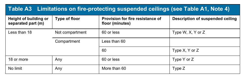
Notes:
1.Ceiling type and description (the change from Types A-D to Types W-Z is to avoid confusion with Classes A-D (European)):
W. Surface of ceiling exposed to the cavity should be Class 0 or Class 1 (National) or Class C-s3, d2 or better (European).
X. Surface of ceiling exposed to the cavity should be Class 0 (National) or Class B-s3, d2 or better (European).
Y. Surface of ceiling exposed to the cavity should be Class 0 (National) or Class B-s3, d2 or better (European). Ceiling should not contain easily openable access panels.
Z. Ceiling should be of a material of limited combustibility (National) or of Class A2-s3, d2 or better (European) and not contain easily openable access panels. Any insulation above the ceiling should be of a material of limited combustibility (National) or Class A2-s3, d2 or better (European).
2.Any access panels provided in fire protecting suspended ceilings of type Y or Z should be secured in position by releasing devices or screw fixings, and they should be shown to have been tested in the ceiling assembly in which they are incorporated.
3.The National classifications do not automatically equate with the equivalent European classifications, therefore products cannot typically assume a European class unless they have been tested accordingly. When a classification includes ‘s3, d2’, this means that there is no limit set for smoke production and/or flaming droplets/particles.
Page 108
#Source page 108
Appendix A
Table A4 Limitations on the use of uninsulated glazed elements on escape
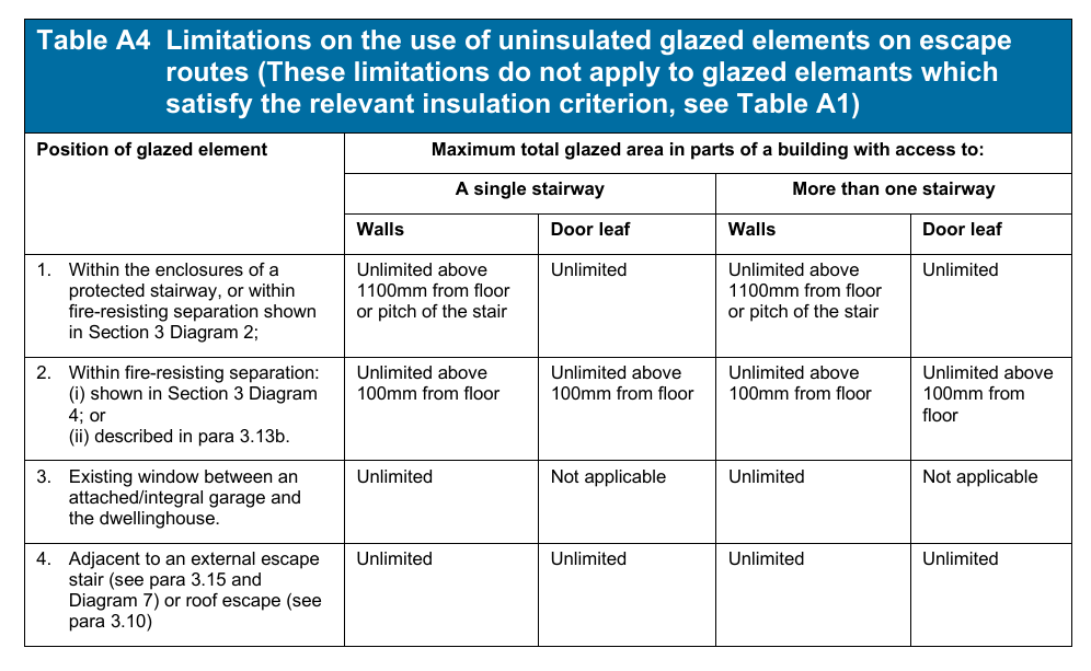
Notes:
1.The 100mm limit is intended to reduce the risk of fire spread from a floor covering.
2.Fire-resisting glass should be marked with the manufacturer and product name.
3.Good guidance can be found in A guide to best practice in the specification and use of fire-resistant glazed systems published by the Glass and Glazing Federation.
Page 109
#Source page 109
Appendix A
| Part i: Pitched roofs covered with slates or tiles | ||||
|---|---|---|---|---|
| Covering material | Supporting structure | Designation | ||
| 1. Natural slates 2. Fibre reinforced cement slates 3. Clay tiles 4. Concrete tiles | Timber rafters with or without underfelt, sarking, boarding, woodwool slabs, compressed straw slabs, plywood, wood chipboard, or fibre insulating board | AA (National class) or B ROOF (t4) (European class) | ||
| Note: Although the Table does not include guidance for roofs covered with bitumen felt, it should be noted that there is a wide range of materials on the market and information on specific products is readily available from manufactur ers. | ||||
| Part ii: Pitched roofs covered with self-supporting sheet | ||||
| Roof covering material | Construction | Supporting structure | Designation | |
| 1. Profiled sheet of galvanised steel, aluminium, fibre reinforced cement, or pre- painted (coil coated) steel or aluminium witha pvc or pvf2 coating | Single skin without underlay, or with underlay or plasterboard, fibre insulating board, or woodwool slab | Structure of timber, steel or concrete | AA (National class) or B ROOF (t4) (European class) | |
| 2. Profiled sheet of galvanised steel, aluminium, fibre reinforced cement, orpre-painted (coil coated) steel or aluminium with a pvc or pvf2 coating | Double skin without interlayer, or with interlayer of resin bonded glass fibre, mineral wool slab, polystyrene, or polyurethane | Structure of timber, steel or concrete | AA (National class) or B ROOF (t4) (European class) | |
| Part iii. Flat roofs covered with bitumen felt | ||||
| A flat roof comprising bitumen felt should (irrespective of the felt specification) be deemed to be of designation AA (National class) or B ROOF (t4) (European class) if the felt is laid on a deck constructed of 6mm plywood, 12.5mm wood chipboard, 16mm (finished) plain edged timber boarding, compressed straw slab, screeded wood wool slab, profiled fibre reinforced cement or steel deck (single or double skin) with or without fibre insulating board overlay, profiled aluminium deck (single or double skin) with or without fibre insulating board overlay, or concrete or clay pot slab (insitu or pre cast), and has a surface finish of: a. bitumen-bedded stone chippings covering the whole surface to a depth of at least 12.5mm; b. bitumen-bedded tiles of a non-combustible material; c. sand and cement screed; or d. macadam. |
Page 110
#Source page 110
Appendix A
| Part iv. Pitched or flat roofs covered with fully supported material | ||
|---|---|---|
| Covering material | Supporting structure | Designation |
| 1. Aluminium sheet 2. Copper sheet 3. Zinc sheet 4. Lead sheet 5. Mastic asphalt 6. Vitreous enamelled steel 7. Lead/tin alloy coated steel sheet 8. Zinc/aluminium alloy coated steel sheet 9. Pre-painted (coil coated) steel sheet including liquid- applied pvc coatings | timber joists and: tongued and grooved boarding, or plain edged boarding | AA* (National class) or B ROOF (t4) (European class) |
| steel or timber joists with deck of: woodwool slabs, compressed straw slab, wood chipboard, fibre insulating board, or 9.5mm plywood | AA (National class) or B ROOF (t4) (European class) | |
| non-combustible deck of steel, aluminium, or fibre cement (with or without insulation) | AA (National class) or BROOF (t4) (European class) | |
| Notes: * Lead sheet supported by timber joists and plain edged boarding should be regarded as having a BA designation and is deemed to be designated class CROOF(t4) (European class). The National classifications do not automatically equate with the equivalent classifications in the European column, therefore products cannot typically assume a European class unless they have been tested accordingly. |
Page 111
#Source page 111
Appendix A
| References in AD B guidance to situations where such materials should be used | Definitions of non-combustible materials | |
|---|---|---|
| National class | European class | |
| 1. Pipes meeting the provisions in the guidance to B3, Table 3. 2. Flue walls meeting the provisions in the guidance to B3, Diagram 16. | a. Any material which when tested to BS 476- 11:1982 does not flame nor cause any rise in temperature on either the centre (specimen) or furnace thermocouples. b. Totally inorganic materials such as concrete, fired clay, ceramics, metals, plaster and masonry containing not more than 1% by weight or volume of organic material. (Use in buildings of combustible metals such as magnesium/aluminium alloys should be assessed in each individual case). c. Concrete bricks or blocks meeting BS EN 771-3:2003 d. Products classified as non-combustible under BS 476-4:1970 | a. Any material classified as class A1 in accordance with BS EN 13501-1:2002 Fire classification of construction products and building elements. Classification using data from reaction to fire tests. b. Products made from one or more of the materials considered as Class A1 without the need for testing as defined in Commission Decision 2003/424/EC of 6th June 2003 amending Decision ,96/603/EC establishing the list of products belonging to Classes A1 “No contribution to fire” provided for in the Decision 94/611/EC implementing Article 20 of the Council Directive ,89/106/EEC on construction products. None of the materials shall contain more than 1% by weight or volume (whichever is the more onerous) of homogeneously distributed organic material |
| Note: The National classifications do not automatically equate with the equivalent classifications in the European column, therefore products cannot typically assume a European class unless they have been tested accordingly. |
Page 112
#Source page 112
Appendix A
Table A7 Use and definitions of materials of limited combustibility
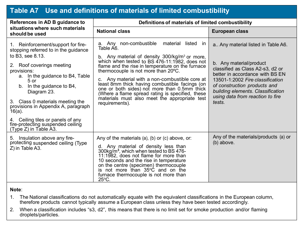
Page 113
#Source page 113
Appendix A
| Rating | Material or product |
|---|---|
| Class 0 (National) | 1. Any non-combustible material or material of limited combustibility. (composite products listed in Table A7 must meet test requirements given in Appendix A, paragraph 16(b)). 2. Brickwork, blockwork, concrete and ceramic tiles. 3. Plasterboard (painted or not with a PVC facing not more than 0.5mm thick) with or without an air gap or fibrous or cellular insulating material behind. 4 Woodwool cement slabs. 5. Mineral fibre tiles or sheets with cement or resin binding. |
| Class 3 (National) | 6. Timber or plywood with a density more than 400kg/m ³, painted or unpainted. 7. Wood particle board or hardboard, either untreated or painted. 8. Standard glass reinforced polyesters. |
| Class A1 (European) | 9. Any material that achieves this class or is defined as ‘classified without further test’ in a published Commission Decision. |
| Class A2-s3, d2 (European) | 10. Any material that achieves this class or is defined as ‘classified without further test’ in a published Commission Decision. |
| Class B-s3, d2 (European) | 11. Any material that achieves this class or is defined as ‘classified without further test ’ in a published Commission Decision. |
| Class C-s3, d2 (European) | 12. Any material that achieves this class or is defined as ‘classified without further test’ in a published Commission Decision. |
| Class D-s3, d2 (European) | 13. Any material that achieves this class or is defined as ‘classified without further test’ in a published Commission Decision. |
Notes (National):
1.Materials and products listed under Class 0 also meet Class 1.
2.Timber products listed under Class 3 can be brought up to Class 1 with appropriate proprietary treatments.
3.The following materials and products may achieve the ratings listed below. However, as the properties of different products with the same generic description vary, the ratings of these materials/products should be substantiated by test evidence.
Class 0 – aluminium faced fibre insulating board, flame retardant decorative laminates on a calcium silicate board, thick polycarbonate sheet, phenolic sheet and UPVC. Class 1 – phenolic or melamine laminates on a calcium silicate substrate and flame-retardant decorative laminates on a combustible substrate.
Notes (European): For the purposes of the Building Regulations:
1.Materials and products listed under Class A1 also meet Classes A2-s3, d2, B-s3, d2, C-s3, d2 and D-s3, d2.
2.Materials and products listed under Class A2-s3, d2 also meet Classes B-s3, d2, C-s3, d2 and D-s3, d2.
3.Materials and products listed under Class B-s3, d2 also meet Classes C-s3, d2 and D-s3, d2.
4.Materials and products listed under Class C-s3, d2 also meet Class D-s3, d2.
5.The performance of timber products listed under Class D-s3, d2 can be improved with appropriate proprietary treatments.
6.Materials covered by the CWFT process (classification without further testing) can be found by accessing the
European Commission’s website via the link on the CLG website www.communities.gov.uk
7.The national classifications do not automatically equate with the equivalent classifications in the European column, therefore products cannot typically assume a European class unless they have been tested accordingly.
8.When a classification includes ‘s3, d2’, this means that there is no limit set for smoke production and/or flaming droplets/particles.
Appendix B Fire doors
#Source page 114
Appendix B
Appendix B Fire doors
1.All fire doors should have the appropriate performance given in Table B1 either:
a.by their performance under test to BS 476-22 Fire tests on building materials and structures. Methods for determination of the fire resistance of non- loadbearing elements of construction, in terms of integrity for a period of minutes, e.g. FD30. A suffix (S) is added for doors where restricted smoke leakage at ambient temperatures is needed; or
b.as determined with reference to Commission Decision 2000/367/EC of 3 May 2000 implementing Council Directive 89/106/EEC as regards the classification of the resistance to fire performance of construction products, construction works and parts thereof. All fire doors should be classified in accordance with BS EN 13501-2:2003 Fire classification of construction products and building elements. Classification using data from fire resistance tests (excluding products for use in ventilation systems). They are tested to the relevant European method from the following:
BS EN 1634-1:2008
Fire resistance and smoke control tests for door and shutter assemblies, openable windows and elements of building hardware. Fire resistance tests for doors, shutters and openable windows;
BS EN 1634-2:2008
Fire resistance and smoke control tests for door and shutter assemblies, openable windows and elements of building hardware. Fire resistance characterisation test for elements of building hardware;
BS EN 1634-3:2004
Fire resistance and smoke control tests for door and shutter assemblies, openable windows and elements of building hardware. Smoke control test for door and shutter assemblies.
The requirement (in either case) is for test exposure from each side of the door separately.
Any test evidence used to substantiate the fire resistance rating of a door or shutter should be carefully checked to ensure that it adequately demonstrates compliance and is applicable to the adequately complete installed assembly. Small differences in detail (such as glazing apertures, intumescent strips, door frames and ironmongery etc.) may significantly affect the rating.
Page 115
#Source page 115
Appendix B
The requirement (in either case) is for test exposure from each side of the door separately, except in the case of lift doors which are tested from the landing side only.
Note 1: Both BS 476-22 and BS EN 1634-1 acknowledge that it may not always be necessary to carry out tests from both sides of a door set. Clause 13.4 of EN 1634-1 states when it may be appropriate to test on one side. Annex C of the guidance sets out the rationale for these rules and specifically excludes composite doors by stating that:
“Door sets made from other (i.e. not wood or metal) or composite materials are specifically excluded from this annex as there is not sufficient evidence of their behaviour in fire to be able to provide guidance on the weakest side against fire attack.”
Clause 13.4 of BS EN 1634-1 should therefore be followed when determining whether a test should be carried out from both sides of a door set regardless of whether it is being classified to BS 476-22 or BS EN 1634-1.
Note 2: The latest version of any standard may be used provided that it continues to address the relevant requirements of the Regulations.
Note 3: Until such time that the relevant harmonised product standards are published, for the purposes of meeting the Building Regulations, products tested in accordance with BS EN 1634-1 (with or without pre-fire test mechanical conditioning) will be deemed to have satisfied the provisions provided that they achieve the minimum fire resistance in terms of integrity, as detailed in Table B1.
2.Fire doors serving an attached or integral garage should be fitted with a self- closing device.
3.Unless shown to be satisfactory when tested as part of a fire door assembly, the essential components of any hinge on which a fire door is hung should be made entirely from materials having a melting point of at least 800ºC.
4.Tables A1 and A2 set out the minimum periods of fire resistance for the elements of structure to which performance of some doors is linked. Table A4 sets out limitations on the use of uninsulated glazing in fire doors.
5.BS 8214:1990 gives recommendations for the specification, design, construction, installation and maintenance of fire doors constructed with non-metallic door leaves.
•Guidance on timber fire-resisting doorsets, in relation to the new European test standard, may be found in Timber fire-resisting doorsets: maintaining performance under the new European test standard published by TRADA (Timber Research and Development Association). Guidance for metal doors is given in Code of practice for fire-resisting metal doorsets published by the DSMA (Door and Shutter Manufacturers’ Association) in 1999.
6.Hardware used on fire doors can significantly affect performance in fire. Notwithstanding the guidance in this Approved Document guidance is available in Hardware for fire and escape doors published by the Builders’ Hardware Industry Federation.
Page 116
#Source page 116
Appendix B
| Position of door | Minimum fire resistance of door in terms of integrity (minutes) when tested to BS 476- 22:1987 (1) | Minimum fire resistance of door in terms of integrity (minutes) when tested to the relevant European standard (3) |
|---|---|---|
| 1. Any door: a. Within a cavity barrier b. Between a dwellinghouse and a garage c. Forming part of the enclosures to a protected stairway in a single family dwellinghouse d. Within any other fire-resisting construction in a dwellinghouse not described elsewhere in this table | FD 30 FD 30s (2) FD 20 FD 20 | E30 E30Sa (2) E20 E20 |
Notes:
1.To BS 476-22:1987 (or BS 476-8:1972 subject to paragraph 8 in Appendix A).
2.Unless pressurization techniques complying with BS EN 12101-6:2005 Code of practice for smoke control using pressure differentials are used, these doors should also either:
3
(a)have a leakage rate not exceeding 3m /m/hour (head and jambs only) when tested at 25 Pa under BS 476 Fire tests on building materials and structures, Section
31.1Methods for measuring smoke penetration through doorsets and shutter assemblies, Method of measurement under ambient temperature conditions; or
(b)meet the additional classification requirement of Sa when tested to BS EN 1634-
3:2001 Fire resistance tests for door and shutter assemblies, Part 3 – Smoke control doors.
3.The National classifications do not automatically equate with the equivalent classifications in the European column, therefore products cannot typically assume a European class unless they have been tested accordingly.
Appendix C Methods of measurement
#Source page 117
Appendix C
Appendix C Methods of measurement
1.Some form of measurement is an integral part of many of the provisions in this document. Diagram C1 shows how the height of the top storey should be measured.
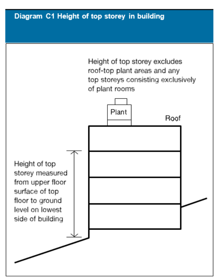
Appendix D Purpose groups
#Source page 118
Appendix D
Appendix D Purpose groups
1.Many of the provisions in this document are related to the use of the building. The use classifications are termed purpose groups and represent different levels of hazard. They can apply to a whole building, or (where a building is compartmented) to a compartment in the building, and the relevant purpose group should be taken from the main use of the building or compartment.
2.Table D1 sets out the purpose group classification.
Note: This is only of relevance to this Approved Document.
| Title | Group | Purpose for which the building or compartment of a building is intended to be used |
|---|---|---|
| Residential (dwellings) | 1(a)* † 1(b) † 1(c) | Flat. |
| Dwellinghouse which contains a habitable storey with a floor level which is more than 4.5m above ground level. | ||
| Dwellinghouse which does not contain a habitable storey with a floor level which is more than 4.5m above ground level. | ||
| Residential (Institutional) (Other) | 2(a) 2(b) | Hospital, home, school or other similar establishment used as living accommodation for, or for the treatment, care or maintenance of persons suffering from disabilities due to illness or old age or other physical or mental incapacity, or under the age of 5 years, or place of lawful detention, where such persons sleep on the premises. |
| Hotel, boarding house, residential college, hall of residence, hostel, and any other residential purpose not described above. | ||
| Office | 3 | Offices or premises used for the purpose of administration, clerical work (including writing, book keeping, sorting papers, filing, typing, duplicating, machine calculating, drawing and the editorial preparation of matter for publication, police and fire and rescue service work), handling money (including banking and building society work), and communications (including postal, telegraph and radio communications) or radio, television, film, audio or video recording, or performance (not open to the public) and their control. |
| Shop and commercial | 4 | Shops or premises used for a retail trade or business (including the sale to members of the public of food or drink for immediate consumption and retail by auction, self-selection and over-the-counter wholesale trading, the business of lending books or periodicals for gain and the business of a barber or hairdresser and the rental of storage space to the public) and premises to which the public is invited to deliver or collect goods in connection with their hire repair or other treatment, or (except in the case of repair of motor vehicles) where they themselves may carry out such repairs or other treatments. |
| Assembly and recreation | 5 | Place of assembly, entertainment or recreation; including bingo halls, broadcasting, recording and film studios open to the public, casinos, dance halls; entertainment, conference, exhibition and leisure centres; funfairs and amusement arcades; museums and art galleries; non-residential clubs, theatres, cinemas and concert halls; educational establishments, dancing schools, gymnasia, swimming pool buildings, riding schools, skating rinks, sports pavilions, sports stadia; law courts; churches and other buildings of worship, crematoria; libraries open to the public, non-residential day centres, clinics, health centres and surgeries; passenger stations and termini for air, rail, road or sea travel; public toilets; zoos and menageries. |
| Industrial | 6 | Factories and other premises used for manufacturing, altering, repairing, cleaning, washing, breaking-up, adapting or processing any article; generating power or slaughtering livestock. |
| Storage and other non- residential + | 7(a) | Place for the storage or deposit of goods or materials (other than described under 7(b)) and any building not within any of the Purpose Groups 1 to 6. |
| 7(b) | Car parks designed to admit and accommodate only cars, motorcycles and passenger or light goods vehicles weighing no more than 2500kg gross. |
Page 119
#Source page 119
Appendix D
Table D1 Notes:
This table only applies to Part B.
* Includes live/work units that meet the provisions of paragraph 3.52 of Volume 2.
† Includes any surgeries, consulting rooms, offices or other accommodation, not exceeding 50m² in total, forming part of a dwelling and used by an occupant of the dwelling in a professional or business capacity.
+ A detached garage not more than 40m² in area is included in Purpose Group 1(c); as is a detached open carport of not more than 40m², or a detached building which consists of a garage and open carport where neither the garage nor open carport exceeds 40m² in area.
Appendix E Definitions
#Source page 120
Appendix E
Appendix E Definitions
Note: Except for the items marked * (which are from the Building Regulations), these definitions apply only to Part B.
Access room A room through which the only escape route from an inner room passes.
Accommodation stair A stair, additional to that or those required for escape purposes, provided for the convenience of occupants.
Alternative escape routes Escape routes sufficiently separated by either direction and space, or by fire-resisting construction, to ensure that one is still available should the other be affected by fire.
Note: A second stair, balcony or flat roof which enables a person to reach a place free from danger from fire, is considered an alternative escape route for the purposes of a dwellinghouse.
Alternative exit One of two or more exits, each of which is separate from the other.
Appliance ventilation duct A duct provided to convey combustion air to a gas appliance.
Automatic release mechanism A device which will allow a door held open by it to close automatically in the event of each or any one of the following:
a.detection of smoke by automatic apparatus suitable in nature, quality and location;
b.operation of a hand-operated switch fitted in a suitable position;
c.failure of electricity supply to the device, apparatus or switch;
d.operation of the fire alarm system if any.
Automatic fire suppression System For the purposes of paragraph 2.2 this refers to a system designed and installed in accordance with an appropriate, fully implemented, technical standard such as BS 9251: 2014 or equivalent.
Basement storey A storey with a floor which at some point is more than 1200mm below the highest level of ground adjacent to the outside walls.
Boundary The boundary of the land belonging to the building, or where the land abuts a road, railway, canal or river, the centre line of that road, railway, canal or river (See Diagram 17.)
*Building Any permanent or temporary building but not any other kind of structure or erection. A reference to a building includes a reference to part of a building.
Page 121
#Source page 121
Appendix E
Building Control Body A term used to include both Local Authority Building Control and Approved Inspectors.
Cavity barrier A construction, other than a smoke curtain, provided to close a concealed space against penetration of smoke or flame, or provided to restrict the movement of smoke or flame within such a space.
Ceiling A part of a building which encloses and is exposed overhead in a room, protected shaft or circulation space. (The soffit of a rooflight is included as part of the surface of the ceiling, but not the frame. An upstand below a rooflight would be considered as a wall.)
Circulation space A space (including a protected stairway) mainly used as a means of access between a room and an exit from the building or compartment.
Class 0 A product performance classification for wall and ceiling linings. The relevant test criteria are set out in Appendix A, paragraph 16.
Compartment (fire) A building or part of a building, comprising one or more rooms, spaces or storeys, constructed to prevent the spread of fire to or from another part of the same building, or an adjoining building. (A roof space above the top storey of a compartment is included in that compartment.) (See also ‘Separated part’.)
Compartment wall or floor A fire-resisting wall/floor used in the separation of one fire compartment from another. (Constructional provisions are given in Section 6.)
Concealed space or cavity A space enclosed by elements of a building (including a suspended ceiling) or contained within an element, but not a room, cupboard, circulation space, protected shaft or space within a flue, chute, duct, pipe or conduit.
Dead end Area from which escape is possible in one direction only.
Direct distance The shortest distance from any point within the floor area, measured within the external enclosures of the building, to the nearest storey exit ignoring walls, partitions and fittings, other than the enclosing walls/partitions to protected stairways.
Dwellinghouse A unit of residential accommodation occupied (whether or not as a sole or main residence):
a.by a single person or by people living together as a family
b.by not more than six residents living together as a single household, including a household where care is provided for residents. (See also paragraphs 0.19 and 0.20.)
*Dwellinghouse does not include a flat or a building containing a flat.
Element of structure:
a.a member forming part of the structural frame of a building or any other beam or column;
b.a loadbearing wall or loadbearing part of a wall;
Page 122
#Source page 122
Appendix E
c.a floor;
d.a gallery (but not a loading gallery, fly gallery, stage grid, lighting bridge, or any gallery provided for similar purposes or for maintenance and repair);
e.an external wall;
f.a compartment wall (including a wall common to two or more buildings). (However, see the guidance to B3, paragraph 5.4, for exclusions from the provisions for elements of structure.)
Escape lighting That part of the emergency lighting which is provided to ensure that the escape route is illuminated at all material times.
Escape route Route forming that part of the means of escape from any point in a building to a final exit.
European Technical Approval A favourable technical assessment of the fitness for use of a construction product for an intended use, issued for the purposes of the Construction Products Directive by a body authorised by a Member State to issue European Technical Approvals for those purposes and notified by that Member State to the European Commission.
European Technical Approvals issuing body A body notified under Article 10 of the Construction Products Directive. The details of these institutions are published in the ‘C’ series of the Official Journal of the European Communities.
Evacuation lift A lift that may be used for the evacuation of people in a fire.
Exit passageway A protected passageway connecting a protected stairway to a final exit (exit passageways should be protected to the same standard as the stairway that they serve).
External wall
The external wall of a building includes a reference to:
(i)anything located within any space forming part of the wall;
(ii)any decoration or other finish applied to any external (but not internal) surface forming part of the wall;
(iii) any windows and doors in the wall; and
(iv) any part of a roof pitched at an angle of more than 70 degrees to the horizontal if that part of the roof adjoins a space within the building to which persons have access, but not access only for the purpose of carrying out repairs or maintenance.
Final exit The termination of an escape route from a building giving direct access to a street, passageway, walkway or open space, and sited to ensure the rapid dispersal of persons from the vicinity of a building so that they are no longer in danger from fire and/or smoke.
Note: Windows are not acceptable as final exits.
Page 123
#Source page 123
Appendix E
Fire door A door or shutter, provided for the passage of persons, air or objects, which together with its frame and furniture as installed in a building, is intended (when closed) to resist the passage of fire and/or gaseous products of combustion, and is capable of meeting specified performance criteria to those ends. (It may have one or more leaves, and the term includes a cover or other form of protection to an opening in a fire-resisting wall or floor, or in a structure surrounding a protected shaft.)
Fire-resisting (fire resistance) The ability of a component or construction of a building to satisfy, for a stated period of time, some or all of the appropriate criteria specified in the relevant part of BS 476.
Fire-separating element A compartment wall, compartment floor, cavity barrier and construction enclosing a protected escape route and/or a place of special fire hazard.
Fire stop A seal provided to close an imperfection of fit or design tolerance between elements or components, to restrict the passage of fire and smoke.
* Flat A separate and self-contained premises constructed or adapted for use for residential purposes and forming part of a building from some other part of which it is divided horizontally.
Gallery A raised area or platform around the sides or at the back of a room which provides extra space.
Habitable room A room used, or intended to be used, for dwellinghouse purposes (including; for the purposes of Part B, a kitchen, but not a bathroom).
Height (of a building or storey for the purposes of Part B) Height of the top storey above ground is measured as shown in Appendix C, Diagram C1.
Inner room Room from which escape is possible only by passing through another room (the access room).
Material of limited combustibility A material performance specification that includes non-combustible materials, and for which the relevant test criteria are set out in Appendix A, paragraph 12.
Means of escape Structural means whereby [in the event of fire] a safe route or routes is or are provided for persons to travel from any point in a building to a place of safety.
Non-combustible material The highest level of reaction to fire performance. The relevant test criteria are set out in Appendix A, paragraph 11.
Notional boundary A boundary presumed to exist between buildings on the same site (see Section 10, Diagram 18).
Occupancy type A purpose group identified in Appendix D.
Page 124
#Source page 124
Contents > Use of guidance > General introduction > Means of warning > Section 1 | 2 | 3 | 4 | 5 | 6 | 7 | 8 | 9 | 10 | 11 | 12 > Appendix A | B | C | D | E | F | G > Publications > Index
Appendix E
Pipe (for the purposes of Section 8) Includes pipe fittings and accessories; and excludes a flue pipe and a pipe used for ventilating purposes (other than a ventilating pipe for an above around drainage system).
Places of special fire hazard Oil-filled transformer and switch gear rooms, boiler rooms, storage space for fuel or other highly flammable substances, and rooms housing a fixed internal combustion engine.
Protected circuit An electrical circuit protected against fire.
Protected stairway A stair discharging through a final exit to a place of safety (including any exit passageway between the foot of the stair and the final exit) that is adequately enclosed with fire-resisting construction.
Purpose group A classification of a building according to the purpose to which it is intended to be put. See Appendix D, Table D1.
Relevant boundary The boundary which the side of the building faces, (and/or coincides with) and which is parallel, or at an angle of not more than 80º, to the side of the building (see Section 10 Diagram 17). A notional boundary can be a relevant boundary.
Rooflight A dome light, lantern light, skylight, ridge light, glazed barrel vault or other element intended to admit daylight through a roof.
Room (for the purposes of B2) An enclosed space within a building that is not used solely as a circulation space. (The term includes not only conventional rooms, but also walk-in cupboards that are not fittings, and large spaces such as warehouses and auditoria. The term does not include voids such as ducts, ceiling voids and roof spaces.)
Sheltered housing Includes:
a.two or more dwellings in the same building;
b.two or more dwellings on adjacent sites
where those dwellings are, in each case, designed and constructed for the purpose of providing residential accommodation for vulnerable or elderly people who receive, or who are to receive, a support service.
Single-storey building A building consisting of a ground storey only. (A separated part which consists of a ground storey only, with a roof to which access is only provided for repair or maintenance, may be treated as a single storey building.) Basements are not included in counting the number of storeys in a building.
Site (of a building) The land occupied by the building, up to the boundaries with land in other ownership.
Page 125
#Source page 125
Contents > Use of guidance > General introduction > Means of warning > Section 1 | 2 | 3 | 4 | 5 | 6 | 7 | 8 | 9 | 10 | 11 | 12 > Appendix A | B | C | D | E | F | G > Publications > Index
Appendix E
Smoke alarm A device containing within one housing all the components, except possibly the energy source, necessary for detecting smoke and giving an audible alarm.
Self-closing device A device which is capable of closing the door from any angle and against any latch fitted to the door.
Short Stay Hostel For the purposes of Paragraph 2.2 this is a hostel used for short term accommodation for leisure purposes whilst a person is away from his or her main place of residence.
Storey includes:
a.any gallery if its area is more than half that of the space into which it projects; and
b.a roof, unless it is accessible only for maintenance and repair.
Storey exit A final exit, or a doorway giving direct access into a protected stairway, firefighting lobby or external escape route.
Suspended ceiling (fire-protecting) A ceiling suspended below a floor, which contributes to the fire resistance of the floor. Appendix A, Table A3, classifies different types of suspended ceiling.
Technical specification A standard or a European Technical Approval Guide. It is the document against which compliance can be shown in the case of a standard and against which an assessment is made to deliver the European Technical Approval.
Thermoplastic material See Appendix A, paragraph 20.
Unprotected area In relation to a side or external wall of a building means:
a. window, door or other opening; and
Note: Windows that are not openable and are designed and glazed to provide the necessary level of fire resistance need not be regarded as an unprotected area.
b.any part of the external wall which has less than the relevant fire resistance set out in Section 9.
c.any part of the external wall which has combustible material more than 1mm thick attached or applied to its external face, whether for cladding or any other purpose. Combustible material in this context is any material which does not have a Class 0 rating.)
Appendix F
#Source page 126
Appendix F
Appendix F
Maintenance of Residential Automatic Fire Suppression Systems
1.For an automatic fire suppression system to remain effective it is essential that it is maintained in line with the manufacturer’s recommendations and also the relevant technical standard. As noted in paragraph 0.11 the Building Regulations do not impose any maintenance requirements but suitable information regarding the systems should be passed on to the building occupier.
2.Currently, the most appropriate technical standard for automatic fire suppression in a residential property is BS: 9251:2014. This British Standard suggests inspection and testing of the system should be carried out annually by a suitably qualified and experienced automatic fire suppression contractor to ensure that;
a.Heat sensing capacity and spray capacity is not impeded.
b.Minimum flow rates (as recommended in BS: 9251) are achieved. c The alarm is effective and can be heard in all parts of the building.
d.The system has not been modified outside the scope of BS:9251.
e.If a material alteration has been undertaken an assessment of whether the category of the system is still appropriate
3.BS: 9251 recommends that maintenance should involve inspection and testing;
a.A visual inspection for leaks. If a leak is suspected the pipework should be tested at 8 bar or 1.5 times the maximum working pressure, whichever is the greater, for a period of 1 hour
b.Alarms should be left active in order to determine their effectiveness
c.The systems should be tested for 1 minute at the drain and test valve or the highest point of installed pipework to ensure required flow rates are met
d.Stop valves exercised to ensure free movement
e.Check operation of trace heating, if installed
f.Documentation of inspection and tests should be recorded, giving details of;
i. Inspection date ii. Details of tests and results iii. Determination of system operational status
iv.Determination of alarm operational status
v.Details of any alarm actuation and subsequent re-instatement of the system
vi. Recommendations or comments.
Appendix G Standards and other publications referred to
#Source page 127
Appendix G
Appendix G Standards and other publications referred to
BS EN ISO 306:2004
Plastics. Thermoplastic materials. Determination of Vicat softening temperature (VST)
BS 476-3:2004
Fire tests on building materials and structures. Classification and method of test for external fire exposure to roofs
BS 476-4:1970
Fire tests on building materials and structures. Non-combustibility test for materials
BS 476-6:1989
Fire tests on building materials and structures. Method of test for fire propagation for products
BS 476-7:1997
Fire tests on building materials and structures. Method of test to determine the classification of the surface spread of flame of products
BS 476-8:1972
Fire tests on building materials and structures. Test methods and criteria for the fire resistance of elements of building construction (withdrawn)
BS 476-11:1982
Fire tests on building materials and structures. Method for assessing the heat emission from building materials
BS 476-20:1987
Fire tests on building materials and structures. Method for determination of the fire resistance of elements of construction (general principles)
BS 476-21:1987
Fire tests on building materials and structures. Methods for determination of the fire resistance of loadbearing elements of construction
BS 476-22:1987
Fire tests on building materials and structures. Methods for determination of the fire resistance of non-loadbearing elements of construction
BS 476-23:1987
Fire tests on building materials and structures. Methods for determination of the contribution of components to the fire resistance of a structure
Page 128
#Source page 128
Appendix G
BS 476-24:1987
Fire tests on building materials and structures. Method for determination of the fire resistance of ventilation ducts
BS EN 771-1:2003
Specification for masonry units. Clay masonry units
BS EN ISO 1182:2002
Reaction to fire tests for building products. Non-combustibility test
ENV 1187:2002+A1:2005
Test 4 Test methods for external fire exposure to roofs
BS EN ISO 1716:2002
Reaction to fire tests for building products. Determination of the heat of combustion
BS 5438:1989
Methods of test for flammability of textile fabrics when subjected to a small igniting flame applied to the face or bottom edge of vertically oriented specimens
BS EN 14604: 2005
Smoke alarm devices
BS 5446-2:2003
Fire detection and fire alarm devices for dwellings. Specification for heat alarms
BS 5839-1:2002
Fire detection and fire alarm systems for buildings. Code of practice for system design, installation, commissioning and maintenance
BS 5839-6:2004
Fire detection and fire alarm systems for buildings. Code of practice for the design, installation and maintenance of fire detection and fire alarm systems in dwellings
BS 5867-2:1980
Specification for fabrics for curtains and drapes. Flammability requirements
BS 7974:2001
Application of fire safety engineering principles to the design of buildings. Code of practice
BS 9251:2014
Sprinkler systems for domestic and residential occupancies. Code of practice
BS 9252: 2011
Components for residential sprinkler systems. Specification and test methods for residential sprinklers
BS 8214:1990
Code of practice for fire door assemblies with non-metallic leaves
Page 129
#Source page 129
Appendix G
BS 9991: 2011
Fire safety in the design, management and use of residential buildings – Code of practice
BS EN 1364-1:1999
Fire resistance tests for non-loadbearing elements. Walls
BS EN 1364-2:1999
Fire resistance tests for non-loadbearing elements. Ceilings
BS EN 1365-1:1999
Fire resistance tests for loadbearing elements. Walls
BS EN 1365-2:2000
Fire resistance tests for loadbearing elements. Floors and roofs
BS EN 1365-3:2000
Fire resistance tests for loadbearing elements. Beams
BS EN 1365-4:1999
Fire resistance tests for loadbearing elements. Columns
BS EN 1366-1:1999
Fire resistance tests for service installations. Ducts
BS EN 1366-2:1999
Fire resistance tests for service installations. Fire dampers
BS EN 1366-3:2004
Fire resistance tests for service installations. Penetration seals
BS EN 1366-4:2006
Fire resistance tests for service installations. Linear joint seals
BS EN 1366-5:2003
Fire resistance tests for service installations. Service ducts and shafts
BS EN 1366-6:2004
Fire resistance tests for service installations. Raised access and hollow core floors
BS EN 1634-1:2008
Fire resistance tests for door and shutter assemblies. Fire doors and shutters
BS EN 1634-2:2008
Fire resistance and smoke control tests for door and shutter assemblies, openable windows and elements of building hardware. Fire resistance characterisation test for elements of building hardware
Page 130
#Source page 130
Appendix G
BS EN 1634-3:2004
Fire resistance tests for door and shutter assemblies. Smoke control doors and shutters
BS EN ISO 11925-2:2002
Reaction to fire tests. Ignitability of building products subjected to direct impingement of flame. Single-flame source test
BS EN 13238:2001
Reaction to fire tests for building products. Conditioning procedures and general rules for selection of substrates
BS EN 13501-1:2007
Fire classification of construction products and building elements. Classification using test data from reaction to fire tests
BS EN 13501-2:2007
Fire classification of construction products and building elements. Classification using data from fire resistance tests, excluding ventilation services
BS EN 13501-3:2005
Fire classification of construction products and building elements. Classification using data from fire resistance tests on products and elements used in building service installations: fire resisting ducts and fire dampers
BS EN 13501-5:2005
Fire classification of construction products and building elements. Classification using data from external fire exposure to roof tests
BS EN 13823:2002
Reaction to fire tests for building products. Building products excluding floorings exposed to thermal attack by a single burning item
BS EN 15725:2010
Extended application reports on the fire performance of construction products and building elements
Publications
#Source page 131
Publications
Publications
Legislation
Disability Discrimination Act 1995 Education Act 1996 Pipelines Safety Regulations 1996, SI 1996 No 825 and the Gas Safety (Installation and
Use) Regulations 1998 SI 1998 No 2451 Electromagnetic Compatibility Regulations 1992 (SI 1992 No 2372) Electromagnetic Compatibility (Amendment) Regulations 1994 (SI 1994 No 3080) Electrical Equipment (Safety) Regulations 1994 (SI 1994 No 3260) Commission Decision 2000/553/EC of 6th September 2000 implementing Council
Directive 89/106/EEC
(European tests) Commission Decision 2000/367/ EC of 3rd May 2000 implementing Council Directive 89/106/EEC Commission Decision 2001/671/EC of 21 August 2001 implementing Council Directive
89/106/EC as regards the classification of the external fire performance of roofs and roof coverings Commission Decision 2005/823/EC of 22 November 2005 amending Decision 2001/671/EC regarding the classification of the external fire performance of roofs and roof coverings
Commission Decision 2000/147/EC of 8th February 2000 implementing Council Directive
89/106/EEC Commission Decision 2000/367/EC of 3rd May 2000 implementing Council Directive 89/106/EEC
Commission Decision 96/603/EC of 4th October 1996
94/61 1/EC implementing Article 20 of the Council Directive 89/106/EEC on construction products Construction Products Regulations 1991 (SI 1991 No 1620) Construction Product (Amendment) Regulations 1994 (SI 1994 No 3051) The Workplace (Health, Safety and Welfare) Regulations 1992 The Domestic Fire Safety (Wales) Measure 2011 (nawm 3) Health and Safety (Safety signs and signals) Regulations 1996
Page 132
#Source page 132
Publications
Association for Specialist Fire Protection (ASFP)
ASFP Red book – Fire stopping and penetration seals for the construction industry 2nd
Edition ISBN: 1 87040 923 X ASFP Yellow book – Fire protection for structural steel in buildings 4th Edition ISBN: 1 87040 925 6
ASFP Grey book – Fire and smoke resisting dampers ISBN: 1 87040 924 8 ASFP Blue book – Fire resisting ductwork 2nd Edition ISBN: 1 87040 926 4 www.asfp.org.uk
The British Automatic Sprinkler Association (BAFSA)
Sprinklers for Safety: Use and Benefits of Incorporating Sprinklers in Buildings and Structures, (2006) ISBN: 0 95526 280 1 www.bafsa.org.uk
Building Research Establishment Limited (BRE)
BRE Digest 208 Increasing the fire resistance of existing timber floors 1988
ISBN: 978 1 86081 359 7 BRE report (BR 368) Design methodologies for smoke and heat exhaust ventilation 1999 ISBN: 978 1 86081 289 7
BRE report (BR 274) Fire safety of PTFE-based materials used in buildings 1994 ISBN:
9781 86081 653 6 BRE report (BR 135) Fire performance of external thermal insulation for walls of multi- storey buildings 2003 ISBN: 978 1 86081 622 2
BRE report (BR 187) External fire spread: Building separation and boundary distances
1991 ISBN: 978 1 86081 465 5 BRE report (BR128) Guidelines for the construction of fire resisting structural elements 1988 ISBN: 0 85125 293 1
BRE 454 Multi-storey timber frame buildings – a design guide 2003 ISBN: 1 86081 605 3 www.br e.co.uk
Builders Hardware Industry Federation
Hardware for Fire and Escape Doors 2006 ISBN: 0 95216 422 1 www.firecode.org.uk
Department for Communities and Local Government
#Source page 133
Publications
Department for Communities and Local Government
Regulatory Reform (Fire Safety) Order 2005 ISBN: 0 11072 945 5
Fire safety in adult placements: a code of practice www.communities.gov.uk
Department for Education and Skills
Building Bulletin (BB) 100 www.dfes.gov.uk
Department of Health
HTM 05 – 02 Guidance in support of functional provisions for healthcare premises www.dh.gov.uk
Door and Shutter Manufacturers’ Association (DSMA)
Code of practice for fire-resisting metal doorsets 1999 www.dhfonline.org.uk
Natural Resources Wales
Pollution Prevention Guidelines (PPG18) Managing Fire Water and Major Spillages.
www.naturalresourceswales.gov.uk www.environment-agency.gov.uk
Football Licensing Authority
Concourses ISBN: 0 95462 932 9 www.flaweb.org.uk/home.php
Fire Protection Association (FPA)
Design guide https://www.thefpa.co.uk
Glass and Glazing Federation (GGF)
A guide to best practice in the specification and use of fire-resistant glazed systems www.ggf.org.uk
Health and Safety Executive (HSE)
#Source page 134
Publications
Health and Safety Executive (HSE)
Workplace health, safety and welfare, The Workplace (Health, Safety and Welfare) Regulations 1992, Approved Code of Practice and Guidance; The Health and Safety Commission, L24; published by HMSO 1992; ISBN: 0 11886 333 9 www.hse.gov.uk
International Association of Cold Storage Contractors (IACSC)
Design, construction, specification and fire management of insulated envelopes for temperature controlled environments 1999 www.iarw.org/iacsc/european_division
Passive Fire Protection Federation
Ensuring best practice for passive fire protection in buildings ISBN: 1 87040 919 1
Guide to undertaking assessments in lieu of fire tests 2000 ISBN: 1 870409 90 6 www.pfpf.org
Steel Construction Institute (SCI)
SCI P197 Designing for structural fire safety: A handbook for architects and engineers
1999 ISBN: 1 85942 074 5
SCI Publication 288 Fire safe design: A new approach to multi-storey steel-framed buildings (Second Edition) 2000 ISBN: 1 85942 169 5
SCI Publication P313 Single storey steel framed buildings in fire boundary conditions
2002 ISBN: 1 85942 135 0 www.steel-sci.org
Timber Research and Development Associations (TRADA)
Timber Fire-Resisting Doorsets: maintaining performance under the new European test standard ISBN: 1 90051 035 9 www.trada.co.uk
Index
#Source page 135
Index
Index
A
Access for fire service
See Fire service facilities
Access panels
Fire protecting suspended ceilings Table A3
Access rooms
Definition Appendix E Means of escape from inner rooms 3.9
Accommodation stairs
Definition Appendix E
Accreditation
Installers and suppliers 0.13–0.15 Adult placements 0.20 Aggregate notional area
Space separation 10.13
Air changes
See Ventilation
Air circulation systems for heating, etc
Houses with a floor more than 4.5m above ground level 3.16–3.17
Air conditioning
Ducts and integrity of compartments 8.10
Alarm systems
See Automatic fire detection and alarm system
Alterations
Material alteration 0.17, 3.20 Fire alarm and fire detection systems 1.8
Alternative escape routes B1.v Definition Appendix E Houses with floor more than 4.5m above ground 3.6, 3.7
Alternative exits Definition Appendix E Fire doors Table B1
Appliance ventilation ducts
Compartments 8.11
Definition Appendix E Approved documents page 4 Architraves
Definition of wall and ceiling 4.2, 4.3
Artificial lighting
See Lighting
Automatic doors
Automatic release mechanism Definition Appendix E Automatic self-closing devices Fire doors Appendix B(2)
Automatic fire dampers
Openings in cavity barriers 7.8
Automatic fire detection and alarm system 1.1–1.24 Positioning of smoke and heat alarms 1.10–1.18 Power supply 1.19–1.22 Requirement B1 page 12
Automatic Fire Suppression Systems
Use of guidance General Introduction 0.3, 0.11, 0.17 Guidance B1.i, B1.x Residential Automatic Fire Suppression Systems 2.1, 2.2, 2.3, 2.3, 2.5, 2.6, 2.8, 2.9 Means of escape 3.1, 3.7, 3.20 Houses with floor more than 4.5m above ground level 3 .7
Space separation 1 0 .2 Boundary distance 1 0 . 15 Vehicle Access 12.2 Definition Appendix E Maintenance of residential automatic fire suppression systems Appendix F. Standards and other publications referred to Appendix G
Automatic release mechanism
Definition Appendix E
Automatic self-closing devices
Fire doors Appendix B(2)
B
Back gardens
Means of escape 3.8
Balconies
Means of escape 3.10
Basement storeys
Definition Appendix E Fire resistance of elements of structure 5.2, Table A2 Means of escape 2.13
Bathrooms
Inner rooms 3.9 Smoke alarms 1.17
Beams
Fire resistance 5.2, Table A1
Boiler rooms
Smoke alarms 1.18 Boundaries 10.4–10.6
Definition Appendix E Space separation for buildings fitted with sprinklers 10.15 See also Notional boundaries; Relevant boundaries
British Standards pages 73–74
476Appendix A(21) Part 3 11.4, 11.9, Appendix A(6) Part 4 B2.v, Appendix A(8), Table A6 Part 6 B2.v, Appendix A(12), Appendix A(15), Appendix A(20) Part 7 B2.v, 11.7, Appendix A(11), Appendix A(15), Appendix A(20) Part 8 Appendix A(5), Table A1, Table B1 Part 11 B2.v, Appendix A(8–9), Tables A6–A7 Part 22 Appendix B(1), Table B1 Parts 20–24 Appendix A(5), Table A1
2782 Appendix A(20), Appendix A(21) 4514 Table 3 5255 Table 3 5438 Appendix A(20) 5839
Part 1 1.7, 1.22, 1.24 Part 6 1.3, 1.4, 1.6, 1.7, 1.10, 1.21, 1.22, 1.24 5867
Part 2 Appendix A(20) 6336 Appendix A(21) 7974 0.22 8214 Appendix B(5) 9251 2.3, 2.7, 10.15, Appendix F,
Appendix G 9252 2.3, Appendix G EN 771
Part 1 Table A6 EN 1187 10.9 EN 1364 Appendix A(5) EN 1365 Appendix A(5) EN 1366 Appendix A(5) EN 1634 Appendix A(5), Appendix B(1) Part 3 Table B1 EN 12101 Table B1 EN 13238 Appendix A(7) EN 13501
Part 1 B2.v, Appendix A(7)–A(9), Appendix A(11), Appendix A(15), Tables A6 and A7 Part 2 Appendix A(5), Appendix B(1) Part 3 Appendix A(5)
C
#Source page 136
Contents > Use of guidance > General introduction > Means of warning > Section 1 | 2 | 3 | 4 | 5 | 6 | 7 | 8 | 9 | 10 | 11 | 12 > Appendix A | B | C | D | E | F | G > Publications > Index
Index
Part 4 Appendix A(5) Part 5 11.4, Appendix A(6) EN 13823 B2.v, Appendix A(7), Appendix A(9)
EN ISO 306 Appendix A(17) EN ISO 1182 B2.v, Appendix A(7)–A(9) EN ISO 1716 B2.v, Appendix A(7)–A(9) EN ISO 11925
Part 2 B2.v, Appendix A(7) PD 6520 Appendix A(21)
Buildings of architectural or historical interest
0.26, 3.20
Bungalows
See Single-storey buildings
C
Cables
See Electrical wiring Canopies 10.10, Diagram 21 Cavity barriers
Cavity walls excluded Diagram 13 Concealed floor or roof spaces 4.6 Construction and fixings 7.5–7.7 Definition Appendix E Fire doors Table B1 Openings 7.8 Protected stairways 3.14, Diagram 6 Provision 7.2–7.4, Diagram 12
Cavity walls
Excluded from provisions for cavity barriers Diagram 13 See also Insulation
Ceilings
Concealed spaces 7.1 Definition Appendix E Fire-resisting ceilings 4.12
Concealed spaces 4.6 Lighting diffusers that form part of a ceiling 4.11– 4.13, Diagram 8 Limited combustibility materials Table A7 Linings B2.i, 4.1–4.14
Definition 4.3 Stretched skin 4.14 Surfaces exposed 4.13 See also Suspended ceilings
Central alarm monitoring
Sheltered housing 1.9 Certification schemes 0.13–0.15 Circulation spaces
Definition Appendix E Glazing external windows with thermoplastic materials 4.9 Wall and ceiling linings B2.i, Table 1
Cladding
Elements of structure B3.iii
Class 0
Definition Appendix E Performance ratings of some generic materials and products Table A8 Product performance Appendix A(13) Use of materials of limited combustibility Table A7
Collapse
Resistance to B3.ii, Appendix A(5)
Columns
Fire resistance 5.2, Table A1 Combustible external surface materials 10.1 Unprotected area 10.7, Diagram 19
Compartment floors
Construction 6.6–6.12
Openings 6.13–6.14 Definition Appendix E Flues Diagram 16 Nominal internal diameter of pipes passing through Table 3 Provision 6.2–6.5
Compartments 6.1–6.14 Acceptable unprotected area Table 4 Application of purpose groups
Appendix D(1) Definition Appendix E Flues etc. 8.11 Space separation 10.2, 10.3 Ventilation or air conditioning ducts 8.10
Compartment walls
Between buildings 6.7, 6.8 Construction Junctions 6.9–6.12, Diagram 11 Openings 6.13–6.14 Definition Appendix E Elements of structure B3.iii Flues Diagram 16 Nominal internal diameter of pipes passing through Table 3 Provision 6.2–6.5 Unsuitability of cavity barriers 7.3
Composite products
Materials of limited combustibility Appendix A(14) Concealed spaces (cavities) 7.1 Cavity walls excluded from provisions for cavity barriers
Diagram 13 Definition Appendix E Fire-resisting ceilings 4.6 Interrupting Diagram 12 See also Cavity barriers
Conduits for cables
Openings in cavity barriers 7.8 Openings passing through a separating element 8.12
Construction (Design and Management) Regulations 1996 page 9 Courtyards
Means of escape 3.8, Diagram 4
Cover moulds
Definition of wall and ceiling 4.3
Curtain walls
Elements of structure B3.iii Junction with compartment floor 6.10
D
Dead end
Alternative means of escape B1.v Definition Appendix E Fire service vehicle access route specification 12.5,
Diagram 24
Direct distances
Definition Appendix E Disabled people 0.16 Domestic garages
Construction protecting houses 6.4, 6.5, Diagram 10 Fire doors between dwelling and garage Table B1 Automatic self-closing devices Appendix B(2) Linings Table 1 Smoke alarms 1.17
Doors and doorways
Definition of wall and ceiling 4.2, 4.3, 4.9 External means of escape 3.8 Fire resistance Appendix B(1), Appendix B(5) Fire-resisting construction 3.15 Loft conversions 3.20 Openings in cavity barriers 7.8 Openings in compartment walls or floors 6.13, 6.14 See also Automatic doors; Fire doors
Double-skinned insulated roof sheeting
Cavity barriers 7.4
Drainage
Enclosure of pipes Diagram 15 Maximum nominal internal diameter of pipes 8.8, Table 3
Dressing rooms
Inner rooms 3.9
E
#Source page 137
Contents > Use of guidance > General introduction > Means of warning > Section 1 | 2 | 3 | 4 | 5 | 6 | 7 | 8 | 9 | 10 | 11 | 12 > Appendix A | B | C | D | E | F | G > Publications > Index
Index
Ducts
Openings in cavity barriers 7.8
Openings in compartment walls or floors Containing flues or for appliance ventilation 8.11 Fire stopping 8.12–8.14 Ventilation and air conditioning
8.10
Dwellinghouse
Definition Appendix E
E
Electrical wiring
Concealed spaces 7.1–7.8 Fire-stopping 8.12–8.14 Openings in cavity barriers 11.14 Openings passing through a separating element
8.12Smoke alarms 1.19–1.22
Elements of structure
Definition Appendix E Fire resistance B3.iii, 5.1–5.8, 9.1, Appendix A(5) Tests by element Table A1
Emergency egress windows
See Windows
Enclosed space
Ground or basement storey exits Diagram 4
Enclosing rectangle
Space separation 10.13
Enclosure
Drainage or water supply pipes
Diagram 15 Environmental protection page 10 Escape lighting
Definition Appendix E
Escape routes
Definition Appendix E Enclosure of existing stair 3.20 Houses with floor more than 4.5m above ground level
3.5–3.7 Use of uninsulated glazed elements on escape routes Table A4 See also Protected escape routes Escape stairs 3.15 External Fire resistance of adjacent areas Diagram 7 European Standards pages 143–144 EN 771
Part 1 Table A6 EN 1187 11.9 EN 1364 Appendix A(5) EN 1365 Appendix A(5) EN 1366 Appendix A(5) EN 1634 Appendix A(5), Appendix B(1) Part 3 Table B1 EN 12101 Table B1 EN 13238 Appendix A(7) EN 13501
Part 1 B2.v, Appendix A(7)–A(9), Appendix A(11),
Appendix A(15), Tables A6, A7 Part 2 Appendix A(5), Appendix B(1) Part 3 Appendix A(5) Part 4 Appendix A(5) Part 5 11.4, Appendix A(6)
EN 13823 Appendix A(7), Appendix A(9) EN ISO 306 Appendix A(17) EN ISO 1182 Appendix A(7)–A(9) EN ISO 1716 Appendix A(7)–A(9) EN ISO 11925
Part 2 B2.v, Appendix A(7)
European Technical Approval
Definition Appendix E
Evacuation
Purpose of providing structure with fire resistance 5.1 Relationships to security B1.ix
Evacuation lifts
Definition Appendix E
Existing buildings
Fire safety 0.18, 0.26 See also Buildings of architectural or historical interest
Exit passageway
Definition Appendix E
Exits
See Alternative exits; Final exits; Storey exits External assistance B1.i External escape stairs
Fire resistance of adjacent areas Diagram 7
External fire spread
External walls B4.i Performance B4 guidance page 42 Requirement B4 page 41 Roof coverings 11.1–11.9
Separation distances for roofs Table 5
External stairs
Fire resistance of adjacent areas Diagram 7
External walls
Construction 9.1–9.4 Definition Appendix E Elements of structure B3.iii External fire spread B4.i External surfaces 9.4 Facing a boundary 10.4 Fire resistance 9.3, Table A1 Junction with compartment floor
6.9, 6.10
Unprotected areas 10.7–10.12, Diagram 19, Diagram 20 Calculation of acceptable unprotected area 10.13–10.17
F
Final exits B1.vii, Diagram 2 Definition Appendix E Enclosure of existing stair 3.20 Houses with a floor more than 4.5m above ground level Diagram 3 Fire alarms 1.1–1.24 See also Automatic fire detection and alarm system; Warning
Fire dampers
Openings in cavity barriers 7.8
Fire detection systems
See Automatic fire detection and alarm system
Fire doors Appendix B, Table B1 Definition Appendix E See also Doors and doorways
Fire load density Appendix A(4) Fire penetration B3.ii, Appendix A(5) Fireplace surrounds
Definition of walls 4.2
Fire propagation indices
Internal linings Appendix A(12), Appendix A(13) Fire resistance Appendix A(3)–A(5) Definition Appendix E Discounting radiation through external walls 10.2 Elements of structure B3.iii, 5.2–5.4 Tests by element Table A1 Minimum periods by building type Table A2 Fire-resisting construction B1.viii, B3.iii, 4.1–4.8 Ceilings 4.6, 4.12, 4.14
Concealed spaces 4.6 Compartmentation 6.1–6.14 Doors and doorways Appendix B(5) Ducts
Openings in cavity barriers 7.8 External escape stairs 3.15, Diagram 7 Separating upper storey from lower storeys 3.6, 3.7 Separation between garage and dwelling Diagram
10Fire safety engineering 0.22–0.25 Fire-separating elements B3.iii Definition Appendix E Fire-stopping 8.2
Fire separation
Between buildings 6.1, 6.7, 6.8
G
#Source page 138
Contents > Use of guidance > General introduction > Means of warning > Section 1 | 2 | 3 | 4 | 5 | 6 | 7 | 8 | 9 | 10 | 11 | 12 > Appendix A | B | C | D | E | F | G > Publications > Index
Index
External walls B4.i, 10.6
Garages and houses Diagram 10 Fire resistance B3.ii, B3.iii Loft conversions 3.20 More than one floor over 4.5m above ground level
Diagram 3 Openings 8.1, 8.2 Compartment walls 6.13 Separated parts Compartmentation 6.2–6.5, 6.7, 6.8 See also Cavity barriers
Fire service facilities
Access to buildings for fire-fighting personnel B1.ix,
B5.i Design 12.4, 12.5 Performance B5 guidance page 101 Requirement B5 page 100 Turning facilities 12.5, Diagram 24 Vehicle access 12.1–12.5
Access routes and hard-standings 12.4, 12.5, Table 8
Fire spread
See External fire spread; Internal fire spread
Fire stops 8.2, 8.12–8.14 Definition Appendix E Junction of compartment wall or compartment floor with other walls 6.9, 6.10 Junction of compartment wall with roof 6.11, Diagram 11 Junction with slates, tiles, corrugated sheeting or similar 7.6 Reinforcing materials 8.13, Table A7
Fire suppression
See Automatic Fire Suppression Systems
Fire tests
Fire resistance by element Table A1 Methods B2.v, Appendix A(21) Purpose Appendix A(2)
Fittings
Internal fire spread B2.iv
Fixings
Cavity barriers 7.7
Flame spread
See External fire spread; Internal fire spread
Flat roofs
Means of escape 3.10 Notional designations of coverings Table A5
Flats
Conversion to 5.8
Floors
Concealed spaces 7.1 Elements of structure B3.iii, 5.4 Fire resistance 5.2, Table A1 Fire spread by upper surfaces B2.ii Loft conversions 5.7 More than 4.5m above ground level
Means of escape 3.5–3.7 See also Compartment floors
Flues
Non-combustible materials Table A6 Openings in compartment walls or floors 8.11, Diagram 16
Fully supported material
Designation of roof coverings Table A5
Furnishings
Internal fire spread B1.iii
Furniture
Fitted – Definition of walls 4.2 Internal fire spread B2.iv
G
Galleries
Ceiling definition 4.3 Definition Appendix E Fire resistance 5.2 Means of escape 3.12, Diagram 5
Garages
See Domestic garages
Gardens
See Back gardens
Glazed screens
Use on escape routes Table A4
Glazing
Definition of walls and ceilings 4.2, 4.3 In door not part of wall 4.9 Fire resistance of doors 3.15 Glass and glazing elements on escape routes
Table A4 Limitations on areas of uninsulated glazing Table A4 Thermoplastic materials 4.9 Unwired glass in rooflights 11.8
Group homes for mentally impaired/mentally ill 0.19 Guarding
Flat roof forming escape route 3.10
H
Habitable rooms Definition Appendix E Loft conversions Escape from 3.20 Floors 5.7
Means of escape 3.3, 3.4
Hammerhead
Fire service vehicle access route specification 12.5
Handicapped
See Disabled people
Hard-standings
Fire-fighting vehicles 12.1, 12.4, 12.5
Hardware
Fire doors Appendix B(3), Appendix B(6)
Hazard
See Places of special fire hazard; Risk
Health and safety
Limitation on requirements page 4
Heat transfer
Insulation from high temperatures B3.ii, Appendix A(5) Radiation Calculating acceptable unprotected area
10.14Discounting 10.2
Height
Definition Appendix E Methods of measurement of top storey Diagram C1
High reach appliances
Fire-fighting vehicle access 12.1 Access route specification Table 8
Hinges
Fire doors Appendix B(3) Historic buildings 0.26, 3.20 Homes
See Group homes for mentally impaired/mentally ill; Residential (institutional) purpose
House conversions
Conversion to flats 5.8 See also Loft conversions
Hydraulic platforms
See High reach appliances
I
Ignition susceptibility
External walls 9.2
Inner rooms
Definition Appendix E Means of escape through another room 3.9
Installers
Certification and accreditation 0.13–0.15
Institutional premises
See Residential (institutional) purpose
Insulated roof sheeting
Concealed spaces 7.4
J
#Source page 139
Contents > Use of guidance > General introduction > Means of warning > Section 1 | 2 | 3 | 4 | 5 | 6 | 7 | 8 | 9 | 10 | 11 | 12 > Appendix A | B | C | D | E | F | G > Publications > Index
Index
Insulation
Above fire-protecting suspended ceilings Table A3, Table A7 High temperatures B3.ii, Appendix A(5)
Integrity
Resistance to fire penetration B3.ii, Appendix A(5)
Internal fire spread
Fittings B2.iv Floor upper surfaces B2.ii Furnishings B1.iii Furniture B2.iv Implications for means of escape B1.ii Linings B2.i, Appendix A(10)–A(13), Appendix A(16)
Performance B2 guidance page 46 Requirement B2 page 45 Smoke and fumes B2.i
Retarding by sealing or firestopping 8.3 Stairs upper surfaces B2.ii Structure
Performance B3 guidance page 56 Requirement B3 page 55
Internal linings
Classification 4.1–4.7, Table 1 Performance B2 guidance page 46 Performance of materials B2.v, Appendix A(10)–
A(16) Protection of substrate Appendix A(18) Requirement B2 page 45
J
Junctions
Compartmentation Compartment wall with roof
Diagram 11 Compartment wall or floor with other walls 6.9, 6.10 Compartment wall with roof 6.11, 6.12
K
Kitchens
Inner rooms 3.9 Smoke alarms 1.4 Positioning 1.11, 1.13
L
Ladders
Means of escape B1.vi See also High reach appliances
Large dwellings
Fire safety engineering 0.22–0.25 Smoke alarms 1.5–1.7
Lifts
Lift doors Appendix B(1) Means of escape B1.vi, 3.18
Lighting diffusers
Forming part of a ceiling 4.11–4.13, Diagram 8 Suspended ceilings 4.8, Appendix A(19), Table 2 Thermoplastic Layout restrictions Diagram 9 Limitations on requirements page 7 Limited combustibility
See Materials of limited combustibility
Linings
See Internal linings
Living rooms
Positioning smoke alarms 1.11 Loadbearing capacity Appendix A(5) Resistance to collapse B3.ii
Loadbearing elements of structure
See Elements of structure
Loft conversions
Floors 5.7 Means of escape 3.20
M
Maintenance
Fire safety 0.11, 0.13–0.15 Smoke alarms 1.16, 1.24
Main use
Purpose groups Appendix D(1)
Management
Premises 0.11 See also Central alarm monitoring
Mantle shelves
Definition of walls 4.2
Materials and workmanship
Regulation 7 page 8
Materials of limited combustibility
Class 0 Appendix A(13) Composite products Appendix A(14) Definition Appendix E Insulation above fire-protecting suspended ceilings
Table A3 Junction of compartment wall with roof 6.12,
Diagram 11 Reinforcing materials used for fire-stopping 7.13 Roofs Table 5 Use Appendix A(9), Table A7
Means of escape 3.1–3.20, Diagram 1 Compartment walls
Openings 6.13 Criteria B1.v–B1.vi Definition Appendix E Performance B1 guidance page 20 Requirement B1 page 19 See also Escape routes Measurement methods Appendix C Mechanical ventilation
See Ventilation
N
Natural ventilation
See Ventilation
Non-combustible materials
Definition Appendix E Sleeving non-combustible pipes 8.9 Use Appendix A(8), Table A6
Notional boundaries 10.6, Diagram 18 Definition Appendix E Separation distances for roofs 11.5
O
Occupancy type
Definition Appendix E
Offices
Purpose groups Table D1
Openable windows
See Windows
Openings
Cavity barriers 7.8 Compartment walls separating buildings or occupancies 6.13 Protection 8.1–8.14 See also Doors and doorways; Windows
Other residential use
Purpose groups Table D1
P
Partitions
Cavity barriers 7.5 See also Walls
Performance
Access and facilities for fire service B5 page 101
Q
#Source page 140
Contents > Use of guidance > General introduction > Means of warning > Section 1 | 2 | 3 | 4 | 5 | 6 | 7 | 8 | 9 | 10 | 11 | 12 > Appendix A | B | C | D | E | F | G > Publications > Index
Index
External fire spread B4 page 79
Internal fire spread Linings B2 page 46 Structure B3 page 56
Internal linings B2.v, Appendix A(10)–A(16) Materials and structures
Appendix A(1)–A(21) Means of escape B1 page 20 Ratings of some generic materials and products Table
A8
Picture rails
Definition of walls and ceilings 4.3
Pipes
Cavity barriers 7.8 Compartment walls or floors 6.13 Maximum nominal internal diameter 8.8, Table
3Definition Appendix E Non-combustible materials Table A6 Openings 8.6–8.9, 8.12 Penetrating structure Diagram 14
Pitched roofs
Notional designations of coverings Table A5
Place of safety
Enclosed space Diagram 4 Inside building B1.v
Places of special fire hazard
Definition Appendix E
Plastics
Rooflights 4.7, 11.4, 11.6, 11.7 Layout restrictions Diagram 9 Limitations on extent Table 2
Limitations on use Table 6, Table 7 Spacing and size Diagram 23 See also Thermoplastic materials
Polycarbonate sheet
TP(a) rigid and TP(b) Appendix A(20)
Porches
Smoke alarms 1.18
Power supply
Smoke alarms 1.19–1.22 Property protection 0.12 Protected circuit
Definition Appendix E Protected escape routes B1.vii, B1.viii Protection and compartmentation 6.1
Protected shafts
External wall of stairs in a protected shaft Diagram 20 Openings for pipes 8.6 Pipes passing through structure enclosing protected shaft
Table 3 Protected stairways B1.viii Air circulation systems in houses with a floor more than 4.5m above ground level 3.17 Definition Appendix E Fire doors Table B1 Houses with floor more than 4.5m above ground level 3.6, 3.7 Loft conversions 3.20 Rooflights of thermoplastic materials 4.10 Thermoplastic lighting diffusers in ceilings 4.13 Use of space below diffusers or rooflight Table 2 Use of uninsulated glazed elements on escape routes
Table A4
Protective barriers
Flat roof forming escape route 3.10
Publications (excluding BSI and European Standards)
Adult Placement Schemes (England) Regulations. SI 2004 No 2070 0.20 Approved Document J Combustion appliances & fuel storage. 11.9, Diagram 16 N Glazing – safety in relation to impact, opening & cleaning 4.9 Regulation 7 Page 8
Code of practice for fire-resisting metal doorsets. DSMA Appendix B(5) Construction fire safety, CIS 51 page 9 Crown Fire Standards 0.12 Ensuring best practice for passive fire protection in buildings, ASFP 8.14 External fire spread: Building separation and boundary distances, BRE 10.13, 10.14, 10.17 Fire protection for structural steel in buildings, ASFP
Appendix A(5) Fire safety in construction work, HSG 168 page 9 Fire stopping and penetration seals for the construction industry, ASFP Red Book 8.14 Guidelines for the construction of fire-resisting structural elements, BRE Appendix A(1)
Guide to fire precautions in NHS housing in the community for mentally handicapped (or mentally ill) people, HTM 88 0.19
Hardware for timber and fire escape doors, BHIF Appendix B(6) Housing Health and Safety Rating System Operating Guidance page 9
Increasing the fire resistance of existing timber floors, BRE Digest 208 Table A1
National Association of Adult Placement Services joint code of practice 0.20 Pollution Prevention Guidelines.
Environment Agency PPG18 page 10
Sprinklers for safety: use and benefits of incorporating sprinklers in buildings and structures, BAFSA 2.4
Thatched buildings: new properties and extensions 11.9
Timber fire-resisting doorsets: maintaining performance under the new European test standard, TRADA Appendix B(5)
Workplace (Health, Safety and Welfare) Regulations 1992, Approved Code of Practice and Guidance page 9
Pumping appliances
Fire-fighting vehicle access
12.1–12.5, Table 8 Purpose groups Appendix D Classification Table D1
Definition Appendix E Fire safety 0.9
PVC sheet
TP(a) rigid Appendix A(20)
Q
Quantitative techniques
Risk and hazard evaluation 0.25
R
Radiation
See Heat transfer
Relevant boundaries 9.1, 10.4, 10.5, Diagram 17 Definition Appendix E External walls 1000mm or more from relevant boundary
10.12External walls within 1000mm from relevant boundary
10.11Separation distances for roof 11.5, Table 5 Small residential method 10.16
Residential (institutional) purpose
Purpose groups Table D1
Residential use
Purpose groups Table D1
Risk
Insurance 0.12 Quantitative techniques of evaluation 0.25
Roof coverings
Concealed spaces between insulated roof sheeting 7.4 External fire spread 11.1–11.9 Separation distances for roofs Table 5
S
#Source page 141
Contents > Use of guidance > General introduction > Means of warning > Section 1 | 2 | 3 | 4 | 5 | 6 | 7 | 8 | 9 | 10 | 11 | 12 > Appendix A | B | C | D | E | F | G > Publications > Index
Index
Junction of compartment wall with roof 6.11, Diagram 11 Materials of limited combustibility Table A7 Notional designations Table A5
Rooflights
Definition Appendix E Definition of ceilings
Fire resistance 3.7
Plastic 4.8, 4.10, 11.4, 11.6, 11.7, Appendix A(19), Table 2, Table 6, Table 7 Layout restrictions Diagram 9 Limitations on spacing and size
Diagram 23 Unwired glass 11.8
Roofs 11.2 Ceiling definition 4.3 Concealed spaces 7.1
Between insulated roof sheeting 7.4 Elements of structure B3.iii, 5.4 Escape over 3.10 Fire resistance Appendix A(6) Junction of compartment wall with roof 6.11, Diagram 11 Materials of limited combustibility Table A7 Rooftop plant Height of top storey in building Diagram C1 See also Flat roofs; Pitched roofs
Roof space
Concealed space 7.1 See also Loft conversions
Rooms
Definition Appendix E
S
Seals
Fire resistance 8.2 Proprietary seals 8.14 Pipes 8.7
Security
Conflict with requirements for means of escape B1.ix
Self-closing devices
Fire doors Appendix B(2)
Self-supporting sheets
Designation of pitched roof coverings Table A5
Semi-detached houses
B3requirement page 29
Separation distances 11.5 Separated parts of buildings 6.7, 6.8 Separation
See Fire separation; Space separation
Separation distances
Buildings with sprinkler systems 10.15 Canopies 10.10, Diagram 21 Compartment size 10.3 Roofs 11.5, Table 5 Unprotected areas which may be disregarded
Diagram 20
Services
Penetrating cavity barriers 7.7 Protection of openings 8.4 See also Air conditioning; Ducts; Pipes; Ventilation
Shafts
See Protected shafts
Sheltered housing 0.21 Central alarm monitoring 1.9 Definition Appendix E
Shop and commercial purpose group
Purpose groups Table D1
Showers
Inner rooms 3.9 Smoke alarms 1.17
Single-storey buildings
Definition Appendix E
Fire resistance of elements of structure 5.3 See also Sheltered housing
Site (of a building)
Definition Appendix E
Skirtings
Definition of walls 4.2
Slates and tiles
Designation of pitched roof coverings Table A5 Fire stopping junctions 7.6
Sleeping galleries
Means of escape 3.12 Sleeving non-combustible pipes 8.9 Smoke alarms 1.2–1.22
Definition Appendix E Material alterations 1.8 Positioning 1.10–1.18 Power supply 1.19–1.22
Smoke and fumes
Control systems B1.viii Fire spread
Retarding by sealing or firestopping 8.3 Fire spread and lining materials B2.i Smoke leakage of fire doors at ambient temperatur es Appendix B(1), Table B1
Space separation 10.1–10.17 Roofs 11.5, Table 5 Unprotected areas disregarded in assessing separation distance Diagram 20
Stability
B3requirement page 55 See also Integrity
Stairs Diagram 6 Fire spread by upper surfaces B2.ii Loft conversions 3.20 See also Escape stairs; Protected stairways
Standard fire tests
See Fire tests
Storey exits
Definition Appendix E Leading into an enclosed space Diagram 4
Storeys
Definition Appendix E Height of top storey Diagram C1
Stretched-skin ceilings
Thermoplastic material 4.14
Structural frames
Elements of structure B3.iii Fire resistance 5.2
Structural loadbearing elements
See Elements of structure
Stud walls
Cavity barriers 7.5 See also Partitions
Substrates
Lining to wall or ceiling Appendix A(18)
Suppliers
Accreditation 0.13–0.15
Suspended ceilings 4.5, 4.14 Concealed spaces exposed within space above 4.13 Definition Appendix E Fire-protecting 4.5, 4.12, Table A3 Lighting diffusers 4.8, 4.11–4.13, Appendix A(19),
Table 2 Limited combustibility materials Table A7 Thermoplastic material 4.14, Appendix A(19)
T
Tall buildings
External walls 9.1
Technical specification
Definition Appendix E
Terrace house
U
#Source page 142
Contents > Use of guidance > General introduction > Means of warning > Section 1 | 2 | 3 | 4 | 5 | 6 | 7 | 8 | 9 | 10 | 11 | 12 > Appendix A | B | C | D | E | F | G > Publications > Index
Index
B3requirement page 55
Thermal radiation
See Heat transfer
Thermoplastic materials
Appendix A(17)–A(20) Classification B2.v Definition Appendix E Glazing 4.9 Lighting diffusers
Forming part of a ceiling 4.11–4.13 Layout restrictions Diagram 9 Suspended ceilings 4.8, Table 2
Rooflights 4.8, 4.10, 11.6, 11.7, Table 2, Table 6, Table 7 Layout restrictions Diagram 9
Suspended or stretched skin ceiling 4.14
Tiles and slates
Designation of pitched roof coverings Table A5 Fire stopping junctions 7.6
Toilets
Inner rooms 3.9
TP(a)
Classification of performance B2.v, Appendix A(20) Glazing external windows 4.9 Lighting diffusers 4.13
TP(b)
Classification of performance B2.v, Appendix A(20) Lighting diffusers 4.13 Layout restrictions Diagram 9 Rooflights Layout restrictions Diagram 9
Trap doors
Ceiling definition 4.3
See also Doors and doorways Travel distance B1.v Turning circles
Fire service vehicle access route specification 12.5, Table 8
Turntable ladders
See High reach appliances
U
UKAS
Accredited laboratories Appendix A(1) page 4
Uninsulated glazing
See Glazing
Unobstructed openings
Means of escape 3.8 Unprotected areas 10.1 Areas disregarded in assessing separation distance
Diagram 20 Boundaries 10.4 Combustible material as external surface 10.8,
Diagram 19 Definition Appendix E External wall 1000mm or more from relevant boundary
10.12Permitted unprotected areas 10.16, 10.17, Diagram 22, Table 4 External wall within 1000mm of relevant boundary
10.11Fire resistance 10.7 Small unprotected areas 10.9, Diagram 20
Unwired glass
Rooflights 11.8
Utility rooms
Inner rooms 3.9
V
Vehicle access
See Fire service facilities
Ventilation ducts
Appliances
Compartments 8.11 Integrity of compartments 8.10 Openings in compartment walls or floors
Containing flues or for appliance ventilation 8.11 Ventilation and air circulation 8.10
Vertical escape
See Protected stairways; Stairs
W
Walls
Cavity barriers in stud walls or partitions 7.5 Cavity walls excluded Diagram 13 In common to two buildings
Compartmentation 6.7, 6.8 Elements of structure B3.iii Fire resistance 5.2, 9.3, Table A1 Linings B2.i, 4.1–4.14
Definition 4.2, 4.9 Surfaces within the space above suspended ceilings 4.13 See also Cavity walls; Compartment walls; External walls
Warning
Once satisfied I was going to run the document passed Pierre for a final check. 24 Escape from building 3.1
Water supply pipes
Enclosure Diagram 15
WCs
Inner rooms 3.9
Wind loads
Elements of structure B3.iii
Windows
Definition of walls and ceilings 4.2, 4.3 Emergency egress 3.8 Once satisfied I was going to run the document passed Pierre for a final check. See also Rooflights
Wiring
See Electrical wiring
Workmanship and materials
Once satisfied I was going to run the document passed Pierre for a final check. Regulation 7 page 8
Workplace (Health, Safety and Welfare) Regulations 1992 page 9
Page 143
#Source page 143
Publications
The following documents have been approved and issued by the Welsh Ministers for the purpose of providing practical guidance with respect to the requirements of the Building Regulations 2010.
Approved Document A: Structure
Structure
Approved Document B (Fire safety) – Volume 1: Dwellinghouses
Volume 1: Dwellinghouses
Approved Document B (Fire safety) – Volume 2: Buildings other than dwellinghouses
Volume 2: Buildings other than dwellinghouses
Approved Document C: Site preparation and resistance to contaminants and moisture
Site preparation and resistance to contaminants and moisture
Approved Document D: Toxic substances
Toxic substances
Approved Document E: Resistance to the passage of sound
Resistance to the passage of sound
Approved Document F: Ventilation
Ventilation
Approved Document G: Sanitation, hot water safety and water efficiency
Sanitation, hot water safety and water efficiency
Approved Document H: Drainage and waste disposal
Drainage and waste disposal
Approved Document J: Combustion appliances and fuel storage systems
Combustion appliances and fuel storage systems
Approved Document K: Protection from falling collision and impact
Protection from falling, collision and impact
Approved Document L1A: Conservation of fuel and power – New dwellings
Conservation of fuel and power (New dwellings)
Approved Document L1B: Conservation of fuel and power – Existing dwellings
Conservation of fuel and power (Existing dwellings)
Page 144
#Source page 144
Contents > Use of guidance > General introduction > Means of warning > Section 1 | 2 | 3 | 4 | 5 | 6 | 7 | 8 | 9 | 10 | 11 | 12 > Appendix A | B | C | D | E | F | G > Publications > Index
Publications
Approved Document L2A: Conservation of fuel and power – New buildings other than dwellings
Conservation of fuel and power (New buildings other than dwellings)
Approved Document L2B: Conservation of fuel and power – Existing buildings other than dwellings
Conservation of fuel and power (Existing buildings other than dwellings)
Approved Document M: Access to and use of buildings
Access to and use of buildings
Approved Document N: Glazing – safety in relation to impact, opening and cleaning
Glazing Safety
Approved Document P: Electrical safety – Dwellings
Electrical safety – Dwellings
Approved Document Q
Security
Approved Document R
Physical infrastructure for high-speed electronic communications networks
Approved Document to support regulation 7
Materials and workmanship