
Steel Connection Design Responsibility in the UK: Who Designs What
Three ways to split connection design between engineer and steelwork contractor, and what the specification must say
Connections are where member design, fabrication and erection meet, and where responsibility is most often assumed rather than assigned. On UK steel frames the usual convention is that the engineer designs the frame and the steelwork contractor designs the connections. That only works if the forces, the standards and the limits of each party's role are written down. This guide sets out the three common allocations, how NSSS and BCSA and SCI guidance treat them, what the specification and drawings must state and how to review the fabricator's calculations.
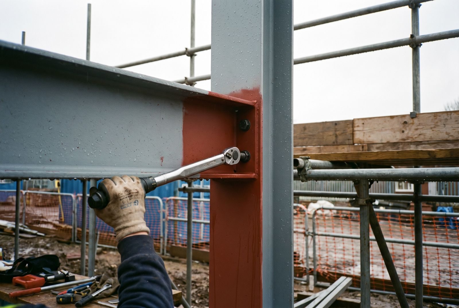
Connection design sits between the engineer's member design and the fabricator's detail. A clear allocation names who sets the forces, who designs the joint and who confirms the two agree.
Who designs the connections on a UK steel frame?
Either the engineer or the steelwork contractor, as the contract and specification allocate it. On most UK building frames the steelwork contractor designs connections to forces the engineer provides, but three allocations are common and each needs different information.
Steel connections sit on the boundary between member design and fabrication. BCSA's guidance note on design information for steelwork projects (SIGNS SN15) records that the dividing line between member design and connection design has often been found to be a grey area in steelwork contracts. The same note says the engineer is responsible for the design of the structure, and that this includes the type of connections used.
SteelConstruction.info makes the working convention explicit for simple connections: selection and verification is generally the responsibility of the steelwork contractor, who chooses the type to suit fabrication workload, economy and temporary stability during erection. If semi-continuous design is used, both the beam and its connections must be selected and verified by the frame designer. A convention is not an allocation, though. The allocation is whatever the contract documents and the specification say.
- 01
Engineer designs members and connections
The engineer sizes the members, designs every connection and shows the result on the drawings or in calculations. The fabricator detailer works to those.
- Engineer owns
- Frame analysis, member design and all connection design
- Fabricator owns
- Detailing, fabrication drawings, workmanship
- Typical use
- Exposed steelwork, semi-continuous or moment frames, complex nodes
- 02
Engineer provides forces, fabricator designs connections
The engineer designs the members and gives the design forces, tying strategy and limits on connection type. The steelwork contractor designs the connections to those inputs.
- Engineer owns
- Member design, stability, forces at each joint, limits on connection type
- Fabricator owns
- Connection design, calculations, fabrication drawings
- Typical use
- Braced frames with standard simple connections to the Green Book
- 03
Mixed allocation
Standard simple connections go to the fabricator. The engineer keeps the special joints and the interface items that cross trades.
- Engineer owns
- Moment connections, special nodes, anchorage design where holding down bolts are in tension
- Fabricator owns
- Standard simple connections, base plate design, quantifying anchor loads
- Typical use
- Most multi-storey frames with a few critical joints
The first two are the ends of a range. The third is what most frames end up as, and it is the one that most needs a written boundary, because the special joints are exactly where the fabricator has least information.
The NSSS also provides for a fourth arrangement in which the steelwork contractor designs the members as well, either starting from the member design stage or from the layout. That is a contractor's design portion for the frame itself, with a different role for the engineer, and it is covered in the guide to contractor-designed portions and performance specifications. The rest of this guide deals with the three allocations above.
What decides which allocation to use
Five factors usually decide it. The first is the structural form: braced simple construction suits standard connections, while sway frames, semi-continuous frames and long-span or cantilevered elements push connection design back to the engineer. The second is tying demand, because high tie forces can stop a connection behaving as nominally pinned. The third is appearance, where exposed steelwork needs the engineer or architect to control the detail. The fourth is the procurement route and how early the fabricator is appointed. The fifth is the capability of the fabricator who will actually win the work, which is rarely known when the specification is written. A specification that assumes a capable fabricator needs to say how capability will be checked.
How do NSSS and BCSA and SCI guidance treat connection design responsibility?
The NSSS treats connection design as an allocation made in the project specification: the Employer provides defined information, the steelwork contractor designs what the specification gives it and the engineer reviews. BCSA and SCI guidance sets out what the engineer must provide and what stays with the frame designer.
The NSSS is published by BCSA and SCI. SteelConstruction.info describes it as covering the common contractual situations where the steelwork contractor designs the connections, and in some cases the members as well, and as including checklists of the information the contractor needs to carry out that design. The current edition is the 7th, with a first revision launched in October 2023. See the guide to using the NSSS for how the document as a whole works.
In the 5th edition text reviewed for this guide, four features carry the allocation. The Employer provides the information, set out in checklists that are to be shown on the design drawings or given in the project specification. The Engineer is the designer responsible for the structural design and for reviewing and accepting the detail drawings and erection method. Design Drawings are defined as showing the forces to be developed in the connections as well as the members. The project specification takes precedence over other documents if there is a conflict. Check the wording in the relevant NSSS section of the current edition before quoting any of these.
The NSSS also defines what the engineer's review means. In the 5th edition, acceptance means the principal levels, dimensions and typical details are a correct interpretation of the design requirements and that the principles used in the connection calculations are compatible with the design. Acceptance does not relieve the steelwork contractor of responsibility for accuracy of the calculations, detail dimensions or fit-up. That wording sets the limit of what a review is for, and it comes back in the review section below.
What BCSA and SCI guidance adds
BCSA's note on simple connections (SIGNS SN51) is the most practical statement of the split. It says the steelwork contractor is normally responsible for designing standard beam-to-column and beam-to-beam connections, working from factored ultimate limit state loads, the tying strategy and the building class. It prefers design drawings to calculation sheets or descriptive clauses as the way to pass information across, asks for forces at each connection rather than a global value, and warns against instructions such as designing a moment connection for the plastic moment capacity of the section. For base plates it describes a split of responsibility between the engineer, the steelwork contractor and the main contractor.
SCI's response to a series of grey-area scenarios, published in New Steel Construction, shows where the line falls in practice.
Scroll horizontally to view all columns.
| Situation | Where responsibility falls | Source |
|---|---|---|
| Flange-to-web welds in a plate girder | Designer of the member, not the connection designer | SCI response in New Steel Construction |
| Joint resistance in a hollow section truss | Truss designer, who sets joint resistance by choosing members and geometry | SCI response, SN48 cited |
| Member too weak in combined high shear and bending | Structure designer, who selects a member of sufficient strength | SCI response |
| Tying forces so high that a connection cannot behave as nominally pinned | Original designer, who must anticipate this and design the columns for the moments | SCI response |
| Holding down bolts in tension | Fabricator quantifies anchor loads, engineer designs and specifies the anchorage and base reinforcement | SN51 and SCI response |
The pattern is consistent. Anything that sets the behaviour of the frame or the strength of a member stays with the frame designer. The fabricator designs the load path from the end of the member into its supporting element.
Two points from the SCI response matter for specifications. The Eurocodes place the effects of joint behaviour with the original designer: BS EN 1993-1-1 requires them to be taken into account where they are significant, and the UK National Annex to BS EN 1993-1-8 allows connections designed to the principles of the SCI and BCSA Green Book on simple joints (SCI P358, 2014) to be classed as nominally pinned without a stiffness calculation. The companion volume covers moment-resisting joints (SCI P398, 2013). The Green Books also contain no design rules for combined shear and axial force, so a frame whose beams carry real axial tension has left the territory of simple connections.
A caution on currency. SN15 and SN51 were written around BS 5950 and earlier NSSS editions, and SN15 refers to a BCSA and ACE joint publication on the allocation of design responsibilities that it describes as still to be published. The principles carry across to the Eurocodes. The code references do not. Check the BCSA and SCI for current guidance on the allocation of design responsibilities and for any reissue of SN15 and SN51. The guide on second-generation Eurocodes covers how the design rules for joints will change.
What must the specification and drawings state?
They must state the design forces at each connection and their basis, the tying and stability strategy, the design standard and any limits on connection type, and the specification must describe the allocation in the same terms as the drawings.
The NSSS lists the information the steelwork contractor needs. The table condenses the items that matter most for connection design, with the usual home for each. Use it as a prompt when drafting the project specification, then check it against the checklist in the edition being cited.
Scroll horizontally to view all columns.
| Item | What to state | Usually on |
|---|---|---|
| Design concept and stability | The structural form and how stability is achieved: braced bays, cores, moment frames | Project specification and general arrangement |
| Design standard | The standard and edition used for connection design, which should match the member design | Project specification |
| Forces and moments at each joint | Factored ultimate limit state values, in equilibrium at each node, given per connection and with their combinations. State the basis in a note on the drawing | Design drawings or schedule |
| High, unusual and moment connections | Identify them individually. Where loads are not given, the fabricator assumes realistic forces | Design drawings |
| Tying and robustness | The building class under Approved Document A, the tying strategy, and tie forces where they are not already in the joint forces | Project specification and drawings |
| Frame stability forces | Whether notional or equivalent horizontal forces for imperfections are already included in the joint forces, and the forces in bracing connections | Design drawings |
| Limits on connection type | Aesthetic, clearance and geometric limits, and typical details the engineer envisaged | Design drawings and specification |
| Temporary works and erection | Temporary works assumed by the engineer in the design | Project specification and general arrangement |
| Base plates and foundations | Loads at column base, foundation details and concrete grade, who designs the anchorage and any grout requirement | Design drawings and specification |
| Fabrication restrictions | Locations where holes cannot be punched, fatigue or dynamic loading, steel grades, stiffener positions, bolt assemblies | Project specification |
| Submissions | What the fabricator submits, when, and the review classification | Project specification |
Condensed from the NSSS design checklist and BCSA guidance. Illustrative layout: the content to include depends on the allocation chosen and the edition of the NSSS cited.
Forces: the single biggest source of dispute
The forces are the engineer's main deliverable under allocations two and three. Give them on drawings, in a form the fabricator can read without studying pages of output. Make sure the forces at a node are in equilibrium across the members meeting there, because a connection cannot be analysed properly from forces that do not balance. Say that the values are ultimate limit state, and say to which standard. If a generic note gives a minimum shear force where no value is shown, check that it does not exceed what the smallest beams can carry. SCI points out that such notes can silently ask for connections stronger than the member they join.
Standard connections, tying and stability forces
Specifying that simple connections follow the Green Book is efficient, provided the engineer has checked that the type is compatible with the frame analysis. Tying is the usual trap. For most simple connections the tying condition governs, and where the tie force is large the connection may stop behaving as a simple one. The engineer needs to state the Approved Document A building class (Class 1, 2A, 2B or 3 in the edition SCI cites) and the strategy, and for Class 3 the outcome of the systematic risk assessment, since the fabricator cannot reconstruct it. SteelConstruction.info explains the robustness strategies and the SCI publications that support them. Check the current edition of Approved Document A.
Forces from frame imperfections (notional forces under BS 5950, equivalent horizontal forces under the Eurocodes) are part of the frame analysis. The engineer includes them in the joint forces, and says so. Leaving the fabricator to infer them is how bracing connections end up designed for different loads from the members they connect to.
Wording the project specification
The project specification states the allocation and refers to the drawings for forces. The wording below is illustrative only and needs adapting to the NSSS edition and the contract.
Illustrative wording, not a standard clause: The Steelwork Contractor shall carry out Connection Design for all connections except those marked 'Engineer design' on the Design Drawings. Design forces and moments are ultimate limit state values and are shown at each joint on the Design Drawings. The building class and tying strategy are stated on drawing [reference]. Connections shall be compatible with the stability and analysis assumptions stated in this Specification. Where the Steelwork Contractor cannot satisfy the stated forces with a connection of the type shown or permitted, the Steelwork Contractor shall notify the Engineer before proceeding.
Drawings
Forces given per connection at each joint, ultimate limit state, in equilibrium. Moment joints identified. Tie strategy noted.
Specification
Fabricator designs connections to the drawings. Engineer design joints named. Building class and tie approach stated in the same terms.
If the drawings give forces for every joint and the specification says 'connections by others to suit', or the reverse, the fabricator is left to interpret. Check the two against each other before issue.
Three kinds of wording tend to cause trouble. Designing a moment connection for the plastic moment capacity of the member is rarely achievable economically, and SN51 advises against it. 'Connections to suit' with no forces leaves the fabricator to assume realistic values. Descriptive clauses are a poor substitute for drawings when the fabricator needs numbers. The guide to the design responsibility matrix shows how to record the allocation element by element, and the structural specification guide covers where the clause sits in the project specification.
What are the professional indemnity and contractor's design portion implications?
Giving connections to the steelwork contractor creates a contractor's design portion, which must be identified in the contract documents with its own standard of duty and insurance. It does not take the engineer out of the structural design.
Allocating connection design to the steelwork contractor creates a contractor's design portion, which needs to be identified in the contract documents and to carry a defined standard of design duty. How the duty is expressed depends on the form of contract and any amendments. Take legal advice on the standard of care wording and any fitness for purpose obligation in the form and amendments in use.
What stays with the engineer is set out in the BCSA notes. The engineer is responsible for the design of the structure, including the compatibility of the connection type with the overall performance of the frame. The steelwork contractor is accountable for the dimensional and arithmetic accuracy of its own work. SCI adds that the Eurocodes place the effects of joint behaviour with the original designer. A frame designed on the assumption of pinned joints, with large real axial forces in the beams, is the engineer's problem even if the connections are the fabricator's.
Review and professional indemnity
Three practical points affect indemnity exposure on both sides. First, say in the appointment and in the specification what review means, using the NSSS wording where it applies, so that review comments are read as comments on principle. Second, avoid review comments that tell the fabricator how to design the joint, because they blur the allocation the specification set up. Third, check what the contract requires of the steelwork contractor: professional indemnity cover for the design element, at a stated level, and evidence of competence. Take insurance advice on the level and terms of cover appropriate to connection design on the project.
CROSS-UK, the confidential structural safety reporting scheme, has a report on steelwork connection design raising concern about fabricators on small domestic projects who lack the expertise to design connections or prepare fabrication drawings. The expert panel commentary makes two points worth carrying into practice: the engineer has obligations to identify hazards arising from the design and pass the information on, and the client should employ a steelwork contractor with the skills to design and fabricate the work.
CDM and higher-risk buildings
The connection designer is a designer under CDM 2015. HSE's guidance names contractors and specialists who prepare or modify designs among those who carry designer duties. The engineer's information for connection design therefore needs to carry the hazards the engineer has identified, including any assumed erection sequence and temporary stability, which the NSSS checklist covers by asking for the temporary works the engineer assumed. The guides to the temporary works design brief and the structural designer's risk assessment go into this further.
On a higher-risk building, a Gateway 2 submission asks the applicant to show how the design complies, and an element recorded as 'by others' without a named owner is an obvious weak point. Check the Building Safety Regulator's current expectations for delegated structural design. See the guides to Gateway 2 submissions and the golden thread.
How should the engineer review and approve fabricator connection calculations?
Review the model and general arrangement first, then the connection calculations against the stated forces and frame assumptions, and record the outcome using the contract classification. Acceptance confirms compatible principles and leaves accuracy with the steelwork contractor.
Review the model and general arrangement drawings first, then the connection calculations against the stated forces and the frame assumptions, and record the outcome using the contract's classification. Acceptance confirms that the principles are compatible with the design and leaves accuracy with the steelwork contractor.
- 1
Programme
The project specification sets submission and review dates. A review that is not in the programme is a delay claim waiting to happen.
- 2
Model and general arrangement
The NSSS note recommends reviewing the computer model before any calculations. The fabricator marks each general arrangement location with a calculation or standard connection reference.
- 3
Calculations
Standard simple connections are submitted by reference. Other connections come with calculations, sketches and any complex geometry.
- 4
Review and classify
The engineer classifies each submission. In the 5th edition: A accepted, B accepted subject to comments without resubmission, C not accepted and resubmitted.
- 5
Fabrication release
Only information classified for release goes to fabrication. Changes to forces after this point reopen the cycle.
- 6
As-erected record
The fabricator provides as-erected drawings with connection calculations or references to standard connections.
Each step has an owner and a date. The record at the end is what the golden thread and the health and safety file draw on.
What the reviewer checks
- The forces used match the forces on the drawings, at the same revision and on the same basis.
- The connection type is compatible with the analysis assumptions: nominally pinned where the frame was designed as pinned, with the stiffness the frame relies on where it was not.
- Tying capacity matches the stated building class and strategy, and where tie forces have forced a stiffer connection, the effect on the supporting column has been considered.
- High, unusual and moment connections have been identified and checked individually, not only by reference to standard tables.
- Base plates, anchorages and interfaces with concrete follow the agreed split, and the engineer's anchorage design has been issued where the bolts are in tension.
- Eccentricities, stiffeners, notches and cut-outs have not weakened members the engineer sized.
- Fixings and connection details agree with the fire protection, cladding and services interfaces on the drawings.
- No member sizes have been changed without a reissue of the forces.
The review is not a recalculation. Comments should point to the principle that is incompatible with the design and leave the fabricator to resolve it. Where the engineer changes a member, the forces change, and the revised forces must be issued formally. The change control guide sets out how to keep that record, and the pre-issue technical review checklist includes a check that drawings and specification agree on who designs what.
Questions engineers ask about steel connection design responsibility
Who is responsible for steel connection design in the UK?
It depends on the contract and specification. Commonly the engineer designs the members and provides design forces, and the steelwork contractor designs the connections as a contractor's design portion. The engineer remains responsible for the design of the structure, including the compatibility of the connection type with the frame.
What forces must the engineer give the steelwork contractor?
Factored ultimate limit state forces and moments at each joint, in equilibrium at each node, with their combinations, on the drawings. Add the tying strategy and building class, forces from frame imperfections where relevant, and identify high, unusual and moment connections.
Can the engineer simply refer to the SCI Green Book?
Referring to the Green Book is efficient for standard simple connections, but the engineer must confirm that the connection type suits the frame analysis. The Green Books have no rules for combined shear and axial force, and high tie forces can stop a connection behaving as nominally pinned.
Does reviewing the fabricator's connection calculations make the engineer responsible for them?
The NSSS wording, in the edition reviewed, says acceptance confirms that principles are compatible with the design and does not relieve the steelwork contractor of responsibility for accuracy. Liability depends on the contract and appointment, so state what review means and take legal advice.
Who designs base plates and holding down bolts?
Responsibility is usually split. The engineer provides foundation details and loads, the steelwork contractor designs the base plate and quantifies anchor loads, and where bolts are in tension the engineer designs and specifies the anchorage. BCSA guidance note SN51 sets out the split.
Do second-generation Eurocodes change who designs connections?
They change the design rules and the supporting publications, not the allocation. The specification should say which generation of standards applies to member design and connection design, and the forces should be stated on the same basis.
Where Avoice fits
Allocation of connection design is a consistency problem across the specification, the drawings and the submissions record, which is the kind of problem software can check once the engineer has made the decision.
Avoice now writes structural specifications alongside architectural and building services work. Practice Rules can require that a steelwork specification states the allocation of connection design, the design standard and the form in which forces are given. The clause library can hold the practice's standard wording for the allocation and for review and acceptance, so it is not rewritten for each job. The pre-issue Technical Review compares the specification against drawings and schedules, which catches a specification that says connections are by others when the drawings give forces, or the reverse. Construction Admin tracks submittals, which suits the sequence of calculation submissions and review classifications described above, and the Compliance module keeps the CDM risk register alongside the design.
The engineering judgement stays with the engineer. Avoice can hold the structure, compare the documents and flag the mismatch. The engineer decides who designs each connection, and the contract decides what that allocation means.